EP1580412A1 - Method for sensing exhaust gas for obd - Google Patents
Method for sensing exhaust gas for obd Download PDFInfo
- Publication number
- EP1580412A1 EP1580412A1 EP05002478A EP05002478A EP1580412A1 EP 1580412 A1 EP1580412 A1 EP 1580412A1 EP 05002478 A EP05002478 A EP 05002478A EP 05002478 A EP05002478 A EP 05002478A EP 1580412 A1 EP1580412 A1 EP 1580412A1
- Authority
- EP
- European Patent Office
- Prior art keywords
- concentrations
- concentration
- sensor
- exhaust gas
- oxidation catalyst
- Prior art date
- Legal status (The legal status is an assumption and is not a legal conclusion. Google has not performed a legal analysis and makes no representation as to the accuracy of the status listed.)
- Granted
Links
Images


Classifications
-
- F—MECHANICAL ENGINEERING; LIGHTING; HEATING; WEAPONS; BLASTING
- F01—MACHINES OR ENGINES IN GENERAL; ENGINE PLANTS IN GENERAL; STEAM ENGINES
- F01N—GAS-FLOW SILENCERS OR EXHAUST APPARATUS FOR MACHINES OR ENGINES IN GENERAL; GAS-FLOW SILENCERS OR EXHAUST APPARATUS FOR INTERNAL-COMBUSTION ENGINES
- F01N3/00—Exhaust or silencing apparatus having means for purifying, rendering innocuous, or otherwise treating exhaust
- F01N3/08—Exhaust or silencing apparatus having means for purifying, rendering innocuous, or otherwise treating exhaust for rendering innocuous
- F01N3/10—Exhaust or silencing apparatus having means for purifying, rendering innocuous, or otherwise treating exhaust for rendering innocuous by thermal or catalytic conversion of noxious components of exhaust
- F01N3/18—Exhaust or silencing apparatus having means for purifying, rendering innocuous, or otherwise treating exhaust for rendering innocuous by thermal or catalytic conversion of noxious components of exhaust characterised by methods of operation; Control
- F01N3/20—Exhaust or silencing apparatus having means for purifying, rendering innocuous, or otherwise treating exhaust for rendering innocuous by thermal or catalytic conversion of noxious components of exhaust characterised by methods of operation; Control specially adapted for catalytic conversion
-
- F—MECHANICAL ENGINEERING; LIGHTING; HEATING; WEAPONS; BLASTING
- F01—MACHINES OR ENGINES IN GENERAL; ENGINE PLANTS IN GENERAL; STEAM ENGINES
- F01N—GAS-FLOW SILENCERS OR EXHAUST APPARATUS FOR MACHINES OR ENGINES IN GENERAL; GAS-FLOW SILENCERS OR EXHAUST APPARATUS FOR INTERNAL-COMBUSTION ENGINES
- F01N11/00—Monitoring or diagnostic devices for exhaust-gas treatment apparatus
-
- F—MECHANICAL ENGINEERING; LIGHTING; HEATING; WEAPONS; BLASTING
- F01—MACHINES OR ENGINES IN GENERAL; ENGINE PLANTS IN GENERAL; STEAM ENGINES
- F01N—GAS-FLOW SILENCERS OR EXHAUST APPARATUS FOR MACHINES OR ENGINES IN GENERAL; GAS-FLOW SILENCERS OR EXHAUST APPARATUS FOR INTERNAL-COMBUSTION ENGINES
- F01N11/00—Monitoring or diagnostic devices for exhaust-gas treatment apparatus
- F01N11/007—Monitoring or diagnostic devices for exhaust-gas treatment apparatus the diagnostic devices measuring oxygen or air concentration downstream of the exhaust apparatus
-
- F—MECHANICAL ENGINEERING; LIGHTING; HEATING; WEAPONS; BLASTING
- F01—MACHINES OR ENGINES IN GENERAL; ENGINE PLANTS IN GENERAL; STEAM ENGINES
- F01N—GAS-FLOW SILENCERS OR EXHAUST APPARATUS FOR MACHINES OR ENGINES IN GENERAL; GAS-FLOW SILENCERS OR EXHAUST APPARATUS FOR INTERNAL-COMBUSTION ENGINES
- F01N2560/00—Exhaust systems with means for detecting or measuring exhaust gas components or characteristics
- F01N2560/02—Exhaust systems with means for detecting or measuring exhaust gas components or characteristics the means being an exhaust gas sensor
- F01N2560/026—Exhaust systems with means for detecting or measuring exhaust gas components or characteristics the means being an exhaust gas sensor for measuring or detecting NOx
-
- F—MECHANICAL ENGINEERING; LIGHTING; HEATING; WEAPONS; BLASTING
- F01—MACHINES OR ENGINES IN GENERAL; ENGINE PLANTS IN GENERAL; STEAM ENGINES
- F01N—GAS-FLOW SILENCERS OR EXHAUST APPARATUS FOR MACHINES OR ENGINES IN GENERAL; GAS-FLOW SILENCERS OR EXHAUST APPARATUS FOR INTERNAL-COMBUSTION ENGINES
- F01N2560/00—Exhaust systems with means for detecting or measuring exhaust gas components or characteristics
- F01N2560/06—Exhaust systems with means for detecting or measuring exhaust gas components or characteristics the means being a temperature sensor
-
- Y—GENERAL TAGGING OF NEW TECHNOLOGICAL DEVELOPMENTS; GENERAL TAGGING OF CROSS-SECTIONAL TECHNOLOGIES SPANNING OVER SEVERAL SECTIONS OF THE IPC; TECHNICAL SUBJECTS COVERED BY FORMER USPC CROSS-REFERENCE ART COLLECTIONS [XRACs] AND DIGESTS
- Y02—TECHNOLOGIES OR APPLICATIONS FOR MITIGATION OR ADAPTATION AGAINST CLIMATE CHANGE
- Y02A—TECHNOLOGIES FOR ADAPTATION TO CLIMATE CHANGE
- Y02A50/00—TECHNOLOGIES FOR ADAPTATION TO CLIMATE CHANGE in human health protection, e.g. against extreme weather
- Y02A50/20—Air quality improvement or preservation, e.g. vehicle emission control or emission reduction by using catalytic converters
-
- Y—GENERAL TAGGING OF NEW TECHNOLOGICAL DEVELOPMENTS; GENERAL TAGGING OF CROSS-SECTIONAL TECHNOLOGIES SPANNING OVER SEVERAL SECTIONS OF THE IPC; TECHNICAL SUBJECTS COVERED BY FORMER USPC CROSS-REFERENCE ART COLLECTIONS [XRACs] AND DIGESTS
- Y02—TECHNOLOGIES OR APPLICATIONS FOR MITIGATION OR ADAPTATION AGAINST CLIMATE CHANGE
- Y02T—CLIMATE CHANGE MITIGATION TECHNOLOGIES RELATED TO TRANSPORTATION
- Y02T10/00—Road transport of goods or passengers
- Y02T10/10—Internal combustion engine [ICE] based vehicles
- Y02T10/40—Engine management systems
Definitions
- the present invention relates to a method for sensing exhaust gas for OBD.
- OBD on-board diagnostic system
- the invention was made in view of the above and has its object to make it possible to detect or determine all of NO x , PM, HC and CO concentrations necessary for realization of OBD by virtue of an existing NO, sensor which can be mounted in a vehicle.
- the invention is directed to a method for sensing exhaust gas for OBD which comprises detecting a NO x concentration in the exhaust gas by a NO x sensor arranged in an exhaust pipe, PM, HC and CO concentrations being determined in conversion, on the basis of an O 2 concentration sensed in the course of detection of said NO x concentration, from mutual correspondences of the concentrations.
- the existing NO x sensor which has to utilize an O 2 concentration in the course of detection of the NO x concentration in an exhaust gas, inherently accommodates an extensive O 2 sensor which detects an O 2 concentration in the exhaust gas.
- the PM, HC and CO concentrations which have correspondences with the O 2 concentration are determined in conversion so that all of the PM, HC and CO concentrations are obtained in alternative measurement in addition to the NO x concentration directly sensed by the NO x sensor.
- the fact that the PM, HC and CO concentrations have correspondences with the O 2 concentration is the inventor's knowledge.
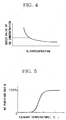
- the PM, HC and CO concentrations greatly depend on combustibility in an engine and tend to remarkably increase when the combustibility becomes insufficient due to lowering of the O 2 concentration.
- a temperature sensor may be arranged on an inlet side of said oxidation catalyst to detect an exhaust temperature, purified ratios of the PM, HC and CO concentrations being determined depending upon catalytic activity of said oxidation catalyst at a current exhaust temperature, the PM, HC and CO concentrations being compensated on the basis of the purified ratios.
- the oxidation catalyst when the oxidation catalyst is arranged in the exhaust pipe and downstream of the NO x sensor, the NO x and O 2 concentrations once detected by the NO x sensor are lowered downstream since the exhaust gas passes through the oxidation catalyst and is purified; therefore, compensation must be done for the decrements to determine final values of the PM, HC and CO concentrations.
- the purified ratios of the PM, HC and CO concentrations depend on catalytic activity of the oxidation catalyst which in turn depends on an exhaust temperature on the inlet side of the oxidation catalyst.
- the purified ratios of the PM, HC and CO concentrations are determined depending upon the catalytic activity of the oxidation catalyst at a current exhaust temperature and the PM, HC and CO concentrations are compensated on the basis of the purified ratios determined, so that the final values of the PM, HC and CO concentrations in the exhaust gas purified through the oxidation catalysts can be determined.
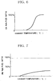
- Figs. 1 to 7 show an embodiment of a method for sensing exhaust gas for OBD according to the invention in which exhaust gas 3 is discharged via an exhaust manifold 2 from a diesel engine 1 and flows through an exhaust pipe 4.
- a casing 6 Arranged in the exhaust pipe 4 is a casing 6 which accommodates an oxidation catalyst 5 in the form of a flow-through type honeycomb structure.
- a NO x sensor 8 Arranged on a most upstream side in the exhaust pipe 4 is a NO x sensor 8 which is positioned adjacent to a turbine outlet of a turbocharger 7. Arranged on an inlet side of the casing 6 is a temperature sensor 9 which detects temperature of the exhaust gas 3. Detection signals 8a and 9a from the sensors 8 and 9, respectively, are inputted to an electronic control unit (ECU) 10 which is an engine controlling computer.
- ECU electronice control unit
- ECU 10 When NO x , PM, HC and CO concentrations grasped on the basis of detection signals 8a and 9a from the sensors 8 and 9, respectively, have something abnormal, then ECU 10 outputs a lightening command signal 11 a to light a caution-advisory indicator 11 on an instrument panel.
- the existing NO x sensor 8 has to utilize an O 2 concentration in the course of detection of the NO x concentration, therefore the sensor 8 inherently accommodates an extensive O 2 sensor which senses the O 2 concentration in the exhaust gas 3.
- the PM, HC and CO concentrations which have correspondences with the O 2 concentration are determined in conversion by the ECU 10, so that all of the PM, HC and CO concentrations are obtained in alternative measurement in addition to the NO x concentration directly sensed by the NO x sensor 8.
- an oxidation catalyst 5 is arranged in the exhaust pipe 4 and downstream of the NO x sensor 8, after the NO x and O 2 concentrations are sensed by the NO x sensor 8, the PM, HC and CO concentrations are lowered since the exhaust gas 3 passes through the oxidation catalyst 5 and is purified; therefore, the compensation must be done for the decrements to determined the last values of the PM, HC and CO concentrations.
- these purified ratios of the PM, HC and CO concentrations are determined depending on the catalytic activity which in turn depends upon the exhaust temperature on the inlet side of the oxidation catalyst 5; therefore, the purified ratios of the PM, HC and CO concentrations are determined depending upon the catalytic activity of the oxidation catalyst 5 at the current exhaust temperature.
- the determined PM, HC and CO concentrations as to the exhaust gas 3 adjacent to the turbine outlet of said turbocharger 7 are compensated to obtain final values of PM, HC and CO concentrations in the exhaust gas 3 which has passed through the oxidation catalyst 5 and is purified.
- the flow-through type oxidation catalyst 5 is singly arranged with no combination with another catalyst.
- the oxidation catalyst 5 is carried by a particulate filter or is followed by a separate particulate filter, then as shown in two-dot-chain lines in the graph of Fig. 7, almost all of PM are captured in the particulate filter with no connection with the purified ratios by the oxidation catalyst 5, so that it can be regarded with no specific determination that the final PM concentration has been lowered to a substantially constant concentration.
- Fig. 1 Shown in Fig. 1 is the single caution-advisory indicator 11; however, the caution-advisory indicator 11 may be arranged for each of the NO x , PM, HC and CO concentrations.
- the caution-advisory indicator 11 may be arranged for each of the NO x , PM, HC and CO concentrations.
- Upon detection of abnormality preferably, such occurrence of abnormality is recorded in a memory in the ECU 10 and/or a suitable correction operation is made to the diesel engine 1.
- a method for sensing exhaust gas for OBD in a method for sensing exhaust gas for OBD according to the invention, all of NO x , PM, HC and CO concentrations can be determined by utilization of an existing NO x sensor 8 which is mountable in a vehicle. Even if the oxidation catalyst 5 is arranged in the exhaust pipe 4, the PM, HC and CO concentrations can be suitably compensated on the basis of an exhaust temperature detected by the temperature sensor 9 on the inlet side of the oxidation catalyst 5; as a result, the OBD can be realized readily and at a lower cost. It is to be understood that a method for sensing exhaust gas for OBD according to the invention is not limited to the above embodiment and that various changes and modifications may be effected within the gist of the invention. For example, it may be applicable to a vehicle with an exhaust pipe 4 having no oxidation catalyst 5.
Landscapes
- Engineering & Computer Science (AREA)
- Chemical & Material Sciences (AREA)
- Chemical Kinetics & Catalysis (AREA)
- Combustion & Propulsion (AREA)
- Mechanical Engineering (AREA)
- General Engineering & Computer Science (AREA)
- Health & Medical Sciences (AREA)
- Toxicology (AREA)
- Exhaust Gas After Treatment (AREA)
- Combined Controls Of Internal Combustion Engines (AREA)
Abstract
Description
It is to be understood that a method for sensing exhaust gas for OBD according to the invention is not limited to the above embodiment and that various changes and modifications may be effected within the gist of the invention. For example, it may be applicable to a vehicle with an exhaust pipe 4 having no
Claims (2)
- A method for sensing exhaust gas for OBD which comprises detecting a NOx concentration in the exhaust gas by a NOx sensor arranged in an exhaust pipe, PM, HC and CO concentrations being determined in conversion, on the basis of an O2 concentration sensed in the course of detection of said NOx concentration, from mutual correspondences of the concentrations.
- The method according to claim 1 wherein an oxidation catalyst is arranged in the exhaust pipe and downstream of the NOx sensor, a temperature sensor being arranged on an inlet side of said oxidation catalyst to detect an exhaust temperature, purified ratios of the PM, HC and CO concentrations being determined depending upon catalytic activity of the oxidation catalyst at a current exhaust temperature, the PM, HC and CO concentrations being compensated on the basis of the purified ratios.
Applications Claiming Priority (2)
| Application Number | Priority Date | Filing Date | Title |
|---|---|---|---|
| JP2004091725 | 2004-03-26 | ||
| JP2004091725A JP2005273613A (en) | 2004-03-26 | 2004-03-26 | Exhaust gas sensing method for OBD |
Publications (2)
| Publication Number | Publication Date |
|---|---|
| EP1580412A1 true EP1580412A1 (en) | 2005-09-28 |
| EP1580412B1 EP1580412B1 (en) | 2008-04-16 |
Family
ID=34858492
Family Applications (1)
| Application Number | Title | Priority Date | Filing Date |
|---|---|---|---|
| EP05002478A Expired - Lifetime EP1580412B1 (en) | 2004-03-26 | 2005-02-07 | Method for sensing exhaust gas for on-board diagnosis |
Country Status (4)
| Country | Link |
|---|---|
| US (1) | US20050210868A1 (en) |
| EP (1) | EP1580412B1 (en) |
| JP (1) | JP2005273613A (en) |
| DE (1) | DE602005006038T2 (en) |
Cited By (1)
| Publication number | Priority date | Publication date | Assignee | Title |
|---|---|---|---|---|
| GB2479122A (en) * | 2010-03-29 | 2011-10-05 | Gm Global Tech Operations Inc | Determining soot rate in an exhaust by measuring its oxygen concentration |
Families Citing this family (23)
| Publication number | Priority date | Publication date | Assignee | Title |
|---|---|---|---|---|
| US7467614B2 (en) | 2004-12-29 | 2008-12-23 | Honeywell International Inc. | Pedal position and/or pedal change rate for use in control of an engine |
| US7389773B2 (en) * | 2005-08-18 | 2008-06-24 | Honeywell International Inc. | Emissions sensors for fuel control in engines |
| US8060290B2 (en) | 2008-07-17 | 2011-11-15 | Honeywell International Inc. | Configurable automotive controller |
| US8620461B2 (en) | 2009-09-24 | 2013-12-31 | Honeywell International, Inc. | Method and system for updating tuning parameters of a controller |
| US8504175B2 (en) | 2010-06-02 | 2013-08-06 | Honeywell International Inc. | Using model predictive control to optimize variable trajectories and system control |
| US8689541B2 (en) * | 2011-02-16 | 2014-04-08 | GM Global Technology Operations LLC | Valvetrain control method and apparatus for conserving combustion heat |
| US8788182B2 (en) | 2011-09-07 | 2014-07-22 | GM Global Technology Operations LLC | Engine speed based valvetrain control systems and methods |
| US8707679B2 (en) | 2011-09-07 | 2014-04-29 | GM Global Technology Operations LLC | Catalyst temperature based valvetrain control systems and methods |
| US9677493B2 (en) | 2011-09-19 | 2017-06-13 | Honeywell Spol, S.R.O. | Coordinated engine and emissions control system |
| US20130111905A1 (en) | 2011-11-04 | 2013-05-09 | Honeywell Spol. S.R.O. | Integrated optimization and control of an engine and aftertreatment system |
| US9650934B2 (en) | 2011-11-04 | 2017-05-16 | Honeywell spol.s.r.o. | Engine and aftertreatment optimization system |
| US9038369B2 (en) | 2013-02-13 | 2015-05-26 | Cummins Inc. | Systems and methods for aftertreatment system diagnostics |
| EP3051367B1 (en) | 2015-01-28 | 2020-11-25 | Honeywell spol s.r.o. | An approach and system for handling constraints for measured disturbances with uncertain preview |
| EP3056706A1 (en) | 2015-02-16 | 2016-08-17 | Honeywell International Inc. | An approach for aftertreatment system modeling and model identification |
| EP3091212A1 (en) | 2015-05-06 | 2016-11-09 | Honeywell International Inc. | An identification approach for internal combustion engine mean value models |
| EP3125052B1 (en) | 2015-07-31 | 2020-09-02 | Garrett Transportation I Inc. | Quadratic program solver for mpc using variable ordering |
| US10272779B2 (en) | 2015-08-05 | 2019-04-30 | Garrett Transportation I Inc. | System and approach for dynamic vehicle speed optimization |
| US10415492B2 (en) | 2016-01-29 | 2019-09-17 | Garrett Transportation I Inc. | Engine system with inferential sensor |
| US10124750B2 (en) | 2016-04-26 | 2018-11-13 | Honeywell International Inc. | Vehicle security module system |
| US10036338B2 (en) | 2016-04-26 | 2018-07-31 | Honeywell International Inc. | Condition-based powertrain control system |
| EP3548729B1 (en) | 2016-11-29 | 2023-02-22 | Garrett Transportation I Inc. | An inferential flow sensor |
| US11057213B2 (en) | 2017-10-13 | 2021-07-06 | Garrett Transportation I, Inc. | Authentication system for electronic control unit on a bus |
| US12247504B1 (en) | 2023-09-20 | 2025-03-11 | GM Global Technology Operations LLC | Systems and methods for catalyst health diagnosing and fuel system control improvement |
Citations (2)
| Publication number | Priority date | Publication date | Assignee | Title |
|---|---|---|---|---|
| WO2001006223A1 (en) * | 1999-07-16 | 2001-01-25 | Volkswagen Aktiengesellschaft | Method for detecting the state of a catalytic converter system |
| US6588251B2 (en) * | 1998-06-29 | 2003-07-08 | Siemens Aktiengesellschaft | Method for checking the dynamic behavior of a measuring sensor in the exhaust tract of an internal combustion engine |
Family Cites Families (7)
| Publication number | Priority date | Publication date | Assignee | Title |
|---|---|---|---|---|
| JP3802168B2 (en) * | 1996-12-10 | 2006-07-26 | 日本碍子株式会社 | Gas sensor and deterioration diagnosis method of exhaust gas purification apparatus using the same |
| US5746049A (en) * | 1996-12-13 | 1998-05-05 | Ford Global Technologies, Inc. | Method and apparatus for estimating and controlling no x trap temperature |
| EP1077375B1 (en) * | 1997-03-21 | 2012-06-20 | Ngk Spark Plug Co., Ltd | Method and apparatus for measuring NOx gas concentration |
| TR200001900T2 (en) * | 1998-01-05 | 2001-01-22 | The United States Environmental Protection Agency | Real time vehicle exhaust gas modular flow meter and information system while driving. |
| JP3684934B2 (en) * | 1999-08-30 | 2005-08-17 | 三菱自動車工業株式会社 | Exhaust gas purification device for internal combustion engine |
| US6311484B1 (en) * | 2000-02-22 | 2001-11-06 | Engelhard Corporation | System for reducing NOx transient emission |
| DE10124235B4 (en) * | 2001-05-18 | 2004-08-12 | Esytec Energie- Und Systemtechnik Gmbh | Method and device for the comprehensive characterization and control of the exhaust gas and the control of engines, especially internal combustion engines, and of components of the exhaust gas aftertreatment |
-
2004
- 2004-03-26 JP JP2004091725A patent/JP2005273613A/en active Pending
-
2005
- 2005-02-03 US US11/048,790 patent/US20050210868A1/en not_active Abandoned
- 2005-02-07 EP EP05002478A patent/EP1580412B1/en not_active Expired - Lifetime
- 2005-02-07 DE DE602005006038T patent/DE602005006038T2/en not_active Expired - Lifetime
Patent Citations (2)
| Publication number | Priority date | Publication date | Assignee | Title |
|---|---|---|---|---|
| US6588251B2 (en) * | 1998-06-29 | 2003-07-08 | Siemens Aktiengesellschaft | Method for checking the dynamic behavior of a measuring sensor in the exhaust tract of an internal combustion engine |
| WO2001006223A1 (en) * | 1999-07-16 | 2001-01-25 | Volkswagen Aktiengesellschaft | Method for detecting the state of a catalytic converter system |
Cited By (1)
| Publication number | Priority date | Publication date | Assignee | Title |
|---|---|---|---|---|
| GB2479122A (en) * | 2010-03-29 | 2011-10-05 | Gm Global Tech Operations Inc | Determining soot rate in an exhaust by measuring its oxygen concentration |
Also Published As
| Publication number | Publication date |
|---|---|
| DE602005006038T2 (en) | 2009-05-14 |
| JP2005273613A (en) | 2005-10-06 |
| DE602005006038D1 (en) | 2008-05-29 |
| EP1580412B1 (en) | 2008-04-16 |
| US20050210868A1 (en) | 2005-09-29 |
Similar Documents
| Publication | Publication Date | Title |
|---|---|---|
| EP1580412B1 (en) | Method for sensing exhaust gas for on-board diagnosis | |
| US8826730B2 (en) | Method of diagnosing regeneration failure of exhaust emission control device | |
| EP2261489B1 (en) | Method for controlling exhaust gas purification system and exhaust gas purification system | |
| US6952953B2 (en) | Method and device for monitoring a sensor | |
| US8186146B2 (en) | After-treatment component detection system | |
| US20120023911A1 (en) | Detection of exhaust particulate filter substrate failure | |
| KR101234638B1 (en) | METHOD FOR PREDICTING NOx AMOUNT AMD EXHAUST SYSTEM USING THE SAME | |
| US20050188686A1 (en) | Exhaust gas purification system of internal combustion engine | |
| JP4930636B2 (en) | Exhaust gas purification system for internal combustion engine | |
| US7752901B1 (en) | Method of diagnosing the presence of an exhaust after-treatment component and a use of the method for vehicle on-board diagnosis | |
| US7478553B2 (en) | Method for detecting excessive burn | |
| CN108035789B (en) | Gasoline vehicle multi-stage three-way catalyst performance online monitoring system and method | |
| US8538661B2 (en) | Exhaust treatment methods and systems | |
| US7624571B2 (en) | Exhaust gas purifying apparatus for internal combustion engine and method for estimating collected amount of exhaust particles | |
| JP7855990B2 (en) | Vehicle anomaly detection system | |
| JP4162017B2 (en) | Exhaust purification device for internal combustion engine and exhaust purification method for internal combustion engine | |
| JP2009257209A (en) | Exhaust emission control system for internal combustion engine | |
| CN107542558B (en) | Catalyst diagnostic system and method | |
| JP2010159643A (en) | Method for detecting abnormality of temperature sensor | |
| CN114198186B (en) | Method and device for diagnosing a coated gasoline particulate filter of an exhaust system of an internal combustion engine | |
| US20240093625A1 (en) | Method for operating a particle filter taking the ash quantity into consideration | |
| JPH03121240A (en) | Exhaust emission purifying catalyst failure diagnosing method | |
| JP4894569B2 (en) | Temperature sensor failure diagnosis device | |
| US12203398B2 (en) | Method and device for determining the sulphur content in an exhaust gas channel of a motor vehicle in relation to the supplied fuel | |
| JP2009127495A (en) | Filter failure detection device for internal combustion engine |
Legal Events
| Date | Code | Title | Description |
|---|---|---|---|
| PUAI | Public reference made under article 153(3) epc to a published international application that has entered the european phase |
Free format text: ORIGINAL CODE: 0009012 |
|
| AK | Designated contracting states |
Kind code of ref document: A1 Designated state(s): AT BE BG CH CY CZ DE DK EE ES FI FR GB GR HU IE IS IT LI LT LU MC NL PL PT RO SE SI SK TR |
|
| AX | Request for extension of the european patent |
Extension state: AL BA HR LV MK YU |
|
| 17P | Request for examination filed |
Effective date: 20060114 |
|
| AKX | Designation fees paid |
Designated state(s): DE FR GB |
|
| 17Q | First examination report despatched |
Effective date: 20060301 |
|
| GRAP | Despatch of communication of intention to grant a patent |
Free format text: ORIGINAL CODE: EPIDOSNIGR1 |
|
| RTI1 | Title (correction) |
Free format text: METHOD FOR SENSING EXHAUST GAS FOR ON-BOARD DIAGNOSIS |
|
| GRAS | Grant fee paid |
Free format text: ORIGINAL CODE: EPIDOSNIGR3 |
|
| GRAA | (expected) grant |
Free format text: ORIGINAL CODE: 0009210 |
|
| AK | Designated contracting states |
Kind code of ref document: B1 Designated state(s): DE FR GB |
|
| REF | Corresponds to: |
Ref document number: 602005006038 Country of ref document: DE Date of ref document: 20080529 Kind code of ref document: P |
|
| ET | Fr: translation filed | ||
| PLBE | No opposition filed within time limit |
Free format text: ORIGINAL CODE: 0009261 |
|
| STAA | Information on the status of an ep patent application or granted ep patent |
Free format text: STATUS: NO OPPOSITION FILED WITHIN TIME LIMIT |
|
| 26N | No opposition filed |
Effective date: 20090119 |
|
| GBPC | Gb: european patent ceased through non-payment of renewal fee |
Effective date: 20090207 |
|
| REG | Reference to a national code |
Ref country code: FR Ref legal event code: ST Effective date: 20091030 |
|
| PG25 | Lapsed in a contracting state [announced via postgrant information from national office to epo] |
Ref country code: GB Free format text: LAPSE BECAUSE OF NON-PAYMENT OF DUE FEES Effective date: 20090207 Ref country code: FR Free format text: LAPSE BECAUSE OF NON-PAYMENT OF DUE FEES Effective date: 20090302 |
|
| PGFP | Annual fee paid to national office [announced via postgrant information from national office to epo] |
Ref country code: DE Payment date: 20150224 Year of fee payment: 11 |
|
| REG | Reference to a national code |
Ref country code: DE Ref legal event code: R119 Ref document number: 602005006038 Country of ref document: DE |
|
| PG25 | Lapsed in a contracting state [announced via postgrant information from national office to epo] |
Ref country code: DE Free format text: LAPSE BECAUSE OF NON-PAYMENT OF DUE FEES Effective date: 20160901 |