EP1580303A2 - Hydrodynamic means for electrochemical cells - Google Patents
Hydrodynamic means for electrochemical cells Download PDFInfo
- Publication number
- EP1580303A2 EP1580303A2 EP05006598A EP05006598A EP1580303A2 EP 1580303 A2 EP1580303 A2 EP 1580303A2 EP 05006598 A EP05006598 A EP 05006598A EP 05006598 A EP05006598 A EP 05006598A EP 1580303 A2 EP1580303 A2 EP 1580303A2
- Authority
- EP
- European Patent Office
- Prior art keywords
- hydrodynamic means
- electrolyte
- strips
- hydrodynamic
- ribs
- Prior art date
- Legal status (The legal status is an assumption and is not a legal conclusion. Google has not performed a legal analysis and makes no representation as to the accuracy of the status listed.)
- Withdrawn
Links
Images






Classifications
-
- C—CHEMISTRY; METALLURGY
- C25—ELECTROLYTIC OR ELECTROPHORETIC PROCESSES; APPARATUS THEREFOR
- C25B—ELECTROLYTIC OR ELECTROPHORETIC PROCESSES FOR THE PRODUCTION OF COMPOUNDS OR NON-METALS; APPARATUS THEREFOR
- C25B9/00—Cells or assemblies of cells; Constructional parts of cells; Assemblies of constructional parts, e.g. electrode-diaphragm assemblies; Process-related cell features
- C25B9/60—Constructional parts of cells
- C25B9/65—Means for supplying current; Electrode connections; Electric inter-cell connections
-
- C—CHEMISTRY; METALLURGY
- C25—ELECTROLYTIC OR ELECTROPHORETIC PROCESSES; APPARATUS THEREFOR
- C25B—ELECTROLYTIC OR ELECTROPHORETIC PROCESSES FOR THE PRODUCTION OF COMPOUNDS OR NON-METALS; APPARATUS THEREFOR
- C25B9/00—Cells or assemblies of cells; Constructional parts of cells; Assemblies of constructional parts, e.g. electrode-diaphragm assemblies; Process-related cell features
- C25B9/17—Cells comprising dimensionally-stable non-movable electrodes; Assemblies of constructional parts thereof
- C25B9/19—Cells comprising dimensionally-stable non-movable electrodes; Assemblies of constructional parts thereof with diaphragms
Definitions
- the present invention is directed to hydrodynamic means suitable for installation in existing electrochemical cells wherein the electrodes are connected to the backwalls by means of elongated supports, such as ribs or the like, and gaseous products are generated.
- Typical processes characterized by the formation of gaseous products are the well known chlor-alkali electrolysis, hydrochloric acid solution electrolysis and water electrolysis, only to mention those which are particularly important from an industrial point of view.
- the internal recirculation of the electrolytes plays an extremely important role in preventing the formation of dead areas wherein bubbles may be entrapped and the concentration of the electrolyte may change, both factors leading to an increase of cell voltage with the associated worsening of the consumption of electric energy.
- the patent literature discloses a number of electrolytic cells equipped with internal hydrodynamic means such as baffles or channels primarily directed to separate the ascending flow of the mixed phase comprising the generated gas and the liquid electrolyte from the downcoming flow of liquid electrolyte which has been degassed in the top section of the cell: the difference of density between mixed and degassed phases is the driving force which induces the internal recirculation known as natural or gas lift recirculation. It is immediately evident that the recirculation attains the maximal value when the mentioned difference of density is also maximal, as it happens when the downcoming electrolyte flow is substantially free of gas.
- Patent literature discloses a number of devices directed to facilitate the coalescence of bubbles: the common point for all disclosures is represented by a restriction of the cross section available for the ascending mixed phase flow localized in the very top section of the cell.
- Patent Application DE-A 198 50 071 is here assumed as one of the most representative documents wherein the mentioned hydrodynamic means and the device for the coalescence of the tiny bubbles are disclosed: in particular, the hydrodynamic means are obtained by folding a metal sheet in a zig-zag or wave-like shape followed by fixing the wave, such as by welding, to the backwall of each compartment of the cell. The electrodes represented by foraminous sheets are then connected, again by welding, to the apexes of the zig-zag structure whereby the zig-zag structure also functions as current distributor from the backwall to the electrodes.
- the space limited by the backwall and the internal surface of the zig-zag structure is only available for the downcoming flow of degassed electrolyte, whereas the mixed gas ⁇ electrolyte phase is totally confined in the space defined by the process-side surface of the zig-zag structure and the electrode.
- the upper edge of the wave-like section is provided with a protruding baffle which is directed to restrict the cross section for the passage of the mixed phase, thus facilitating the coalescence of the smaller size bubbles.
- hydrodynamic means consisting of flat strips or folded strips having a L or Z or C or trapezoidal shape, said flat strips or folded strips being characterized by a certain degree of elasticity which facilitates the insertion between each couple of rows of studs or ribs or any other type of elongated profiles by simply pressing them with the optional cooperation of the new electrode sheets.
- hydrodynamic means such as the types mentioned above, which are manufactured by using metals or plastic materials provided with chemical inertia, elasticity and low tendency to creep relaxation under the electrolysis conditions.
- Figure 1 shows the top view cross section of an existing cell 1 where the electrodes 2 are supported by rows of studs or ribs 3 or other similar elongated profiles fixed, e. g. by welding, on the backwall 4.
- the ribs are generally provided with perforations (not shown in the figure) to allow for a certain transversal mixing of the electrolytes such as to avoid the formation of areas with different concentration.
- the catalytic activity of the electrodes is tied to the presence of a thin coating film containing certain elements such as the platinum group metals: during the electrolysis the mechanical stresses caused by the detachment of gas bubbles and/or chemical attack, when anomalous conditions appear in the cell, induce a slow consumption of the film until its residual traces left on the surface of the electrodes are unable to support the electrolysis process.
- the cell is disassembled and the half shells are subjected to reactivation, which generally comprises the detachment of the worn-out electrodes 2 followed by fixing, for example by welding, of new electrodes.
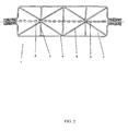
- the space defined by the electrodes 2, the ribs 3 and the backwall 4 is divided in two regions 6 and 7, respectively dedicated to the ascending flow 8 of gas-electrolyte mixed phase and to the down coming flow of electrolyte 9 separated from the gas bubbles in the upper section 10 of the cell.
- the strips have a width slightly greater than the diagonal of each space between two contiguous rows of ribs and are kept in position thanks to their elasticity and the pressing action of the new electrodes which are fastened by a suitable jig before being welded to the top of the ribs.
- the strips may be manufactured with plastic materials, in addition to the currently used metals, provided that the selected plastic materials be chemically resistant to the electrolysis environment and to the creep relaxation at the temperature of operation.
- plastic materials such as polyvinylidenfluoride, perfluorinated alcoxyethylene copolymers, polychlorotrifluoroethylene are particularly suitable.
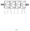
- the hydrodynamic means may also be shaped in the form of curved strips 11 as shown in figure 4: the insertion procedure and the mechanical behaviour remain the same discussed in the case of the preceding figure 2. However, the unobstructed perforations of the ribs only allow the transversal mixing of the degassed electrolyte.
- the plain strips of figure 2 may be folded to obtain an L -shaped section 12 as shown in figure 5: these strips are advantageously inserted between the rows of ribs to form a saw tooth pattern characterized in that the shorter length of the L obstructs the perforations of the ribs so that no transversal mixing is allowed: in this case a more effective motion of both the mixed phase and the degassed electrolyte is generated: however it is required the distribution of the electrolyte in the lower section of the cell be highly uniform.
- the hydrodynamic means are given the Z shape 13 sketched in figure 6 by suitably folding the strips.
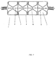
- a further design suitable for the hydrodynamic means of the invention is represented by the use of trapezoidal or C - shaped folded strips 14 (figure 7, only the trapezoidal strips shown), which are characterized by a behaviour quite similar to that discussed before in the case of the strips of figure 5 and figure 6.
- the trapezoidal and C-shaped means represent a two-fold advantageous design solution.
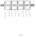
- the trapezoidal and C-shaped strips may be easily equipped on the upper edge with protruding baffles 16 (figure 9: top view of the cross section, figure 10: side view of a cross section), which are aimed to restrict the passage of the gas-electrolyte mixed phase in the very top section of the cell: the increase of the linear velocity of the mixed phase enhances the coalescence of the gas bubbles, in particular the tiny bubbles, greatly facilitating the degassing of the electrolyte and, as a consequence, the internal recirculation.
- the baffles may be integral with the body of the strip thus avoiding time consuming and expensive procedures of welding or gluing by means of proper stamping of suitably cut flat strips.
- the regions dedicated to the ascending gas-electrolyte mixed phase and to the downcoming degassed electrolyte do not have necessarily the -same cross section as is the case for the means of figures 2,5 and 6, but on the contrary their ratio may be adjusted so that the linear velocity in the two regions is optimized for the best degassing and recirculation.
- hydrodynamic means and the procedure of insertion and fixing described for the case of the retrofitting of existing cells during the reactivation of the catalytic activity can also be employed for the construction of new cells.
Landscapes
- Chemical & Material Sciences (AREA)
- Engineering & Computer Science (AREA)
- Chemical Kinetics & Catalysis (AREA)
- Electrochemistry (AREA)
- Materials Engineering (AREA)
- Metallurgy (AREA)
- Organic Chemistry (AREA)
- Electrolytic Production Of Non-Metals, Compounds, Apparatuses Therefor (AREA)
- Hybrid Cells (AREA)
Abstract
Description
- figure 1
- shows the top view of a cross section of an existing cell comprising two half shells, each one provided with vertical ribs supporting the electrode sheets and provided with apertures (not shown) to allow transversal mixing of the electrolytes;
- figure 2
- represents the top view of a cross section of the same cell of figure 1, with the strip-shaped hydrodynamic means of the invention inserted in a zig-zag configuration between the rows of vertical ribs;
- figure 3
- is the side view of a cross section of the same cell of figure 2 with the arrows indicating the separated ascending and downcoming flows of the internal recirculation generated by the hydrodynamic means;
- figure 4
- shows another embodiment of the cell of figure 2 where the hydrodynamic means have a curved cross section;
- figure 5
- schematizes a cross section similar to that of figure 2, with L-shaped folded strips inserted between the rows of ribs to form a saw tooth pattern wherein the apertures of all ribs of each are obstructed;
- figure 6
- represents another embodiment of the invention similar to that of figure 2 with the Z-shaped folded strips inserted between the rows of ribs, again forming a saw tooth pattern where the apertures of all ribs are obstructed;
- figure 7
- represents a further embodiment of the invention similar to that of figure 2 with trapezoidal folded strips inserted between the rows of ribs;
- figure 8
- shows the top view of a cross section of a preferred embodiment of the trapezoidal folded strips of figure 7 provided with side lips directed to facilitate the retention between the rows of ribs during the construction;
- figure 9
- shows a cross section similar to that of figure 7 where the trapezoidal folded strips are further provided on the upper edge with a protruding baffle directed to reduce the cross section of the passage available for the gas-electrolyte mixed phase for the improved coalescence of the dispersed bubbles;
- figure 10
- schematizes a side view of a cross section of the embodiment of figure 9.
Claims (18)
- Hydrodynamic means directed to establish or improve in gas evolving electrochemical cells the internal recirculation of both the gas-electrolyte mixed phase and the degassed electrolyte, comprising two half shells, at least one of said half shells including a backwall, rows of studs or ribs or other types of elongated profiles supporting the electrodes characterized in that the hydrodynamic means are inserted between each contiguous couple of rows and have the form of flat strips or folded strips with a L- or Z-or C- shaped or trapezoidal cross section.
- The hydrodynamic means of claim 1 characterized by dividing the space defined by the backwall, the electrodes and the rows in two separate regions directed to the ascending flow of gas-electrolyte mixed phase and to the downcoming flow of degassed electrolyte.
- The hydrodynamic means of claim 1 or 2 characterized in that the ribs or other elongated profiles are provided with perforations for the transversal mixing of the electrolyte.
- The hydrodynamic means of claim 3 characterized in that said perforations are at least in part obstructed by said folded strips.
- The hydrodynamic means of anyone of the preceding claims characterized by being kept in place under the effect of the pressing action of the electrodes.
- The hydrodynamic means of anyone of claims 1 to 4 characterized by being kept in position under the effect of their structural elasticity.
- The hydrodynamic means of anyone of claims 1 to 4 characterized by being kept in position under the effect of the elastic restraint of side lips.
- The hydrodynamic means of claim 2 characterized in that said regions have substantially equivalent cross section of passage for said mixed phase and said degassed electrolyte.
- The hydrodynamic means of claim 2 characterized in that said regions formed by said C-shaped or trapezoidal folded strips have an adjustable ratio of cross section of passage for said mixed phase and said degassed electrolyte
- The hydrodynamic means of claim 1 characterized in that said C-shaped or trapezoidal folded strips are provided with protruding baffles on their upper edge.
- The hydrodynamic means of claim 10 characterized in that said baffles are integral parts of said C-shaped or trapezoidal folded strips.
- The hydrodynamic means of anyone of the preceding claims 1 characterized in that said plain strips or folded strips are manufactured with metals or plastic materials.
- The hydrodynamic means of claim 12 characterized in that said plastic materials are fluorinated polymers.
- The hydrodynamic means of claim 13 characterized in that said fluorinated polymers are selected from the group of polyvinylidenfluoride, perfluorinated alcoxyethylene copolymers, polychlorotrifluoroethylene.
- Method of installation of the hydrodynamic means of anyone of claims 1-14 characterized in that said flat strips or folded strips are inserted between each contiguous couple of rows during the reactivation of the electrochemical cells.
- An electrochemical cell comprising the hydrodynamic means of anyone of claims 1-14.
- The electrochemical cell of claim 16 characterized in that it is a cell suitable for chlor-alkali electrolysis.
- The cell of claim 16 characterized in that it is a cell suitable for the electrolysis of hydrochloric acid solutions.
Applications Claiming Priority (2)
| Application Number | Priority Date | Filing Date | Title |
|---|---|---|---|
| DE102004014696A DE102004014696A1 (en) | 2004-03-25 | 2004-03-25 | Hydrodynamic devices for electrochemical cells |
| DE102004014696 | 2004-03-25 |
Publications (2)
| Publication Number | Publication Date |
|---|---|
| EP1580303A2 true EP1580303A2 (en) | 2005-09-28 |
| EP1580303A3 EP1580303A3 (en) | 2008-06-25 |
Family
ID=34854055
Family Applications (1)
| Application Number | Title | Priority Date | Filing Date |
|---|---|---|---|
| EP05006598A Withdrawn EP1580303A3 (en) | 2004-03-25 | 2005-03-24 | Hydrodynamic means for electrochemical cells |
Country Status (2)
| Country | Link |
|---|---|
| EP (1) | EP1580303A3 (en) |
| DE (1) | DE102004014696A1 (en) |
Cited By (5)
| Publication number | Priority date | Publication date | Assignee | Title |
|---|---|---|---|---|
| ITMI20082035A1 (en) * | 2008-11-17 | 2010-05-18 | Uhdenora Spa | ELEMENTARY CELL AND RELATIVE MODULAR ELECTROLISER FOR ELECTROLYTIC PROCESSES |
| IT201700004794A1 (en) * | 2017-01-18 | 2018-07-18 | Andrea Capriccioli | ELECTROLYZER FOR H2 PRODUCTION |
| TWI686511B (en) * | 2017-09-29 | 2020-03-01 | 德商帝森克魯伯伍德氯工程公司 | Electrolysis device |
| US11390956B1 (en) | 2021-06-01 | 2022-07-19 | Verdagy, Inc. | Anode and/or cathode pan assemblies in an electrochemical cell, and methods to use and manufacture thereof |
| WO2023060146A3 (en) * | 2021-10-05 | 2023-05-19 | Verdagy, Inc. | Systems and methods for producing hydrogen gas |
Family Cites Families (7)
| Publication number | Priority date | Publication date | Assignee | Title |
|---|---|---|---|---|
| IT1165047B (en) * | 1979-05-03 | 1987-04-22 | Oronzio De Nora Impianti | PROCEDURE FOR IMPROVING THE TRANSPORT OF MATERIAL TO AN ELECTRODE AND RELATED HYDRODYNAMIC MEDIA |
| IT1163737B (en) * | 1979-11-29 | 1987-04-08 | Oronzio De Nora Impianti | BIPOLAR ELECTROLIZER INCLUDING MEANS TO GENERATE THE INTERNAL RECIRCULATION OF THE ELECTROLYTE AND ELECTROLYSIS PROCEDURE |
| JPS58123885A (en) * | 1982-01-20 | 1983-07-23 | Kanto Denka Kogyo Kk | Cathode constructing body for salt electrolytic cell of ion exchange membrane method |
| US5454925A (en) * | 1994-05-03 | 1995-10-03 | Eltech Systems Corporation | Repair of mesh electrode spaced from electrode pan |
| DE19850071A1 (en) * | 1998-10-30 | 2000-05-04 | Bayer Ag | Membrane electrolysis cell with active gas / liquid separation |
| IT1319259B1 (en) * | 2000-10-31 | 2003-09-26 | Nora Impianti S P A Ora De Nor | ELECTROLYTIC CELL WITH RENEWABLE ELECTRODIC STRUCTURES AND METHOD FOR THE REPLACEMENT OF THE SAME. |
| ITMI20022382A1 (en) * | 2002-11-11 | 2004-05-12 | De Nora Elettrodi Spa | ELECTRODES FOR ELECTROMETALLURGY |
-
2004
- 2004-03-25 DE DE102004014696A patent/DE102004014696A1/en not_active Withdrawn
-
2005
- 2005-03-24 EP EP05006598A patent/EP1580303A3/en not_active Withdrawn
Cited By (16)
| Publication number | Priority date | Publication date | Assignee | Title |
|---|---|---|---|---|
| WO2010055152A1 (en) * | 2008-11-17 | 2010-05-20 | Uhdenora S.P.A. | Elementary cell and relevant modular electrolyser for electrolytic processes |
| KR20110095348A (en) * | 2008-11-17 | 2011-08-24 | 유데노라 에스.피.에이. | Elemental cell and associated modular electrolysis device for electrolysis process |
| EA019177B1 (en) * | 2008-11-17 | 2014-01-30 | Уденора С.П.А. | ELECTRONIC ELECTROLYSIS CELL AND ELECTROLYSER BASED ON IT |
| US9062383B2 (en) | 2008-11-17 | 2015-06-23 | Uhdenora S.P.A. | Elementary cell and relevant modular electrolyser for electrolytic processes |
| ITMI20082035A1 (en) * | 2008-11-17 | 2010-05-18 | Uhdenora Spa | ELEMENTARY CELL AND RELATIVE MODULAR ELECTROLISER FOR ELECTROLYTIC PROCESSES |
| IT201700004794A1 (en) * | 2017-01-18 | 2018-07-18 | Andrea Capriccioli | ELECTROLYZER FOR H2 PRODUCTION |
| WO2018134766A1 (en) * | 2017-01-18 | 2018-07-26 | Andrea Capriccioli | Electrolytic cell for the production of h2 |
| US11608561B2 (en) | 2017-09-29 | 2023-03-21 | Thyssenkrupp Uhde Chlorine Engineers Gmbh | Electrolysis device |
| TWI686511B (en) * | 2017-09-29 | 2020-03-01 | 德商帝森克魯伯伍德氯工程公司 | Electrolysis device |
| US11390956B1 (en) | 2021-06-01 | 2022-07-19 | Verdagy, Inc. | Anode and/or cathode pan assemblies in an electrochemical cell, and methods to use and manufacture thereof |
| WO2022256043A1 (en) * | 2021-06-01 | 2022-12-08 | Verdagy, Inc. | Anode and/or cathode pan assemblies in an electrochemical cell, and methods to use and manufacture thereof |
| US12209319B2 (en) | 2021-06-01 | 2025-01-28 | Verdagy, Inc. | Anode and/or cathode pan assemblies in an electrochemical cell, and methods to use and manufacture thereof |
| AU2021449337B2 (en) * | 2021-06-01 | 2025-04-24 | Verdagy, Inc. | Anode and/or cathode pan assemblies in an electrochemical cell, and methods to use and manufacture thereof |
| WO2023060146A3 (en) * | 2021-10-05 | 2023-05-19 | Verdagy, Inc. | Systems and methods for producing hydrogen gas |
| US12037694B2 (en) | 2021-10-05 | 2024-07-16 | Verdagy, Inc. | Systems and methods for producing hydrogen gas |
| US12173417B2 (en) | 2021-10-05 | 2024-12-24 | Verdagy, Inc. | Systems and methods for producing hydrogen gas |
Also Published As
| Publication number | Publication date |
|---|---|
| EP1580303A3 (en) | 2008-06-25 |
| DE102004014696A1 (en) | 2005-10-13 |
Similar Documents
| Publication | Publication Date | Title |
|---|---|---|
| SU1126210A3 (en) | Bipolar electrode for electrochemical processes | |
| EP0991794B1 (en) | Ion exchange membrane bipolar electrolyzer | |
| US3849281A (en) | Bipolar hypochlorite cell | |
| IL45747A (en) | Electrolytic cells for the electrolysis of alkali metal chloride solutions | |
| US20160312370A1 (en) | Electrochemical cell without an electrolyte-impermeable barrier | |
| US11884559B2 (en) | Electrochemical cell for wastewater treatment with improved electrical protection | |
| JPH0657874B2 (en) | Membrane type electrolytic cell | |
| US5660698A (en) | Electrode configuration for gas-forming electrolytic processes in membrane cells or diapragm cells | |
| AU639186B2 (en) | Electrode comprising channel-forming threads | |
| US20040069621A1 (en) | Electrochemicall cell | |
| ITMI20060054A1 (en) | ELASTIC CURRENT DISTRIBUTOR FOR PERCOLATOR CELLS | |
| US4448663A (en) | Double L-shaped electrode for brine electrolysis cell | |
| EP0469062B1 (en) | Electrode structure for an electrolytic cell | |
| JPS5943885A (en) | Electrode device for gas generation electrolytic cell and vertical plate electrode therefor | |
| US5087344A (en) | Electrolysis cell for gas-evolving electrolytic processes | |
| GB2051131A (en) | Mass transfer in electrolysis cells | |
| FI61208C (en) | DIAFRAGMACELL AVSEDD FOER ELEKTROLYS AV EN VATTENLOESNING AV EN ALKALIMETALLKLORIDID | |
| EP0864004A1 (en) | Filter press electrolyzer electrode assembly | |
| CN1272470C (en) | Electrolytic cells with renewable electrode structures and method for substituting the same | |
| US4690748A (en) | Plastic electrochemical cell terminal unit | |
| CA2103216A1 (en) | Cell | |
| US4118306A (en) | Anode constructions for electrolysis cells | |
| CN212127635U (en) | A Novel Electrode Device Considering Simplicity and Efficiency | |
| US8425754B2 (en) | Cathode for electrolysis cell | |
| EP1641962A1 (en) | Expandable anode for diaphragm cells |
Legal Events
| Date | Code | Title | Description |
|---|---|---|---|
| PUAI | Public reference made under article 153(3) epc to a published international application that has entered the european phase |
Free format text: ORIGINAL CODE: 0009012 |
|
| AK | Designated contracting states |
Kind code of ref document: A2 Designated state(s): AT BE BG CH CY CZ DE DK EE ES FI FR GB GR HU IE IS IT LI LT LU MC NL PL PT RO SE SI SK TR |
|
| AX | Request for extension of the european patent |
Extension state: AL BA HR LV MK YU |
|
| RIN1 | Information on inventor provided before grant (corrected) |
Inventor name: FABIAN, PETER |
|
| PUAL | Search report despatched |
Free format text: ORIGINAL CODE: 0009013 |
|
| AK | Designated contracting states |
Kind code of ref document: A3 Designated state(s): AT BE BG CH CY CZ DE DK EE ES FI FR GB GR HU IE IS IT LI LT LU MC NL PL PT RO SE SI SK TR |
|
| AX | Request for extension of the european patent |
Extension state: AL BA HR LV MK YU |
|
| AKX | Designation fees paid | ||
| STAA | Information on the status of an ep patent application or granted ep patent |
Free format text: STATUS: THE APPLICATION IS DEEMED TO BE WITHDRAWN |
|
| 18D | Application deemed to be withdrawn |
Effective date: 20081001 |
|
| REG | Reference to a national code |
Ref country code: DE Ref legal event code: 8566 |