EP1580054A2 - Roller blind with integrated winding compensation - Google Patents
Roller blind with integrated winding compensation Download PDFInfo
- Publication number
- EP1580054A2 EP1580054A2 EP05004609A EP05004609A EP1580054A2 EP 1580054 A2 EP1580054 A2 EP 1580054A2 EP 05004609 A EP05004609 A EP 05004609A EP 05004609 A EP05004609 A EP 05004609A EP 1580054 A2 EP1580054 A2 EP 1580054A2
- Authority
- EP
- European Patent Office
- Prior art keywords
- roller blind
- winding shaft
- edge
- window roller
- blind according
- Prior art date
- Legal status (The legal status is an assumption and is not a legal conclusion. Google has not performed a legal analysis and makes no representation as to the accuracy of the status listed.)
- Withdrawn
Links
Images

Classifications
-
- B—PERFORMING OPERATIONS; TRANSPORTING
- B60—VEHICLES IN GENERAL
- B60J—WINDOWS, WINDSCREENS, NON-FIXED ROOFS, DOORS, OR SIMILAR DEVICES FOR VEHICLES; REMOVABLE EXTERNAL PROTECTIVE COVERINGS SPECIALLY ADAPTED FOR VEHICLES
- B60J1/00—Windows; Windscreens; Accessories therefor
- B60J1/20—Accessories, e.g. wind deflectors, blinds
- B60J1/2011—Blinds; curtains or screens reducing heat or light intensity
- B60J1/2013—Roller blinds
- B60J1/2036—Roller blinds characterised by structural elements
- B60J1/2041—Blind sheets, e.g. shape of sheets, reinforcements in sheets, materials therefor
-
- B—PERFORMING OPERATIONS; TRANSPORTING
- B60—VEHICLES IN GENERAL
- B60B—VEHICLE WHEELS; CASTORS; AXLES FOR WHEELS OR CASTORS; INCREASING WHEEL ADHESION
- B60B1/00—Spoked wheels; Spokes thereof
-
- B—PERFORMING OPERATIONS; TRANSPORTING
- B60—VEHICLES IN GENERAL
- B60J—WINDOWS, WINDSCREENS, NON-FIXED ROOFS, DOORS, OR SIMILAR DEVICES FOR VEHICLES; REMOVABLE EXTERNAL PROTECTIVE COVERINGS SPECIALLY ADAPTED FOR VEHICLES
- B60J1/00—Windows; Windscreens; Accessories therefor
- B60J1/20—Accessories, e.g. wind deflectors, blinds
- B60J1/2011—Blinds; curtains or screens reducing heat or light intensity
- B60J1/2013—Roller blinds
- B60J1/2066—Arrangement of blinds in vehicles
- B60J1/2086—Arrangement of blinds in vehicles specially adapted for openable windows, e.g. side window
Definitions
- Passenger cars usually feature in the rear body area via further side windows.
- These side windows can be mounted either directly in the body or they are part of rear side doors. As far as windows in side doors are concerned, these are divided again, in an approximate trapezoidal Part and a triangular part.
- the trapezoidal Part stems from the fact that the side window in this area is lowered to the window to be able to open.
- the top edge of the side window is set usually made up of a substantially straight section and a curved section together to one To avoid jumping into the trick-shaped area. Indeed can the upper edge of the quadrangular part in the first Approximation to be considered straight. Due to the body shape however, the course of this section is not parallel to the lower edge. With the side window lowered this has the consequence that the top edge of the disc is still visible in the front end of the window slot, while she dives clearly down in the back.
- roller blind shaft below the lower edge of the window it is arranged to be at the top of the window runs parallel.
- Such an arrangement is generally available however, the space inside a door opposite.
- the designer is forced to roll the blind to accommodate parallel to the lower edge.
- This arrangement conditionally in the area towards the front end of the vehicle a longer vertical extension of the roller blind than in the area to the rear. When winding up, that's why more material rolled up in the area of the front edge of the roller blind be considered in the area of the trailing edge.
- the new window blind is as in the state of Technique the roller blind with the additional piece for generating the conical hub in one piece.
- the roller blind sits from a developable from the winding shaft section and a permanent remaining on the winding shaft Section together.
- the permanent on the winding shaft remaining section is separated by a dividing line, a Base edge and two side edges limited. This results an approximate trapezoidal shape, where the base edge, which is shorter than the dividing line, in a very sharp Angle to the dividing line runs.
- One of the two side edges extends approximately at right angles to the dividing line, while the other side edge is at an acute angle runs, which is greater than the acute angle between the dividing line and the base edge.
- a reinforcing strip is provided, the starting from the base edge and parallel to the first side edge runs. Because of this shape, the in itself cylindrical winding shaft along the base edge reproducible be connected with the roller blind exactly. It results an edge on which the winding shaft are aligned can. In addition, the winding shaft is in this way over a relatively long piece already from the beginning with the winding shaft connected, so that tilting during winding of the compensating piece are excluded.
- the unwound from the winding shaft section of Roller blind is made from one end edge and two side edges and the already mentioned dividing line.
- the end edge runs at an acute angle to the dividing line, causing the roller blind is longer in the area of the first side edge as in the area of the second side edge.
- the required diameter ratio at the winding shaft that is necessary so that at the end of the winding process the end edge of the roller blind parallel to the winding shaft or at a desired angle to the angle shaft runs, is achieved when the reinforcing strip a Having a length equal to the height of a triangle, whose base is the base edge and whose one side is from the extension of the first side edge and the other Side is the extension of the second side edge.
- the mentioned height is perpendicular to the base edge, what in Generally with the extension of the first side edge is equal, i. this imaginary triangle represents a right-angled or approximately right-angled triangle in which one catheter has the base edge and the other Kathete is the extension of the first side edge.
- the depth of the recess is between 1 and 15 mm, preferably at about 8 mm.
- the return whose width is the width of the reinforcing strip corresponds, cut a little way.
- the width of the incision is between 1 to 10 mm, preferably around the 3 mm and also has about this depth.
- the Width of the reinforcing strip is in the range between 10 mm and 60 mm, this width being determined by the length of the Winding shaft directs.
- the section remaining permanently on the winding shaft is preferably with stripes or sections with glued to the winding shaft. This saves adhesive and the risk of trapped air later in use in case of temperature fluctuations can cause problems avoided.
- strip-shaped adhesive areas extend expediently on the one hand parallel to the dividing line and on the other hand parallel to the base edge or in the return area parallel to its edge, in the same direction shows as the base edge, as they put out of this one Section forms.
- the reinforcing strip is also adhesive Strip equipped, so by all means the compensation section over the entire length of the base edge cohesively connected to the winding shaft.
- the width of the respective strip-shaped area is smaller than the circumference of the winding shaft.
- the reinforcing strip can be integral with the shade be cut. He can also as a separate Strip be executed. In any case, is expediently the reinforcing strip in the area of the base edge materially connected to the main part of the compensation piece. The other end, which is towards the dividing line shows, remains free against it, so that it wound up can align freely and no wrinkles occur due to compression.
- the second side edge can be about as straight edge of go through the dividing line to the base edge.
- the second side edge perform.
- the length of this extension corresponds to the width of the adhesive strip. From there out follows the second side edge of the edge of the adhesive Stripe, at about a quarter to a third of the Width of the roller blind over a concave curved line in the otherwise straight base edge to pass. hereby assembly is easier because it is not necessary roll up blind material over the entire length.
- the roller blind is advantageously made of a in Essentially non-stretchable knitted fabrics.
- a knitted fabric is limp and can be used in a small amount without wrinkling the area are sheared. It is under shear one Offset of the end edge of the roller blind opposite the dividing line in the direction parallel to the dividing line.
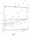
- Figure 1 illustrates the broken cut off rear area a car.
- the figure illustrates a Look at the right inside, which is not illustrated left inside is mirror image.
- the Presentation is simplified, insofar as, for example, internal structures the body like stiffeners, fasteners not shown because their representation for understanding the invention is not required.
- the illustrated body section 1 includes Roof 2, from the side of a B-pillar 3 to a not illustrated floor group leads. A corresponding B-pillar would be on the left-hand side of the vehicle to think.
- the roof 2 goes to its trailing edge a tailgate 4 over, in the usual way at the Lower edge of the roof 2 is hinged.
- a rear window 5 is housed in the tailgate 4, in the tailgate 4, in the tailgate 4, a rear window 5 is housed.
- a moving window 12 which in the usual way, for example. Electric is to move up and down to open the window 11.
- foot areas 15 and 16 of the floor group are located between the two rear side doors 7 .
- the gap between the upper edge of the rear seat back 14th and the inner contour of the tailgate 4 is replaced by a hat rack 17 closed when opening the tailgate 4 in known manner is pivoted upward.
- a Trunk available Below the parcel shelf 17 and behind the rear seat back 14 is a Trunk available.
- the located in the side door 7 window 11 is of a lower straight edge 18 and a substantially straight upper edge 19 and two side edges 20 and 21 limited.
- the upper edge 19 extends below, as shown an acute angle to the lower edge 18, i. the distance between the upper edge and the lower edge 18 is greater in the area of the front side edge 21 than in Area of the rear side edge 20.
- Between these edges 18, 19, 20, 21 of the window 11 may be a roller blind 22, as shown to be stretched.
- the roller blind 22 runs through a slot in the lower window reveal.
- the roller blind 22 belongs to a side window roller blind 23, whose for the Understanding the invention essential parts shown in Figure 2 are.
- the side window roller 23 is a manually operated window blind.
- the roller blind 22 is a section of a roller blind blank 24.
- the roller blind blank 24 is made the section 22, which can be clamped in front of the window 11 Part, and a section 25 together, whose exact structure is described below.
- In the retracted Condition are the roller blind blanks 22 and 24 on wound up the winding shaft 26.
- the winding shaft 26 contains in her Inside a spring motor 27.
- the spring motor 27 is one end at 28 connected to the tubular winding shaft 26, while the other end of the spring motor on a pin 29th is fixed, the rotation in the interior of the door 7 below the lower edge of the window 18 is received.
- the winding shaft 26 has a cylindrical Pin 31, which is rotatably mounted in a bearing block, the at the appropriate distance also below the bottom Window edge 18 is located.
- the winding shaft 26 is how mentions a cylindrical steel tube and it runs in mounted state within the door 7, i. between the Exterior skin of door and door inner panel parallel to the lower edge 18 of the window 11th
- the roller blind section 22 is from a first side edge 32, an approximately parallel second Side edge 33, a top or end edge 34 and a Dividing line 35 limited.
- the top or end edge 34 is with an excerpt profile 36 stiffening this edge, which has approximately in the middle of a hook 37, either with the upper edge of the window 12 of the window 11 to is hooked or in a special eyelet on the inside the side door 7 is to hang.
- the pull-out profile 36 is straight and thus approximates in its course the upper edge 19 of the side window eleventh
- the trapezoidal shape of the window 11 is also section 22, i. the extendable part of the Roller blind 22 trapezoidal, in the sense that the dividing line 35, at which section 22 passes into section 25, at an acute angle to the top or end edge 34 or in the extension profile 36 runs.
- the integrally in the section 22 passing section 25 serves the purpose of ensuring that if the Section 22 is wound on the winding shaft 26, the Extensions profile 36 exactly parallel to the lower edge 18 of the Window 11 runs so as to close the slot, through the roller blind 22 during extension from the Door interior is pulled out.
- This gap can be the same Be cleft, by the well in a known manner, the retractable Side window disappears when opening the window.
- the section 25 thus ultimately serves as a winding compensation to make sure that in the area of the side edge 32 more material is wound on the winding shaft 26 than in the area of the side edge 33.
- the winding compensation forming portion 25 of the Blank 24 is from a first side edge 38, a its opposite second side edge 39, the Dividing line 35 and a base edge 41 limited.
- the base edge 41 runs at an acute angle to the dividing line 35, as shown so that both the base edge 41 and also the top edge 34 in the same direction on the dividing line 35 to converge.
- the side edge 38 is a straight edge without Jump into the side edge 32 passes.
- the side edge 32 may have a slight kink at 42 to open this way to approach a section of a ring.
- the base edge 41 is significantly shorter as it corresponds to the length of the dividing line 35.
- the length the base edge 41 is about half to one third the length of the dividing line 35.
- the base edge 41 starts at a corner 42, which is located in the inner area between the Extensions of the two side edges 32 and 33 is located and leads straight from there to an incision 43.
- the base edge 41 forms a straight Return 44, whose terminal edge parallel to the extension the longer piece of the base edge 41 runs.
- the base edge 41 jumps approx. 8 mm back.
- the width of the incision 43 is between 2 mm and 10 mm preferably about 4 mm while the depth of the Incision is about 4 mm long.
- the second side edge 39 begins at the corner 42 and begins with a concave section 45, which at 46 in a straight piece, which is approximately parallel to the dividing line 35, but at a short distance to a corner 47 runs. From here, the side edge 39 goes with a Straight section 48 directly into the side edge 33rd above.
- the reinforcing strip 49 is about 40 mm wide, measured in the direction parallel to the base edge 41.
- section 25 approaches of the blank 24 about a triangle.
- This triangle is about a right triangle, of which one is a catheter the dividing line 35 is at which the two sections 22 and 25 in one piece into each other.
- the other catheter is the extension of the first side edge 38, while the Hypotenuse is a dashed line 51, on the one hand begins in the area where the dividing line 35 the second Side edge 33 cuts and the other by the Corner 42 goes, at the base edge 41 in the second side edge 39 passes.
- the dashed extension 52 of Side edge 38 and hypotenuse 51 intersect at one Tip 53.
- the distance of this tip 53 from the edge of the recess 44 corresponds to the length of the rectangular Reinforcement strip 49, measured from the edge 44 up to its the dividing line 35 adjacent edge 54th
- the blank 24 thus obtained is in the region of the compensating section 25 with the outer surface of the winding shaft 26 materially connected. This runs along the base edge 41 between the recess 43 and the corner 42 the page facing the viewer a klebdress equipped Strip 55. Its width is low on the distance of the base edge 41 from the parting line 35.
- a another adhesive strip 56 is located on the viewer facing side of the reinforcing strip 49 between the recess 43 and the side edge 38. The width of the strip 56 corresponds to the width of the Stsammlungs 55.
- Another on the viewer's side existing adhesive strip 57 follows Dividing line 35 and it extends from parting line 35 in the section 25.
- the width of the strip 56 corresponds the length of the straight portion 48 of the side edge 39.
- the winding shaft 46 is on the adhesive Strip 55 launched, in such a way that its longitudinal axis lies parallel to the base edge 41. It will be as possible glued close to the base edge 41, so they initially not sticking to the strip during gluing 56 attached or touched, because in this area the material is doubly, what the clean bonding of the Streaks past strip 55 following notch 43 would.
- the winding shaft 26 on the viewer's side on the section 25 rolled in the direction of the parting line 35. there it moves along a ring, its center right of the side edges 33 and 48 lies. During the Rolling it runs on the reinforcing strip 49, while they are on the flat plane at the other end Rolling pad. At the end of the rolling motion is the Winding shaft with its axis parallel to the parting line 35th and the strip 57 fixes the roll permanently on the Winding shaft 26.
- a winding shaft achieved, which is no longer cylindrical as the winding shaft 26, but an approximate slender cone that where the side edge is 48, the diameter of the original Winding shaft 26 has, while in the field of Side edge 38 corresponding to the number of turns of the winding shaft through the material of the blank 24 in diameter is enlarged.
- the difference in diameter of the generated cone-shaped Aufwickelköpers, consisting of the winding shaft 26 and the Section 25, is chosen so that at the end of the winding process the top or end edge 34 with the pull-out profile 36 at a predetermined desired angle the axis of the winding shaft 26 extends. In the described If the edge should lie parallel to the lower edge of the window 18, around the existing extract slot or gap largely close.
- the invention essentially relates to the type and Way like a slender conical bobbin for a Roller blind can be produced. This was the embodiment explained using a manual roller blind. It understands However, without further ado that also an electric Operation is possible.
- the upper edge runs the roller blind in the extended state under a pointed Angle to the axis of the winding shaft.
- To wind up the winding shaft has a conical shape to have.
- the conical shape is achieved by the Roller blind continues in a trapezoidal section, the permanently on the cylindrical winding shaft remains. This Section is placed next to one edge by one Reinforced reinforcing strip in thickness.
Abstract
Description
PKW verfügen in der Regel in dem hinteren Karosseriebereich über weitere Seitenfenster. Diese Seitenfenster können entweder unmittelbar in der Karosserie angebracht sein oder sie sind Bestandteil von hinteren Seitentüren. Soweit es sich um Fenster in Seitentüren handelt, sind diese nochmals unterteilt, und zwar in einen angenäherten trapezförmigen Teil und einen dreieckförmigen Teil. Der trapezförmige Teil ergibt sich aus dem Umstand, dass die Seitenscheibe in diesem Bereich absenkbar ist, um das Fenster öffnen zu können. Die obere Kante des Seitenfensters setzt sich in aller Regel aus einem im Wesentlichen geraden Abschnitt und einem gekrümmten Abschnitt zusammen, um einen Sprung in den dreickförmigen Bereich zu vermeiden. Allerdings kann die Oberkante des viereckigen Teils in erster Näherung als gerade angesehen werden. Zufolge der Karosserieform ist jedoch der Verlauf dieses Abschnittes nicht parallel zu der Unterkante. Bei heruntergelassener Seitenscheibe hat dies zur Folge, dass die Oberkante der Scheibe im vorderen Ende des Fensterschlitzes noch sichtbar ist, während sie im hinteren Teil deutlich nach unten wegtaucht.Passenger cars usually feature in the rear body area via further side windows. These side windows can be mounted either directly in the body or they are part of rear side doors. As far as windows in side doors are concerned, these are divided again, in an approximate trapezoidal Part and a triangular part. The trapezoidal Part stems from the fact that the side window in this area is lowered to the window to be able to open. The top edge of the side window is set usually made up of a substantially straight section and a curved section together to one To avoid jumping into the trick-shaped area. Indeed can the upper edge of the quadrangular part in the first Approximation to be considered straight. Due to the body shape however, the course of this section is not parallel to the lower edge. With the side window lowered this has the consequence that the top edge of the disc is still visible in the front end of the window slot, while she dives clearly down in the back.
Dieser Umstand ist bei Fensterscheiben hinnehmbar. Wenn das Seitenfenster jedoch durch ein Rollo abgeschattet werden soll, entsteht hier ein Problem, denn es ist unerwünscht, dass die Oberkante des Seitenfensterrollos entweder über die Unterkante des Fensters übersteht oder einen großen Spalt frei lässt, in den Gegenstände hineinfallen können. Dies ist deswegen von wesentlicher Bedeutung, weil im hinteren Bereich von PKWs häufig auch Kinder sitzen und die Gefahr groß ist, dass durch die Spalte irgendwelche Teile ins Innere der Tür fallen.This circumstance is acceptable for windows. However, if the side window is shaded by a roller blind a problem arises because it is undesirable that the top of the side window roller blind either protrudes beyond the lower edge of the window or one large gap left, fall into the objects can. This is essential because Children often sit in the back area of cars as well the danger is great that through the column any Parts fall inside the door.
Es besteht deswegen ein erhöhter Bedarf dafür, bei Seitenfensterrollos im hinteren Bereich dafür zu sorgen, dass die Oberkante der Rollobahn den Auszugsschlitz vollständig schließt.There is therefore an increased need for, at Side window blinds in the rear area to ensure that the upper edge of the roller blind the pull-out slot completely closes.
Diese Bedingung könnte theoretisch erfüllt werden, indem die Rollowelle unterhalb der unteren Fensterkante so angeordnet wird, dass sie zu der Oberkante des Fensters parallel verläuft. Einer solchen Anordnung stehen im Allgemeinen jedoch die Platzverhältnisse im Inneren einer Tür entgegen. Der Konstrukteur ist gezwungen die Rollowelle parallel zur Unterkante unterzubringen. Diese Anordnung bedingt im zum Vorderende des Fahrzeugs hin gelegene Bereich eine längere vertikale Ausdehnung der Rollobahn als im zum Heck gelegene Bereich. Beim Aufwickeln muss deswegen im Bereich der Vorderkante der Rollobahn mehr Material aufgewickelt werden als im Bereich der Hinterkante.This condition could theoretically be fulfilled by the roller blind shaft below the lower edge of the window it is arranged to be at the top of the window runs parallel. Such an arrangement is generally available however, the space inside a door opposite. The designer is forced to roll the blind to accommodate parallel to the lower edge. This arrangement conditionally in the area towards the front end of the vehicle a longer vertical extension of the roller blind than in the area to the rear. When winding up, that's why more material rolled up in the area of the front edge of the roller blind be considered in the area of the trailing edge.
Es ist hierzu aus der EP 0 111 270 bekannt eine konische Wickelwelle zu simulieren. Die Wickelwelle ist ansich strikt zylindrisch, wobei die gewünschte Konizität erreicht wird, indem die Rollobahn, die an der Wickelwelle befestigt ist, einen dreieckförmigen Fortsatz aufweist. Der dreieckförmige Fortsatz ist einstückig mit dem von der Wickelwelle abwickelbaren Abschnitt. Dieser Fortsatz wird begrenzt von einer Trennlinie, die zu der Wickelwelle parallel ist und den Fortsatz von den abwickelbaren Teil abgrenzt. Weiterhin wird der Fortsatz von zwei Seitenkanten begrenzt, die jeweils von der Trennlinie ausgehen, so dass gedanklich ein rechtwinkliges Dreieck entsteht, dessen eine Kathete die Trennlinie ist.It is known from EP 0 111 270 a conical To simulate winding shaft. The winding shaft is ansich strictly cylindrical, with the desired conicity is achieved by the roller blind, attached to the winding shaft is attached, has a triangular-shaped extension. Of the triangular extension is integral with that of the winding shaft developable section. This extension will bounded by a dividing line parallel to the winding shaft is and delimits the extension from the unwindable part. Furthermore, the extension of two side edges limited, each starting from the dividing line, so that mentally creates a right-angled triangle, whose one Kathete is the dividing line.
Diese Anordnung ist jedoch auf solche Anwendungen begrenzt, bei denen die Länge der kurzen Seitenkante, die in Verlängerung der vorderen Seitenkante der Rollobahn verläuft und somit die andere Kathete des Dreiecks bildet, eine Länge hat, die kleiner ist als der Umfang der Wickelwelle. Andernfalls würde sich beim Aufwickeln während der Herstellung die Spitze in unkontrollierbarer Weise umschlagen.However, this arrangement is limited to such applications, where the length of the short side edge, the in Extension of the front side edge of the roller blind runs and thus forms the other cathetus of the triangle, has a length that is smaller than the circumference of the winding shaft. Otherwise, when winding up during the Make the tip in an uncontrollable manner.
Im Übrigen ist dieser Rollobahnzuschnitt während der Montage nicht einfach zu handhaben, da der Reproduzierbarkeit Grenzen gesetzt sind.Incidentally, this roller blind blank during the Assembly not easy to handle, because of the reproducibility Limits are set.
Es ist zu bedenken, dass die Wickelwelle beim Aufwickeln des dreieckigen Ausgleichsabschnitts sich letztendlich längs eines Kreisbogens bewegt, wobei der Radius des Kreisbogens durch die Lage des Ausgleichsabschnittes und der Spitze dieses Ausgleichsabschnittes festgelegt ist. Die mangelnde Steifigkeit des Materials für die Rollobahn verkompliziert die Verhältnisse zusätzlich.It should be noted that the winding shaft when winding up of the triangular balancing section ultimately moved along a circular arc, the radius of the Circular arc by the position of the compensation section and the peak of this compensation section is fixed. The lack of rigidity of the material for the roller blind complicates the conditions in addition.
Eine weitere Lösung ist aus der FR 2 750 158 bekannt. Hier wird die konische Gestalt der Wickelwelle erzeugt, indem ausgehend von einem zylindrischen Kernelement ein dreieckförmiger Flicken aufgewickelt wird. Das Aufwickeln beginnt an der langen Kathete des Zuschnitts.Another solution is known from FR 2 750 158. Here, the conical shape of the winding shaft is generated, starting from a cylindrical core element triangular patch is wound up. The winding up starts at the long catheter of the blank.
Diese Anordnung ist zwar hinsichtlich der Reproduzierbarkeit etwas günstiger, erfordert aber die Handhabung von zwei getrennten Zuschnitten.Although this arrangement is in terms of reproducibility slightly cheaper, but requires the handling of two separate blanks.
Ausgehend hiervon, ist es Aufgabe der Erfindung ein Fensterrollo für Kraftfahrzeuge zu schaffen, das leichter herstellbar ist.Based on this, it is an object of the invention Window blinds for motor vehicles to create the lighter can be produced.
Diese Aufgabe wird erfindungsgemäß durch ein Fensterrollo mit den Merkmalen des Anspruches 1 gelöst.This object is achieved by a window blind solved with the features of claim 1.
Bei dem neuen Fensterrollo ist wie beim Stand der Technik die Rollobahn mit dem Zusatzstück zum Erzeugen des konischen Wickelkerns einstückig. Somit setzt sich die Rollobahn aus einem von der Wickelwelle abwickelbaren Abschnitt und einem permanent auf der Wickelwelle verbleibenden Abschnitt zusammen. Der permanent auf der Wickelwelle verbleibende Abschnitt wird von einer Trennlinie, einer Basiskante und zwei Seitenkanten begrenzt. Dadurch ergibt sich eine angenäherte Trapezform, bei der die Basiskante, die kürzer ist als die Trennlinie, in einem sehr spitzen Winkel zu der Trennlinie verläuft. Eine der beiden Seitenkanten erstreckt sich etwa rechtwinklig zu der Trennlinie, während die andere Seitenkante unter einem spitzen Winkel verläuft, der jedoch größer ist als der spitze Winkel zwischen der Trennlinie und der Basiskante.The new window blind is as in the state of Technique the roller blind with the additional piece for generating the conical hub in one piece. Thus, the roller blind sits from a developable from the winding shaft section and a permanent remaining on the winding shaft Section together. The permanent on the winding shaft remaining section is separated by a dividing line, a Base edge and two side edges limited. This results an approximate trapezoidal shape, where the base edge, which is shorter than the dividing line, in a very sharp Angle to the dividing line runs. One of the two side edges extends approximately at right angles to the dividing line, while the other side edge is at an acute angle runs, which is greater than the acute angle between the dividing line and the base edge.
Außerdem ist ein Verstärkungsstreifen vorgesehen, der von der Basiskante ausgeht und parallel zu der ersten Seitenkante verläuft. Aufgrund dieser Gestalt kann die an sich zylindrische Wickelwelle längs der Basiskante reproduzierbar genau mit der Rollobahn verbunden werden. Es ergibt sich eine Kante, an der die Wickelwelle ausgerichtet werden kann. Außerdem ist die Wickelwelle in dieser Weise über ein relativ langes Stück bereits von Anfang an mit der Wickelwelle verbunden, so dass Verkantungen während des Aufwickelns des Ausgleichsstückes ausgeschlossen sind.In addition, a reinforcing strip is provided, the starting from the base edge and parallel to the first side edge runs. Because of this shape, the in itself cylindrical winding shaft along the base edge reproducible be connected with the roller blind exactly. It results an edge on which the winding shaft are aligned can. In addition, the winding shaft is in this way over a relatively long piece already from the beginning with the winding shaft connected, so that tilting during winding of the compensating piece are excluded.
Empfindliche Spitzen, die zum Faltenbilden und Einknicken neigen, werden auf diese Weise ebenfalls vermieden.Delicate tips for wrinkling and buckling are also avoided in this way.
Der von der Wickelwelle abwickelbare Abschnitt der Rollobahn wird von einer Endkante sowie zwei Seitenkanten und der bereits erwähnten Trennlinie begrenzt. Die Endkante verläuft in einem spitzen Winkel zur Trennlinie, wodurch die Rollobahn im Bereich der ersten Seitenkante länger ist als im Bereich der zweiten Seitenkante.The unwound from the winding shaft section of Roller blind is made from one end edge and two side edges and the already mentioned dividing line. The end edge runs at an acute angle to the dividing line, causing the roller blind is longer in the area of the first side edge as in the area of the second side edge.
Zwecks Vereinfachung der Bedienung und Stabilisierung der Endkante der Rollobahn ist dort zweckmäßigerweise ein Auszugsprofil vorhanden.For the sake of simplicity of operation and stabilization the end edge of the roller blind is expediently a Excerpt profile available.
Das erforderliche Durchmesserverhältnis an der Wickelwelle, das notwendig ist, damit am Schluss des Aufwickelvorgangs die Endkante der Rollobahn parallel zu der Wickelwelle bzw. unter einem gewünschten Winkel zur Winkelwelle verläuft, wird erreicht, wenn der Verstärkungsstreifen eine Länge aufweist, die der Höhe eines Dreiecks entspricht, dessen Basis die Basiskante ist und dessen eine Seite von der Verlängerung der ersten Seitenkante und dessen andere Seite die Verlängerung der zweiten Seitenkante ist. Die erwähnte Höhe steht senkrecht auf der Basiskante, was im Allgemeinen mit der Verlängerung der ersten Seitenkante gleich bedeutend ist, d.h. dieses gedachte Dreieck stellt ein rechtwinkliges oder angenähert rechtwinkliges Dreieck dar, bei dem eine Kathete die Basiskante und die andere Kathete die Verlängerung der ersten Seitenkante ist.The required diameter ratio at the winding shaft, that is necessary so that at the end of the winding process the end edge of the roller blind parallel to the winding shaft or at a desired angle to the angle shaft runs, is achieved when the reinforcing strip a Having a length equal to the height of a triangle, whose base is the base edge and whose one side is from the extension of the first side edge and the other Side is the extension of the second side edge. The mentioned height is perpendicular to the base edge, what in Generally with the extension of the first side edge is equal, i. this imaginary triangle represents a right-angled or approximately right-angled triangle in which one catheter has the base edge and the other Kathete is the extension of the first side edge.
Günstige Verhältnisse bei der Montage der Rollobahn an der Wickelwelle ergeben sich, wenn im Bereich des Verstärkungsstreifens die Basiskante mit einem Rücksprung versehen ist. Die Tiefe des Rücksprungs liegt zwischen 1 und 15 mm, vorzugsweise bei ca. 8 mm. Im Übrigen soll jeder Wert dazwischen auch ohne ausdrückliche Erwähnung als mit beansprucht angesehen werden.Favorable conditions during assembly of the roller blind the winding shaft arise when in the area of the reinforcing strip the base edge provided with a return is. The depth of the recess is between 1 and 15 mm, preferably at about 8 mm. By the way, every value should be in between even without explicit mention as claimed be considered.
Infolge des Rücksprungs kann die Wickelwelle bei der Montage zunächst einmal ohne Behinderung längs der Basiskante aufgeklebt werden. Die Verdickung, die durch den Verstärkungsstreifen entsteht und die zu einem Verkippen und damit einer schlechten Verklebung führen könnte, wird vermieden. Erst beim Drehen der Wickelwelle und somit dem Aufrollen des Ausgleichsstücks kommt nach einem Stück Weg die Wickelwelle mit dem verdickten Bereich in Berührung. Dann allerdings ist eine sichere Verklebung der Wickelwelle mit der Rollobahn bereits sichergestellt und es können keine Montagefehler mehr auftreten. Immerhin ist zu beachten, dass im Bereich des Verstärkungsstreifens, der vorzugsweise aus demselben Material besteht wie der restliche Teil der Rollobahn, das Material doppelt so dick ist, was sonst ohne den Rücksprung die Verklebung beeinträchtigen könnte.As a result of the return, the winding shaft at the First of all, without obstruction along the base edge glued on. The thickening caused by the reinforcing strip arises and which leads to a tilting and so that a bad bond could result is avoided. Only when turning the winding shaft and thus rolling up the compensation piece comes after a piece of the way Winding shaft with the thickened area in contact. Then However, a secure bonding of the winding shaft with the roller blind already secured and it can not Assembly errors occur more. After all, it should be noted that in the region of the reinforcing strip, preferably is made of the same material as the rest of the Roller blind, the material is twice as thick, what else without the return could adversely affect the bond.
Um ein Stauchen des Materials beim Übergang der Wickelwelle aus dem einfach liegenden Bereich in den doppelliegenden Bereich des Verstärkungsstreifens zu vermeiden, ist der Rücksprung, dessen Breite der Breite des Verstärkungsstreifens entspricht, ein Stück weit eingeschnitten. Die Breite des Einschnitts liegt zwischen 1 bis 10 mm, vorzugsweise um die 3 mm und hat auch etwa diese Tiefe. Die Breite des Verstärkungsstreifens liegt im Bereich zwischen 10 mm und 60 mm, wobei sich diese Breite nach der Länge der Wickelwelle richtet.To a compression of the material at the transition of the winding shaft from the easy-lying area to the double-lying area To avoid area of reinforcing strip is the return whose width is the width of the reinforcing strip corresponds, cut a little way. The width of the incision is between 1 to 10 mm, preferably around the 3 mm and also has about this depth. The Width of the reinforcing strip is in the range between 10 mm and 60 mm, this width being determined by the length of the Winding shaft directs.
Der permanent auf der Wickelwelle verbleibende Abschnitt ist vorzugsweise streifen- oder abschnittsweise mit der Wickelwelle verklebt. Dadurch wird Klebstoff eingespart und die Gefahr von Lufteinschlüssen, die später im Gebrauch bei Temperaturschwankungen zu Problemen führen können, umgangen.The section remaining permanently on the winding shaft is preferably with stripes or sections with glued to the winding shaft. This saves adhesive and the risk of trapped air later in use in case of temperature fluctuations can cause problems avoided.
Die streifenförmigen Klebebereiche verlaufen zweckmäßigerweise einerseits parallel zu der Trennlinie und andererseits parallel zur Basiskante bzw. im Rücksprungbereich parallel zur dessen Kante, die in dieselbe Richtung zeigt wie die Basiskante, da sie aus dieser einen versetzen Abschnitt bildet.The strip-shaped adhesive areas extend expediently on the one hand parallel to the dividing line and on the other hand parallel to the base edge or in the return area parallel to its edge, in the same direction shows as the base edge, as they put out of this one Section forms.
Der Verstärkungsstreifen ist ebenfalls mit einem klebfähigen Streifen ausgerüstet, damit auf alle Fälle der Ausgleichsabschnitt über die gesamte Länge der Basiskante stoffschlüssig mit der Wickelwelle verbunden ist. The reinforcing strip is also adhesive Strip equipped, so by all means the compensation section over the entire length of the base edge cohesively connected to the winding shaft.
Die Breite des jeweiligen streifenförmigen Bereiches ist kleiner als der Umfang der Wickelwelle.The width of the respective strip-shaped area is smaller than the circumference of the winding shaft.
Der Verstärkungsstreifen kann einstückig an die Rollobahn angeschnitten sein. Er kann aber auch als separater Streifen ausgeführt sein. In jedem Falle ist zweckmäßigerweise der Verstärkungsstreifen im Bereich der Basiskante mit dem Hauptteil des Ausgleichsstücks stoffschlüssig verbunden. Das andere Ende, das in Richtung auf die Trennlinie zeigt, bleibt dagegen frei, damit es sich beim Aufwickeln frei ausrichten kann und keine Falten durch Stauchung auftreten.The reinforcing strip can be integral with the shade be cut. He can also as a separate Strip be executed. In any case, is expediently the reinforcing strip in the area of the base edge materially connected to the main part of the compensation piece. The other end, which is towards the dividing line shows, remains free against it, so that it wound up can align freely and no wrinkles occur due to compression.
Die zweite Seitenkante kann als gerade Kante etwa von der Trennlinie bis zur Basiskante durchlaufen. Eine andere Möglichkeit besteht darin, die zweite Seitenkante strukturiert auszuführen. Vorzugsweise setzt sie sich im Anschluss an die Trennlinie als Verlängerung der zweiten Kante des abwickelbaren Abschnittes fort. Die Länge dieses Fortsatzes entspricht der Breite des klebfähigen Streifens. Von dort aus folgt die zweite Seitenkante der Kante des klebfähigen Streifens, um etwa bei einem Viertel bis einem Drittel der Breite der Rollobahn über eine konkav gekrümmte Linie in die im Übrigen geraden Basiskante überzugehen. Hierdurch vereinfacht sich die Montage, weil es nicht notwendig ist, über die gesamte Länge Rollobahnmaterial aufwickeln müssen.The second side edge can be about as straight edge of go through the dividing line to the base edge. Another Possibility is structured, the second side edge perform. Preferably, she sits down afterwards to the dividing line as an extension of the second edge of the developable section continues. The length of this extension corresponds to the width of the adhesive strip. From there out follows the second side edge of the edge of the adhesive Stripe, at about a quarter to a third of the Width of the roller blind over a concave curved line in the otherwise straight base edge to pass. hereby assembly is easier because it is not necessary roll up blind material over the entire length.
Die Rollobahn besteht vorteilhafterweise aus einem im Wesentlichen undehnbaren Gewirke. Ein Gewirke ist biegeschlaff und kann ohne Faltenbildung in geringem Umfang in der Fläche geschert werden. Dabei ist unter Scherung einen Versatz der Endkante der Rollobahn gegenüber der Trennlinie in Richtung parallel zur Trennlinie zu verstehen.The roller blind is advantageously made of a in Essentially non-stretchable knitted fabrics. A knitted fabric is limp and can be used in a small amount without wrinkling the area are sheared. It is under shear one Offset of the end edge of the roller blind opposite the dividing line in the direction parallel to the dividing line.
Dies ist auch deswegen von Vorteil, weil durch das Aufwickeln auf die Wickelwelle, die durch das Ausgleichsstück angenähert konisch ist, die Rollobahn, streng genommen, ein Ausschnitt aus einem Kreisring sein müsste. Dies ist jedoch im ausgezogenen Zustand weniger ansehnlich und stattdessen werden gerade Kanten bevorzugt, die den seitlichen Rändern der Scheibe folgen.This is also advantageous because of the Winding on the winding shaft, passing through the compensating piece is approximately conical, the roller blind, strictly speaking, a section of a circular ring would have to be. This is, however, less attractive in the extended state and instead straight edges are preferred, the lateral ones Follow the edges of the disc.
Im Übrigen sind Weiterbildungen der Erfindung Gegenstand von Unteransprüchen.Incidentally, developments of the invention are the subject of dependent claims.
Beim Studium der Figurenbeschreibung wird klar, dass eine Reihe von Abwandlungen möglich sind, die im Belieben des Fachmanns liegen und die sich aus dem jeweiligen Platzverhältnis ergeben.When studying the description of the figures it becomes clear that a number of modifications are possible at will of the professional and are based on the respective space result.
In der Zeichnung ist ein Ausführungsbeispiel des Gegenstandes der Erfindung dargestellt. Es zeigen:
- Fig. 1
- Den aufgeschnittenen Fondbereich eines Kraftfahrzeugs, mit Blick auf die rechte hintere Seitentür, und
- Fig. 2
- die Rollobahn für das Seitenfensterrollo nach Figur 1, in einer Draufsicht, zusammen mit der Wickelwelle.
- Fig. 1
- The cut-open rear area of a motor vehicle, facing the right rear side door, and
- Fig. 2
- the roller blind for the side window roller blind of Figure 1, in a plan view, together with the winding shaft.
Figur 1 stellt den aufgebrochenen abgeschnitten Fondbereich eines PKW dar. Die Figur veranschaulicht einen Blick auf die rechte Innenseite, die zu der nicht veranschaulichten linken Innenseite spiegelbildlich ist. Die Darstellung ist vereinfacht, insofern als bspw. Innenstrukturen der Karosserie wie Versteifungen, Befestigungsmittel nicht gezeigt sind, da ihre Darstellung für das Verständnis der Erfindung nicht erforderlich ist. Im Übrigen werden die Begriffe "rechts", "links", "vorne", "hinten" in der Weise verwendet, wie es in der Automobiltechnik üblich ist.Figure 1 illustrates the broken cut off rear area a car. The figure illustrates a Look at the right inside, which is not illustrated left inside is mirror image. The Presentation is simplified, insofar as, for example, internal structures the body like stiffeners, fasteners not shown because their representation for understanding the invention is not required. Incidentally, the Terms "right", "left", "front", "back" in the way used, as is customary in automotive technology.
Der veranschaulichte Karosserieabschnitt 1 weist ein
Dach 2 auf, von dem seitlich eine B-Säule 3 zu einer nicht
veranschaulichten Bodengruppe führt. Eine entsprechende B-Säule
wäre auf der linken weggebrochenen Seite des Fahrzeugs
zu denken. Das Dach 2 geht an seine Hinterkante in
eine Heckklappe 4 über, die in der üblichen Weise an der
Unterkante des Daches 2 anscharniert ist. In der Heckklappe
4 ist ein Heckfenster 5 untergebracht.The illustrated body section 1 includes
Roof 2, from the side of a B-
Die Heckklappe 4, bzw. die sie aufnehmende Öffnung,
grenzt an eine C-Säule 6 an. Zwischen der C-Säule 6 und der
B-Säule 3 befindet sich eine hintere rechte Seitentür 7,
die wie bereits die obigen Erläuterung ergibt, eine spiegelbildliche
Tür auf der anderen Fahrzeugseite hat.The
Von der Tür 7 sind ein an der Innenseite befestigter
Türgriff 8 sowie eine Öffnungsklinke 9 zu erkennen.From the
In der Tür 7 befindet sich am oberen Bereich ein Seitenfenster
11, in dem sich eine bewegliche Fensterscheibe
12 befindet, die in der üblichen Weise, bspw. elektrisch
auf und ab zu bewegen ist, um das Fenster 11 zu öffnen.
Zwischen den beiden hinteren seitlichen Türen 7 befindet
sich eine Hecksitzgruppe 12 mit einer geteilten Sitzfläche
13 sowie einer zugehörigen ebenfalls geteilten Rücksitzlehne
14. Vor der Sitzfläche 13 befinden sich Fußräume 15 und
16 der Bodengruppe.In the
Der Spalt zwischen der Oberkante der Rücksitzlehne 14
und der Innenkontur der Heckklappe 4 wird durch eine Hutablage
17 verschlossen, die beim Öffnen der Heckklappe 4 in
bekannter Weise mit nach oben geschwenkt wird. Unterhalb
der Hutablage 17 und hinter der Rücksitzlehne 14 ist ein
Kofferraum vorhanden.The gap between the upper edge of the rear seat back 14th
and the inner contour of the
Das in der Seitentür 7 befindliche Fenster 11 wird von
einer unteren geraden Kante 18 sowie einer weitgehend geraden
oberen Kante 19 und zwei Seitenkanten 20 und 21 begrenzt.
Die obere Kante 19 verläuft, wie gezeigt, unter
einem spitzen Winkel zu der unteren Kante 18, d.h. der Abstand
zwischen der oberen Kante und der unteren Kante 18
ist im Bereich der vorderen Seitenkante 21 größer als im
Bereich der hinteren Seitenkante 20. Zwischen diesen Kanten
18, 19, 20, 21 des Fensters 11 kann eine Rollobahn 22, wie
gezeigt, aufgespannt werden. Die Rollobahn 22 läuft durch
einen Schlitz in der unteren Fensterlaibung. Die Rollobahn
22 gehört zu einem Seitenfensterrollo 23, dessen für das
Verständnis der Erfindung wesentliche Teile in Figur 2 gezeigt
sind. Bei dem Seitenfensterrollo 23 handelt es sich
um ein manuell zu betätigendes Fensterrollo.The located in the
Die Rollobahn 22 ist ein Abschnitt eines Rollobahnzuschnittes
24. Der Rollobahnzuschnitt 24 setzt sich aus
dem Abschnitt 22, der den vor dem Fenster 11 aufspannbaren
Teil darstellt, und einem Abschnitt 25 zusammen, dessen
genaue Struktur weiter unten beschrieben ist. Im eingefahrenen
Zustand sind die Rollobahnzuschnitte 22 und 24 auf
der Wickelwelle 26 aufgewickelt. Im ausgefahrenen Zustand
lediglich der Abschnitt 25.The
zum Aufwickeln enthält die Wickelwelle 26 in ihrem
Inneren einen Federmotor 27. Der Federmotor 27 ist einenends
bei 28 mit der rohrförmigen Wickelwelle 26 verbunden,
während das andere Ende des Federmotors an einem Zapfen 29
befestigt ist, der drehfest in dem Inneren der Tür 7 unterhalb
der unteren Fensterkante 18 aufgenommen ist. An dem
anderen Ende weist die Wickelwelle 26 einen zylindrischen
Zapfen 31 auf, der drehbar in einem Lagerbock sitzt, der
sich im entsprechenden Abstand ebenfalls unterhalb der unteren
Fensterkante 18 befindet. Die Wickelwelle 26 ist, wie
erwähnt, ein zylindrisches Stahlrohr und sie verläuft in
montiertem Zustand innerhalb der Tür 7, d.h. zwischen der
Außenhaut der Tür und der Türinnenverkleidung parallel zu
der Unterkante 18 des Fensters 11.for winding the winding
Der Rollobahnabschnitt 22 wird von einer ersten Seitenkante
32, einer dazu etwa parallel verlaufenden zweiten
Seitenkante 33, einer Ober- oder Endkante 34 und eine
Trennlinie 35 begrenzt. Die Ober- oder Endkante 34 ist mit
einem diese Kante aussteifenden Auszugsprofil 36 versehen,
das etwa in der Mitte einen Haken 37 aufweist, der entweder
mit der Oberkante der Fensterscheibe 12 des Fensters 11 zu
verhaken ist oder in eine spezielle Öse an der Innenseite
der Seitentür 7 einzuhängen ist. Das Auszugsprofil 36 ist
gerade und entspricht damit in seinem Verlauf angenähert
der oberen Kante 19 des Seitenfensters 11.The
Entsprechend der trapezförmigen Gestalt des Fensters
11 ist auch der Abschnitt 22, d.h. der ausziehbare Teil der
Rollobahn 22 trapezförmig, in dem Sinne, dass die Trennlinie
35, an der der Abschnitt 22 in den Abschnitt 25 übergeht,
unter einem spitzen Winkel zu der Ober- oder Endkante
34 bzw. im Auszugsprofil 36 verläuft.According to the trapezoidal shape of the window
11 is also
Der einstückig in den Abschnitt 22 übergehende Abschnitt
25 dient dem Zweck dafür zu sorgen, dass, wenn der
Abschnitt 22 auf die Wickelwelle 26 aufgewickelt ist, das
Auszugsprofil 36 exakt parallel zu der Unterkante 18 des
Fensters 11 verläuft, um so den Schlitz zu verschließen,
durch den hindurch die Rollobahn 22 beim Ausfahren aus dem
Türinneren herausgezogen wird. Dieser Spalt kann derselbe
Spalt sein, durch den auch in bekannter Weise die versenkbare
Seitenscheibe beim Öffnen des Fensters verschwindet.The integrally in the
Der Abschnitt 25 dient somit letztlich als Wickelausgleich
um dafür zu sorgen, dass im Bereich der Seitenkante
32 mehr Material auf die Wickelwelle 26 aufgewickelt wird
als im Bereich der Seitenkante 33.The
Der den Aufwickelausgleich bildende Abschnitt 25 des
Zuschnitts 24 wird von einer ersten Seitenkante 38, einer
ihrem gegenüber liegenden zweiten Seitenkante 39, der
Trennlinie 35 und einer Basiskante 41 begrenzt. Die Basiskante
41 verläuft im spitzen Winkel zu der Trennlinie 35,
und zwar wie gezeigt so, dass sowohl die Basiskante 41 als
auch die Oberkante 34 in dieselbe Richtung auf die Trennlinie
35 zu konvergieren.The winding
Die Seitenkante 38 ist eine gerade Kante, die ohne
Sprung in die Seitenkante 32 übergeht. Die Seitenkante 32
kann bei 42 einen geringfügigen Knick aufweisen, um auf
diese Weise einen Ausschnitt aus einem Ring anzunähern.The
Wie ersichtlich, ist die Basiskante 41 deutlich kürzer
als es der Länge der Trennlinie 35 entspricht. Die Länge
der Basiskante 41 beträgt ca. die Hälfte bis ein Drittel
der Länge der Trennlinie 35. Die Basiskante 41 beginnt an
einer Ecke 42, die sich im inneren Bereich zwischen den
Verlängerungen der beiden Seitenkanten 32 und 33 befindet
und führt von dort gerade bis zu einem Einschnitt 43. Ab
dem Einschnitt 43 bildet die Basiskante 41 einen geraden
Rücksprung 44, dessen Abschlusskante parallel zu der Verlängerung
des längeren Stücks der Basiskante 41 verläuft.
Im Bereich des Rücksprungs 44 springt die Basiskante 41 ca.
8 mm zurück. Die Breite des Einschnitts 43 beträgt zwischen
2 mm und 10 mm vorzugsweise ca. 4 mm während die Tiefe des
Einschnitts ca. 4 mm lang ist.As can be seen, the base edge 41 is significantly shorter
as it corresponds to the length of the
Die zweite Seitenkante 39 beginnt bei der Ecke 42 und
beginnt mit einem konkaven Abschnitt 45, der bei 46 in ein
gerades Stück übergeht, das etwa parallel zu der Trennlinie
35, jedoch in einem geringen Abstand zu bis zu einer Ecke
47 verläuft. Von hier aus geht die Seitenkante 39 mit einem
geraden Abschnitt 48 unmittelbar in die Seitenkante 33
über.The
Beginnend bei dem Rücksprung 44 ist parallel zu der
ersten Seitenkante 38 ein Verstärkungsstreifen 49 aufgelegt,
der unmittelbar im Anschluss an den Rücksprung 44 mit
dem Abschnitt 25 streifenförmig verklebt ist. Der Verstärkungsstreifen
49 ist ca. 40 mm breit, gemessen in Richtung
parallel zu der Basiskante 41.Starting at the
Wie die Figur erkennen lässt, nähert der Abschnitt 25
des Zuschnitts 24 ungefähr ein Dreieck an. Dieses Dreieck
ist etwa ein rechtwinkliges Dreieck, dessen eine Kathete
die Trennlinie 35 ist, an der die beiden Abschnitte 22 und
25 einstückig ineinander übergehen. Die andere Kathete ist
die Verlängerung der ersten Seitenkante 38, während die
Hypotenuse eine gestrichelte Linie 51 ist, die einerseits
etwa in dem Bereich beginnt, wo die Trennlinie 35 die zweite
Seitenkante 33 schneidet und die andererseits durch die
Ecke 42 geht, an der die Basiskante 41 in die zweite Seitenkante
39 übergeht. Die gestrichelte Verlängerung 52 der
Seitenkante 38 und die Hypotenuse 51 schneiden sich an einer
Spitze 53. Der Abstand dieser Spitze 53 von der Kante
des Rücksprungs 44 entspricht der Länge des rechteckigen
Verstärkungsstreifens 49, gemessen ab der Kante 44 bis zu
seiner der Trennlinie 35 benachbarten Kante 54.As the figure reveals,
Der so erhaltene Zuschnitt 24 ist im Bereich des Ausgleichsabschnittes
25 mit der Außenfläche der Wickelwelle
26 stoffschlüssig verbunden. Dazu verläuft längs der Basiskante
41 zwischen dem Einschnitt 43 und der Ecke 42 auf
der dem Betrachter zugekehrten Seite ein klebfähig ausgerüsteter
Streifen 55. Dessen Breite ist gering bezogen auf
den Abstand der Basiskante 41 von der Trennlinie 35. Ein
weiterer klebfähig ausgerüsteter Streifen 56 befindet sich
auf der dem Betrachter zugekehrten Seite des Verstärkungsstreifens
49 zwischen dem Einschnitt 43 und der Seitenkante
38. Die Breite des Streifens 56 entspricht der Breite des
Streifens 55.The blank 24 thus obtained is in the region of the compensating
Ein weiterer auf der dem Betrachter zugekehrten Seite
vorhandener klebfähig ausgerüsteter Streifen 57 folgt der
Trennlinie 35 und er erstreckt sich von Trennlinie 35 in
den Abschnitt 25. Die Breite des Streifens 56 entspricht
der Länge des geraden Abschnitts 48 der Seitenkante 39.Another on the viewer's side
existing
Zur Montage wird die Wickelwelle 46 auf den klebfähigen
Streifen 55 aufgelegt, und zwar so, dass ihre Längsachse
zu der Basiskante 41 parallel liegt. Sie wird möglichst
dicht neben der Basiskante 41 aufgeklebt, damit sie
während des Aufklebens zunächst noch nicht an dem Streifen
56 anhaftet oder diesen berührt, denn in diesem Bereich
liegt das Material doppelt, was die saubere Verklebung des
Streifens 55 im Anschluss an den Einschnitt 43 behindern
würde.For assembly, the winding
Nach dem ordnungsgemäßen Verkleben wird die Wickelwelle
26 auf der dem Betrachter zugekehrten Seite auf dem Abschnitt
25 in Richtung auf die Trennlinie 35 gerollt. Dabei
bewegt sie sich längs eines Rings, dessen Mittelpunkt
rechts von den Seitenkanten 33 und 48 liegt. Während der
Rollbewegung läuft sie auf dem Verstärkungsstreifen 49,
während sie sich am anderen Ende auf der flächigen ebenen
Unterlage abwälzt. Am Schluß der Aufrollbewegung liegt die
Wickelwelle mit ihrer Achse parallel zu der Trennlinie 35
und der Streifen 57 fixiert den Wickel dauerhaft auf der
Wickelwelle 26.After proper bonding, the winding
Am Schluss dieses Montageschrittes wird eine Wickelwelle
erreicht, die nicht mehr zylindrisch ist wie die Wickelwelle
26, sondern ein angenäherter schlanker Konus, der
dort, wo die Seitenkante 48 liegt, den Durchmesser der ursprünglichen
Wickelwelle 26 hat, während er im Bereich der
Seitenkante 38 entsprechend der Anzahl der Umgänge der Wickelwelle
durch das Material des Zuschnittes 24 im Durchmesser
vergrößert ist. Etwa bis zu einer Linie, die die
Ecke 42 beim Aufwickeln beschreibt, bildet der auf der Wickelwelle
26 entstandene Wickel einen recht genauen Konus,
während im Anschluss daran, d.h. im Bereich des Abschnittes
45 in der Seitenkante 39, die exakte Konusgestalt einen
konkaven Rotationskörper bildet.At the end of this assembly step is a winding shaft
achieved, which is no longer cylindrical as the winding
Gleichwohl reicht die Annäherung aus, um anschließend
faltenfrei die eigentliche Rollobahn 22, d.h. diesen trapezförmigen
Abschnitt auf den erhaltenen konusförmigen Körper
der Wickelwelle aufwickeln zu können.Nevertheless, the approximation is sufficient to subsequently
wrinkle-free the
Bei Auf- und Abwickeln, d.h. beim Ausfahren und Einfahren
der Rollobahn 22 wird lediglich dieser Abschnitt von
der Wickelwelle 26 abgewickelt, während der Abschnitt 25
permanent verbleibt.When winding and unwinding, i. when extending and retracting
the blind 22 is only this section of
the winding
Der Durchmesserunterschied des erzeugten kegelförmigen
Aufwickelköpers, bestehend aus der Wickelwelle 26 und dem
Abschnitt 25, ist so gewählt, dass am Schluss des Aufwickelvorgangs
die Ober- oder Endkante 34 mit dem Auszugsprofil
36 unter einem vorbestimmten gewünschten Winkel zu
der Achse der Wickelwelle 26 verläuft. Im beschriebenen
Falle soll die Kante parallel zur Fensterunterkante 18 liegen,
um den dort vorhandenen Auszugsschlitz oder -spalt
weitgehend zu verschließen.The difference in diameter of the generated cone-shaped
Aufwickelköpers, consisting of the winding
Damit ein definierter Anschlag entsteht, kann das Auszugsprofil
36 an beiden Enden, wie bei 55 gezeigt, seitlich
über die beiden Seitenkanten 32 und 33 überstehen. Mit diesem
überstehenden Stücken kann sich das Auszugsprofil an
Anschlägen anlegen, die sich unterhalb des Auszugsschlitzes
in dem Türinneren befinden, um einen stabilen Schlitzabschluss
zu erhalten.In order for a defined stop arises, the pull-out
Die Erfindung betrifft im Wesentlichen die Art und Weise wie ein schlanker kegelförmiger Wickelkörper für eine Rollobahn erzeugt werden kann. Dabei wurde das Ausführungsbeispiel anhand eines manuellen Rollos erläutert. Es versteht sich jedoch ohne Weiteres, dass auch eine elektrische Betätigung möglich ist.The invention essentially relates to the type and Way like a slender conical bobbin for a Roller blind can be produced. This was the embodiment explained using a manual roller blind. It understands However, without further ado that also an electric Operation is possible.
Bei einem Seitenfensterrollo verläuft die Oberkante der Rollobahn im ausgezogenen Zustand unter einem spitzen Winkel zur Achse der Wickelwelle. Um eine solche Rollobahn aufzuwickeln muss die Wickelwelle eine konische Gestalt haben. Die konische Gestalt wird erreicht, indem sich die Rollobahn in einem trapezförmigen Abschnitt fortsetzt, der permanent auf der zylindrischen Wickelwelle verbleibt. Dieser Abschnitt wird neben der einen Kante durch einen aufgelegten Verstärkungsstreifen in der Dicke verstärkt.For a side window roller blind, the upper edge runs the roller blind in the extended state under a pointed Angle to the axis of the winding shaft. To such a roller blind To wind up the winding shaft has a conical shape to have. The conical shape is achieved by the Roller blind continues in a trapezoidal section, the permanently on the cylindrical winding shaft remains. This Section is placed next to one edge by one Reinforced reinforcing strip in thickness.
Claims (22)
mit einer Wickelwelle (26), die eine zylindrische Gestalt aufweist,
mit einem Rollobahnzuschnitt (24), der eine von einem Rechteck abweichenden Gestalt aufweist und der sich einstückig aus einem ständig auf der Wickelwelle (26) verbleibenden Abschnitt (25) und einem von der Wickelwelle (26) abwickelbaren Abschnitt (22) zusammensetzt,
wobei der permanent auf der Wickelwelle (26) verbleibende Abschnitt (25) von einer Trennlinie (35), einer Basiskante (41) und zwei Seitenkanten (38,39) begrenzt ist, von denen
with a winding shaft (26) having a cylindrical shape,
with a roller blind blank (24) which has a shape deviating from a rectangle and which is composed in one piece of a section (25) remaining on the winding shaft (26) and a section (22) which can be unwound from the winding shaft (26),
wherein the portion (25) remaining permanently on the winding shaft (26) is bounded by a parting line (35), a base edge (41) and two side edges (38, 39), of which
Applications Claiming Priority (2)
| Application Number | Priority Date | Filing Date | Title |
|---|---|---|---|
| DE200410015396 DE102004015396B4 (en) | 2004-03-26 | 2004-03-26 | Window blind with integrated winding compensation |
| DE102004015396 | 2004-03-26 |
Publications (2)
| Publication Number | Publication Date |
|---|---|
| EP1580054A2 true EP1580054A2 (en) | 2005-09-28 |
| EP1580054A3 EP1580054A3 (en) | 2008-05-14 |
Family
ID=34854104
Family Applications (1)
| Application Number | Title | Priority Date | Filing Date |
|---|---|---|---|
| EP05004609A Withdrawn EP1580054A3 (en) | 2004-03-26 | 2005-03-03 | Roller blind with integrated winding compensation |
Country Status (2)
| Country | Link |
|---|---|
| EP (1) | EP1580054A3 (en) |
| DE (1) | DE102004015396B4 (en) |
Citations (1)
| Publication number | Priority date | Publication date | Assignee | Title |
|---|---|---|---|---|
| EP0111270A1 (en) | 1982-12-03 | 1984-06-20 | Hüppe GmbH | Roller blind |
Family Cites Families (4)
| Publication number | Priority date | Publication date | Assignee | Title |
|---|---|---|---|---|
| FR2750158B1 (en) * | 1996-06-20 | 1998-11-27 | Farnier Et Penin Snc | CONICAL RETRACTOR BLIND |
| DE29709524U1 (en) * | 1997-06-02 | 1998-11-05 | Hueppe Form Sonnenschutzsystem | Roller blind, especially for shielding windows and car windows |
| US6047762A (en) * | 1998-03-20 | 2000-04-11 | Prince Corporation | Shade control for a vehicle window |
| DE10204331B4 (en) * | 2002-02-01 | 2005-10-27 | Bos Gmbh & Co. Kg | Rolloartige arrangement with longitudinally divided winding shaft |
-
2004
- 2004-03-26 DE DE200410015396 patent/DE102004015396B4/en not_active Expired - Fee Related
-
2005
- 2005-03-03 EP EP05004609A patent/EP1580054A3/en not_active Withdrawn
Patent Citations (1)
| Publication number | Priority date | Publication date | Assignee | Title |
|---|---|---|---|---|
| EP0111270A1 (en) | 1982-12-03 | 1984-06-20 | Hüppe GmbH | Roller blind |
Also Published As
| Publication number | Publication date |
|---|---|
| DE102004015396B4 (en) | 2006-04-20 |
| EP1580054A3 (en) | 2008-05-14 |
| DE102004015396A1 (en) | 2005-11-10 |
Similar Documents
| Publication | Publication Date | Title |
|---|---|---|
| EP1588880B1 (en) | Roller blind for sliding roof assembly | |
| EP1612070B1 (en) | Window roller blind for curved or non retangular window panes | |
| EP1209013B1 (en) | Window pane with attached roller blind | |
| DE102005038373B4 (en) | Sun protection device | |
| DE19616448C5 (en) | Wind deflector for a convertible | |
| DE102007045414A1 (en) | Side window roller blind with inlet aid | |
| EP1609646A2 (en) | Roller blind with conical roller support | |
| EP1393939A2 (en) | Roller blind for solar protection | |
| DE212008000124U1 (en) | Sun visor assembly and thus provided open roof construction | |
| DE10064513A1 (en) | Roller blind or covering is for winding and unwinding sheet, foil or netting arranged at window or boot of road vehicle, sheet at one end being fixed to winding shaft and with second end to draw-out rod | |
| WO2006032243A1 (en) | Covering device for glazing in a vehicle | |
| DE60124162T2 (en) | Dimming device for windows and / or vehicle opening with application of rods, and corresponding vehicle | |
| DE19902289B4 (en) | Spoiler for a vehicle | |
| DE2815821C2 (en) | Anti-glare protection for vehicles | |
| EP1652705B1 (en) | Egally winded roller blind | |
| DE19603099C2 (en) | Roller blind, in particular for a rear side window of a motor vehicle | |
| EP1398190B1 (en) | Roller device for a sun blind for a motor vehicle window | |
| DE3428700A1 (en) | Arrangement for the rear windows of a motor vehicle | |
| DE602005006027T2 (en) | Changeable dimming device for a motor vehicle, and corresponding vehicle | |
| DE10215678B4 (en) | Shading device for a pane | |
| DE102004015396B4 (en) | Window blind with integrated winding compensation | |
| DE60213903T2 (en) | Curtain with spiral spring | |
| DE60027071T2 (en) | Rollo with handle and indexed hook, and corresponding method of manufacture | |
| DE202004015857U1 (en) | Sun blind, for an automobile glass roof, has one end anchored at a winding shaft and tubes along the longitudinal side edges to ride over side guide rods using non-stick materials | |
| DE102013016704A1 (en) | Building opening shading device and compensation ring for it |
Legal Events
| Date | Code | Title | Description |
|---|---|---|---|
| PUAI | Public reference made under article 153(3) epc to a published international application that has entered the european phase |
Free format text: ORIGINAL CODE: 0009012 |
|
| AK | Designated contracting states |
Kind code of ref document: A2 Designated state(s): AT BE BG CH CY CZ DE DK EE ES FI FR GB GR HU IE IS IT LI LT LU MC NL PL PT RO SE SI SK TR |
|
| AX | Request for extension of the european patent |
Extension state: AL BA HR LV MK YU |
|
| RIN1 | Information on inventor provided before grant (corrected) |
Inventor name: HANSEN, MELF Inventor name: BELIBEL, BOUAZIZ Inventor name: KALAESZ, GAEBOR Inventor name: SHARIFI-KHOZANI, MOSTAFA |
|
| PUAL | Search report despatched |
Free format text: ORIGINAL CODE: 0009013 |
|
| AK | Designated contracting states |
Kind code of ref document: A3 Designated state(s): AT BE BG CH CY CZ DE DK EE ES FI FR GB GR HU IE IS IT LI LT LU MC NL PL PT RO SE SI SK TR |
|
| AX | Request for extension of the european patent |
Extension state: AL BA HR LV MK YU |
|
| AKX | Designation fees paid | ||
| STAA | Information on the status of an ep patent application or granted ep patent |
Free format text: STATUS: THE APPLICATION IS DEEMED TO BE WITHDRAWN |
|
| 18D | Application deemed to be withdrawn |
Effective date: 20081114 |
|
| REG | Reference to a national code |
Ref country code: DE Ref legal event code: 8566 |