EP1580040A1 - Sensor device for tire - Google Patents
Sensor device for tire Download PDFInfo
- Publication number
- EP1580040A1 EP1580040A1 EP03778764A EP03778764A EP1580040A1 EP 1580040 A1 EP1580040 A1 EP 1580040A1 EP 03778764 A EP03778764 A EP 03778764A EP 03778764 A EP03778764 A EP 03778764A EP 1580040 A1 EP1580040 A1 EP 1580040A1
- Authority
- EP
- European Patent Office
- Prior art keywords
- tire
- movable member
- sensor device
- switch
- sensor
- Prior art date
- Legal status (The legal status is an assumption and is not a legal conclusion. Google has not performed a legal analysis and makes no representation as to the accuracy of the status listed.)
- Granted
Links
Images
Classifications
-
- B—PERFORMING OPERATIONS; TRANSPORTING
- B60—VEHICLES IN GENERAL
- B60C—VEHICLE TYRES; TYRE INFLATION; TYRE CHANGING; CONNECTING VALVES TO INFLATABLE ELASTIC BODIES IN GENERAL; DEVICES OR ARRANGEMENTS RELATED TO TYRES
- B60C23/00—Devices for measuring, signalling, controlling, or distributing tyre pressure or temperature, specially adapted for mounting on vehicles; Arrangement of tyre inflating devices on vehicles, e.g. of pumps or of tanks; Tyre cooling arrangements
- B60C23/02—Signalling devices actuated by tyre pressure
- B60C23/04—Signalling devices actuated by tyre pressure mounted on the wheel or tyre
- B60C23/0408—Signalling devices actuated by tyre pressure mounted on the wheel or tyre transmitting the signals by non-mechanical means from the wheel or tyre to a vehicle body mounted receiver
-
- B—PERFORMING OPERATIONS; TRANSPORTING
- B60—VEHICLES IN GENERAL
- B60C—VEHICLE TYRES; TYRE INFLATION; TYRE CHANGING; CONNECTING VALVES TO INFLATABLE ELASTIC BODIES IN GENERAL; DEVICES OR ARRANGEMENTS RELATED TO TYRES
- B60C23/00—Devices for measuring, signalling, controlling, or distributing tyre pressure or temperature, specially adapted for mounting on vehicles; Arrangement of tyre inflating devices on vehicles, e.g. of pumps or of tanks; Tyre cooling arrangements
- B60C23/02—Signalling devices actuated by tyre pressure
- B60C23/04—Signalling devices actuated by tyre pressure mounted on the wheel or tyre
- B60C23/0491—Constructional details of means for attaching the control device
- B60C23/0498—Constructional details of means for attaching the control device for rim attachments
Definitions
- the present invention relates to a sensor device for tire which detects tire inside information such as an internal pressure, and more particularly relates to a sensor device for tire which allows sensitivity of a traveling state detection switch to be adjusted.
- a centrifugal switch for detecting a traveling state is provided in the sensor device, and, based on the detected results of the centrifugal switch, an operation of a sensor or a transmitter is switched between a high frequency traveling mode and a low frequency non-traveling mode (for example, Japanese patent application Kohyo publication No. Hei 10(1998)-508264).
- the centrifugal switch detects the traveling state when predetermined centrifugal force occurs, the centrifugal force acting on the centrifugal switch changes depending on a wheel structure and an attachment position of the sensor device even at the same traveling speed. In some cases, there is a problem that the switch is not operated until the traveling speed is considerably increased. For example, in attaching the sensor device to the well part of the rim, if a rim diameter is the same and a tire outside diameter is different, the larger the tire outside diameter is, the less the centrifugal force is. Moreover, in attaching the sensor device to the well part of the rim, if the tire outside diameter is the same and the rim diameter is different, the larger the rim diameter is, the more the centrifugal force is. Since the centrifugal switch built into the conventional sensor device has no mechanism to adjust an operating speed, sensitivity thereof cannot be adjusted according to the wheel structure and the attachment position of the sensor device.
- a sensor device for tire of the present invention detects tire inside information in a state of the device installed in a tire air chamber and transmits the detected results to the outside.
- the sensor device for tire includes a movable member swingable outwardly in a tire radial direction by centrifugal force of the tire when the tire is rotating, and a switch which detects a traveling state in conjunction with movement of the movable member.
- the sensor device for tire of the present invention which detects tire inside information in a state of the device installed in a tire air chamber and transmits the detected results to the outside, includes: a sensor which detects the tire inside information; a transmitter which transmits the tire inside information; a control circuit which controls operations of the sensor and the transmitter; a battery to be a power source; a movable member swingable outwardly in a tire radial direction by centrifugal force of the tire when the tire is rotating; and a switch which detects a traveling state in conjunction with movement of the movable member.
- the control circuit switches at least one of the operations of the sensor and the transmitter between a traveling mode and a non-traveling mode, based on detected results of the switch.
- the switch detects the traveling state in conjunction with the movement of the movable member by the centrifugal force of the tire when the tire is rotating.
- the switch detects the traveling state in conjunction with the movement of the movable member by the centrifugal force of the tire when the tire is rotating.
- at least one of the operations of the sensor and the transmitter is switched between the high frequency traveling mode and the low frequency non-traveling mode. Consequently, life of the battery can be extended.
- sensitivity of a detection switch can be adjusted according to a wheel structure and an attachment position of the sensor device since the movement of the movable member as described above can be controlled externally by use of an appropriate method.
- the above-described movable member forms an antenna for transmission.
- the antenna formed of the movable member rises outwardly in the tire radial direction by the centrifugal force of the tire when the tire is rotating.
- excellent transmission ability can be achieved.
- the movable member is folded so as not to protrude from the sensor device during stopping, a rim assembly operation will never be inhibited.
- the movable member can be supported so as to be swingable around a rotating shaft parallel to a tire axial direction, and the switch can be disposed in the vicinity of a base of the movable member.
- the movable member can be supported so as to be swingable around the rotating shaft parallel to the tire axial direction, and the switch can be disposed in an intermediate position between the base of the movable member and a tip thereof.
- the above-described movable member is energized by an elastic body in a direction opposite to a direction of action of the centrifugal force.
- the sensitivity of the detection switch can be adjusted based on the elastic force.
- the elastic body may be replaced with something else, or a retention state of an elastic body made of a spring or an elastomer may be changed.
- a replaceable weight may be attached to the tip of the movable member.
- the sensitivity of the detection switch can be adjusted by preparing a plurality of kinds of weights having different degree of weight and changing those weights.
- the switch is set to be a sealed reed switch which is operated by the magnet, and a magnet is attached to the movable member.
- a sealed reed switch which is operated by the magnet, and a magnet is attached to the movable member.
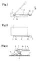
- Figs. 1 to 3 show a sensor device for tire according to a first embodiment of the present invention.
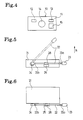
- Fig. 4 exemplifies a sensor unit.
- the sensor device for tire of this embodiment detects tire inside information in a state of the device installed in a tire air chamber, and transmits the detected results to the outside.
- the sensor device for tire includes: a case 1 which houses electronic parts; and a rod-shaped movable member 2 which extends outside the case 1, and is swingable outwardly in a tire radial direction (a direction of the arrow R) by centrifugal force of the tire when the tire is rotating.
- This movable member 2 also functions as an antenna.
- a replaceable weight 3 is attached to a tip 2a of the movable member 2.
- the movable member 2 is supported so as to be swingable around a rotating shaft 4 parallel to a tire axial direction.
- a switch 5 is provided in the vicinity of a base 2b of the movable member 2. This switch 5 is turned on by allowing a movable terminal to come into contact with a fixed terminal.
- a pressing member 6 for pressing the movable terminal of the switch 5 is provided on the rotating shaft 4.
- An elastic body 7 made of a spring is attached around the rotating shaft 4. This elastic body 7 has one end fixed and the other end abutting on the pressing member 6.
- the movable member 2 is energized in a direction opposite to a direction of action of the centrifugal force, that is, toward the bottom of the case 1.
- Elastic force to the movable member 2 by the elastic body 7 may be not less than gravity on the movable member 2 and the weight 3 during stopping. Accordingly, the movable member 2 is folded during stopping. Thus, malfunction of the switch 5 can be prevented.
- a sensor unit 10 as shown in Fig. 4 is housed.
- This sensor unit 10 includes electronic parts such as a sensor 12, a transmitter 13, a battery 14 and a control circuit 15, all of which are mounted on a printed circuit board 11.
- the antenna formed of the movable member 2 is electrically connected to electronic parts included in the transmitter 13.
- the sensor unit 10 measures a tire air pressure by use of the pressure sensor, measures a temperature inside the tire by use of the temperature sensor, and transmits the measured results to the outside of the tire through the antenna formed of the movable member 2.
- the control circuit 15 controls operations of the sensor 12 and the transmitter 13.
- the control circuit 15 can perform the following control. Specifically, in a traveling mode, detection by the sensor 12 is performed at 10-second intervals, and transmission by the transmitter 13 is performed at 1-minute intervals. Meanwhile, in a non-traveling mode, detection by the sensor 12 is performed at 30-minute intervals, and transmission by the transmitter 13 is performed at 60-minute intervals. Accordingly, the control circuit 15 receives detected results of the switch 5, and, based on the detected results, switches at least one of the operations of the sensor 12 and the transmitter 13 between the traveling mode and the non-traveling mode. Specifically, the control circuit 15 selects the traveling mode when the switch 5 detects a traveling state, and selects the non-traveling mode when the switch 5 does not detect the traveling state.
- the control circuit 15 switches at least one of the operations of the sensor 12 and the transmitter 13 between the high frequency traveling mode and the low frequency non-traveling mode. As a result, unnecessary detection and transmission can be omitted to extend life of the battery.
- the movement of the movable member 2 can be controlled externally. For example, by replacing the weight 3 attached to the tip 2a of the movable member 2 with another weight having a different degree of weight, a traveling speed at which the switch 5 is operated can be adjusted. Moreover, by changing the elastic force to the movable member 2 by the elastic body 7, the traveling speed at which the switch 5 is operated can be adjusted. Therefore, sensitivity of the switch 5 can be adjusted according to a wheel structure and an attachment position of the sensor device.
- the weight 3 and the elastic body 7 may be adjusted so as to make it easier for the movable member 2 to swing by the centrifugal force.
- the weight 3 and the elastic body 7 may be set so as to make it difficult for the movable member 2 to swing by the centrifugal force.
- the movable member 2 forms the antenna, the antenna rises outwardly in the tire radial direction by the centrifugal force of the tire when the tire is rotating. Thus, excellent transmission ability can be achieved. Meanwhile, since the movable member 2 is folded by the elastic force of the elastic body 7 during stopping, a rim assembly operation will never be inhibited.
- Figs. 5 and 6 show a sensor device for tire according to a second embodiment of the present invention.
- the sensor device for tire of this embodiment detects tire inside information in a state of the device installed in a tire air chamber, and transmits the detected results to the outside.
- the sensor device for tire includes: a case 21 which houses electronic parts; and a rod-shaped movable member 22 which extends outside the case 21, and is swingable outwardly in a tire radial direction (a direction of the arrow R) by centrifugal force of the tire when the tire is rotating.
- This movable member 22 also functions as an antenna.
- a replaceable weight 23 is attached to a tip 22a of the movable member 22.
- a sensor unit similar to that described above is housed.
- the movable member 22 is supported so as to be swingable around a rotating shaft 24 parallel to a tire axial direction.
- a magnet 28 is attached in an intermediate position between the tip 22a of the movable member 22 and a base 22b thereof.
- a switch 25 is provided in a position facing the magnet 28.
- This switch 25 is a sealed reed switch. Note that an unillustrated elastic body is attached around the rotating shaft 24.
- the movable member 22 is energized in a direction opposite to a direction of action of the centrifugal force.
- the control circuit 15 switches at least one of the operations of the sensor 12 and the transmitter 13 between the high frequency traveling mode and the low frequency non-traveling mode.
- the movement of the movable member 22 can be controlled externally, as in the case of the movable member 2 described above. Therefore, sensitivity of the switch 25 can be adjusted according to a wheel structure and an attachment position of the sensor device.
- the movable member 22 forms an antenna, the antenna rises outwardly in the tire radial direction by the centrifugal force of the tire when the tire is rotating. Thus, excellent transmission ability can be achieved. Meanwhile, since the movable member 22 is folded during stopping, a rim assembly operation will never be inhibited.
- the switch 25 is the sealed reed switch operated by the magnet 28, contamination of a contact thereof is prevented, and the switch 25 can be operated with accuracy for a long period of time.
- a sensor device for tire which detects tire inside information in a state of the device installed in a tire air chamber and transmits the detected results to the outside, includes: a movable member swingable outwardly in a tire radial direction by centrifugal force of the tire when the tire is rotating; and a switch which detects a traveling state in conjunction with movement of the movable member.
- a switch which detects a traveling state in conjunction with movement of the movable member.
Landscapes
- Engineering & Computer Science (AREA)
- Mechanical Engineering (AREA)
- Arrangements For Transmission Of Measured Signals (AREA)
- Measuring Fluid Pressure (AREA)
Abstract
Description
Claims (9)
- A sensor device for tire which detects tire inside information in a state of the device installed in a tire air chamber and transmits the detected results to the outside, comprising:a movable member which is swingable outwardly in a tire radial direction by centrifugal force of the tire when the tire is rotating; anda switch which detects a traveling state in conjunction with movement of the movable member.
- A sensor device for tire which detects tire inside information in a state of the device installed in a tire air chamber and transmits the detected results to the outside, comprising:wherein the control circuit switches at least one of the operations of the sensor and the transmitter between a traveling mode and a non-traveling mode, based on detected results of the switch.a sensor which detects the tire inside information;a transmitter which transmits the tire inside information;a control circuit which controls operations of the sensor and the transmitter;a battery to be a power source;a movable member which is swingable outwardly in a tire radial direction by centrifugal force of the tire when the tire is rotating; anda switch which detects a traveling state in conjunction with movement of the movable member,
- The sensor device for tire according to any one of claims 1 and 2, wherein the movable member forms an antenna for transmission.
- The sensor device for tire according to any one of claims 1 to 3, wherein the movable member is supported so as to be swingable around a rotating shaft parallel to a tire axial direction, and the switch is disposed in the vicinity of a base of the movable member.
- The sensor device for tire according to any one of claims 1 to 3, wherein the movable member is supported so as to be swingable around a rotating shaft parallel to a tire axial direction, and the switch is disposed in an intermediate position between the base of the movable member and a tip thereof.
- The sensor device for tire according to any one of claims 1 to 5, wherein the movable member is energized by an elastic body in a direction opposite to a direction of action of the centrifugal force.
- The sensor device for tire according to any one of claims 1 to 6, wherein elastic force to the movable member by the elastic body is set to be changeable.
- The sensor device for tire according to any one of claims 1 to 7, wherein a replaceable weight is attached to the tip of the movable member.
- The sensor device for tire according to any one of claims 1 to 8, wherein a magnet is attached to the movable member, and the switch is set to be a sealed reed switch which is operated by the magnet.
Applications Claiming Priority (3)
| Application Number | Priority Date | Filing Date | Title |
|---|---|---|---|
| JP2002361033 | 2002-12-12 | ||
| JP2002361033A JP4121843B2 (en) | 2002-12-12 | 2002-12-12 | Tire sensor device |
| PCT/JP2003/015769 WO2004052664A1 (en) | 2002-12-12 | 2003-12-10 | Sensor device for tire |
Publications (3)
| Publication Number | Publication Date |
|---|---|
| EP1580040A1 true EP1580040A1 (en) | 2005-09-28 |
| EP1580040A4 EP1580040A4 (en) | 2006-04-19 |
| EP1580040B1 EP1580040B1 (en) | 2007-05-02 |
Family
ID=32501025
Family Applications (1)
| Application Number | Title | Priority Date | Filing Date |
|---|---|---|---|
| EP03778764A Expired - Lifetime EP1580040B1 (en) | 2002-12-12 | 2003-12-10 | Sensor device for tire |
Country Status (5)
| Country | Link |
|---|---|
| US (1) | US7299691B2 (en) |
| EP (1) | EP1580040B1 (en) |
| JP (1) | JP4121843B2 (en) |
| DE (1) | DE60313665T2 (en) |
| WO (1) | WO2004052664A1 (en) |
Cited By (1)
| Publication number | Priority date | Publication date | Assignee | Title |
|---|---|---|---|---|
| WO2009063232A1 (en) * | 2007-11-13 | 2009-05-22 | Transense Technologies Plc | Stowable antenna for tpms sensor |
Families Citing this family (4)
| Publication number | Priority date | Publication date | Assignee | Title |
|---|---|---|---|---|
| JP2004299531A (en) * | 2003-03-31 | 2004-10-28 | Yokohama Rubber Co Ltd:The | Sensor device for tire |
| JP4752661B2 (en) | 2006-08-01 | 2011-08-17 | 株式会社デンソー | Transmitter and tire pressure detecting device having the same |
| JP5063404B2 (en) * | 2008-02-25 | 2012-10-31 | 中国電力株式会社 | Connection plug and connection terminal cover |
| JP2011189795A (en) * | 2010-03-12 | 2011-09-29 | Pacific Ind Co Ltd | Tire wear detection device |
Family Cites Families (13)
| Publication number | Priority date | Publication date | Assignee | Title |
|---|---|---|---|---|
| JPS5545513Y2 (en) | 1972-12-27 | 1980-10-24 | ||
| JPS5710530B2 (en) * | 1973-03-06 | 1982-02-26 | ||
| JPS5578512U (en) | 1978-11-25 | 1980-05-30 | ||
| US4531112A (en) * | 1982-06-17 | 1985-07-23 | Thomas Stephen E | Method and apparatus for transmitting from within a pneumatic wheel assembly |
| DE3445854A1 (en) * | 1984-12-15 | 1986-06-19 | Robert Bosch Gmbh, 7000 Stuttgart | Device for monitoring status variables on vehicle tyres |
| JPH0527644U (en) | 1991-09-19 | 1993-04-09 | 株式会社東海理化電機製作所 | Tire pressure sensor used for tire pressure monitoring device |
| US5325901A (en) | 1992-10-06 | 1994-07-05 | Hughes Aircraft Company | Vehicle wheel incorporating tire air pressure sensor |
| JPH10504783A (en) | 1994-08-31 | 1998-05-12 | オター コントロールズ リミテッド | Tire condition monitoring system |
| DE69431127T2 (en) | 1994-11-22 | 2003-03-27 | Schrader-Bridgeport International, Inc. | TIRE PRESSURE MONITORING SYSTEM REMOTE |
| JP3459541B2 (en) | 1997-07-02 | 2003-10-20 | トヨタ自動車株式会社 | Vehicle tire pressure detector |
| EP0979743A1 (en) * | 1998-08-10 | 2000-02-16 | Huang, Tien-Tsai | Pressure gauge having an energy-saving switch assembly for a pressure responsive signal-generating device |
| US6031450A (en) * | 1999-02-03 | 2000-02-29 | Huang; Tien-Tsai | Tire pressure alarm system with centrifugal force-controlled power switch |
| JP2001264202A (en) | 2000-03-15 | 2001-09-26 | Pacific Ind Co Ltd | Tire inflation pressure sensor |
-
2002
- 2002-12-12 JP JP2002361033A patent/JP4121843B2/en not_active Expired - Fee Related
-
2003
- 2003-12-10 WO PCT/JP2003/015769 patent/WO2004052664A1/en not_active Ceased
- 2003-12-10 EP EP03778764A patent/EP1580040B1/en not_active Expired - Lifetime
- 2003-12-10 US US10/538,301 patent/US7299691B2/en not_active Expired - Fee Related
- 2003-12-10 DE DE60313665T patent/DE60313665T2/en not_active Expired - Fee Related
Cited By (1)
| Publication number | Priority date | Publication date | Assignee | Title |
|---|---|---|---|---|
| WO2009063232A1 (en) * | 2007-11-13 | 2009-05-22 | Transense Technologies Plc | Stowable antenna for tpms sensor |
Also Published As
| Publication number | Publication date |
|---|---|
| US20060243041A1 (en) | 2006-11-02 |
| EP1580040A4 (en) | 2006-04-19 |
| JP2004189148A (en) | 2004-07-08 |
| DE60313665D1 (en) | 2007-06-14 |
| JP4121843B2 (en) | 2008-07-23 |
| WO2004052664B1 (en) | 2004-08-12 |
| US7299691B2 (en) | 2007-11-27 |
| DE60313665T2 (en) | 2007-12-27 |
| EP1580040B1 (en) | 2007-05-02 |
| WO2004052664A1 (en) | 2004-06-24 |
Similar Documents
| Publication | Publication Date | Title |
|---|---|---|
| JP3381194B2 (en) | Transponder and sensor device for detecting and transmitting vehicle tire parameter data | |
| US6031450A (en) | Tire pressure alarm system with centrifugal force-controlled power switch | |
| JP3993824B2 (en) | Low current consumption tire pressure monitoring system | |
| EP1700719B1 (en) | Electronic wireless tire pressure monitoring apparatus | |
| TWI417527B (en) | Tire pressure sensor system with improved sensitivity and power saving | |
| EP1002670B1 (en) | Transmitter and external controller of tire inflation pressure monitor | |
| EP2368724B1 (en) | Tire wear detection device | |
| CA2646772A1 (en) | Apparatus for transmitting stored data and engineering conditions of a tire to a remote location | |
| US7299691B2 (en) | Sensor device for tire | |
| EP3165384B1 (en) | Tire state detection device | |
| KR101850638B1 (en) | Wheel assembly rotational position identifying apparatus | |
| US6966220B2 (en) | Device for automatic tire inflation and tire pressure display | |
| KR20080022143A (en) | Automotive Joint | |
| JP4299156B2 (en) | Safety ski binding | |
| CN103648806B (en) | Sending device for sending tire information and tire information monitoring system | |
| US7370522B2 (en) | Sensor system for tire | |
| US5929755A (en) | Pressure gauge having an energy-saving switch assembly for a pressure responsive signal-generating device | |
| US6935169B2 (en) | Tire pressure sensor array | |
| CN215309197U (en) | Injection device | |
| JPH07172120A (en) | Tire pressure detection device | |
| JP2000153703A (en) | Tire-pressure alarm, and control jig capable of arbitrarily manipurating transmission signal | |
| EP1595723A1 (en) | Device for automatic tire inflation and tire pressure display | |
| JPH06219113A (en) | Tire internal pressure detector | |
| EP0979743A1 (en) | Pressure gauge having an energy-saving switch assembly for a pressure responsive signal-generating device | |
| JPH07172119A (en) | Tire pressure detection device |
Legal Events
| Date | Code | Title | Description |
|---|---|---|---|
| PUAI | Public reference made under article 153(3) epc to a published international application that has entered the european phase |
Free format text: ORIGINAL CODE: 0009012 |
|
| 17P | Request for examination filed |
Effective date: 20050706 |
|
| AK | Designated contracting states |
Kind code of ref document: A1 Designated state(s): DE FR GB |
|
| A4 | Supplementary search report drawn up and despatched |
Effective date: 20060302 |
|
| GRAP | Despatch of communication of intention to grant a patent |
Free format text: ORIGINAL CODE: EPIDOSNIGR1 |
|
| GRAS | Grant fee paid |
Free format text: ORIGINAL CODE: EPIDOSNIGR3 |
|
| GRAA | (expected) grant |
Free format text: ORIGINAL CODE: 0009210 |
|
| AK | Designated contracting states |
Kind code of ref document: B1 Designated state(s): DE FR GB |
|
| REG | Reference to a national code |
Ref country code: GB Ref legal event code: FG4D |
|
| REF | Corresponds to: |
Ref document number: 60313665 Country of ref document: DE Date of ref document: 20070614 Kind code of ref document: P |
|
| ET | Fr: translation filed | ||
| PLBE | No opposition filed within time limit |
Free format text: ORIGINAL CODE: 0009261 |
|
| STAA | Information on the status of an ep patent application or granted ep patent |
Free format text: STATUS: NO OPPOSITION FILED WITHIN TIME LIMIT |
|
| 26N | No opposition filed |
Effective date: 20080205 |
|
| PGFP | Annual fee paid to national office [announced via postgrant information from national office to epo] |
Ref country code: GB Payment date: 20071205 Year of fee payment: 5 Ref country code: FR Payment date: 20071210 Year of fee payment: 5 |
|
| PGFP | Annual fee paid to national office [announced via postgrant information from national office to epo] |
Ref country code: DE Payment date: 20071206 Year of fee payment: 5 |
|
| GBPC | Gb: european patent ceased through non-payment of renewal fee |
Effective date: 20081210 |
|
| REG | Reference to a national code |
Ref country code: FR Ref legal event code: ST Effective date: 20090831 |
|
| PG25 | Lapsed in a contracting state [announced via postgrant information from national office to epo] |
Ref country code: DE Free format text: LAPSE BECAUSE OF NON-PAYMENT OF DUE FEES Effective date: 20090701 |
|
| PG25 | Lapsed in a contracting state [announced via postgrant information from national office to epo] |
Ref country code: GB Free format text: LAPSE BECAUSE OF NON-PAYMENT OF DUE FEES Effective date: 20081210 |
|
| PG25 | Lapsed in a contracting state [announced via postgrant information from national office to epo] |
Ref country code: FR Free format text: LAPSE BECAUSE OF NON-PAYMENT OF DUE FEES Effective date: 20081231 |