EP1579650B1 - Data transfer from a host server via a tunnel server to a wireless device, and associating a temporary ipv6 address with a temporary ipv4 address for communicating in an ipv4 wireless network with the device - Google Patents
Data transfer from a host server via a tunnel server to a wireless device, and associating a temporary ipv6 address with a temporary ipv4 address for communicating in an ipv4 wireless network with the device Download PDFInfo
- Publication number
- EP1579650B1 EP1579650B1 EP02787302A EP02787302A EP1579650B1 EP 1579650 B1 EP1579650 B1 EP 1579650B1 EP 02787302 A EP02787302 A EP 02787302A EP 02787302 A EP02787302 A EP 02787302A EP 1579650 B1 EP1579650 B1 EP 1579650B1
- Authority
- EP
- European Patent Office
- Prior art keywords
- tunnel
- network
- host computer
- server
- communication
- Prior art date
- Legal status (The legal status is an assumption and is not a legal conclusion. Google has not performed a legal analysis and makes no representation as to the accuracy of the status listed.)
- Expired - Lifetime
Links
Images

Classifications
-
- H—ELECTRICITY
- H04—ELECTRIC COMMUNICATION TECHNIQUE
- H04L—TRANSMISSION OF DIGITAL INFORMATION, e.g. TELEGRAPHIC COMMUNICATION
- H04L63/00—Network architectures or network communication protocols for network security
- H04L63/02—Network architectures or network communication protocols for network security for separating internal from external traffic, e.g. firewalls
- H04L63/029—Firewall traversal, e.g. tunnelling or, creating pinholes
-
- H—ELECTRICITY
- H04—ELECTRIC COMMUNICATION TECHNIQUE
- H04L—TRANSMISSION OF DIGITAL INFORMATION, e.g. TELEGRAPHIC COMMUNICATION
- H04L12/00—Data switching networks
- H04L12/28—Data switching networks characterised by path configuration, e.g. LAN [Local Area Networks] or WAN [Wide Area Networks]
- H04L12/46—Interconnection of networks
- H04L12/4633—Interconnection of networks using encapsulation techniques, e.g. tunneling
-
- H—ELECTRICITY
- H04—ELECTRIC COMMUNICATION TECHNIQUE
- H04L—TRANSMISSION OF DIGITAL INFORMATION, e.g. TELEGRAPHIC COMMUNICATION
- H04L45/00—Routing or path finding of packets in data switching networks
- H04L45/52—Multiprotocol routers
-
- H—ELECTRICITY
- H04—ELECTRIC COMMUNICATION TECHNIQUE
- H04L—TRANSMISSION OF DIGITAL INFORMATION, e.g. TELEGRAPHIC COMMUNICATION
- H04L61/00—Network arrangements, protocols or services for addressing or naming
-
- H—ELECTRICITY
- H04—ELECTRIC COMMUNICATION TECHNIQUE
- H04L—TRANSMISSION OF DIGITAL INFORMATION, e.g. TELEGRAPHIC COMMUNICATION
- H04L61/00—Network arrangements, protocols or services for addressing or naming
- H04L61/09—Mapping addresses
- H04L61/25—Mapping addresses of the same type
- H04L61/2503—Translation of Internet protocol [IP] addresses
- H04L61/251—Translation of Internet protocol [IP] addresses between different IP versions
-
- H—ELECTRICITY
- H04—ELECTRIC COMMUNICATION TECHNIQUE
- H04L—TRANSMISSION OF DIGITAL INFORMATION, e.g. TELEGRAPHIC COMMUNICATION
- H04L61/00—Network arrangements, protocols or services for addressing or naming
- H04L61/09—Mapping addresses
- H04L61/25—Mapping addresses of the same type
- H04L61/2503—Translation of Internet protocol [IP] addresses
- H04L61/2521—Translation architectures other than single NAT servers
- H04L61/2528—Translation at a proxy
-
- H—ELECTRICITY
- H04—ELECTRIC COMMUNICATION TECHNIQUE
- H04L—TRANSMISSION OF DIGITAL INFORMATION, e.g. TELEGRAPHIC COMMUNICATION
- H04L63/00—Network architectures or network communication protocols for network security
- H04L63/04—Network architectures or network communication protocols for network security for providing a confidential data exchange among entities communicating through data packet networks
- H04L63/0428—Network architectures or network communication protocols for network security for providing a confidential data exchange among entities communicating through data packet networks wherein the data content is protected, e.g. by encrypting or encapsulating the payload
- H04L63/0442—Network architectures or network communication protocols for network security for providing a confidential data exchange among entities communicating through data packet networks wherein the data content is protected, e.g. by encrypting or encapsulating the payload wherein the sending and receiving network entities apply asymmetric encryption, i.e. different keys for encryption and decryption
-
- H—ELECTRICITY
- H04—ELECTRIC COMMUNICATION TECHNIQUE
- H04L—TRANSMISSION OF DIGITAL INFORMATION, e.g. TELEGRAPHIC COMMUNICATION
- H04L63/00—Network architectures or network communication protocols for network security
- H04L63/08—Network architectures or network communication protocols for network security for authentication of entities
-
- H—ELECTRICITY
- H04—ELECTRIC COMMUNICATION TECHNIQUE
- H04L—TRANSMISSION OF DIGITAL INFORMATION, e.g. TELEGRAPHIC COMMUNICATION
- H04L63/00—Network architectures or network communication protocols for network security
- H04L63/16—Implementing security features at a particular protocol layer
- H04L63/166—Implementing security features at a particular protocol layer at the transport layer
-
- H—ELECTRICITY
- H04—ELECTRIC COMMUNICATION TECHNIQUE
- H04L—TRANSMISSION OF DIGITAL INFORMATION, e.g. TELEGRAPHIC COMMUNICATION
- H04L67/00—Network arrangements or protocols for supporting network services or applications
- H04L67/01—Protocols
- H04L67/04—Protocols specially adapted for terminals or networks with limited capabilities; specially adapted for terminal portability
-
- H—ELECTRICITY
- H04—ELECTRIC COMMUNICATION TECHNIQUE
- H04L—TRANSMISSION OF DIGITAL INFORMATION, e.g. TELEGRAPHIC COMMUNICATION
- H04L67/00—Network arrangements or protocols for supporting network services or applications
- H04L67/50—Network services
- H04L67/55—Push-based network services
-
- H—ELECTRICITY
- H04—ELECTRIC COMMUNICATION TECHNIQUE
- H04L—TRANSMISSION OF DIGITAL INFORMATION, e.g. TELEGRAPHIC COMMUNICATION
- H04L67/00—Network arrangements or protocols for supporting network services or applications
- H04L67/50—Network services
- H04L67/60—Scheduling or organising the servicing of application requests, e.g. requests for application data transmissions using the analysis and optimisation of the required network resources
- H04L67/63—Routing a service request depending on the request content or context
-
- H—ELECTRICITY
- H04—ELECTRIC COMMUNICATION TECHNIQUE
- H04L—TRANSMISSION OF DIGITAL INFORMATION, e.g. TELEGRAPHIC COMMUNICATION
- H04L69/00—Network arrangements, protocols or services independent of the application payload and not provided for in the other groups of this subclass
- H04L69/16—Implementation or adaptation of Internet protocol [IP], of transmission control protocol [TCP] or of user datagram protocol [UDP]
- H04L69/167—Adaptation for transition between two IP versions, e.g. between IPv4 and IPv6
-
- H—ELECTRICITY
- H04—ELECTRIC COMMUNICATION TECHNIQUE
- H04L—TRANSMISSION OF DIGITAL INFORMATION, e.g. TELEGRAPHIC COMMUNICATION
- H04L9/00—Cryptographic mechanisms or cryptographic arrangements for secret or secure communications; Network security protocols
- H04L9/40—Network security protocols
-
- H—ELECTRICITY
- H04—ELECTRIC COMMUNICATION TECHNIQUE
- H04W—WIRELESS COMMUNICATION NETWORKS
- H04W40/00—Communication routing or communication path finding
- H04W40/24—Connectivity information management, e.g. connectivity discovery or connectivity update
-
- H—ELECTRICITY
- H04—ELECTRIC COMMUNICATION TECHNIQUE
- H04L—TRANSMISSION OF DIGITAL INFORMATION, e.g. TELEGRAPHIC COMMUNICATION
- H04L63/00—Network architectures or network communication protocols for network security
- H04L63/02—Network architectures or network communication protocols for network security for separating internal from external traffic, e.g. firewalls
- H04L63/0272—Virtual private networks
-
- H—ELECTRICITY
- H04—ELECTRIC COMMUNICATION TECHNIQUE
- H04W—WIRELESS COMMUNICATION NETWORKS
- H04W4/00—Services specially adapted for wireless communication networks; Facilities therefor
- H04W4/06—Selective distribution of broadcast services, e.g. multimedia broadcast multicast service [MBMS]; Services to user groups; One-way selective calling services
-
- H—ELECTRICITY
- H04—ELECTRIC COMMUNICATION TECHNIQUE
- H04W—WIRELESS COMMUNICATION NETWORKS
- H04W76/00—Connection management
- H04W76/10—Connection setup
-
- H—ELECTRICITY
- H04—ELECTRIC COMMUNICATION TECHNIQUE
- H04W—WIRELESS COMMUNICATION NETWORKS
- H04W8/00—Network data management
- H04W8/26—Network addressing or numbering for mobility support
-
- H—ELECTRICITY
- H04—ELECTRIC COMMUNICATION TECHNIQUE
- H04W—WIRELESS COMMUNICATION NETWORKS
- H04W80/00—Wireless network protocols or protocol adaptations to wireless operation
- H04W80/04—Network layer protocols, e.g. mobile IP [Internet Protocol]
- H04W80/045—Network layer protocols, e.g. mobile IP [Internet Protocol] involving different protocol versions, e.g. MIPv4 and MIPv6
-
- H—ELECTRICITY
- H04—ELECTRIC COMMUNICATION TECHNIQUE
- H04W—WIRELESS COMMUNICATION NETWORKS
- H04W88/00—Devices specially adapted for wireless communication networks, e.g. terminals, base stations or access point devices
- H04W88/14—Backbone network devices
-
- H—ELECTRICITY
- H04—ELECTRIC COMMUNICATION TECHNIQUE
- H04W—WIRELESS COMMUNICATION NETWORKS
- H04W92/00—Interfaces specially adapted for wireless communication networks
- H04W92/02—Inter-networking arrangements
-
- H—ELECTRICITY
- H04—ELECTRIC COMMUNICATION TECHNIQUE
- H04W—WIRELESS COMMUNICATION NETWORKS
- H04W92/00—Interfaces specially adapted for wireless communication networks
- H04W92/16—Interfaces between hierarchically similar devices
- H04W92/24—Interfaces between hierarchically similar devices between backbone network devices
Definitions
- IPv6 addressing What makes the situation more difficult is the desire to implement such systems using IPv6 addressing. Many networks and devices still use IPv4 addresses and do not support IPv6 addressing. Such networks and devices may be outside the control of a service provider. Although ideally all networks and devices involved are simultaneously upgraded to support IPv6 addressing, this is highly unlikely to occur in actual practice. In the meantime, solutions are needed for the transition from IPv4 to IPv6 addressing in systems that push information to wireless communication devices having permanent IPv6 addresses.
- IPv4-to-IPv6 transitioning methods and components are discussed but without emphasis on mobility and wireless networks.
- Host system 102 includes a host computer 108 coupled within a host network 110.
- communications of user information between host computer 108 and wireless communication device 130 is facilitated through serving network 106.
- Communications between host system 102 and serving network 106 may be routed through a conventional firewall 112 and public network 104, which may be the Internet.
- host network 110 is an IPv4-addressed network.
- Public network 104 e.g. the Internet
- Tunnel servers 116 which may or may not be co-located, provide access points into serving network 106 for host computers and may be referred to as access servers.
- Tunnel servers 116 are shown in FIG. 1 to include three (3) tunnel servers 118,120, and 122 (denoted tunnel servers 1, 2, ..., N, respectively), although any suitable number may be utilized in the system.
- Each tunnel server 116 is operative to establish and maintain a Transmission Control Protocol (TCP) connection with host computers when such a connection is requested through network entry point device 114.
- TCP Transmission Control Protocol
- Each tunnel server 116 is also operative to perform a tunneling protocol for establishing tunnel connections with host computers in response to tunnel requests received therefrom.
- TCP Transmission Control Protocol
- host computer 108 and tunnel servers 116 are also operative to encapsulate the datagram protocols based on a Point-to-Point Protocol (PPP) standard.
- PPP Point-to-Point Protocol
- the PPP may be based on the methodology described in "The Point-to-Point Protocol (PPP)", Request For Comments (RFC) 1661, issued in July 1994 by the Internet Engineering Task Force (IETF).
- PPP provides a method for encapsulating datagrams over serial links so that, for example, a PC may connect to the Internet through a telephone line with use of a modem.
Abstract
Description
- The present application relates generally to IPv4-to-IPv6 address transitioning methods and apparatus for systems that "push" information to wireless communication devices.
- There are presently several proposals for pushing information to a wireless communication device in an Internet Protocol (IP) based wireless network. In these networks, wireless devices are not provided with permanent identifiers, but instead are dynamically assigned an IP address from a pool of available addresses. Each time the wireless device makes a network connection, a different IP address is typically assigned to the wireless device.
- Thus, for services attempting to push information to the particular wireless device, it is difficult to address the information since the IP address is not permanent. These proposals do not adequately deal with the problems of how to address the wireless device when pushing information to it, and how to bridge the solution to future third-generation (3G) wireless networks, such as a General Packet Radio Service (GPRS) network. The solutions provided by these proposals involve either creating a proprietary Personal Identification Number (PIN) for each wireless device, or trying to use a phone number (or similar permanent identifier) of the wireless device to contact it over an alternative communication network (e.g. a short messaging service (SMS) over a circuit-switched channel).
- What makes the situation more difficult is the desire to implement such systems using IPv6 addressing. Many networks and devices still use IPv4 addresses and do not support IPv6 addressing. Such networks and devices may be outside the control of a service provider. Although ideally all networks and devices involved are simultaneously upgraded to support IPv6 addressing, this is highly unlikely to occur in actual practice. In the meantime, solutions are needed for the transition from IPv4 to IPv6 addressing in systems that push information to wireless communication devices having permanent IPv6 addresses.
- Documents related to the present application include (1)
PCT International Publication No. WO 02/35794 A2 US 2002/0026527 A1 entitled "Methods And Systems For A Generalized Mobility Solution Using A Dynamic Tunneling Agent" by Das et al.; (3) US Patent Publication No.US 2002/0012320 A1 entitled "Mobile Ad Hoc Extensions For The Internet" by Ogier et al.; and (4) EURESCOM PublicationXP-002233200 - In document (4), IPv4-to-IPv6 transitioning methods and components are discussed but without emphasis on mobility and wireless networks.
- The present invention is set out in the accompanying claims.
- According to a first technical aspect, the IPv6 serving network includes a network entry point device and a plurality of tunnel servers for facilitating the communication of user information between host computers in IPv4 communication networks and the wireless devices. The network entry point device is operative to direct a plurality of tunnel requests from the host computers to the tunnel servers in a distributed manner. Each tunnel server is operative to establish and maintain tunnel connections with host computers and to facilitate the communication of user information between them and their associated wireless devices. Each tunnel server is also operative to perform a dynamic routing protocol (DRP). The DRP is utilized for updating a local routing table to reflect newly established tunnel connections and for broadcasting updated routing table information to other tunnel servers.
- When a host computer detects a connection failure with the serving network, it initiates a new connection with it by sending a new tunnel request through the network entry point device, which directs it to a newly selected and available tunnel server. In accordance with the DRP, the new tunnel server then updates its local routing table and broadcasts updated routing table information to the other tunnel servers. In this way, routes between devices are quickly and easily reestablished after a failure occurs. Preferably, the DRP utilizes "link state advertisements" (LSAs) and is based on an Open Shortest Path First (OSPF) standard. As apparent, the front end of the network is suitably configured to provide for scalability and fault tolerance as well as to serve as an effective IPv4-to-IPv6 address transitioning mechanism.
-
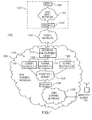
- FIG. 1. is an illustration of a communication system in which a first technical aspect of present application may be embodied, which particularly highlights a front end of a serving network;
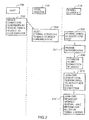
- FIG. 2 is a flow diagram which describes a method of facilitating communication of user information between a host computer and at least one wireless communication device through the serving network of FIG. 1;
- FIG. 3 is another flow diagram associated with FIG. 2 which describes a continued method of facilitating communication of user information between the host computer and the wireless communication device through the serving network of FIG. 1;
- The present application relates to two related methodologies for facilitating the communication of user information from a plurality of host computers to a plurality of wireless communication devices through a serving network. The first technical aspect relates to a front end of the serving network, i.e., a host computer's entry point ar.d connection to the serving network. This first aspect is described below in detail in relation to FIGs. 1-3. The second technical aspect relates to a back end of the serving network, i.e., the exit point from the serving network to a wireless communication device. This second aspect is described below in detail in relation to FIGs. 4-7. Each technical aspect provides an IPv4-to-IPv6 address transitioning mechanism suited particularly for systems that push information to wireless communication devices. Although the first and the second methodologies need not be employed together in the same system, they are preferably utilized in combination in the serving network to exploit their advantages.
- Referring now to FIG.1, an illustration of a
computer system 100 which highlights the components involved in the first technical aspect of the present application, which relates to the serving network's "front end", is shown.Computer system 100 generally includes ahost system 102 and aserving network 106 which communicate through apublic network 104 to provide communications for at least onewireless communication device 130. -
Host system 102 includes ahost computer 108 coupled within a host network 110. In general, communications of user information betweenhost computer 108 andwireless communication device 130 is facilitated through servingnetwork 106. Communications betweenhost system 102 and servingnetwork 106 may be routed through aconventional firewall 112 andpublic network 104, which may be the Internet. In the present embodiment, host network 110 is an IPv4-addressed network. Public network 104 (e.g. the Internet) may also be an IPv4-addressed network or have components thereof (e.g. routers) that are not yet equipped to handle IPv6 addressing. -
Host computer 108 has an application program for receiving user information, processing the user information, and displaying the processed information to the end-user. The user information may be received athost computer 108 by, for example, manual entry through a keyboard or other user suitable interface device inhost system 102. This information may be visually displayed inhost system 102 on a computer monitor or the like. Preferably, the application program associated withhost computer 108 is an e-mail receiving/sending program and/or a calendar/scheduling program. For example, the application program may include the Microsoft Exchange® program available from Microsoft Corporation, or the Lotus Notes® program available from the Lotus Development Corporation. Microsoft Exchange® is a registered trademark of the Microsoft Corporation, and the Lotus Notes® program is a registered trademark of the Lotus Development Corporation. -
Host computer 108 operates to send such user information towireless communication device 130 through servingnetwork 106. More particularly, when new and/or updated information is received by the application program,host computer 108 operates to "push" user information towireless communication device 130 through servingnetwork 106. Conversely,host computer 108 operates to receive new and/or updated information fromwireless communication device 130 and to accordingly update the application program for the end-user. Preferably,wireless communication device 130 operates an application program (e.g. e-mail and/or calendar application) similar to the program onhost computer 108 and such that information is synchronized between the devices in real-time. - Preferably,
host computer 108 is configured to act on behalf of a plurality of end-users, each of which is associated with a particular wireless communication device. For example, a plurality of personal computers (PC) may be connected to host network 110 and access a network server which may run the application program (e.g. the e-mail program or calendaring program). When new and/or updated information from these programs is received,host computer 108 operates to "push" this information to the appropriate wireless communication device through servingnetwork 106. Preferably,host computer 108 initiates the pushing of information substantially in real time, as the information is received or updated. Similarly,host computer 108 operates to receive user information from each one of the wireless communication devices and to update data for the appropriate end-user for the application program. - Although not shown in FIG.1 for simplicity and clarity, additional host systems like
host system 102 communicate with other wireless communication devices through servingnetwork 106 as well. Such a host system or host computer may be part of a private network or, alternatively, part of a public network. - Referring now to serving
network 106 of FIG. 1, a "front end"subnetwork 124 includes a networkentry point device 114, a plurality oftunnel servers 116, and arouter 126.Front end subnetwork 124 is coupled to a "core" servingnetwork 128 throughrouter 126. Networkentry point device 114 and devices in front end subnetwork 124 (e.g. tunnel servers 116) are part of what may be referred to as a "host access network".Core network 128, as its name suggests, is the central core of servingnetwork 106 which helps facilitate the communication of user information to and fromwireless communication device 130 through a wireless communication network (not shown in FIG. 1). The dividing point between the front end and the remaining part of servingnetwork 106 is marked byrouter 126, which routes communications betweenfront end subnetwork 126 andcore network 128. In contrast to host network 110 and/orpublic network 104, serving network 106 (which includes core network 128) is an IPv6 addressed network. - Network
entry point device 114 is any device which serves the front end of servingnetwork 106 in order to at least receive and handle initial host requests. Networkentry point device 114 appropriately directs communications between devices inpublic network 104 andtunnel servers 116. In simplest form, networkentry point device 114 may be viewed as a switch which helps to facilitate multiple connections between hosts and servers. Preferably, networkentry point device 114 is a traffic directing device which receives requests from multiple hosts, distributes the requests amongst multiple servers in the network, and directs subsequent traffic to and from them appropriately. - More preferably, network
entry point device 114 is a local director. A local director is a traffic directing device which distributes host requests amongst multiple servers of the network in a load balanced manner, taking into account the availability/unavailability of the servers, and thereafter directs traffic to and from them appropriately. Load balancing techniques evenly distribute connections across multiple servers, giving preference to those servers with the least amount of congestion or use. One local director which may be used is a LocalDirector device which is available from Cisco Systems, Inc., of San Jose, California, U.S.A. - In an alternate embodiment, network
entry point device 114 is a domain name server (DNS) which uses a round-robin assignment technique. In general, round robin DNS also distributes connection loads across multiple servers. In contrast to a local director methodology, round robin works on a rotating basis such that one server IP address is handed out and placed at the back of the address list, the next server IP address is handed out and placed at the back end of the list, and so on depending on the number of servers being used. This is performed in a continuous loop fashion; the order of assignment is fairly rigid and does take into account the actual loading of each server or its availability. -
Tunnel servers 116, which may or may not be co-located, provide access points into servingnetwork 106 for host computers and may be referred to as access servers.Tunnel servers 116 are shown in FIG. 1 to include three (3) tunnel servers 118,120, and 122 (denotedtunnel servers tunnel server 116 is operative to establish and maintain a Transmission Control Protocol (TCP) connection with host computers when such a connection is requested through networkentry point device 114. Eachtunnel server 116 is also operative to perform a tunneling protocol for establishing tunnel connections with host computers in response to tunnel requests received therefrom. - Tunneling is a method of communicating data between two networks that use different and oftentimes incompatible communication protocols. Tunneling typically involves encapsulating data packets at a source device in one network to provide compatibility when delivered through the other network to a destination device, where the packets are decapsulated to reveal the underlying data packets. In
communication system 100, a tunnel connection is established between one oftunnel servers 116 andhost computer 108 for connecting the front end of serving network 106 (which is an IPv6 addressed network) to host network 110 (which is an IPv4 addressed network). Once a tunnel server is selected and a tunnel connection is established between a host and the selected tunnel server, network entry point device 114 (e.g. as a local director) performs a Network Address Translation (NAT) function between the host and the tunnel server to facilitate ongoing communications therebetween. - Preferably, each
tunnel server 116 is operate to establish and maintain secure tunnel connections in accordance with a Secure Shell (SSH) standard. Such a security protocol may be based on a version of SSH1 or SSH2, or alternatively based on an open SSH standard called OpenSSH developed by the OpenBSD Project (Berkley Software Distribution) such as OpenSSH Version 3.4, June 26, 2002. There are a number of references available on SSH, including the book entitled " SSH: The Secure Shell, The Definitive Guide" by Daniel J. Barrett, PhD., and Richard E. Silverman. In general, SSH is a software tool and protocol for secure remote login over networks. It provides an encrypted terminal session with strong authentication of both server and client using public-key cryptography. The features supported with SSH include a variety of user authentication methods; tunneling arbitrary TCP connections through the SSH session; protecting normally insecure protocols (such as Internet Mail Application Protocol or IMAP) and allowing secure passage through firewalls; automatic forwarding of X Windows connections; support for external authentication methods, (including Kerberos and SecurID); and secure file transfers. - In particular, a first level of SSH authentication allows any host to connect to a SSH server as long as the password of the account at the server is known. This procedure will encrypt traffic sent via SSH, but it does not in itself provide a strong mechanism to authenticate the host. A second level of SSH authentication relies on a security key mechanism: a key pair is created and the public key is provided to the server. When connecting to an SSH server, the host sends a request to the server for authentication with use of the security keys. The server looks up the public key in a remote home directory at the server and compares both keys. It then sends an encrypted "challenge" to the host, which is decrypted at the host with the private key and sent back to the server.
- As an alternative to SSH, each
tunnel server 116 may operate to establish and maintain secure tunnel connections in accordance with Virtual Private Network (VPN) techniques. Such techniques may include a Point-To-Point Tunneling Protocol (PPTP), aLayer 2 Tunneling Protocol (L2TP), and IP Secure Protocol (IPsec), as some examples. - Preferably,
host computer 108 andtunnel servers 116 are also operative to encapsulate the datagram protocols based on a Point-to-Point Protocol (PPP) standard. For example, the PPP may be based on the methodology described in "The Point-to-Point Protocol (PPP)", Request For Comments (RFC) 1661, issued in July 1994 by the Internet Engineering Task Force (IETF). In general, PPP provides a method for encapsulating datagrams over serial links so that, for example, a PC may connect to the Internet through a telephone line with use of a modem. PPP also provides a Link Control Protocol (LCP) for establishing, configuring, and testing the data-link connection, as well as a family of Network Control Protocols (NCPs) for establishing and configuring different network-layer protocols. PPP session establishment also utilizes three phases which include a link establishment phase, an (optional) authentication phase, and a network-layer protocol phase, which use known methodologies. Together, as apparent from the above-description, the preferable connection betweenhost computer 108 and a tunnel server is a "tunneled PPP over SSH over TCP" connection. -
Tunnel servers 116 androuter 126 are also operative to perform dynamic routing functions for the front end of servingnetwork 106. Preferably, these routing functions include a dynamic routing protocol (DRP) utilized infront end subnetwork 124. Conventionally, a "dynamic" routing of data through a network exploits the likelihood that the appropriate or best route for sending data packets between two devices through a network may change over time. A dynamic routing protocol is a protocol utilized in network routing devices for automatically and regularly determining, updating, and communicating within the network what the appropriate or best routes are between network devices, so that these routes may be used when data packets are sent through the network. - For use in connection with the DRP, each one of
tunnel servers 116 androuter 126 has a local routing table in its memory which associates an IP address of a destination device with an IP address of an appropriate or best adjacent routing device. Per the DRP, when connections change, updates are made to the local routing tables through broadcasts by the routing devices. If a new tunnel connection is established betweentunnel server 118 andhost computer 108, for example,tunnel server 118 updates its local routing table to reflect the new relationship. It then broadcasts the updated routing table information to theother tunnel servers 116 androuter 126 so that, for example,router 126 will direct user information destined tohost computer 108 throughtunnel server 118. - Preferably, the DRP is based on an Open Shortest Path First (OSPF) standard developed by the IETF. OSPF is generally classified as an Internal Gateway Protocol (IGP) as it is designed to distribute routing information between routers of a single autonomous system. OSPF is a link-state algorithm which specifies a class of messages called link-state advertisements (LSAs) which are used by routers to update each other about the network links. Link-state updates are stored in a topology database which contains a representation of every link and router in the network One current standard for OSPF is
OSPF Version 2 developed by the IETF and documented in RFC 1247, July 1991. Using such a DRP, updates to routing tables are made periodically (e.g. every 30 minutes) as well as when a link change is observed in the network. - Although use of OSPF is advantageous, any other suitable dynamic routing protocol may be utilized. A Routing Information Protocol (RIP) or a Border Gateway Protocol (BGP), as examples, may deemed suitable depending on the implementation. In contrast to OSPF, RIP utilizes a distance-vector algorithm where each router precomputes the best links and broadcasts its entire routing database periodically (e.g. every 30 seconds) to all other routers in the network. One current standard for RIP is
RIP Version 2 developed by the IETF and documented in RFC 2453, November 1998. One current standard for BGP, which is based on a most specific prefix and shortest Autonomous System (AS) path, is BGP Version 4 developed by the IETF and documented in RFC 1771. - FIGs. 2 and 3 are flow diagrams which are used to describe a method of facilitating communication of user information between a host computer and a wireless communication device through a serving network. Such methods may be utilized in connection with
host computer 108, servingnetwork 106, andwireless communication device 130 of FIG. 1. More particularly, FIG. 2 relates to an initial connection setup between a host computer and a serving network; FIG. 3 relates to communication of user information, detection of a communication failure, and a connection reestablishment between the host computer and the serving network. Such methods may be embodied in a computer program product which includes a computer storage medium and computer instructions stored on the computer storage medium, where the computer instructions can be executed to perform the methods. - In the following description of the flow diagram of FIG. 2, FIGs. 1-2 are referred to in combination.
Host computer 108 initiates a connection to servingnetwork 106 by sending a tunnel request to network entry point device 114 (step 202 of FIG. 2). Networkentry point device 114 receives this request fromhost computer 108 and, in response, selects one of the plurality oftunnel servers 116 to which to direct communications with host computer 108 (step 204 of FIG. 2). In the present example, networkentry point device 114 particularly selectstunnel server 118 to which to direct communications withhost computer 108.Tunnel server 118 receives this tunnel request fromhost computer 108 through network entry point device 114 (step 206 of FIG. 2). In response to receiving the tunnel request,tunnel server 118 provides any necessary authentication (step 207 of FIG. 2) and establishes a tunnel connection with host computer 108 (step 208 of FIG. 2) assuming the authentication is successful. - Although described above as involving a
single host computer 108, steps 202-208 described in relation to FIG. 2 are actually performed contemporaneously in connection with a plurality of host computers which, over some period of time, send a plurality of tunnel requests through networkentry point device 114. Accordingly, networkentry point device 114 performs selection of a tunnel server instep 204 in a manner such that all tunnel connections are distributed amongst all tunnel servers 116 (using, for example, a round robin DNS or a local director). Preferably, the distribution is performed in a substantially evenly or equal manner amongst alltunnel servers 116 that are available (using, for example, the local director). This selection may be performed in networkentry point device 114 utilizing conventional load balancing techniques. - The tunnel connection established in
step 208 is a "long live" connection which is utilized to facilitate the communication of user information betweenhost computer 108 andwireless communication device 130, as well as betweenhost computer 108 and any other wireless communication devices associated with the application program inhost system 102. In the present embodiment, the tunnel connection established instep 208 has connection points athost computer 108 andtunnel server 118 for connecting host network 110 (an IPv4-addressed network) to the front end of serving network 106 (an IPv6-addressed network). When sending data packets fromhost computer 108 towireless communication device 130 throughtunnel server 118, the tunneling protocol athost computer 108 involves "wrapping" or encapsulating IPv6-addressed data packets (i.e. addressed to wireless communication device 130) within IPv4-addressed data packets. Whentunnel server 118 receives these data packets fromhost computer 108, the tunneling protocol attunnel server 118 involves "unwrapping" or decapsulating the IPv4-addressed data packets to reveal the underlying IPv6-addressed data packets. These IPv6-addressed data packets are subsequently sent towireless communication device 130 throughrouter 126 andcore subnetwork 128. - Conversely, data packets are also sent from
wireless communication device 130 tohost computer 108 throughtunnel server 118 over the tunnel connection. In this case,tunnel server 118 receives IPv6-addressed data packets (i.e. addressed to host computer 108) fromwireless communication device 130. The tunneling protocol attunnel server 118 involves wrapping or encapsulating these IPv6-addressed data packets within IPv4-addressed data packets. Whenhost computer 108 receives these data packets, the tunneling protocol athost computer 108 involves unwrapping or decapsulating the IPv4-addressed data packets to reveal the underlying IPv6-addressed data packets. User information in these underlying data packets are subsequently directed for storage with the appropriate end-user data associated with that address. - As described earlier above,
tunnel server 118 is also configured to perform a dynamic routing protocol (DRP) infront end subnetwork 124. Thus, after establishing the tunnel connection instep 208 of FIG. 2,tunnel server 118 uses its DRP to update its local routing table to reflect the new tunnel connection (step 210 of FIG. 2). The update to the local routing table attunnel server 118 involves storing an IP address oftunnel server 118 in association with a destination IP address tohost computer 108.Tunnel server 118 also uses the DRP to broadcast this updated routing table information to allother tunnel servers 116 androuter 126. The broadcasting of updated routing table information may be performed in response to identifying a newly established connection, or it may be performed periodically over time, or both. When updated routing table information is broadcasted fromtunnel server 118 and received atother tunnel servers 116 androuter 126,other tunnel servers 116 androuter 126 update their own local routing tables to reflect the new tunnel connection. - In this way, when a communication of user information intended for
host computer 108 is received atrouter 126, for example,router 126 examines its local routing table to identify thattunnel server 118 is responsible for communications withhost computer 108. Thus,router 126 routes the user information totunnel server 118 so thattunnel server 118 may communicate it tohost computer 108 over the tunnel connection. - With the entry point connection now established, basic steady-state operation is now described in relation to FIG. 3.
Host computer 108 initiates a "pushing" of new and/or updated user information (e.g. e-mail information) towireless communication device 130 by sending this information totunnel server 118 over the tunnel connection (step 302 of FIG. 3).Tunnel server 118 receives this new and/or updated information over the tunnel connection through networkentry point device 114.Tunnel server 118 facilitates the communication of the new and/or updated user information towireless communication device 130 over the tunnel connection (step 304 of FIG. 3), executing its tunneling protocols and appropriately routing the information. - However, there are times when the connection between
host computer 108 andtunnel server 118 may fail or otherwise become unavailable. For example,tunnel server 118 may be intentionally taken "off-line", lose supply power, exhibit a technical failure, or become excessively loaded; or the communication channel or tunnel connection may itself be interrupted by interference or some other disruption. Thus, a communication failure or unavailable connection betweenhost computer 108 and tunnel server.118 may exist, as is illustrated in FIG. 3 at apoint 350. -
Host computer 108 is configured to detect such a communication failure between it and tunnel server 118 (step 306 of FIG. 3). This detection may be performed in any number of suitable ways. For example, afterhost computer 108 attempts to send data packets through servingnetwork 106, it may detect such a condition in response to failing to receive an acknowledgement or response, or receiving a "Destination Unreachable", "Message Undeliverable", or "Server Unavailable" message. As another example,host computer 108 may detect such a condition in response to failing to receive one or more "heartbeats" or "keep alive" messages fromtunnel server 118 which are otherwise regularly or periodically sent. - In response to detecting the communication failure,
host computer 108 attempts to reinitiate or reestablish a connection with servingnetwork 106.Host computer 108 does this by sending a tunnel request through network entry point device 114 (step 308 of FIG. 3). In general, thisstep 308 uses the same process performed instep 202 of FIG. 2. Networkentry point device 114 receives this request fromhost computer 108 and, in response, selects one of the plurality oftunnel servers 116 to which to direct communications with host computer 108 (step 310 of FIG. 3). In the present example, networkentry point device 114 particularly selects tunnel server 120 (nottunnel server 118 where communication is no longer possible) to which to direct communications withhost computer 108. - Thus,
tunnel server 120 receives this new tunnel request fromhost computer 108 through network entry point device 114 (step 312 of FIG. 3). In response to receiving the tunnel request,tunnel server 120 establishes a tunnel connection with host computer 108 (step 314 of FIG. 3) after performing a successful authentication procedure. The tunnel connection established instep 314 is a "long live" connection used to facilitate the communication of user information betweenhost computer 108 andwireless communication device 130, as well as betweenhost computer 108 and any other wireless communication devices associated with the application program inhost system 102. - As with each one of
tunnel servers 116,tunnel server 120 is configured to perform the DRP infront end subnetwork 124. Thus,tunnel server 120 uses its DRP to update its local routing table to reflect the newly established tunnel connection (step 316 of FIG. 3). The update to the local routing table attunnel server 120 involves storing an IP address oftunnel server 120 in association with a destination IP address tohost computer 108.Tunnel server 120 also uses the DRP to broadcast updated routing table information to allother tunnel servers 116 and router 126 (step 318 of FIG. 3). The broadcasting of routing table information may be performed in response to identifying a newly established connection, or it may be performed periodically over time, or both. When updated routing table information is broadcasted fromtunnel server 120 and received atother tunnel servers 116 androuter 126, theother tunnel servers 116 androuter 126 update their own local routing tables to reflect the new tunnel connection. In general, steps 312-318 of FIG. 3 use the same processes as steps 206-212 of FIG. 2, except that steps 312-318 are shown as being performed bytunnel server 120 rather thantunnel server 118. - In this way, when a communication of user information from
wireless communication device 130 forhost computer 108 is received atrouter 126, for example,router 126 examines its local routing table to identify thattunnel server 120 is now responsible for communications withhost computer 108. Thus,router 126 routes the user information totunnel server 120 so thattunnel server 120 may communicate it tohost computer 108 over the newly established tunnel connection. Also,host computer 108 may again initiate a "pushing" of new and/or updated user information (e.g. e-mail information) towireless communication device 130 by sending such information now totunnel server 120 over the tunnel connection.Tunnel server 120 receives this new and/or updated information over the tunnel connection through networkentry point device 114.Tunnel server 120 facilitates the communication of the new and/or updated user information towireless communication device 130 over the tunnel connection, executing its tunneling protocols and appropriately routing the information. - Although the methods described in relation to FIGs. 2 and 3 are described as being performed in connection with a
single host computer 108 andtunnel server 118 /120, each one oftunnel servers 116 is actually configured to contemporaneously maintain other tunnel connections with other host computers in the same manner and use, as well as perform the DRP. Also, the methods are contemporaneously performed between other host computers of other host systems andother tunnel servers 116 in servingnetwork 106. - As apparent from the description of FIGs. 1-3, the front end of the network is advantageously configured to provide for scalability and fault tolerance, as well as for IPv4-to-IPv6 address transitioning, for push-based systems.
- It is to be understood that the above is merely a description of preferred embodiments of the invention and that various changes, alterations, and variations may be made without departing from the scope of the invention as set for in the appended claims. None of the terms or phrases in the specification and claims has been given any special particular meaning different from the plain language meaning to those skilled in the art, and therefore the specification is not to be used to define terms in an unduly narrow sense.
Claims (22)
- A method of facilitating a communication of user information between a host computer (108) and at least one wireless communication device (130) comprising the acts of:receiving, at a tunnel server (118), a tunnel request from a host computer (108) which is distributed through a network entry point device (114);establishing a tunnel connection with the host computer (108) in response to the tunnel request;updating a local routing table to reflect the newly established tunnel connection;broadcasting updated routing table information which reflects the newly established tunnel connection; andfacilitating a communication of user information between the host computer (108) and a wireless communication device (130) through the tunnel connection.
- The method of claim 1, wherein the tunnel server (118) is part of an IPv6 communication network (106) and receives communications from the host computer (108) through an IPv4 communication network (110).
- The method of claim 1, wherein the act of facilitating a communication of user information comprises e-mail information being pushed from the host computer (108) to the at least one wireless communication device (130).
- The method of claim 1, wherein a dynamic routing protocol is used in performing the acts of updating the local routing table and broadcasting the updated routing table information.
- The method of claim 1, wherein a dynamic routing protocol based on an Open Shortest Path First standard is used in performing the acts of updating the local routing table and broadcasting the updated routing table information.
- The method of claim 1, wherein the act of facilitating a communication of user information comprises providing for secure communications over the tunnel connection based on virtual private networking.
- The method of claim 1, wherein the act of facilitating a communication of user information comprises providing for secure communications over the tunnel connection based on a Secure Shell standard.
- The method of claim 1, further comprising the acts of:receiving a new tunnel request from the host computer (108), after the host computer (108) detects a communication failure with the tunnel connection.
- A method of pushing e-mail information from a plurality of host computers (108) to a plurality of wireless communication devices (130) comprising the acts of:providing a communication network (106) which includes a front end subnetwork (124) and a core network (128), the front end subnetwork (124) including a plurality of tunnel servers (118, 120, and 122) coupled to a network entry point device (114) and a router (126) coupled to the core network (128);receiving, at the network entry point device (114), a plurality of tunnel requests from the host computers (108);distributively sending, by the network entry point device (114), the plurality of tunnel requests to the tunnel servers (118,120, and 122);establishing, by the tunnel servers (118, 120, and 122), a plurality of tunnel connections with the host computers (108) in response to the tunnel requests;performing, by each tunnel server (118, 120, and 122) and the router (126), a dynamic routing protocol;updating, by each tunnel server (118, 120, and 122) according to the dynamic routing protocol, a local routing table to reflect the newly established tunnel connections;broadcasting, by each tunnel server (128,120, and 122) according to the dynamic routing protocol, updated routing table information which reflects the newly established tunnel connections to other tunnel servers (118, 120, and 122) and the router (126); andfacilitating the pushing of e-mail information between the host computers (108) and the wireless communication devices (130) through the tunnel connections.
- The method of claim 9, further comprising:receiving, by the network entry point device (114), a new tunnel request from one of the host computers (108) which has detected a communication failure with one of the tunnel servers (218);selecting and directing, by the network entry point device (114), the new tunnel request to a new one of the tunnel servers (120);establishing, by the newly selected tunnel server (120), a new tunnel connection with the host computer (108); andperforming, by the newly selected tunnel server (120), the dynamic routing protocol for updating the local routing table and for broadcasting updated routing table information.
- A communication network (106) for facilitating communications between a plurality of host computers (108) and a plurality of wireless communication devices (130), the communication network (106) comprising:a network entry point device (114);a plurality of tunnel servers (118,120, and 122);the network entry point device (114) being operative to direct a plurality of tunnel requests from a plurality of host computers (108) to the plurality of tunnel servers (118,120, and 122) in a distributed manner;each tunnel server (118, 120, and 122) being operative to establish and maintain a plurality of tunnel connections with host computers (108) in response to tunnel requests received therefrom;each tunnel server (118, 120, and 122) being operative to facilitate a communication of user information between each host computer (108) having a tunnel connection established therewith and at least one wireless communication device (130); andeach tunnel server (118, 120, and 122) being operative to perform a dynamic routing protocol for updating a local routing table to reflect newly established tunnel connections and for broadcasting updated routing table information to the other tunnel servers.
- The communication network (106) of claim 11, wherein the communication network (106) comprises an IPv6 communication network and at least one host computer (108) adapted to communicate through an IPv4 communication network (110).
- The communication network (106) of claim 11, wherein each tunnel server (118, 120, and 122) is operative to facilitate a communication of user information comprising e-mail information being pushed to a wireless communication device (130).
- The communication network (106) of claim 11, wherein the network entry point device (114) comprises a local director for directing said plurality of tunnel requests in a load balanced manner.
- The communication network (106) of claim 11, wherein the network entry point device (114) comprises a domain name server which employs a round-robin assignment technique.
- The communication network (106) of claim 11, wherein each tunnel server (118, 120, and 122) is operative to perform a dynamic routing protocol in accordance with an Open Shortest Path First standard.
- The communication network (106) of claim 11, wherein each tunnel server (118, 120, and 122) is operative to perform a dynamic routing protocol in accordance with an Routing Information Protocol standard.
- The communication network (106) of claim 11, wherein each tunnel server (118, 120, and 122) is operative to provide secure communications with host computers (108) over the tunnel connections.
- The communication network (106) of claim 11, wherein each tunnel server (118, 120, and 122) is operative to provide secure communications with host computers (108) over the tunnel connections in accordance with a Secure Shell standard.
- The communication network (106) of claim 11, further comprising:each host computer (108) being operative to detect a communication failure with a tunnel server; andeach host computer (108) being operative to send a tunnel request for a new tunnel connection through the network entry point device (114) in response to detecting the communication failure.
- The communication network (106) of claim 11, further comprising:a router (126);the router (126) being operative to route communications to the tunnel servers (118,120, and 122); andthe router (126) being operative to perform the dynamic routing protocol with the plurality of tunnel servers (118,120, and 122).
- The communication network (106) of claim 11, further comprising:a router (126);a front end subnetwork (124) which includes the plurality of tunnel servers (118, 120, and 122) and the router (126);a core network (128);the router (126) coupled to the core network (128); andthe router (126) being operative to perform the dynamic routing protocol with the plurality of tunnel servers (118,120, and 122).
Priority Applications (1)
| Application Number | Priority Date | Filing Date | Title |
|---|---|---|---|
| EP06125640A EP1763197B1 (en) | 2002-11-27 | 2002-12-20 | Associating a temporary IPv6 address with a temporary IPv4 address for communicating in an IPv4 network with a wireless device |
Applications Claiming Priority (3)
| Application Number | Priority Date | Filing Date | Title |
|---|---|---|---|
| US42935002P | 2002-11-27 | 2002-11-27 | |
| US429350P | 2002-11-27 | ||
| PCT/CA2002/002012 WO2004049668A1 (en) | 2002-11-27 | 2002-12-20 | Data transfer from a host server via a tunnel server to a wireless device, and associating a temporary ipv6 address with a temporary ipv4 address for communicating in an ipv4 wireless network with the device |
Related Child Applications (1)
| Application Number | Title | Priority Date | Filing Date |
|---|---|---|---|
| EP06125640A Division EP1763197B1 (en) | 2002-11-27 | 2002-12-20 | Associating a temporary IPv6 address with a temporary IPv4 address for communicating in an IPv4 network with a wireless device |
Publications (2)
| Publication Number | Publication Date |
|---|---|
| EP1579650A1 EP1579650A1 (en) | 2005-09-28 |
| EP1579650B1 true EP1579650B1 (en) | 2007-08-15 |
Family
ID=32393548
Family Applications (2)
| Application Number | Title | Priority Date | Filing Date |
|---|---|---|---|
| EP06125640A Expired - Lifetime EP1763197B1 (en) | 2002-11-27 | 2002-12-20 | Associating a temporary IPv6 address with a temporary IPv4 address for communicating in an IPv4 network with a wireless device |
| EP02787302A Expired - Lifetime EP1579650B1 (en) | 2002-11-27 | 2002-12-20 | Data transfer from a host server via a tunnel server to a wireless device, and associating a temporary ipv6 address with a temporary ipv4 address for communicating in an ipv4 wireless network with the device |
Family Applications Before (1)
| Application Number | Title | Priority Date | Filing Date |
|---|---|---|---|
| EP06125640A Expired - Lifetime EP1763197B1 (en) | 2002-11-27 | 2002-12-20 | Associating a temporary IPv6 address with a temporary IPv4 address for communicating in an IPv4 network with a wireless device |
Country Status (9)
| Country | Link |
|---|---|
| US (2) | US7710984B2 (en) |
| EP (2) | EP1763197B1 (en) |
| CN (1) | CN1736077B (en) |
| AT (2) | ATE449493T1 (en) |
| AU (1) | AU2002351629A1 (en) |
| CA (1) | CA2507529C (en) |
| DE (2) | DE60234479D1 (en) |
| HK (2) | HK1079636A1 (en) |
| WO (1) | WO2004049668A1 (en) |
Families Citing this family (107)
| Publication number | Priority date | Publication date | Assignee | Title |
|---|---|---|---|---|
| US7644171B2 (en) * | 2001-09-12 | 2010-01-05 | Netmotion Wireless, Inc. | Mobile networking system and method using IPv4 and IPv6 |
| US7092986B2 (en) * | 2002-02-07 | 2006-08-15 | Institute For Information Industry | Transparent mobile IPv6 agent |
| US20040186878A1 (en) * | 2003-02-21 | 2004-09-23 | Shu Yamamoto | Internet service provider facilitating IPv6 connectivity across a customer's network containing IPv4 components |
| US7379451B1 (en) | 2003-04-21 | 2008-05-27 | Xilinx, Inc. | Address lookup table |
| US7886075B2 (en) * | 2003-05-16 | 2011-02-08 | Cisco Technology, Inc. | Arrangement for retrieving routing information for establishing a bidirectional tunnel between a mobile router and a correspondent router |
| US7746891B2 (en) * | 2003-05-29 | 2010-06-29 | Kddi Corporation | Enabling mobile IPv6 communication over a network containing IPv4 components using ISATAP |
| US20050015497A1 (en) * | 2003-05-29 | 2005-01-20 | Hidetoshi Yokota | Automatic IPv6 connect agent discovery using DNS |
| US7554991B2 (en) * | 2003-06-27 | 2009-06-30 | Nokia Corporation | Method, system and network element for data transmission using a transition mechanism |
| US20050099976A1 (en) * | 2003-09-23 | 2005-05-12 | Shu Yamamoto | Enabling mobile IPv6 communication over a network containing IPv4 components using a tunnel broker model |
| US7554981B2 (en) * | 2003-11-26 | 2009-06-30 | Wind River Systems, Inc. | System and method for efficient storage and processing of IPv6 addresses |
| US9032095B1 (en) | 2004-01-06 | 2015-05-12 | Juniper Networks, Inc. | Routing device having multiple logical routers |
| US20050180319A1 (en) * | 2004-02-18 | 2005-08-18 | Hutnik Stephen M. | Narrowband and broadband VPN optimal path selection using the global positioning system |
| GB2413464A (en) * | 2004-04-21 | 2005-10-26 | Orange Sa | An inter-working unit with a protocol conversion or protocol encapsulation function, for use with dual stack user equipment on a packet radio network |
| JP4423118B2 (en) * | 2004-06-08 | 2010-03-03 | 株式会社エヌ・ティ・ティ・ドコモ | Mobile communication system, access router, management apparatus, and mobile communication method |
| US8849892B2 (en) * | 2004-06-10 | 2014-09-30 | Verizon Patent And Licensing Inc. | Method and system for brokering messages in a distributed system |
| EP1605640A1 (en) * | 2004-06-10 | 2005-12-14 | Alcatel | Network unit for exchanging protocol data units through tunnels |
| DE602004026851D1 (en) * | 2004-07-02 | 2010-06-10 | Alcatel Lucent | Method for establishing a connection between nodes with multiple network capabilities |
| GB2417650A (en) | 2004-07-30 | 2006-03-01 | Orange Personal Comm Serv Ltd | Tunnelling IPv6 packets over IPv4 packet radio network wherein an IPv6 address including a tunnel end identifier of the IPv4 bearer is formed |
| GB2416958A (en) | 2004-07-30 | 2006-02-08 | Orange Personal Comm Serv Ltd | Communicating internet packet data over a packet radio network |
| JP2006074132A (en) * | 2004-08-31 | 2006-03-16 | Matsushita Electric Ind Co Ltd | Multicast communication method and gateway device |
| JP4475514B2 (en) * | 2004-09-02 | 2010-06-09 | Kddi株式会社 | IPv6 / IPv4 tunneling method |
| US7865944B1 (en) * | 2004-09-10 | 2011-01-04 | Juniper Networks, Inc. | Intercepting GPRS data |
| JP2006217096A (en) * | 2005-02-02 | 2006-08-17 | Nec Corp | Movement management system and movement management server, and movement management method and program thereof used for same |
| FI120072B (en) * | 2005-07-19 | 2009-06-15 | Ssh Comm Security Corp | Transmission of packet data over a network with a security protocol |
| KR20070013864A (en) * | 2005-07-27 | 2007-01-31 | 삼성전자주식회사 | Device for channel time reservation conflict avoidance and resolution in wireless distributed mac systems, system comprising the device and method thereof |
| US7810149B2 (en) * | 2005-08-29 | 2010-10-05 | Junaid Islam | Architecture for mobile IPv6 applications over IPv4 |
| US20070074283A1 (en) * | 2005-09-26 | 2007-03-29 | Marian Croak | Method and apparatus for activating alternative virtual private network protocols |
| JP4327142B2 (en) * | 2005-09-29 | 2009-09-09 | パナソニック株式会社 | Information processing system, tunnel communication device, tunnel communication method, proxy response device, and proxy response method |
| KR100749816B1 (en) | 2005-11-02 | 2007-08-16 | 경희대학교 산학협력단 | Method for providing an ability of roaming from IPv6 network based on NEMO to IPv4 network |
| US20070127474A1 (en) * | 2005-12-02 | 2007-06-07 | Cisco Technology, Inc. | Automatic mapping of an IPv6 packet in multi-topology routing |
| GB0601913D0 (en) * | 2006-01-31 | 2006-03-08 | Ericsson Telefon Ab L M | Packet re-direction in a communication network |
| US8589573B2 (en) * | 2006-03-08 | 2013-11-19 | Cisco Technology, Inc. | Technique for preventing routing loops by disseminating BGP attribute information in an OSPF-configured network |
| CN1984066B (en) * | 2006-06-09 | 2010-05-12 | 华为技术有限公司 | Device and method for realizing node browse in Internet protocol edition 4 |
| US7861005B2 (en) * | 2006-06-12 | 2010-12-28 | Research In Motion Limited | Method and apparatus for folder synchronization and management |
| US7751318B2 (en) * | 2006-08-23 | 2010-07-06 | Cisco Technology, Inc. | Method and system for computing AS-disjoint inter-AS traffic engineering-label switched paths (TE-LSPS) |
| US7995500B2 (en) * | 2006-11-30 | 2011-08-09 | Cisco Technology, Inc. | Managing an amount of tunnels in a computer network |
| KR100882355B1 (en) * | 2006-12-01 | 2009-02-12 | 한국전자통신연구원 | IPv6 OVER IPv4 TRANSITION METHOD AND SYSTEM FOR IMPROVING PERFORMANCE OF CONTROL SERVER |
| US8453205B1 (en) * | 2007-06-15 | 2013-05-28 | Juniper Networks, Inc. | Secure network services via daemons |
| US8379623B2 (en) * | 2007-07-10 | 2013-02-19 | Motorola Solutions, Inc. | Combining mobile VPN and internet protocol |
| US8750200B2 (en) | 2007-09-24 | 2014-06-10 | Cisco Technology, Inc. | Methods and apparatus for home agent discovery in mobile IP using link state advertisements |
| JP5456683B2 (en) * | 2007-10-24 | 2014-04-02 | ラントロニクス・インコーポレイテツド | Various methods and apparatus for a central station for assigning virtual IP addresses |
| US8875237B2 (en) * | 2007-10-31 | 2014-10-28 | Microsoft Corporation | Private network access using IPv6 tunneling |
| US8972177B2 (en) | 2008-02-26 | 2015-03-03 | Microsoft Technology Licensing, Llc | System for logging life experiences using geographic cues |
| US8015144B2 (en) | 2008-02-26 | 2011-09-06 | Microsoft Corporation | Learning transportation modes from raw GPS data |
| US7930427B2 (en) * | 2008-03-03 | 2011-04-19 | Microsoft Corporation | Client-side load balancing |
| US7991879B2 (en) * | 2008-03-03 | 2011-08-02 | Microsoft Corporation | Internet location coordinate enhanced domain name system |
| US8458298B2 (en) * | 2008-03-03 | 2013-06-04 | Microsoft Corporation | Failover in an internet location coordinate enhanced domain name system |
| US8966121B2 (en) * | 2008-03-03 | 2015-02-24 | Microsoft Corporation | Client-side management of domain name information |
| JP5272833B2 (en) * | 2008-03-28 | 2013-08-28 | 富士通株式会社 | Wireless communication apparatus, wireless communication method, and wireless communication program |
| US8649276B2 (en) * | 2008-07-31 | 2014-02-11 | Microsoft Corporation | Content transfer |
| US8103718B2 (en) | 2008-07-31 | 2012-01-24 | Microsoft Corporation | Content discovery and transfer between mobile communications nodes |
| US8812726B2 (en) * | 2008-09-09 | 2014-08-19 | Cisco Technology, Inc. | Service insertion in a computer network using internet protocol version 6 techniques |
| KR101057815B1 (en) * | 2008-12-04 | 2011-08-19 | 한국전자통신연구원 | Tunneling-based mobility support device and method |
| US9063226B2 (en) | 2009-01-14 | 2015-06-23 | Microsoft Technology Licensing, Llc | Detecting spatial outliers in a location entity dataset |
| US8756661B2 (en) * | 2009-08-24 | 2014-06-17 | Ufp Identity, Inc. | Dynamic user authentication for access to online services |
| US9009177B2 (en) | 2009-09-25 | 2015-04-14 | Microsoft Corporation | Recommending points of interests in a region |
| US8843639B2 (en) * | 2009-10-23 | 2014-09-23 | Acpana Business Systems Inc. | System and method for creating a transparent data tunnel |
| CN101692674B (en) * | 2009-10-30 | 2012-10-17 | 杭州华三通信技术有限公司 | Method and equipment for double stack access |
| US8369345B1 (en) * | 2009-11-13 | 2013-02-05 | Juniper Networks, Inc. | Multi-router system having shared network interfaces |
| US8612134B2 (en) * | 2010-02-23 | 2013-12-17 | Microsoft Corporation | Mining correlation between locations using location history |
| US9261376B2 (en) * | 2010-02-24 | 2016-02-16 | Microsoft Technology Licensing, Llc | Route computation based on route-oriented vehicle trajectories |
| US10288433B2 (en) | 2010-02-25 | 2019-05-14 | Microsoft Technology Licensing, Llc | Map-matching for low-sampling-rate GPS trajectories |
| US8509185B2 (en) * | 2010-02-26 | 2013-08-13 | Telefonaktiebolaget Lm Ericsson | Enabling IPV6 mobility with NAT64 |
| US8719198B2 (en) | 2010-05-04 | 2014-05-06 | Microsoft Corporation | Collaborative location and activity recommendations |
| US9559855B2 (en) * | 2010-05-20 | 2017-01-31 | Cisco Technology, Inc. | System and method for providing multicast delivery in a network environment |
| US9593957B2 (en) | 2010-06-04 | 2017-03-14 | Microsoft Technology Licensing, Llc | Searching similar trajectories by locations |
| KR101696472B1 (en) * | 2010-06-18 | 2017-01-16 | 삼성전자주식회사 | Apparatus and method for performing local routing in a mobile communication system |
| US8484375B2 (en) * | 2010-07-12 | 2013-07-09 | Fujitsu Limited | Systems and methods for removing stale mapping entries for network element |
| US8351430B2 (en) | 2010-09-30 | 2013-01-08 | Microsoft Corporation | Routing using global address pairs |
| CN101980486A (en) * | 2010-10-12 | 2011-02-23 | 北京星网锐捷网络技术有限公司 | Address library data updating method and network equipment |
| US9363102B1 (en) * | 2010-12-21 | 2016-06-07 | Amazon Technologies, Inc. | Methods and apparatus for implementing anycast flow stickiness in stateful sessions |
| US8825813B2 (en) | 2010-12-28 | 2014-09-02 | Microsoft Corporation | Distributed network coordinate system based on network performance |
| US9929951B1 (en) * | 2011-05-24 | 2018-03-27 | Amazon Technologies, Inc. | Techniques for using mappings to manage network traffic |
| US9967235B2 (en) | 2011-11-14 | 2018-05-08 | Florida Power & Light Company | Systems and methods for managing advanced metering infrastructure |
| US9754226B2 (en) | 2011-12-13 | 2017-09-05 | Microsoft Technology Licensing, Llc | Urban computing of route-oriented vehicles |
| US20130166188A1 (en) | 2011-12-21 | 2013-06-27 | Microsoft Corporation | Determine Spatiotemporal Causal Interactions In Data |
| US20130165121A1 (en) * | 2011-12-21 | 2013-06-27 | Qualcomm Incorporated | Reducing data optimized session negotiation time and facilitating active handoff |
| WO2013020207A1 (en) * | 2012-01-30 | 2013-02-14 | Martello Technologies Corporation | Method and system for providing secure external client access to device or service on a remote network |
| US9516451B2 (en) | 2012-04-10 | 2016-12-06 | Mcafee, Inc. | Opportunistic system scanning |
| US9049207B2 (en) * | 2012-04-11 | 2015-06-02 | Mcafee, Inc. | Asset detection system |
| US8955036B2 (en) | 2012-04-11 | 2015-02-10 | Mcafee, Inc. | System asset repository management |
| US8954573B2 (en) * | 2012-04-11 | 2015-02-10 | Mcafee Inc. | Network address repository management |
| US9286103B2 (en) | 2012-04-21 | 2016-03-15 | International Business Machines Corporation | Method and apparatus for providing a test network as an IP accessible cloud service |
| US9363224B2 (en) * | 2012-05-29 | 2016-06-07 | Openet Telecom Ltd. | System and methods for communicating in a telecommunication network using common key routing and data locality tables |
| US9338126B2 (en) * | 2012-05-29 | 2016-05-10 | Openet Telecom Ltd. | System and method for communicating in a telecommunication network via independent key routing and data locality tables |
| US9246809B2 (en) * | 2012-06-06 | 2016-01-26 | Cisco Technology, Inc. | Dynamic discovery of IPV6 transition parameters by border/relay routers |
| US8989046B1 (en) * | 2012-11-12 | 2015-03-24 | The Aerospace Corporation | Inter-domain routing message distribution through wide area broadcast channel |
| US9391881B2 (en) * | 2013-02-20 | 2016-07-12 | Ip Technology Labs, Llc | System and methods for dynamic network address modification |
| US9172688B2 (en) * | 2013-05-03 | 2015-10-27 | Dell Products, Lp | Secure shell authentication |
| CN103428199B (en) * | 2013-05-23 | 2017-02-08 | 中国科学院信息工程研究所 | Information leakage-proof method and system suitable for internet protocol version 6 (IPv6) |
| US20150056977A1 (en) * | 2013-08-16 | 2015-02-26 | Mark Wisnosky | Telephone Call Log |
| US20150081400A1 (en) * | 2013-09-19 | 2015-03-19 | Infosys Limited | Watching ARM |
| CN103501340B (en) * | 2013-10-08 | 2016-08-17 | 北京金山网络科技有限公司 | Information push method, device and client |
| CN112383962B (en) * | 2014-03-03 | 2023-12-19 | 柏思科技有限公司 | Method and system for transmitting and receiving data through tunnel group |
| US9479482B2 (en) | 2014-03-14 | 2016-10-25 | Soha Systems, Inc. | Secure application delivery system with security services interface in the cloud |
| WO2015160934A1 (en) * | 2014-04-15 | 2015-10-22 | Level 3 Communications, Llc | Geolocation via internet protocol |
| US9628455B2 (en) * | 2014-12-09 | 2017-04-18 | Akamai Technologies, Inc. | Filtering TLS connection requests using TLS extension and federated TLS tickets |
| US20160191324A1 (en) * | 2014-12-26 | 2016-06-30 | vIPtela Inc. | Subsequent address family identifier for service advertisements |
| EP3251301A4 (en) * | 2015-01-28 | 2018-10-10 | Umbra Technologies Ltd. | System and method for a global virtual network |
| US9843505B2 (en) * | 2015-05-28 | 2017-12-12 | Cisco Technology, Inc. | Differentiated quality of service using tunnels with security as a service |
| KR101712922B1 (en) * | 2016-06-10 | 2017-03-08 | 주식회사 아라드네트웍스 | Virtual Private Network System of Dynamic Tunnel End Type, Manager Apparatus and Virtual Router for the same |
| US10291524B2 (en) * | 2017-08-17 | 2019-05-14 | Abb Schweiz Ag | Dynamic tunnel establishment in a mesh network |
| CN107835198B (en) * | 2017-12-13 | 2020-11-24 | 睿哲科技股份有限公司 | Method and device for PPTP traversal in IPv4-IPv6 intercommunication scene and electronic equipment |
| US11323477B1 (en) * | 2020-06-30 | 2022-05-03 | Amazon Technologies, Inc. | Establishing secure connections to instances in private subnets of a cloud provider network |
| US11349932B2 (en) | 2020-06-30 | 2022-05-31 | Cisco Technology, Inc. | Policy-based connection provisioning using domain name system (DNS) requests |
| US11870876B2 (en) * | 2021-04-29 | 2024-01-09 | Arris Enterprises Llc | Enhanced DOCSIS packet classification for tunneled traffic having IPV4 and IPV6 rules mixed in a single upstream (US) and/or downstream (DS) traffic classifier |
| US20240031326A1 (en) * | 2022-07-21 | 2024-01-25 | Tailscale Inc. | Management of communications for overlapping subnets using ipv6 addressing |
Family Cites Families (35)
| Publication number | Priority date | Publication date | Assignee | Title |
|---|---|---|---|---|
| US6101543A (en) * | 1996-10-25 | 2000-08-08 | Digital Equipment Corporation | Pseudo network adapter for frame capture, encapsulation and encryption |
| US6690669B1 (en) | 1996-11-01 | 2004-02-10 | Hitachi, Ltd. | Communicating method between IPv4 terminal and IPv6 terminal and IPv4-IPv6 converting apparatus |
| US6172986B1 (en) * | 1997-05-13 | 2001-01-09 | Hitachi, Ltd. | Mobile node, mobile agent and network system |
| US6512754B2 (en) * | 1997-10-14 | 2003-01-28 | Lucent Technologies Inc. | Point-to-point protocol encapsulation in ethernet frame |
| US6400722B1 (en) * | 1997-10-14 | 2002-06-04 | Lucent Technologies Inc. | Optimum routing system |
| US6577643B1 (en) * | 1997-10-14 | 2003-06-10 | Lucent Technologies Inc. | Message and communication system in a network |
| US8516055B2 (en) * | 1998-05-29 | 2013-08-20 | Research In Motion Limited | System and method for pushing information from a host system to a mobile data communication device in a wireless data network |
| US6594246B1 (en) * | 1998-07-10 | 2003-07-15 | Malibu Networks, Inc. | IP-flow identification in a wireless point to multi-point transmission system |
| US6578068B1 (en) * | 1999-08-31 | 2003-06-10 | Accenture Llp | Load balancer in environment services patterns |
| FI19992560A (en) * | 1999-11-30 | 2001-05-31 | Nokia Networks Oy | IP mobility in telecommunication systems |
| US7117530B1 (en) * | 1999-12-07 | 2006-10-03 | Watchguard Technologies, Inc. | Tunnel designation system for virtual private networks |
| US20020112076A1 (en) * | 2000-01-31 | 2002-08-15 | Rueda Jose Alejandro | Internet protocol-based computer network service |
| US20010040895A1 (en) * | 2000-03-16 | 2001-11-15 | Templin Fred Lambert | An IPv6-IPv4 compatibility aggregatable global unicast address format for incremental deployment of IPv6 nodes within IPv4 |
| US6845091B2 (en) * | 2000-03-16 | 2005-01-18 | Sri International | Mobile ad hoc extensions for the internet |
| US6671729B1 (en) * | 2000-04-13 | 2003-12-30 | Lockheed Martin Corporation | Autonomously established secure and persistent internet connection and autonomously reestablished without user intervention that connection if it lost |
| US6992994B2 (en) | 2000-04-17 | 2006-01-31 | Telcordia Technologies, Inc. | Methods and systems for a generalized mobility solution using a dynamic tunneling agent |
| JP2002007238A (en) * | 2000-06-21 | 2002-01-11 | Nec Corp | Mobile communication system and its gateway selecting method |
| US7155740B2 (en) * | 2000-07-13 | 2006-12-26 | Lucent Technologies Inc. | Method and apparatus for robust NAT interoperation with IPSEC'S IKE and ESP tunnel mode |
| JP3739260B2 (en) * | 2000-08-24 | 2006-01-25 | 株式会社日立製作所 | Information distribution system and gateway device |
| SE518479C2 (en) * | 2000-10-13 | 2002-10-15 | Ericsson Telefon Ab L M | Communication systems that support wireless communication of packet data and method and device related thereto |
| DE60142750D1 (en) * | 2000-10-26 | 2010-09-16 | British Telecomm | OPTIMAL ROUTE PLANNING IN HANDOVER SCENARIOS |
| US6862274B1 (en) * | 2000-10-26 | 2005-03-01 | Industrial Technology Research Institute | Method and system capable of providing mobility support for IPv4/IPv6 inter-networking |
| US6763018B1 (en) * | 2000-11-30 | 2004-07-13 | 3Com Corporation | Distributed protocol processing and packet forwarding using tunneling protocols |
| US7072303B2 (en) * | 2000-12-11 | 2006-07-04 | Acme Packet, Inc. | System and method for assisting in controlling real-time transport protocol flow through multiple networks |
| US20020118642A1 (en) * | 2001-02-27 | 2002-08-29 | Lee Daniel Joseph | Network topology for use with an open internet protocol services platform |
| FI20010596A0 (en) * | 2001-03-22 | 2001-03-22 | Ssh Comm Security Oyj | Security system for a data communication network |
| AU2002302956A1 (en) * | 2001-05-16 | 2002-11-25 | Adjungo Networks Ltd. | Access to plmn networks for non-plmn devices |
| AU2002345899A1 (en) * | 2001-06-26 | 2003-03-03 | Versada Networks, Inc. | Transcoding sms-based streamed messages to sip-based ip signals in wireless and wireline networks |
| US7136386B2 (en) * | 2001-07-19 | 2006-11-14 | Sbc Technology Resources, Inc. | Virtual private network over asynchronous transfer mode |
| FR2832012A1 (en) * | 2001-11-05 | 2003-05-09 | Cit Alcatel | DYNAMIC ALLOCATION OF A TEMPORARY IPv4 ADDRESS TO IPv6 EQUIPMENT |
| US7647422B2 (en) * | 2001-11-06 | 2010-01-12 | Enterasys Networks, Inc. | VPN failure recovery |
| JP3876741B2 (en) * | 2002-03-27 | 2007-02-07 | 株式会社日立製作所 | Protocol conversion method and apparatus |
| US7080151B1 (en) * | 2002-04-01 | 2006-07-18 | Utstarcom, Inc. | Method and system for mobile IP home agent redundancy by using home agent control nodes for managing multiple home agents |
| CA2393547A1 (en) * | 2002-07-15 | 2004-01-15 | Hexago Inc. | Method and apparatus for connecting ipv6 devices through an ipv4 network using a tunneling protocol |
| US7321587B2 (en) * | 2002-11-15 | 2008-01-22 | Ntt Docomo, Inc. | Handover resource optimization |
-
2002
- 2002-12-20 DE DE60234479T patent/DE60234479D1/en not_active Expired - Lifetime
- 2002-12-20 AU AU2002351629A patent/AU2002351629A1/en not_active Abandoned
- 2002-12-20 CN CN02830182XA patent/CN1736077B/en not_active Expired - Lifetime
- 2002-12-20 EP EP06125640A patent/EP1763197B1/en not_active Expired - Lifetime
- 2002-12-20 AT AT06125640T patent/ATE449493T1/en not_active IP Right Cessation
- 2002-12-20 DE DE60221917T patent/DE60221917T2/en not_active Expired - Lifetime
- 2002-12-20 CA CA2507529A patent/CA2507529C/en not_active Expired - Lifetime
- 2002-12-20 US US10/477,333 patent/US7710984B2/en active Active
- 2002-12-20 WO PCT/CA2002/002012 patent/WO2004049668A1/en active IP Right Grant
- 2002-12-20 EP EP02787302A patent/EP1579650B1/en not_active Expired - Lifetime
- 2002-12-20 AT AT02787302T patent/ATE370601T1/en not_active IP Right Cessation
-
2006
- 2006-02-09 HK HK06101754A patent/HK1079636A1/en not_active IP Right Cessation
-
2007
- 2007-09-08 HK HK07109791.5A patent/HK1101794A1/en not_active IP Right Cessation
-
2010
- 2010-03-12 US US12/723,352 patent/US8107483B2/en not_active Expired - Fee Related
Also Published As
| Publication number | Publication date |
|---|---|
| EP1763197A3 (en) | 2007-03-28 |
| US8107483B2 (en) | 2012-01-31 |
| EP1763197B1 (en) | 2009-11-18 |
| US20100172302A1 (en) | 2010-07-08 |
| ATE370601T1 (en) | 2007-09-15 |
| EP1579650A1 (en) | 2005-09-28 |
| CN1736077A (en) | 2006-02-15 |
| HK1079636A1 (en) | 2006-04-07 |
| DE60221917D1 (en) | 2007-09-27 |
| US20040264465A1 (en) | 2004-12-30 |
| CA2507529C (en) | 2011-03-08 |
| HK1101794A1 (en) | 2007-10-26 |
| EP1763197A2 (en) | 2007-03-14 |
| CA2507529A1 (en) | 2004-06-10 |
| DE60221917T2 (en) | 2008-05-15 |
| ATE449493T1 (en) | 2009-12-15 |
| US7710984B2 (en) | 2010-05-04 |
| AU2002351629A1 (en) | 2004-06-18 |
| DE60234479D1 (en) | 2009-12-31 |
| CN1736077B (en) | 2012-09-26 |
| WO2004049668A1 (en) | 2004-06-10 |
Similar Documents
| Publication | Publication Date | Title |
|---|---|---|
| EP1579650B1 (en) | Data transfer from a host server via a tunnel server to a wireless device, and associating a temporary ipv6 address with a temporary ipv4 address for communicating in an ipv4 wireless network with the device | |
| JP3613453B2 (en) | Movement point-to-point protocol | |
| JP3836272B2 (en) | Movement point-to-point protocol | |
| US6822955B1 (en) | Proxy server for TCP/IP network address portability | |
| US7305481B2 (en) | Connecting IPv6 devices through IPv4 network and network address translator (NAT) using tunnel setup protocol | |
| RU2409907C2 (en) | Internet protocol combination and mobility method | |
| US6970445B2 (en) | Methods and apparatus for supporting session signaling and mobility management in a communications system | |
| US8050267B2 (en) | Simple virtual private network for small local area networks | |
| US6456603B1 (en) | Method of supporting communications mobility in a telecommunications system | |
| US20040088385A1 (en) | Method and apparatus for connecting IPV4 devices through an IPV6 network using a tunnel setup protocol | |
| US8451840B2 (en) | Mobility in IP without mobile IP | |
| CA2267002A1 (en) | A multi-hop point-to-point-protocol | |
| McPherson et al. | Architectural considerations of IP anycast | |
| JP4425923B2 (en) | Access service network system, access device, and access service providing method | |
| Bless et al. | The underlay abstraction in the spontaneous virtual networks (SpoVNet) architecture | |
| US20040133684A1 (en) | Method and device for l2tp reconnection handling | |
| EP1402654A2 (en) | Methods and apparatus for supporting session signaling and mobility management in a communications system | |
| US20090201931A1 (en) | Method and apparatus for transferring IP transmission session | |
| WO2007048023A2 (en) | A method and system for device mobility using application label switching in a mobile communication network | |
| Tourrilhes | L7-mobility: A framework for handling mobility at the application level | |
| EP2093972B1 (en) | Network-initiated PDP context activation | |
| Aust et al. | Enabling mobile WAP gateways using mobile IP | |
| JP2004228878A (en) | Network connection device and method | |
| WO2006079954A1 (en) | Method and terminal for selecting a communication path depending on the presence of nat devices | |
| Camilo et al. | A Global Perspective of IPv6 Native and Transition Scenarios for DSL Infrastructures |
Legal Events
| Date | Code | Title | Description |
|---|---|---|---|
| PUAI | Public reference made under article 153(3) epc to a published international application that has entered the european phase |
Free format text: ORIGINAL CODE: 0009012 |
|
| 17P | Request for examination filed |
Effective date: 20050627 |
|
| AK | Designated contracting states |
Kind code of ref document: A1 Designated state(s): AT BE BG CH CY CZ DE DK EE ES FI FR GB GR IE IT LI LU MC NL PT SE SI SK TR |
|
| AX | Request for extension of the european patent |
Extension state: AL LT LV MK RO |
|
| REG | Reference to a national code |
Ref country code: HK Ref legal event code: DE Ref document number: 1079636 Country of ref document: HK |
|
| 17Q | First examination report despatched |
Effective date: 20051018 |
|
| GRAP | Despatch of communication of intention to grant a patent |
Free format text: ORIGINAL CODE: EPIDOSNIGR1 |
|
| GRAS | Grant fee paid |
Free format text: ORIGINAL CODE: EPIDOSNIGR3 |
|
| GRAA | (expected) grant |
Free format text: ORIGINAL CODE: 0009210 |
|
| AK | Designated contracting states |
Kind code of ref document: B1 Designated state(s): AT BE BG CH CY CZ DE DK EE ES FI FR GB GR IE IT LI LU MC NL PT SE SI SK TR |
|
| AX | Request for extension of the european patent |
Extension state: AL LT LV MK RO |
|
| REG | Reference to a national code |
Ref country code: GB Ref legal event code: FG4D |
|
| REG | Reference to a national code |
Ref country code: CH Ref legal event code: EP |
|
| REG | Reference to a national code |
Ref country code: IE Ref legal event code: FG4D |
|
| REF | Corresponds to: |
Ref document number: 60221917 Country of ref document: DE Date of ref document: 20070927 Kind code of ref document: P |
|
| REG | Reference to a national code |
Ref country code: HK Ref legal event code: GR Ref document number: 1079636 Country of ref document: HK |
|
| LTIE | Lt: invalidation of european patent or patent extension |
Effective date: 20070815 |
|
| PG25 | Lapsed in a contracting state [announced via postgrant information from national office to epo] |
Ref country code: BG Free format text: LAPSE BECAUSE OF FAILURE TO SUBMIT A TRANSLATION OF THE DESCRIPTION OR TO PAY THE FEE WITHIN THE PRESCRIBED TIME-LIMIT Effective date: 20071115 Ref country code: ES Free format text: LAPSE BECAUSE OF FAILURE TO SUBMIT A TRANSLATION OF THE DESCRIPTION OR TO PAY THE FEE WITHIN THE PRESCRIBED TIME-LIMIT Effective date: 20071126 Ref country code: NL Free format text: LAPSE BECAUSE OF FAILURE TO SUBMIT A TRANSLATION OF THE DESCRIPTION OR TO PAY THE FEE WITHIN THE PRESCRIBED TIME-LIMIT Effective date: 20070815 Ref country code: FI Free format text: LAPSE BECAUSE OF FAILURE TO SUBMIT A TRANSLATION OF THE DESCRIPTION OR TO PAY THE FEE WITHIN THE PRESCRIBED TIME-LIMIT Effective date: 20070815 |
|
| NLV1 | Nl: lapsed or annulled due to failure to fulfill the requirements of art. 29p and 29m of the patents act | ||
| PG25 | Lapsed in a contracting state [announced via postgrant information from national office to epo] |
Ref country code: AT Free format text: LAPSE BECAUSE OF FAILURE TO SUBMIT A TRANSLATION OF THE DESCRIPTION OR TO PAY THE FEE WITHIN THE PRESCRIBED TIME-LIMIT Effective date: 20070815 Ref country code: LI Free format text: LAPSE BECAUSE OF FAILURE TO SUBMIT A TRANSLATION OF THE DESCRIPTION OR TO PAY THE FEE WITHIN THE PRESCRIBED TIME-LIMIT Effective date: 20070815 Ref country code: CH Free format text: LAPSE BECAUSE OF FAILURE TO SUBMIT A TRANSLATION OF THE DESCRIPTION OR TO PAY THE FEE WITHIN THE PRESCRIBED TIME-LIMIT Effective date: 20070815 |
|
| REG | Reference to a national code |
Ref country code: CH Ref legal event code: PL |
|
| ET | Fr: translation filed | ||
| PG25 | Lapsed in a contracting state [announced via postgrant information from national office to epo] |
Ref country code: BE Free format text: LAPSE BECAUSE OF FAILURE TO SUBMIT A TRANSLATION OF THE DESCRIPTION OR TO PAY THE FEE WITHIN THE PRESCRIBED TIME-LIMIT Effective date: 20070815 |
|
| PG25 | Lapsed in a contracting state [announced via postgrant information from national office to epo] |
Ref country code: DK Free format text: LAPSE BECAUSE OF FAILURE TO SUBMIT A TRANSLATION OF THE DESCRIPTION OR TO PAY THE FEE WITHIN THE PRESCRIBED TIME-LIMIT Effective date: 20070815 Ref country code: GR Free format text: LAPSE BECAUSE OF FAILURE TO SUBMIT A TRANSLATION OF THE DESCRIPTION OR TO PAY THE FEE WITHIN THE PRESCRIBED TIME-LIMIT Effective date: 20071116 |
|
| PG25 | Lapsed in a contracting state [announced via postgrant information from national office to epo] |
Ref country code: PT Free format text: LAPSE BECAUSE OF FAILURE TO SUBMIT A TRANSLATION OF THE DESCRIPTION OR TO PAY THE FEE WITHIN THE PRESCRIBED TIME-LIMIT Effective date: 20080115 Ref country code: CZ Free format text: LAPSE BECAUSE OF FAILURE TO SUBMIT A TRANSLATION OF THE DESCRIPTION OR TO PAY THE FEE WITHIN THE PRESCRIBED TIME-LIMIT Effective date: 20070815 Ref country code: SK Free format text: LAPSE BECAUSE OF FAILURE TO SUBMIT A TRANSLATION OF THE DESCRIPTION OR TO PAY THE FEE WITHIN THE PRESCRIBED TIME-LIMIT Effective date: 20070815 |
|
| PLBE | No opposition filed within time limit |
Free format text: ORIGINAL CODE: 0009261 |
|
| STAA | Information on the status of an ep patent application or granted ep patent |
Free format text: STATUS: NO OPPOSITION FILED WITHIN TIME LIMIT |
|
| PG25 | Lapsed in a contracting state [announced via postgrant information from national office to epo] |
Ref country code: SE Free format text: LAPSE BECAUSE OF FAILURE TO SUBMIT A TRANSLATION OF THE DESCRIPTION OR TO PAY THE FEE WITHIN THE PRESCRIBED TIME-LIMIT Effective date: 20071115 |
|
| 26N | No opposition filed |
Effective date: 20080516 |
|
| PG25 | Lapsed in a contracting state [announced via postgrant information from national office to epo] |
Ref country code: MC Free format text: LAPSE BECAUSE OF NON-PAYMENT OF DUE FEES Effective date: 20071231 |
|
| PG25 | Lapsed in a contracting state [announced via postgrant information from national office to epo] |
Ref country code: IE Free format text: LAPSE BECAUSE OF NON-PAYMENT OF DUE FEES Effective date: 20071220 |
|
| PG25 | Lapsed in a contracting state [announced via postgrant information from national office to epo] |
Ref country code: EE Free format text: LAPSE BECAUSE OF FAILURE TO SUBMIT A TRANSLATION OF THE DESCRIPTION OR TO PAY THE FEE WITHIN THE PRESCRIBED TIME-LIMIT Effective date: 20070815 |
|
| PG25 | Lapsed in a contracting state [announced via postgrant information from national office to epo] |
Ref country code: SI Free format text: LAPSE BECAUSE OF FAILURE TO SUBMIT A TRANSLATION OF THE DESCRIPTION OR TO PAY THE FEE WITHIN THE PRESCRIBED TIME-LIMIT Effective date: 20070815 |
|
| PG25 | Lapsed in a contracting state [announced via postgrant information from national office to epo] |
Ref country code: CY Free format text: LAPSE BECAUSE OF FAILURE TO SUBMIT A TRANSLATION OF THE DESCRIPTION OR TO PAY THE FEE WITHIN THE PRESCRIBED TIME-LIMIT Effective date: 20070815 |
|
| PG25 | Lapsed in a contracting state [announced via postgrant information from national office to epo] |
Ref country code: LU Free format text: LAPSE BECAUSE OF NON-PAYMENT OF DUE FEES Effective date: 20071220 |
|
| PG25 | Lapsed in a contracting state [announced via postgrant information from national office to epo] |
Ref country code: TR Free format text: LAPSE BECAUSE OF FAILURE TO SUBMIT A TRANSLATION OF THE DESCRIPTION OR TO PAY THE FEE WITHIN THE PRESCRIBED TIME-LIMIT Effective date: 20070815 |
|
| PG25 | Lapsed in a contracting state [announced via postgrant information from national office to epo] |
Ref country code: IT Free format text: LAPSE BECAUSE OF NON-PAYMENT OF DUE FEES Effective date: 20071231 |
|
| REG | Reference to a national code |
Ref country code: DE Ref legal event code: R082 Ref document number: 60221917 Country of ref document: DE Representative=s name: MERH-IP MATIAS ERNY REICHL HOFFMANN, DE |
|
| REG | Reference to a national code |
Ref country code: DE Ref legal event code: R081 Ref document number: 60221917 Country of ref document: DE Owner name: BLACKBERRY LIMITED, WATERLOO, CA Free format text: FORMER OWNER: RESEARCH IN MOTION LTD., WATERLOO, ONTARIO, CA Effective date: 20140925 Ref country code: DE Ref legal event code: R082 Ref document number: 60221917 Country of ref document: DE Representative=s name: MERH-IP MATIAS ERNY REICHL HOFFMANN, DE Effective date: 20140925 Ref country code: DE Ref legal event code: R082 Ref document number: 60221917 Country of ref document: DE Representative=s name: MERH-IP MATIAS ERNY REICHL HOFFMANN PATENTANWA, DE Effective date: 20140925 |
|
| REG | Reference to a national code |
Ref country code: FR Ref legal event code: PLFP Year of fee payment: 14 |
|
| REG | Reference to a national code |
Ref country code: FR Ref legal event code: PLFP Year of fee payment: 15 |
|
| REG | Reference to a national code |
Ref country code: FR Ref legal event code: PLFP Year of fee payment: 16 |
|
| REG | Reference to a national code |
Ref country code: DE Ref legal event code: R079 Ref document number: 60221917 Country of ref document: DE Free format text: PREVIOUS MAIN CLASS: H04L0029060000 Ipc: H04L0065000000 |
|
| PGFP | Annual fee paid to national office [announced via postgrant information from national office to epo] |
Ref country code: GB Payment date: 20211227 Year of fee payment: 20 Ref country code: FR Payment date: 20211227 Year of fee payment: 20 Ref country code: DE Payment date: 20211227 Year of fee payment: 20 |
|
| REG | Reference to a national code |
Ref country code: DE Ref legal event code: R071 Ref document number: 60221917 Country of ref document: DE |
|
| REG | Reference to a national code |
Ref country code: GB Ref legal event code: PE20 Expiry date: 20221219 |
|
| PG25 | Lapsed in a contracting state [announced via postgrant information from national office to epo] |
Ref country code: GB Free format text: LAPSE BECAUSE OF EXPIRATION OF PROTECTION Effective date: 20221219 |