EP1579115B1 - Uniform flow displacement pump - Google Patents
Uniform flow displacement pump Download PDFInfo
- Publication number
- EP1579115B1 EP1579115B1 EP03786805.6A EP03786805A EP1579115B1 EP 1579115 B1 EP1579115 B1 EP 1579115B1 EP 03786805 A EP03786805 A EP 03786805A EP 1579115 B1 EP1579115 B1 EP 1579115B1
- Authority
- EP
- European Patent Office
- Prior art keywords
- pump
- compression
- tube
- compression tube
- roller
- Prior art date
- Legal status (The legal status is an assumption and is not a legal conclusion. Google has not performed a legal analysis and makes no representation as to the accuracy of the status listed.)
- Expired - Lifetime
Links
Images


Classifications
-
- F—MECHANICAL ENGINEERING; LIGHTING; HEATING; WEAPONS; BLASTING
- F04—POSITIVE - DISPLACEMENT MACHINES FOR LIQUIDS; PUMPS FOR LIQUIDS OR ELASTIC FLUIDS
- F04B—POSITIVE-DISPLACEMENT MACHINES FOR LIQUIDS; PUMPS
- F04B43/00—Machines, pumps, or pumping installations having flexible working members
- F04B43/12—Machines, pumps, or pumping installations having flexible working members having peristaltic action
- F04B43/1238—Machines, pumps, or pumping installations having flexible working members having peristaltic action using only one roller as the squeezing element, the roller moving on an arc of a circle during squeezing
Definitions
- the present invention relates to a pump of the kind comprising a pump housing that defines a cavity, the pump housing including a first pump housing portion and a second pump housing portion, the pump housing portions being engageable with one another to close the pump housing and being separable from one another to open the pump housing, a compression surface within the cavity and having a channel formed therein, a hollow compression tube secured to the compression surface, the hollow compression tube including a flange extending along a length thereof, and the flange being removably engaged with the channel for securing the compression tube to the compression surface, compression means within the cavity for incrementally compressing the compression tube against the compression surface to create a moving occlusion of the compression tube that uniformly pushes fluid through the compression tube, wherein the compression means has at least one rest position in which the compression means does not compress the compression tube, the compression means including a roller and means for moving the roller relative to the pump housing when the pump housing is closed, and a motor disposed outside the cavity and drivingly engaged with the moving means.
- Typical flow cells cause the sample fluid, and a sheath fluid that buffers the sample fluid, to flow together from a large entry chamber into a small cross sectional examination area or region.
- the transition from the inlet or entry chambers to the examination legion forms a hydrodynamic lens that squeezes both the sample fluid and the sheath fluid proportionally into the smaller space.
- the particles of interest are microscopic particles
- the resulting cross-sectional space occupied by the sample fluid must be positioned within the depth of field of the analyzer, such as an optical system or a laser system, to obtain the best analytical information.
- a large area of sheath flow must envelop the small area of sample fluid without any swirling or vortices.
- uniform flow of sample and sheath fluids through the flow cell is essential for optimal operation of particle analyzers.
- Displacement pumps e.g. tubing or peristaltic pumps
- Conventional peristaltic pumps include multiple rollers that roll along flexible tubing containing fluid. The rollers push the fluid along the length of the tubing, drawing fluid into an input end of the tubing and forcing fluid out an output end of the tubing.
- a common configuration includes a rotating hub with rollers on its periphery, and an annularly shaped housing against which the tubing is pressed. With each rotation of the hub, each roller engages with, rolls along the length of, and disengages from, the tubing. At least one of the rollers is in contact with the tubing at all times so that fluid cannot flow backwards through the tubing.
- US 2,693,766 which is considered to be the closest prior art, describes a pump of the kind defined hereinbefore at the beginning in which the compression surface is an internal surface of the pump housing.
- the compressing means consists of a set of three equiangularly arranged rollers, which may be spring loaded. This roller arrangement is mounted to an axle extending rotatably through the pump housing and having a pulley fixed to its end outside the pump housing. The axle can be moved to bring the roller arrangement into a position in which none of the rollers compresses the tube.
- Claim 1 is limited in the two-part form over the disclosure of this document.
- a pump of the kind defined hereinbefore is characterised by a cassette housing disposed in the cavity and containing the hollow compression tube, the cassette housing being shaped to define the compression surface and the said channel and to be removable together with the hollow compression tube from the cavity when the pump housing is open while leaving the moving means and the roller remaining in the cavity, and in that the cassette housing has a lower cassette housing portion and an upper cassette housing portion removably attached to the lower cassette portion whereby the hollow compression tube can be secured to and released from the cassette housing.
- FIGs. 1A- 1B and 2A-2C A uniform displacement pump embodying the present invention is illustrated in Figs. 1A- 1B and 2A-2C , and includes a pump assembly 10 and a cassette assembly 12.
- Figs. 1A-1B illustrate the pump assembly 10, which includes a housing 20 having upper and lower housing portions 20a/20b respectively, that are hingedly attached to each other by a hinge 22 and hinge bracket 24.
- a roller arm 28 which is preferably spring loaded, is disposed in the cavity 26.
- Roller arm 28 has a proximal end at the center of the cavity 26, and a distal end with an outwardly facing compression roller 29 mounted thereon.
- a motor 30 has a drive shaft 32 that extends into the cavity 26 and is attached to the proximal end of the roller arm 28, for rotating the roller 29 around the periphery of the cavity 26.
- a sensor assembly 34 is mounted to the lower housing 20b and includes a sensor switch 36 for detecting a closure pin 38 from the upper housing 20a, indicating that the upper housing 20a is in a closed position over lower housing 20b.
- Sensor assembly 34 also includes a sensor switch 37 that detects the presence of the cassette assembly 12 in cavity 26, and a sensor 40 that detects and verifies the position of the roller arm 28.
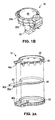
- Figs. 2A-2C illustrate the cassette assembly 12, which includes a housing 46 having upper and lower cassette housing portions 46a/46b respectively, that snap together via engagement tabs 48 that extend from the upper cassette housing 46a and engage with lower cassette housing 46b.
- Lower cassette housing 46b includes an annular sidewall 50 with a shoulder 52 extending from an inner surface of the sidewall 50.
- Upper cassette housing 46a includes an annular sidewall 54. When upper/lower cassette housings 46a/46b are snapped together, upper cassette sidewall 54 fits inside lower cassette sidewall 50, where sidewall 54 and the shoulder portion of sidewall 50 together define an inwardly facing annular compression surface 56.
- Upper cassette sidewall 54 is positioned a fixed distance away from shoulder 52 to define a channel 58 in the annular compression surface 56.
- a hollow compression tube 60 is removably disposed along the compression surface 56.
- the compression tube 60 includes a flange 62 adhered thereto or integrally formed therewith.
- the flange 62 snuggly inserts into channel 58 with a friction fit that evenly secures compression tube 60 against compression surface 56.
- flange 62 is a solid tube-shaped member that is integrally formed as part of the compression tube 60, and that has a thickness corresponding to the width of channel 58.
- the compression tube 60 has an input end 60a and an output end 60b.
- upper and lower cassette housings 46a/46b are snapped together, with a compression tube 60 secured against compression surface 56 via flange 62 (held in channel 58).
- the upper pump housing 20a is rotated open (away from lower pump housing 20b), and the cassette assembly 14 is inserted in lower pump housing 20b.
- the upper pump housing 20a is then closed, securely holding cassette assembly 12 in cavity 26.
- roller arm 28 rotates within the cavity 26, so that roller 29 engages with compression tube 60 and compresses it against compression surface 56.
- the spring loaded roller arm 28 ensures that roller 29 is compressed against compression tube 60 with the desired amount of force, so that roller 29 creates an occlusion in the compression tube 60 which moves along the length of tube 60 as roller arm 28 makes a single revolution within cavity 26.
- the moving tube occlusion pushes a known quantity of fluid through the compression tube 60 in a uniform manner.
- the roller 29 has moved along the entire length of the compression tube portion that is disposed on compression surface 56, and has disengaged from compression tube 60.
- the pump shown in the figures occludes the compression tube during (or for) 285 degrees of the rotation of roller arm 28, leaving 75 degrees of rotation where the roller 29 does not compress tube 60.
- the diameter of the compression tube 60 is selected so that the desired amount of fluid for a single process step (e.g. collection of images via a flow cell) can be produced by a single revolution of the roller arm 28, thus avoiding any pulsations caused by the repeated engagement and disengagement of the roller 29 with compression tube 60.
- a single process step e.g. collection of images via a flow cell
- tube squirm and fluid flow variations caused therefrom are avoided.
- a uniform delivery of fluid volume results from each incremental degree of rotation of roller arm 28.
- the roller 29 is preferably parked in a default or rest position shown in Fig.
- roller 29 does not contact the compression tube 60, thus preventing premature tube failure due to the formation of flat spots therein.
- roller 29 can be temporarily parked on compression tube 60 so that the (stalled) tube occlusion acts as a temporary pinch-valve for the fluid inside compression tube 60.
- the removable cassette 12 allows for easy replacement of the compression tubing 60 by the user. Insertion of the flange 62 into channel 58 is convenient and provides a repeatable positioning of the tubing 60 against compression surface 56.
- the tubing 60, and/or the cassette assembly 12 in its entirety, can be replaced by the user as tube 60 ages, ideally without the use of any tools.
- Closing upper housing 20a onto lower housing 20b compresses the cassette assembly 12 to secure compression tubing 60 and compression surface 56 in place (relative to pump assembly 10 and in particular roller 29).
- the clamping features of both the cassette assembly 12 and pump assembly 10 provide repeatable and convenient assembly and performance of the pump.
- the pump preferably uses tubing 60 having a symmetrical cross-section, which permits more uniform fabrication of the tubing and more repeatable pump performance, and is ideal for clamping features of the cassette assembly 12.
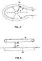
- the amount of longitudinal travel of the rotating arm could be more limited, where the roller 29 ceases compression of, and even possibly loses contact with, the compression tube at multiple points through its revolution, as illustrated in Fig. 4 .
- the roller 29 twice loses contact with the compression tube 60, so that the pump produces two separate pulses of fluid flow per full revolution of the arm 28.
- roller 29 need not rotate about a fixed point, but can include translational movement, as shown in Fig. 5 .
- spring loaded arm 28 is connected to a moving conveyor belt or track 64 that moves roller 29 along a planar compression surface 56.
- One or more additional roller arms 28 can be added to belt/track 64, so long as only one roller is engaged with compression tube 60 at any given time.
Description
- The present invention relates to a pump of the kind comprising a pump housing that defines a cavity, the pump housing including a first pump housing portion and a second pump housing portion, the pump housing portions being engageable with one another to close the pump housing and being separable from one another to open the pump housing, a compression surface within the cavity and having a channel formed therein, a hollow compression tube secured to the compression surface, the hollow compression tube including a flange extending along a length thereof, and the flange being removably engaged with the channel for securing the compression tube to the compression surface, compression means within the cavity for incrementally compressing the compression tube against the compression surface to create a moving occlusion of the compression tube that uniformly pushes fluid through the compression tube, wherein the compression means has at least one rest position in which the compression means does not compress the compression tube, the compression means including a roller and means for moving the roller relative to the pump housing when the pump housing is closed, and a motor disposed outside the cavity and drivingly engaged with the moving means.
- Methods and systems for analyzing particles and particularly sediments are well known in the art, as disclosed in
U. S. Patents 4,338, 024 and4,393, 466 . Such systems utilize a flow cell though which fluid samples are passed, and a particle analyzer for capturing still frame images of the fluid passing through the flow cell. Thus, the flow cell positions and presents the sample fluid containing particles of interest for analysis. The more accurately that the sample fluid is positioned by the flow cell, the better the analysis of the particles therein that can be made. - Typical flow cells cause the sample fluid, and a sheath fluid that buffers the sample fluid, to flow together from a large entry chamber into a small cross sectional examination area or region. The transition from the inlet or entry chambers to the examination legion forms a hydrodynamic lens that squeezes both the sample fluid and the sheath fluid proportionally into the smaller space. Where the particles of interest are microscopic particles, the resulting cross-sectional space occupied by the sample fluid must be positioned within the depth of field of the analyzer, such as an optical system or a laser system, to obtain the best analytical information. For the best hydrodynamic focus, a large area of sheath flow must envelop the small area of sample fluid without any swirling or vortices. Thus, uniform flow of sample and sheath fluids through the flow cell is essential for optimal operation of particle analyzers.
- Displacement pumps, (e.g. tubing or peristaltic pumps), are well known in the art and have been used to pump fluid samples and sheath fluids through flow cells. Conventional peristaltic pumps include multiple rollers that roll along flexible tubing containing fluid. The rollers push the fluid along the length of the tubing, drawing fluid into an input end of the tubing and forcing fluid out an output end of the tubing. A common configuration includes a rotating hub with rollers on its periphery, and an annularly shaped housing against which the tubing is pressed. With each rotation of the hub, each roller engages with, rolls along the length of, and disengages from, the tubing. At least one of the rollers is in contact with the tubing at all times so that fluid cannot flow backwards through the tubing.
- Conventional peristaltic pumps have several drawbacks. For example, multiple rollers engaging with and disengaging from the flexible tube cause pulsations in the fluid flow through the pump, which can be problematic for proper operation of flow cells. Moreover, the amount of fluid delivered by the pump for n degrees of rotation is dependent on the starting angle of the rollers. Most pump designs only retain the tube at its ends, relying on the multiple rollers engaged with tubing to hold it in its circular path along the housing. Thus, the tube can stretch and contract as the rollers move across its length, which again can cause varying flow and uncertainty in the volume moved by rollers. Lastly, when the pump is shut down, rollers are left in contact with the tube, causing compression setting (flat spotting) of the tube, which adversely affects the uniform flow of the fluid after the pump is activated again.
- There is a need for a displacement pump that provides uniform fluid flow of known and repeatable quantities, and which does not produce flat spots on the tube during non use.
-
US 2,693,766 which is considered to be the closest prior art, describes a pump of the kind defined hereinbefore at the beginning in which the compression surface is an internal surface of the pump housing. The compressing means consists of a set of three equiangularly arranged rollers, which may be spring loaded. This roller arrangement is mounted to an axle extending rotatably through the pump housing and having a pulley fixed to its end outside the pump housing. The axle can be moved to bring the roller arrangement into a position in which none of the rollers compresses the tube. Claim 1 is limited in the two-part form over the disclosure of this document. - According to the present invention a pump of the kind defined hereinbefore is characterised by a cassette housing disposed in the cavity and containing the hollow compression tube, the cassette housing being shaped to define the compression surface and the said channel and to be removable together with the hollow compression tube from the cavity when the pump housing is open while leaving the moving means and the roller remaining in the cavity, and in that the cassette housing has a lower cassette housing portion and an upper cassette housing portion removably attached to the lower cassette portion whereby the hollow compression tube can be secured to and released from the cassette housing.
- The invention will now be described by way of example with reference to the accompanying drawings, in which:
-
Fig. 1A is an exploded view of a pump embodying the present invention. -
Fig. 1B is a perspective view of the pump assembly ofFig 1A . -
Fig. 2A is an exploded view of the cassette assembly of the pump ofFigs 1A andB. -
Fig. 2B is a perspective view of the cassette housing (without compression tube) of the cassette assembly ofFig 2A . -
Fig. 2C is a perspective view of the cassette assembly ofFigs 2A . -
Fig. 3 is a top view of an alternative embodiment of the present invention. -
Fig. 4 is a top view of a second alternative embodiment of the present invention. -
Fig. 5 is a side view of a third alternative embodiment of the present invention. - A uniform displacement pump embodying the present invention is illustrated in
Figs. 1A- 1B and2A-2C , and includes apump assembly 10 and acassette assembly 12.Figs. 1A-1B illustrate thepump assembly 10, which includes a housing 20 having upper andlower housing portions 20a/20b respectively, that are hingedly attached to each other by ahinge 22 andhinge bracket 24. Whenupper housing 20a is closed overlower housing 20b, anannular cavity 26 is defined thereby. Aroller arm 28, which is preferably spring loaded, is disposed in thecavity 26.Roller arm 28 has a proximal end at the center of thecavity 26, and a distal end with an outwardly facingcompression roller 29 mounted thereon. Amotor 30 has adrive shaft 32 that extends into thecavity 26 and is attached to the proximal end of theroller arm 28, for rotating theroller 29 around the periphery of thecavity 26. Asensor assembly 34 is mounted to thelower housing 20b and includes asensor switch 36 for detecting aclosure pin 38 from theupper housing 20a, indicating that theupper housing 20a is in a closed position overlower housing 20b.Sensor assembly 34 also includes asensor switch 37 that detects the presence of thecassette assembly 12 incavity 26, and asensor 40 that detects and verifies the position of theroller arm 28. -
Figs. 2A-2C illustrate thecassette assembly 12, which includes a housing 46 having upper and lowercassette housing portions 46a/46b respectively, that snap together viaengagement tabs 48 that extend from theupper cassette housing 46a and engage withlower cassette housing 46b.Lower cassette housing 46b includes anannular sidewall 50 with ashoulder 52 extending from an inner surface of thesidewall 50.Upper cassette housing 46a includes anannular sidewall 54. When upper/lower cassette housings 46a/46b are snapped together,upper cassette sidewall 54 fits insidelower cassette sidewall 50, wheresidewall 54 and the shoulder portion ofsidewall 50 together define an inwardly facingannular compression surface 56.Upper cassette sidewall 54 is positioned a fixed distance away fromshoulder 52 to define achannel 58 in theannular compression surface 56. - A
hollow compression tube 60 is removably disposed along thecompression surface 56. Thecompression tube 60 includes aflange 62 adhered thereto or integrally formed therewith. Theflange 62 snuggly inserts intochannel 58 with a friction fit that evenly securescompression tube 60 againstcompression surface 56. Preferably,flange 62 is a solid tube-shaped member that is integrally formed as part of thecompression tube 60, and that has a thickness corresponding to the width ofchannel 58. Thecompression tube 60 has aninput end 60a and anoutput end 60b. - To assemble pump 1, upper and
lower cassette housings 46a/46b are snapped together, with acompression tube 60 secured againstcompression surface 56 via flange 62 (held in channel 58). Theupper pump housing 20a is rotated open (away fromlower pump housing 20b), and the cassette assembly 14 is inserted inlower pump housing 20b. Theupper pump housing 20a is then closed, securely holdingcassette assembly 12 incavity 26. - When
motor 30 is activated,roller arm 28 rotates within thecavity 26, so thatroller 29 engages withcompression tube 60 and compresses it againstcompression surface 56. The spring loadedroller arm 28 ensures thatroller 29 is compressed againstcompression tube 60 with the desired amount of force, so thatroller 29 creates an occlusion in thecompression tube 60 which moves along the length oftube 60 asroller arm 28 makes a single revolution withincavity 26. The moving tube occlusion pushes a known quantity of fluid through thecompression tube 60 in a uniform manner. By the time theroller arm 28 completes its single revolution, theroller 29 has moved along the entire length of the compression tube portion that is disposed oncompression surface 56, and has disengaged fromcompression tube 60. The pump shown in the figures occludes the compression tube during (or for) 285 degrees of the rotation ofroller arm 28, leaving 75 degrees of rotation where theroller 29 does not compresstube 60. - Ideally, the diameter of the
compression tube 60 is selected so that the desired amount of fluid for a single process step (e.g. collection of images via a flow cell) can be produced by a single revolution of theroller arm 28, thus avoiding any pulsations caused by the repeated engagement and disengagement of theroller 29 withcompression tube 60. By continuously anchoring thecompression tube 60 against the compression surface (i.e. using thecontinuous flange 62 engaged in the continuous channel 58), tube squirm and fluid flow variations caused therefrom are avoided. A uniform delivery of fluid volume results from each incremental degree of rotation ofroller arm 28. When the pump is inactive, theroller 29 is preferably parked in a default or rest position shown inFig. 1A , where theroller 29 does not contact thecompression tube 60, thus preventing premature tube failure due to the formation of flat spots therein. However,roller 29 can be temporarily parked oncompression tube 60 so that the (stalled) tube occlusion acts as a temporary pinch-valve for the fluid insidecompression tube 60. - The
removable cassette 12 allows for easy replacement of thecompression tubing 60 by the user. Insertion of theflange 62 intochannel 58 is convenient and provides a repeatable positioning of thetubing 60 againstcompression surface 56. Thetubing 60, and/or thecassette assembly 12 in its entirety, can be replaced by the user astube 60 ages, ideally without the use of any tools. Closingupper housing 20a ontolower housing 20b compresses thecassette assembly 12 to securecompression tubing 60 andcompression surface 56 in place (relative to pumpassembly 10 and in particular roller 29). The clamping features of both thecassette assembly 12 and pumpassembly 10 provide repeatable and convenient assembly and performance of the pump. The pump preferably usestubing 60 having a symmetrical cross-section, which permits more uniform fabrication of the tubing and more repeatable pump performance, and is ideal for clamping features of thecassette assembly 12. - It is to be understood that the present invention is not limited to the embodiment(s) described above and illustrated herein, but encompasses any and all variations falling within the scope of the appended claims. For example, while
pump housing portions 20a/20b are shown hingedly attached, they could instead snap together in the manner shown forcassette housing portions 46a/46b, and vice versa.Arm 28 need not necessarily be spring loaded.Compression surface 56 need not be circular, so long as the spring loadedroller arm 28 can maintain a desired minimal force for compressingcompression tube 60. For example, the compression surface could be elliptical, where the rotating spring loaded roller arm has enough longitudinal travel (along the length of arm 28) to maintain contact with thecompression tube 60 with sufficient force during the arm's revolution, as illustrated inFig. 3 . Alternately, the amount of longitudinal travel of the rotating arm could be more limited, where theroller 29 ceases compression of, and even possibly loses contact with, the compression tube at multiple points through its revolution, as illustrated inFig. 4 . In this case, theroller 29 twice loses contact with thecompression tube 60, so that the pump produces two separate pulses of fluid flow per full revolution of thearm 28. In fact,roller 29 need not rotate about a fixed point, but can include translational movement, as shown inFig. 5 . In this embodiment, spring loadedarm 28 is connected to a moving conveyor belt or track 64 that movesroller 29 along aplanar compression surface 56. One or more additional roller arms 28 (with rollers 29) can be added to belt/track 64, so long as only one roller is engaged withcompression tube 60 at any given time.
Claims (16)
- A pump, comprising:a pump housing (20a, 20b) that defines a cavity (26), the pump housing including a first pump housing portion (20b) and a second pump housing portion (20a), the pump housing portions (20a,20b) being engageable with one another to close the pump housing and being separable from one another to open the pump housing:a compression surface (56) within the cavity (26) and having a channel (58) formed therein;a hollow compression tube (60) secured to the compression surface (56), the hollow compression tube including a flange (62) extending along a length thereof, and the flange (62) being removably engaged with the channel (58) for securing the compression tube to the compression surface;compression means (28, 29) within the cavity (26) for incrementally compressing the compression tube (60) against the compression surface (56) to create a moving occlusion of the compression tube that uniformly pushes fluid through the compression tube, wherein the compression means (28, 29) has at least one rest position in which the compression means does not compress the compression tube, the compression means including a roller (29) and means (28) for moving the roller (29) relative to the pump housing (20a, 20b) when the pump housing is closed; anda motor (30) disposed outside the cavity (26) and drivingly engaged with the moving means (28), characterised bya cassette housing (46a, 46b) disposed in the cavity (26) and containing the hollow compression tube (60), the cassette housing being shaped to define the compression surface (56) and the said channel (58) and to be removable together with the hollow compression tube (60) from the cavity (26) when the pump housing (20a, 20b) is open while leaving the moving means (28) and the roller (29) remaining in the cavity (26), and in that the cassette housing has a lower cassette housing portion (46b) and an upper cassette housing portion (46a) removably attached to the lower cassette portion (46b) whereby the hollow compression tube (60) can be secured to and released from the cassette housing.
- The pump of claim 1, wherein the compression surface (56) is annularly shaped, and the moving means comprises a spring loaded arm (28) that rotates about a fixed point.
- The pump of claim 1, wherein the compression surface (56) is elliptically shaped; and the moving means comprises a spring loaded arm (28) that rotates about a fixed point.
- The pump of claim 3, wherein as the spring loaded arm (28) rotates through a complete revolution about the fixed point, the roller (29) disengages from the compression tube (60) at least twice.
- The pump of claim 1, wherein the compression means has a plurality of rollers that roll along the compression tube, and no more than one of the plurality of rollers compresses the compression tube at any given time.
- The pump of claim 1, wherein the flange (58) is tube shaped and integrally formed with the compression tube (60).
- The pump of claim 1, wherein the compression means includes a second rest position in which the compression means forms a temporary pinch-valve by temporarily stalling the moving occlusion of the compression tube.
- The pump of claim 1, wherein the moving means includes an arm (28) having a proximal end and a distal end, wherein the roller (29) is attached to the distal end of the arm (28) and the motor (30) is drivingly engageable with the proximal end of the arm (28).
- The pump of claim 8, wherein the arm (28) is spring loaded for applying pressure on the compression tube (60) by the roller (29).
- The pump of claim 8, wherein the arm (28) has a rest rotational position where the roller does not contact the compression tube.
- The pump of claim 10, wherein the second pump housing portion (20a) is hingedly attached to the first pump housing portion (20b).
- The pump of claim 10, further comprising a sensor (36) for sensing that the second pump housing portion (20a) is positioned in a closed position relative to the first pump housing portion (20b).
- The pump of claim 1, further comprising a sensor (37) for sensing that the cassette housing (12) is disposed in the cavity (26).
- The pump of claim 1, wherein the lower cassette housing portion (46b) includes an annular sidewall (50) and a shoulder (52) extending from the annular sidewall, the upper cassette housing portion (46a) includes an annular sidewall (54), and the annular sidewalls (50, 54) of the lower and upper cassette housing portions mate together to form the compression surface (56), where the upper cassette housing portion sidewall (54) is positioned a fixed distance away from the shoulder (53) to define the channel (58).
- The pump of claim 1, wherein one of the lower and upper cassette housing portions includes tabs (48) for engaging the other of the lower and upper cassette housing portions.
- The pump of claim 10, wherein the arm (28) has a second rest rotational position where the roller (29) forms a temporary pinch-valve by temporarily stalling the moving occlusion of the compression tube (60).
Applications Claiming Priority (3)
| Application Number | Priority Date | Filing Date | Title |
|---|---|---|---|
| US42746802P | 2002-11-18 | 2002-11-18 | |
| US427468P | 2002-11-18 | ||
| PCT/US2003/036831 WO2004046553A2 (en) | 2002-11-18 | 2003-11-17 | Uniform flow displacement pump |
Publications (3)
| Publication Number | Publication Date |
|---|---|
| EP1579115A2 EP1579115A2 (en) | 2005-09-28 |
| EP1579115A4 EP1579115A4 (en) | 2011-01-26 |
| EP1579115B1 true EP1579115B1 (en) | 2013-05-15 |
Family
ID=32326540
Family Applications (1)
| Application Number | Title | Priority Date | Filing Date |
|---|---|---|---|
| EP03786805.6A Expired - Lifetime EP1579115B1 (en) | 2002-11-18 | 2003-11-17 | Uniform flow displacement pump |
Country Status (9)
| Country | Link |
|---|---|
| US (3) | US7150607B2 (en) |
| EP (1) | EP1579115B1 (en) |
| JP (1) | JP4221375B2 (en) |
| CN (1) | CN100476207C (en) |
| AU (1) | AU2003295607B2 (en) |
| CA (1) | CA2505720C (en) |
| DK (1) | DK1579115T3 (en) |
| ES (1) | ES2421086T3 (en) |
| WO (1) | WO2004046553A2 (en) |
Families Citing this family (21)
| Publication number | Priority date | Publication date | Assignee | Title |
|---|---|---|---|---|
| AU2003253592A1 (en) * | 2002-02-25 | 2003-09-29 | Jiri Vanek | Peristaltic rotation pump with exact, especially mechanically linear dosage |
| EP1565795B1 (en) * | 2002-11-18 | 2008-11-12 | International Remote Imaging Systems, Inc. | A multi-level controller system |
| US7556481B2 (en) * | 2005-08-26 | 2009-07-07 | Baxter International Inc. | Rotary axial peristaltic pumps and related methods |
| IN2009KO01235A (en) * | 2008-10-20 | 2015-08-14 | Fmo Technology Gmbh | |
| CN101749219B (en) * | 2008-12-11 | 2012-06-20 | 清华大学 | Miniature peristaltic pump |
| AU2010245166B2 (en) | 2009-05-06 | 2014-04-17 | Alcon Inc. | Multiple segmented peristaltic pump and cassette |
| DE102009029305A1 (en) | 2009-09-09 | 2011-03-10 | Endress + Hauser Conducta Gesellschaft für Mess- und Regeltechnik mbH + Co. KG | Analyzer for the automated determination of a measured variable of a liquid sample |
| US20110137231A1 (en) | 2009-12-08 | 2011-06-09 | Alcon Research, Ltd. | Phacoemulsification Hand Piece With Integrated Aspiration Pump |
| CN101776064A (en) * | 2010-03-02 | 2010-07-14 | 储江波 | Sanitary hose pump |
| CN102155399A (en) * | 2011-03-18 | 2011-08-17 | 无锡市华茂电器研究所 | Pipe jacket for peristaltic pump |
| US9334876B2 (en) | 2011-04-12 | 2016-05-10 | Thermo Neslab Inc. | Pump casing and related apparatus and methods |
| US9445943B2 (en) | 2012-12-11 | 2016-09-20 | Alcon Research, Ltd. | Phacoemulsification hand piece with integrated aspiration and irrigation pump |
| US9962288B2 (en) | 2013-03-07 | 2018-05-08 | Novartis Ag | Active acoustic streaming in hand piece for occlusion surge mitigation |
| US9545337B2 (en) | 2013-03-15 | 2017-01-17 | Novartis Ag | Acoustic streaming glaucoma drainage device |
| US9693896B2 (en) | 2013-03-15 | 2017-07-04 | Novartis Ag | Systems and methods for ocular surgery |
| US9915274B2 (en) | 2013-03-15 | 2018-03-13 | Novartis Ag | Acoustic pumps and systems |
| US9750638B2 (en) | 2013-03-15 | 2017-09-05 | Novartis Ag | Systems and methods for ocular surgery |
| US9126219B2 (en) | 2013-03-15 | 2015-09-08 | Alcon Research, Ltd. | Acoustic streaming fluid ejector |
| CN105179213A (en) * | 2015-10-09 | 2015-12-23 | 冯筠荪 | End face peristaltic pump |
| CN109649011A (en) * | 2019-01-08 | 2019-04-19 | 北京印刷学院 | A kind of machinery head out of ink |
| US11638780B1 (en) * | 2022-03-29 | 2023-05-02 | Robert Howard | Medical drainage pump |
Citations (1)
| Publication number | Priority date | Publication date | Assignee | Title |
|---|---|---|---|---|
| GB2012373A (en) * | 1978-01-11 | 1979-07-25 | Medical Sciences Int | Peristaltic infusion pump and disposable casette for use therewith |
Family Cites Families (35)
| Publication number | Priority date | Publication date | Assignee | Title |
|---|---|---|---|---|
| US3192863A (en) * | 1962-03-14 | 1965-07-06 | Grenobloise Etude Appl | Blood pump |
| US2899906A (en) * | 1959-08-18 | Roller pumps | ||
| US1338024A (en) * | 1915-05-10 | 1920-04-27 | George E Lee Company | Thermostat |
| GB676349A (en) * | 1949-12-13 | 1952-07-23 | Louis Antoine Seyler | Improvements in or relating to rotary pumps of the resilient tube type |
| US2693765A (en) * | 1951-09-22 | 1954-11-09 | American Optical Corp | Fluid pump and method of making the same |
| US2987004A (en) * | 1955-07-29 | 1961-06-06 | Jerome L Murray | Fluid pressure device |
| US2977890A (en) | 1956-02-10 | 1961-04-04 | Seyler Leon Antoine | Pumps and compressors of the flexible-tube type |
| US3565554A (en) * | 1969-08-26 | 1971-02-23 | Us Catheter & Instr Corp | Reinforced compressible fluid transporting tube |
| US3606596A (en) * | 1970-04-14 | 1971-09-20 | Miles Lowell Edwards | Drug dispensing pump |
| FR2102904A5 (en) | 1970-08-28 | 1972-04-07 | Logeais Labor Jacques | |
| US3930761A (en) * | 1972-12-19 | 1976-01-06 | The Boots Company, Ltd. | Portable and manually operable peristaltic pump |
| FR2317526A1 (en) * | 1975-07-08 | 1977-02-04 | Rhone Poulenc Ind | PERISTALTIC PUMP |
| GB1578022A (en) * | 1976-05-05 | 1980-10-29 | Iles F | Peristaltic pumps |
| US4338024A (en) | 1980-05-02 | 1982-07-06 | International Remote Imaging Systems, Inc. | Flow analyzer and system for analysis of fluids with particles |
| GB2076476A (en) | 1980-05-08 | 1981-12-02 | Warner Lambert Uk Ltd | Peristaltic fluid-machines |
| JPS5724482A (en) | 1980-07-21 | 1982-02-09 | Citizen Watch Co Ltd | Delivery device for fluid |
| US4393466A (en) | 1980-09-12 | 1983-07-12 | International Remote Imaging Systems | Method of analyzing particles in a dilute fluid sample |
| US4333088A (en) * | 1980-11-03 | 1982-06-01 | Exxon Research & Engineering Co. | Disposable peristaltic pump assembly for facsimile printer |
| CN86200414U (en) * | 1986-01-19 | 1986-11-05 | 青岛全密封耐蚀泵开发公司 | Full-seal corrosion resisting pump |
| CA1296591C (en) * | 1986-12-03 | 1992-03-03 | Meddiss, Inc. | Pulsatile flow delivery apparatus |
| CN87101956A (en) * | 1987-03-12 | 1988-09-21 | 王芷龙 | Pipe deforming pump |
| CN2033067U (en) * | 1988-08-04 | 1989-02-22 | 黄明 | Ellipse rotor self-suck pump |
| US4936760A (en) * | 1989-06-12 | 1990-06-26 | Williams David R | Volumetric infusion pump |
| CN2055874U (en) * | 1989-08-24 | 1990-04-11 | 吉林市火炬红外线汽化油炉厂 | Miniature water pump without water seal |
| US5062775A (en) * | 1989-09-29 | 1991-11-05 | Rocky Mountain Research, Inc. | Roller pump in an extra corporeal support system |
| EP0544478B1 (en) * | 1991-11-25 | 1996-10-09 | Unilever Plc | Fatty acid esters of alkoxylated isethionic acid and detergent compositions comprising the same |
| US5620312A (en) * | 1995-03-06 | 1997-04-15 | Sabratek Corporation | Infusion pump with dual-latching mechanism |
| JP3186577B2 (en) * | 1996-03-27 | 2001-07-11 | 三浦工業株式会社 | Liquid ejection device |
| US6184978B1 (en) | 1996-05-15 | 2001-02-06 | International Remote Imaging Systems, Inc. | Method and apparatus for verifying uniform flow of a fluid sample through a flow cell and distribution on a slide |
| JP3587226B2 (en) * | 1996-07-11 | 2004-11-10 | セイコーエプソン株式会社 | Ink jet recording device and pump used for the same |
| FR2753236B1 (en) * | 1996-09-10 | 1998-12-04 | Conseilray Sa | MINIATURE PERISTALTIC PUMP |
| CN2344585Y (en) * | 1997-07-11 | 1999-10-20 | 马连发 | Hose pump |
| US6473172B1 (en) | 2000-09-20 | 2002-10-29 | International Remote Imaging Systems, Inc. | Flow cell and method of operating therefor |
| US6494693B1 (en) * | 2000-10-23 | 2002-12-17 | Cole-Parmer Instrument Company | Peristatic pump |
| JP4557452B2 (en) | 2001-03-13 | 2010-10-06 | 日本電産サーボ株式会社 | Roller pump |
-
2003
- 2003-10-29 US US10/696,804 patent/US7150607B2/en not_active Expired - Fee Related
- 2003-11-17 DK DK03786805.6T patent/DK1579115T3/en active
- 2003-11-17 CA CA002505720A patent/CA2505720C/en not_active Expired - Fee Related
- 2003-11-17 WO PCT/US2003/036831 patent/WO2004046553A2/en active IP Right Grant
- 2003-11-17 JP JP2004553879A patent/JP4221375B2/en not_active Expired - Fee Related
- 2003-11-17 ES ES03786805T patent/ES2421086T3/en not_active Expired - Lifetime
- 2003-11-17 CN CNB2003801035116A patent/CN100476207C/en not_active Expired - Fee Related
- 2003-11-17 EP EP03786805.6A patent/EP1579115B1/en not_active Expired - Lifetime
- 2003-11-17 AU AU2003295607A patent/AU2003295607B2/en not_active Ceased
-
2006
- 2006-12-05 US US11/634,672 patent/US20070077158A1/en not_active Abandoned
-
2013
- 2013-05-06 US US13/887,490 patent/US20130243631A1/en not_active Abandoned
Patent Citations (1)
| Publication number | Priority date | Publication date | Assignee | Title |
|---|---|---|---|---|
| GB2012373A (en) * | 1978-01-11 | 1979-07-25 | Medical Sciences Int | Peristaltic infusion pump and disposable casette for use therewith |
Also Published As
| Publication number | Publication date |
|---|---|
| EP1579115A2 (en) | 2005-09-28 |
| US20070077158A1 (en) | 2007-04-05 |
| AU2003295607A1 (en) | 2004-06-15 |
| CA2505720A1 (en) | 2004-06-03 |
| US20130243631A1 (en) | 2013-09-19 |
| JP2006506579A (en) | 2006-02-23 |
| WO2004046553A2 (en) | 2004-06-03 |
| CA2505720C (en) | 2009-11-10 |
| AU2003295607B2 (en) | 2007-06-07 |
| US7150607B2 (en) | 2006-12-19 |
| JP4221375B2 (en) | 2009-02-12 |
| ES2421086T3 (en) | 2013-08-28 |
| CN100476207C (en) | 2009-04-08 |
| CN1711420A (en) | 2005-12-21 |
| WO2004046553A3 (en) | 2005-07-28 |
| EP1579115A4 (en) | 2011-01-26 |
| US20040096347A1 (en) | 2004-05-20 |
| DK1579115T3 (en) | 2013-08-19 |
Similar Documents
| Publication | Publication Date | Title |
|---|---|---|
| US20130243631A1 (en) | Uniform flow displacement pump | |
| AU2003291562C1 (en) | Flow cell for urinalysis diagnostic system and method of making same | |
| JP4235501B2 (en) | Peristaltic hose pump | |
| KR101862540B1 (en) | Pump module, base pump module and pump system | |
| JP4511388B2 (en) | Capacity infusion pump | |
| US20090269248A1 (en) | Method and apparatus for analyte processing | |
| MX2008002725A (en) | Rotary axial peristaltic pumps and related methods. | |
| JP4838237B2 (en) | Peristaltic pump system | |
| CA2778134C (en) | Peristaltic pump and hose cartridge therefor | |
| US11338288B2 (en) | Peristaltic pump and analyzer for testing a sample | |
| EP3523031B1 (en) | Analysis device, cartridge and method for testing a sample | |
| MX2008008990A (en) | Peristaltic pump including an elastically displaceable locking plate |
Legal Events
| Date | Code | Title | Description |
|---|---|---|---|
| PUAI | Public reference made under article 153(3) epc to a published international application that has entered the european phase |
Free format text: ORIGINAL CODE: 0009012 |
|
| 17P | Request for examination filed |
Effective date: 20050617 |
|
| AK | Designated contracting states |
Kind code of ref document: A2 Designated state(s): AT BE BG CH CY CZ DE DK EE ES FI FR GB GR HU IE IT LI LU MC NL PT RO SE SI SK TR |
|
| AX | Request for extension of the european patent |
Extension state: AL LT LV MK |
|
| RIN1 | Information on inventor provided before grant (corrected) |
Inventor name: PELMULDER, JOHN, P. Inventor name: DIAZ, CONRADO, O. |
|
| A4 | Supplementary search report drawn up and despatched |
Effective date: 20101227 |
|
| 17Q | First examination report despatched |
Effective date: 20110413 |
|
| GRAP | Despatch of communication of intention to grant a patent |
Free format text: ORIGINAL CODE: EPIDOSNIGR1 |
|
| GRAC | Information related to communication of intention to grant a patent modified |
Free format text: ORIGINAL CODE: EPIDOSCIGR1 |
|
| GRAJ | Information related to disapproval of communication of intention to grant by the applicant or resumption of examination proceedings by the epo deleted |
Free format text: ORIGINAL CODE: EPIDOSDIGR1 |
|
| GRAP | Despatch of communication of intention to grant a patent |
Free format text: ORIGINAL CODE: EPIDOSNIGR1 |
|
| GRAS | Grant fee paid |
Free format text: ORIGINAL CODE: EPIDOSNIGR3 |
|
| GRAA | (expected) grant |
Free format text: ORIGINAL CODE: 0009210 |
|
| AK | Designated contracting states |
Kind code of ref document: B1 Designated state(s): AT BE BG CH CY CZ DE DK EE ES FI FR GB GR HU IE IT LI LU MC NL PT RO SE SI SK TR |
|
| AX | Request for extension of the european patent |
Extension state: AL LT LV MK |
|
| REG | Reference to a national code |
Ref country code: GB Ref legal event code: FG4D Ref country code: CH Ref legal event code: EP |
|
| REG | Reference to a national code |
Ref country code: AT Ref legal event code: REF Ref document number: 612298 Country of ref document: AT Kind code of ref document: T Effective date: 20130615 |
|
| REG | Reference to a national code |
Ref country code: IE Ref legal event code: FG4D |
|
| REG | Reference to a national code |
Ref country code: DE Ref legal event code: R096 Ref document number: 60344074 Country of ref document: DE Effective date: 20130711 |
|
| REG | Reference to a national code |
Ref country code: DE Ref legal event code: R082 Ref document number: 60344074 Country of ref document: DE Representative=s name: 2K PATENTANWAELTE BLASBERG KEWITZ & REICHEL, P, DE |
|
| REG | Reference to a national code |
Ref country code: CH Ref legal event code: NV Representative=s name: ING. MARCO ZARDI C/O M. ZARDI AND CO. S.A., CH Ref country code: CH Ref legal event code: PFA Owner name: IRIS INTERNATIONAL, INC., US Free format text: FORMER OWNER: INTERNATIONAL REMOTE IMAGING SYSTEMS, INC., US |
|
| REG | Reference to a national code |
Ref country code: DK Ref legal event code: T3 |
|
| RAP2 | Party data changed (patent owner data changed or rights of a patent transferred) |
Owner name: IRIS INTERNATIONAL, INC. |
|
| REG | Reference to a national code |
Ref country code: NL Ref legal event code: T3 |
|
| REG | Reference to a national code |
Ref country code: ES Ref legal event code: FG2A Ref document number: 2421086 Country of ref document: ES Kind code of ref document: T3 Effective date: 20130828 Ref country code: NL Ref legal event code: TD Effective date: 20130820 |
|
| REG | Reference to a national code |
Ref country code: DE Ref legal event code: R081 Ref document number: 60344074 Country of ref document: DE Owner name: IRIS INTERNATIONAL, INC., US Free format text: FORMER OWNER: INTERNATIONAL REMOTE IMAGING SYSTEMS INC., CHATSWORTH, US Effective date: 20130516 Ref country code: DE Ref legal event code: R081 Ref document number: 60344074 Country of ref document: DE Owner name: IRIS INTERNATIONAL, INC., US Free format text: FORMER OWNER: INTERNATIONAL REMOTE IMAGING SYSTEMS INC., CHATSWORTH, US Effective date: 20130807 Ref country code: DE Ref legal event code: R082 Ref document number: 60344074 Country of ref document: DE Representative=s name: 2K PATENTANWAELTE BLASBERG KEWITZ & REICHEL, P, DE Effective date: 20130807 Ref country code: DE Ref legal event code: R081 Ref document number: 60344074 Country of ref document: DE Owner name: IRIS INTERNATIONAL, INC., CHATSWORTH, US Free format text: FORMER OWNER: INTERNATIONAL REMOTE IMAGING SYSTEMS INC., CHATSWORTH, CALIF., US Effective date: 20130516 Ref country code: DE Ref legal event code: R082 Ref document number: 60344074 Country of ref document: DE Representative=s name: 2K PATENTANWAELTE BLASBERG KEWITZ & REICHEL PA, DE Effective date: 20130807 Ref country code: DE Ref legal event code: R081 Ref document number: 60344074 Country of ref document: DE Owner name: IRIS INTERNATIONAL, INC., CHATSWORTH, US Free format text: FORMER OWNER: INTERNATIONAL REMOTE IMAGING SYSTEMS INC., CHATSWORTH, CALIF., US Effective date: 20130807 |
|
| REG | Reference to a national code |
Ref country code: AT Ref legal event code: HC Ref document number: 612298 Country of ref document: AT Kind code of ref document: T Owner name: IRIS INTERNATIONAL, INC., US Effective date: 20130905 |
|
| REG | Reference to a national code |
Ref country code: LT Ref legal event code: MG9D |
|
| PG25 | Lapsed in a contracting state [announced via postgrant information from national office to epo] |
Ref country code: SE Free format text: LAPSE BECAUSE OF FAILURE TO SUBMIT A TRANSLATION OF THE DESCRIPTION OR TO PAY THE FEE WITHIN THE PRESCRIBED TIME-LIMIT Effective date: 20130515 Ref country code: GR Free format text: LAPSE BECAUSE OF FAILURE TO SUBMIT A TRANSLATION OF THE DESCRIPTION OR TO PAY THE FEE WITHIN THE PRESCRIBED TIME-LIMIT Effective date: 20130816 Ref country code: PT Free format text: LAPSE BECAUSE OF FAILURE TO SUBMIT A TRANSLATION OF THE DESCRIPTION OR TO PAY THE FEE WITHIN THE PRESCRIBED TIME-LIMIT Effective date: 20130916 Ref country code: FI Free format text: LAPSE BECAUSE OF FAILURE TO SUBMIT A TRANSLATION OF THE DESCRIPTION OR TO PAY THE FEE WITHIN THE PRESCRIBED TIME-LIMIT Effective date: 20130515 Ref country code: SI Free format text: LAPSE BECAUSE OF FAILURE TO SUBMIT A TRANSLATION OF THE DESCRIPTION OR TO PAY THE FEE WITHIN THE PRESCRIBED TIME-LIMIT Effective date: 20130515 |
|
| PG25 | Lapsed in a contracting state [announced via postgrant information from national office to epo] |
Ref country code: BG Free format text: LAPSE BECAUSE OF FAILURE TO SUBMIT A TRANSLATION OF THE DESCRIPTION OR TO PAY THE FEE WITHIN THE PRESCRIBED TIME-LIMIT Effective date: 20130815 |
|
| PG25 | Lapsed in a contracting state [announced via postgrant information from national office to epo] |
Ref country code: SK Free format text: LAPSE BECAUSE OF FAILURE TO SUBMIT A TRANSLATION OF THE DESCRIPTION OR TO PAY THE FEE WITHIN THE PRESCRIBED TIME-LIMIT Effective date: 20130515 Ref country code: EE Free format text: LAPSE BECAUSE OF FAILURE TO SUBMIT A TRANSLATION OF THE DESCRIPTION OR TO PAY THE FEE WITHIN THE PRESCRIBED TIME-LIMIT Effective date: 20130515 Ref country code: CZ Free format text: LAPSE BECAUSE OF FAILURE TO SUBMIT A TRANSLATION OF THE DESCRIPTION OR TO PAY THE FEE WITHIN THE PRESCRIBED TIME-LIMIT Effective date: 20130515 |
|
| PG25 | Lapsed in a contracting state [announced via postgrant information from national office to epo] |
Ref country code: RO Free format text: LAPSE BECAUSE OF FAILURE TO SUBMIT A TRANSLATION OF THE DESCRIPTION OR TO PAY THE FEE WITHIN THE PRESCRIBED TIME-LIMIT Effective date: 20130515 |
|
| PLBE | No opposition filed within time limit |
Free format text: ORIGINAL CODE: 0009261 |
|
| STAA | Information on the status of an ep patent application or granted ep patent |
Free format text: STATUS: NO OPPOSITION FILED WITHIN TIME LIMIT |
|
| 26N | No opposition filed |
Effective date: 20140218 |
|
| REG | Reference to a national code |
Ref country code: DE Ref legal event code: R097 Ref document number: 60344074 Country of ref document: DE Effective date: 20140218 |
|
| PG25 | Lapsed in a contracting state [announced via postgrant information from national office to epo] |
Ref country code: MC Free format text: LAPSE BECAUSE OF FAILURE TO SUBMIT A TRANSLATION OF THE DESCRIPTION OR TO PAY THE FEE WITHIN THE PRESCRIBED TIME-LIMIT Effective date: 20130515 |
|
| PG25 | Lapsed in a contracting state [announced via postgrant information from national office to epo] |
Ref country code: CY Free format text: LAPSE BECAUSE OF FAILURE TO SUBMIT A TRANSLATION OF THE DESCRIPTION OR TO PAY THE FEE WITHIN THE PRESCRIBED TIME-LIMIT Effective date: 20130515 |
|
| PG25 | Lapsed in a contracting state [announced via postgrant information from national office to epo] |
Ref country code: LU Free format text: LAPSE BECAUSE OF NON-PAYMENT OF DUE FEES Effective date: 20131117 Ref country code: HU Free format text: LAPSE BECAUSE OF FAILURE TO SUBMIT A TRANSLATION OF THE DESCRIPTION OR TO PAY THE FEE WITHIN THE PRESCRIBED TIME-LIMIT; INVALID AB INITIO Effective date: 20031117 |
|
| REG | Reference to a national code |
Ref country code: FR Ref legal event code: PLFP Year of fee payment: 13 |
|
| PGFP | Annual fee paid to national office [announced via postgrant information from national office to epo] |
Ref country code: IT Payment date: 20151124 Year of fee payment: 13 Ref country code: GB Payment date: 20151127 Year of fee payment: 13 Ref country code: CH Payment date: 20151127 Year of fee payment: 13 Ref country code: IE Payment date: 20151130 Year of fee payment: 13 Ref country code: TR Payment date: 20151103 Year of fee payment: 13 Ref country code: DK Payment date: 20151125 Year of fee payment: 13 Ref country code: DE Payment date: 20151127 Year of fee payment: 13 |
|
| PGFP | Annual fee paid to national office [announced via postgrant information from national office to epo] |
Ref country code: ES Payment date: 20151126 Year of fee payment: 13 Ref country code: BE Payment date: 20151130 Year of fee payment: 13 Ref country code: AT Payment date: 20151103 Year of fee payment: 13 Ref country code: FR Payment date: 20151117 Year of fee payment: 13 Ref country code: NL Payment date: 20151126 Year of fee payment: 13 |
|
| PG25 | Lapsed in a contracting state [announced via postgrant information from national office to epo] |
Ref country code: BE Free format text: LAPSE BECAUSE OF NON-PAYMENT OF DUE FEES Effective date: 20161130 |
|
| REG | Reference to a national code |
Ref country code: DE Ref legal event code: R119 Ref document number: 60344074 Country of ref document: DE |
|
| REG | Reference to a national code |
Ref country code: DK Ref legal event code: EBP Effective date: 20161130 |
|
| REG | Reference to a national code |
Ref country code: CH Ref legal event code: PL |
|
| REG | Reference to a national code |
Ref country code: NL Ref legal event code: MM Effective date: 20161201 |
|
| REG | Reference to a national code |
Ref country code: AT Ref legal event code: MM01 Ref document number: 612298 Country of ref document: AT Kind code of ref document: T Effective date: 20161117 |
|
| GBPC | Gb: european patent ceased through non-payment of renewal fee |
Effective date: 20161117 |
|
| PG25 | Lapsed in a contracting state [announced via postgrant information from national office to epo] |
Ref country code: CH Free format text: LAPSE BECAUSE OF NON-PAYMENT OF DUE FEES Effective date: 20161130 Ref country code: LI Free format text: LAPSE BECAUSE OF NON-PAYMENT OF DUE FEES Effective date: 20161130 |
|
| REG | Reference to a national code |
Ref country code: IE Ref legal event code: MM4A |
|
| REG | Reference to a national code |
Ref country code: FR Ref legal event code: ST Effective date: 20170731 |
|
| PG25 | Lapsed in a contracting state [announced via postgrant information from national office to epo] |
Ref country code: AT Free format text: LAPSE BECAUSE OF NON-PAYMENT OF DUE FEES Effective date: 20161117 |
|
| PG25 | Lapsed in a contracting state [announced via postgrant information from national office to epo] |
Ref country code: NL Free format text: LAPSE BECAUSE OF NON-PAYMENT OF DUE FEES Effective date: 20161201 |
|
| PG25 | Lapsed in a contracting state [announced via postgrant information from national office to epo] |
Ref country code: FR Free format text: LAPSE BECAUSE OF NON-PAYMENT OF DUE FEES Effective date: 20161130 Ref country code: IT Free format text: LAPSE BECAUSE OF NON-PAYMENT OF DUE FEES Effective date: 20161117 |
|
| PG25 | Lapsed in a contracting state [announced via postgrant information from national office to epo] |
Ref country code: DE Free format text: LAPSE BECAUSE OF NON-PAYMENT OF DUE FEES Effective date: 20170601 Ref country code: DK Free format text: LAPSE BECAUSE OF NON-PAYMENT OF DUE FEES Effective date: 20161130 Ref country code: GB Free format text: LAPSE BECAUSE OF NON-PAYMENT OF DUE FEES Effective date: 20161117 Ref country code: IE Free format text: LAPSE BECAUSE OF NON-PAYMENT OF DUE FEES Effective date: 20161117 |
|
| REG | Reference to a national code |
Ref country code: BE Ref legal event code: MM Effective date: 20161130 |
|
| PG25 | Lapsed in a contracting state [announced via postgrant information from national office to epo] |
Ref country code: ES Free format text: LAPSE BECAUSE OF NON-PAYMENT OF DUE FEES Effective date: 20161118 |
|
| REG | Reference to a national code |
Ref country code: ES Ref legal event code: FD2A Effective date: 20181121 |