EP1579112B1 - Thrust reverser comprising optimised deflector gratings - Google Patents
Thrust reverser comprising optimised deflector gratings Download PDFInfo
- Publication number
- EP1579112B1 EP1579112B1 EP03799686A EP03799686A EP1579112B1 EP 1579112 B1 EP1579112 B1 EP 1579112B1 EP 03799686 A EP03799686 A EP 03799686A EP 03799686 A EP03799686 A EP 03799686A EP 1579112 B1 EP1579112 B1 EP 1579112B1
- Authority
- EP
- European Patent Office
- Prior art keywords
- cascade
- flow
- transverse
- longitudinal
- grids
- Prior art date
- Legal status (The legal status is an assumption and is not a legal conclusion. Google has not performed a legal analysis and makes no representation as to the accuracy of the status listed.)
- Expired - Lifetime
Links
- 230000015572 biosynthetic process Effects 0.000 claims abstract description 4
- 230000000694 effects Effects 0.000 description 4
- 238000009434 installation Methods 0.000 description 4
- 239000011521 glass Substances 0.000 description 3
- 230000004907 flux Effects 0.000 description 2
- 238000012423 maintenance Methods 0.000 description 2
- 230000007935 neutral effect Effects 0.000 description 2
- 230000003071 parasitic effect Effects 0.000 description 2
- 238000011144 upstream manufacturing Methods 0.000 description 2
- 238000006073 displacement reaction Methods 0.000 description 1
- 230000037406 food intake Effects 0.000 description 1
- 238000004519 manufacturing process Methods 0.000 description 1
- 230000004584 weight gain Effects 0.000 description 1
- 235000019786 weight gain Nutrition 0.000 description 1
Images


Classifications
-
- F—MECHANICAL ENGINEERING; LIGHTING; HEATING; WEAPONS; BLASTING
- F02—COMBUSTION ENGINES; HOT-GAS OR COMBUSTION-PRODUCT ENGINE PLANTS
- F02K—JET-PROPULSION PLANTS
- F02K1/00—Plants characterised by the form or arrangement of the jet pipe or nozzle; Jet pipes or nozzles peculiar thereto
- F02K1/54—Nozzles having means for reversing jet thrust
- F02K1/64—Reversing fan flow
- F02K1/70—Reversing fan flow using thrust reverser flaps or doors mounted on the fan housing
- F02K1/72—Reversing fan flow using thrust reverser flaps or doors mounted on the fan housing the aft end of the fan housing being movable to uncover openings in the fan housing for the reversed flow
-
- F—MECHANICAL ENGINEERING; LIGHTING; HEATING; WEAPONS; BLASTING
- F02—COMBUSTION ENGINES; HOT-GAS OR COMBUSTION-PRODUCT ENGINE PLANTS
- F02K—JET-PROPULSION PLANTS
- F02K1/00—Plants characterised by the form or arrangement of the jet pipe or nozzle; Jet pipes or nozzles peculiar thereto
- F02K1/54—Nozzles having means for reversing jet thrust
- F02K1/56—Reversing jet main flow
- F02K1/62—Reversing jet main flow by blocking the rearward discharge by means of flaps
- F02K1/625—Reversing jet main flow by blocking the rearward discharge by means of flaps the aft end of the engine cowling being movable to uncover openings for the reversed flow
-
- F—MECHANICAL ENGINEERING; LIGHTING; HEATING; WEAPONS; BLASTING
- F02—COMBUSTION ENGINES; HOT-GAS OR COMBUSTION-PRODUCT ENGINE PLANTS
- F02K—JET-PROPULSION PLANTS
- F02K3/00—Plants including a gas turbine driving a compressor or a ducted fan
- F02K3/02—Plants including a gas turbine driving a compressor or a ducted fan in which part of the working fluid by-passes the turbine and combustion chamber
- F02K3/04—Plants including a gas turbine driving a compressor or a ducted fan in which part of the working fluid by-passes the turbine and combustion chamber the plant including ducted fans, i.e. fans with high volume, low pressure outputs, for augmenting the jet thrust, e.g. of double-flow type
-
- F—MECHANICAL ENGINEERING; LIGHTING; HEATING; WEAPONS; BLASTING
- F05—INDEXING SCHEMES RELATING TO ENGINES OR PUMPS IN VARIOUS SUBCLASSES OF CLASSES F01-F04
- F05D—INDEXING SCHEME FOR ASPECTS RELATING TO NON-POSITIVE-DISPLACEMENT MACHINES OR ENGINES, GAS-TURBINES OR JET-PROPULSION PLANTS
- F05D2240/00—Components
- F05D2240/10—Stators
- F05D2240/12—Fluid guiding means, e.g. vanes
-
- Y—GENERAL TAGGING OF NEW TECHNOLOGICAL DEVELOPMENTS; GENERAL TAGGING OF CROSS-SECTIONAL TECHNOLOGIES SPANNING OVER SEVERAL SECTIONS OF THE IPC; TECHNICAL SUBJECTS COVERED BY FORMER USPC CROSS-REFERENCE ART COLLECTIONS [XRACs] AND DIGESTS
- Y02—TECHNOLOGIES OR APPLICATIONS FOR MITIGATION OR ADAPTATION AGAINST CLIMATE CHANGE
- Y02T—CLIMATE CHANGE MITIGATION TECHNOLOGIES RELATED TO TRANSPORTATION
- Y02T50/00—Aeronautics or air transport
- Y02T50/60—Efficient propulsion technologies, e.g. for aircraft
Definitions
- the present invention relates to thrust reverser devices for a turbofan engine and more particularly relates to an improvement to the flow bypass grids, also known as deflection grids, used in such devices.
- a turbofan engine is equipped with a duct behind the blower whose purpose is to channel the so-called cold secondary flow.
- This duct consists of an inner wall which surrounds the structure of the actual engine behind the blower, and an outer wall whose upstream portion is in continuity with the motor casing which surrounds this blower.
- This outer wall can channel both the secondary flow and the primary flow in its downstream part, and this behind the ejection of the primary flow, said hot, in the case of nacelle mixed flow or confluent flow for example.
- the outer wall channels only the secondary flow.
- a wall can also streamline the outside of the engine, that is to say the outside of the casing surrounding the blower and the outside of the outer wall of the aforementioned duct, this in order to minimize the drag of the propulsion unit , especially in the case of propulsion units reported on the outside of aircraft, such as those attached to or under the wings or the rear of the fuselage for example.
- WO 94/24430 discloses a grid device for the formation of an inversion flow according to the preamble of claim 1.
- FIGS. 1 to 3 illustrate a known example of embodiment of a thrust reverser with deflection grids applied to a turbofan engine.
- Such a turbojet engine thrust reverser 10 comprises a mobile cowling 12, advantageously constituted by two cylindrical half-portions and forming, during operation of the direct thrust turbojet, all or part of the downstream end of the outer wall of the annular channel 14. circulation of the secondary flow stream, and capable of being displaced axially in the downstream direction by means of a control system (not shown) comprising for example cylinders fixed on the upstream portion of the inverter.
- a displacement of the cowling downstream causes the pivoting of a plurality of flaps 16 by means of connecting rods 18 connected to a point of articulation of the inner wall 20 of the annular channel 14, these shutters closing the channel and deflecting the flow to form an inversion flow, the guiding of which is obtained by means of a grid device 22 disposed on the outer periphery of this channel and whose grids mounted side by side are discovered after moving the cowling towards the downstream.
- These grids comprise more or less curved blades in one or two directions, depending on the direction sought for the inversion flow.
- each grid is mounted in a parallelepiped frame to firstly facilitate the installation and the replacement on the nacelle structure, especially during maintenance operations where the intervention time is very important and therefore must be as small as possible, and secondly ensure better aerodynamics of the inversion flow because the air passage width must be approximately the same at the inlet and outlet, in the thickness of the grid.
- the aerodynamic configuration of the transverse vanes 24A (the longitudinal vanes 24B being straight) of the grids is defined to transform the thrust flow passing through them into an inversion flow advantageously directed towards the front of the nacelle .
- each grid on the structure of the nacelle is conventionally provided by screws 23 crossing on the one hand a front transverse edge 22A and being fixed in a structural part before 26 of the inverter and on the other hand by an edge transverse rear 22B being fixed in a rear structural portion 28 of this inverter.
- adjacent or adjacent grids are not linked together by their parallel longitudinal edges 22C and a lateral clearance 30 therefore appears between each grid of the grids device of the thrust reverser.
- this clearance can be wide enough to generate an air leak 32 in a vertical direction, or even directed towards the rear of the nacelle, which is particularly important when thrust reversal and come to reduce the efficiency of the two inversion flows 34 leaving the grids directly on either side of this leak 32, thus producing a thrust to the rear of the nacelle likely to greatly reduce the performance of aerodynamic braking of the aircraft.
- the clearance 31 is greater than that corresponding to a parallelepiped-based grid (example of FIG. 3) and the negative effect of the leakage flux 32 on the inversion flows directly to its contact is therefore amplified.
- it is conventionally carried out an angular arrangement of the transverse blades 24A and depending on the need, longitudinal blades 24B forward of the nacelle much more closed, forcing an increase in the length of the grids to maintain the same section of air passage, which implies an increase in the mass of many components including cylinders, affecting the same to the reliability of these bodies.
- the subject of the invention is a device with deflection grids which overcomes these disadvantages.
- An object of the invention is also to provide a thrust reverser which has an ease of installation and replacement or maintenance of any component of the nacelle, including grids. Indeed, depending on the position of the nacelle on the wings of the aircraft, for example for a four-engine, the configuration of the inversion flow may be different from one nacelle to another. This requires to provide a panoply of blade configuration grids different but adaptable and interchangeable between them.
- a device for the formation of an inversion flow from a turbojet thrust flow, comprising a plurality of bypass grids of flow arranged side by side at the outer periphery of an annular channel for circulation of the thrust flow, each grid being constituted by a plurality of transverse internal blades and interlaced longitudinal internal blades, two adjacent grids being separated by a lateral clearance generating a leakage flow, characterized in that it comprises means for redirecting said leakage flux; in a direction increasing the efficiency of said inversion flow.
- the means for redirecting the leakage flow comprise aerodynamic appendages mounted on at least or on the two longitudinal outer edges of each grid, said longitudinal outer edge of the gate being preferably constituted by a longitudinal blade.
- said aerodynamic appendages comprise a plurality of transverse blade tips and each blade tip of said plurality of transverse blade tips of a given grid has a curvature identical to or different from that of the transverse internal blades of said grid .
- Each blade tip of said plurality of transverse blade tips of a given grid may be disposed in the continuity of the transverse internal blades of said grid and said plurality of transverse blade tips may be arranged in a different number with respect to transverse internal blades of the same grid.
- the number and the curvature of said plurality of transverse blade tips are identical for all the grids of the device whatever the number and the curvature of the transverse internal blades.
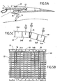
- FIGS. 5A to 5C A first embodiment of the invention applied to a forward-flow thrust reverser (ie in a direction opposite to the thrust direction of the aircraft) is illustrated in FIGS. 5A to 5C.
- FIG. 5A is a diagrammatic half-view, in longitudinal section, of a thrust reverser with deflection grids, the rollover of which is represented in the half-open position.
- FIG. 5B is a partial view from above of the nacelle, open cowling, revealing the grids of the thrust reverser and FIG. 5C showing in detail the interface between two adjacent or adjacent grids 22.
- the grid device (also called cascade) comprises means for redirecting forward (in the direction of the inversion flow) the parasitic flow created by the air leakage 32 and which was initially at the better neutral or worse thrust generator, so as to increase the efficiency of the inversion flow.
- the grid device is proceeded to the addition of aerodynamic appendages in the form of transverse blade tips 36 mounted on a longitudinal outer edge 22C of each grid 22 so as to fill the space resulting from the circular arrangement of the device to grids.
- Each grid is conventionally constituted by a plurality of transverse internal blades 24A and longitudinal internal blades 24B intersecting.
- these additional appendages are advantageously arranged in the extension of the transverse blades 24A and each have a curvature identical to that of the transverse blades.
- the blade tips 36 may be arranged differently, that is to say, not be aligned on the transverse blades.
- the number of blade tips may also be different from the total number of cross blades.
- the curvature of these blade tips may differ from that of the transverse blades.
- each blade tip may have a configuration different from its neighbor as well as each spacing.
- this addition of blade tips gives the grids a trapezoidal cross section compared to their initial rectangular section, thereby increasing the total air passage area through these grids.
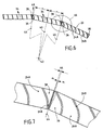
- FIG. 6 is a view showing a section in the axis of the nacelle by a plane passing through the grids of a thrust reversal device with exit on the side (ie in a direction perpendicular to the direction of thrust of the plane).
- the grid device comprises means for redirecting in the direction of the inversion flow the parasitic flow created by the air leakage 32.
- These means comprise tips of transverse blades 36, 38 fixed on the two edges. external longitudinal members 22C of each grid 22 so as to fill the space created by the initial longitudinal clearance 31 resulting from the curvatures of the transverse vanes 24B.
- the longitudinal cut of the blade tips 36, 38 is no longer parallel to an axis 40 passing through the center 42 of the nacelle and the center of the grid 22 but is now parallel to an axis 44 passing through the center 42 of the nacelle and the middle of the residual longitudinal clearance 46.
- the grid 22 is thus rather with a configuration in "trapezoid" and no longer parallelepiped, which as previously slightly increases the guide surface of the flow.
- the first is a residual leak 48 reported to dimensions comparable to a configuration of grids with forward exit.
- the second is an immediate taking into account of this residual leakage by the tips of blades which by this effect gives it a direction parallel to the inversion flow, either towards the front of the nacelle and no longer neutral or generating thrust.
- the inversion flows 34 coming out of the blades directly adjacent to the leak 48 are therefore less strongly disturbed. This results in a better efficiency of the inversion assembly allowing a reduction in the length of the grids, for the same efficiency, compared to the concept without fitting leaks.
- the mass of many components such as the operating cylinders of the movable cowl is reduced and the reliability of the system and components considered increased.
- the longitudinal blade 24B in contact with the blade tip 38 benefits from the trapezoidal extension of the configuration of the grid 22 and thus increases the total passage area of air through this grid.
- the initial leakage zone is thus filled by appropriate appendages improving the direction of the inversion flow through these leaks.
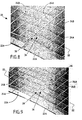
- FIG 8 shows in perspective the arrangement of two adjacent grids as shown in Figures 6 and 7.
- the tips of transverse blades 36, 38 are shown in the continuity of transverse blades 24A also called internal.
- this arrangement of blade tips is not mandatory, especially because each definition of vane can be different from one grid to another.
- blade tips 36 may not be aligned with blade tips 38.
- blade tip definitions 36, 38 may be specific and different transverse blades 24A of the same grid including shape, number and disposition, these parameters being chosen by the skilled person depending on the desired effect.
- FIG. 9 represents a solution to this problem by a single definition for the tips of transverse blades 36, 38.
- FIG. 10 A second exemplary embodiment of the invention is illustrated in FIG. 10. Indeed, it can be imagined that for a grid configuration that would be identical for all the inverter, the best solution would be to provide a single set of ends. blade 50 that can be mounted on one side or the other of the grid 22 and dimensioned so as to correspond to the full width between two longitudinal vanes 24B of two adjacent grids, to assembly and tolerance game by. The overall performance is thereby further enhanced with a significant improvement in weight gain and reliability.
- this arrangement can easily be applied to configurations already in operation without changing the structure of the surrounding components.
- the gain would then be a significant improvement of the inversion performance even for the same search reversal effectiveness of the inverter before setting up the panoplie, a possibility to use the engine speed at a lower level usually used , thus improving its longevity.
Landscapes
- Engineering & Computer Science (AREA)
- Chemical & Material Sciences (AREA)
- Combustion & Propulsion (AREA)
- Mechanical Engineering (AREA)
- General Engineering & Computer Science (AREA)
- Structures Of Non-Positive Displacement Pumps (AREA)
- Aerials With Secondary Devices (AREA)
- Endoscopes (AREA)
- Lasers (AREA)
- Electrical Discharge Machining, Electrochemical Machining, And Combined Machining (AREA)
- Devices For Blowing Cold Air, Devices For Blowing Warm Air, And Means For Preventing Water Condensation In Air Conditioning Units (AREA)
- Drying Of Solid Materials (AREA)
- Microwave Tubes (AREA)
Abstract
Description
La présente invention concerne les dispositifs d'inversion de poussée pour turboréacteur à double flux et elle se rapporte plus particulièrement à un perfectionnement aux grilles de dérivation de flux, dites aussi de déflection, utilisées dans de tels dispositifs.The present invention relates to thrust reverser devices for a turbofan engine and more particularly relates to an improvement to the flow bypass grids, also known as deflection grids, used in such devices.
Classiquement, un turboréacteur à double flux est équipé d'un conduit en arrière de la soufflante dont le but est de canaliser le flux secondaire dit froid. Ce conduit est constitué d'une paroi interne qui entoure la structure du moteur proprement dite en arrière de la soufflante, et d'une paroi externe dont la partie amont vient en continuité du carter moteur qui entoure cette soufflante. Cette paroi externe peut canaliser à la fois le flux secondaire et le flux primaire dans sa partie aval, et ceci en arrière de l'éjection du flux primaire, dit chaud, dans le cas de nacelle à flux mélangés ou à flux confluents par exemple. Par contre, dans le cas de nacelles dites à flux séparés, la paroi externe ne canalise que le flux secondaire.Conventionally, a turbofan engine is equipped with a duct behind the blower whose purpose is to channel the so-called cold secondary flow. This duct consists of an inner wall which surrounds the structure of the actual engine behind the blower, and an outer wall whose upstream portion is in continuity with the motor casing which surrounds this blower. This outer wall can channel both the secondary flow and the primary flow in its downstream part, and this behind the ejection of the primary flow, said hot, in the case of nacelle mixed flow or confluent flow for example. On the other hand, in the case of nacelles said to flow separated, the outer wall channels only the secondary flow.
Une paroi peut également caréner l'extérieur du moteur, c'est à dire l'extérieur du carter qui entoure la soufflante et l'extérieur de la paroi extérieure du conduit précité, ceci dans le but de minimiser la traînée de l'ensemble propulsif, notamment dans le cas d'ensembles propulsifs rapportés sur l'extérieur d'aéronef, comme ceux attachés sur ou sous les ailes ou à l'arrière du fuselage par exemple.A wall can also streamline the outside of the engine, that is to say the outside of the casing surrounding the blower and the outside of the outer wall of the aforementioned duct, this in order to minimize the drag of the propulsion unit , especially in the case of propulsion units reported on the outside of aircraft, such as those attached to or under the wings or the rear of the fuselage for example.
Le document WO 94/24430 décrit un dispositif à grilles pour la formation d'un flux d'inversion selon le préambule de revendication 1.WO 94/24430 discloses a grid device for the formation of an inversion flow according to the preamble of claim 1.
Les figures 1 à 3 illustrent un exemple connu de réalisation d'un inverseur de poussée à grilles de déflection appliqué à un turboréacteur à double flux.FIGS. 1 to 3 illustrate a known example of embodiment of a thrust reverser with deflection grids applied to a turbofan engine.
Un tel inverseur de poussée de turboréacteur 10 comporte un capotage mobile 12, constitué avantageusement de deux demi-parties cylindriques et formant, lors du fonctionnement du turboréacteur en poussée directe, tout ou partie de l'extrémité aval de la paroi externe du canal annulaire 14 de circulation de la veine de flux secondaire, et susceptible d'être déplacé axialement en direction aval au moyen d'un système de commande (non représenté) comportant par exemple des vérins fixés sur la partie amont de l'inverseur. Un déplacement du capotage vers l'aval entraîne le pivotement d'une pluralité de volets 16 par l'intermédiaire de biellettes de liaison 18 reliées à un point d'articulation de la paroi interne 20 du canal annulaire 14, ces volets venant obturer le canal et dévier le flux pour former un flux d'inversion dont le guidage est obtenu au moyen d'un dispositif à grilles 22 disposé sur la périphérie externe de ce canal et dont les grilles montées cote à cote sont découvertes après déplacement du capotage vers l'aval. Ces grilles comportent des aubages plus ou moins incurvés, dans une ou deux directions, selon la direction recherchée pour le flux d'inversion. En effet, lors de l'inversion de poussée, il est nécessaire d'orienter de façon déterminée la direction du flux passant au travers de certaines grilles du dispositif pour que l'air ne vienne pas impacter des zones de l'avion non désirées et évite le contact direct sur le sol, afin de minimiser voire annuler la possibilité d'ingestion par ricochet de cet air par le moteur générateur de ce flux ou d'un moteur proche. Cette orientation particulière des aubages évite en outre l'envoie de tout obstacle présent au niveau du tarmac sur des structures de l'avion, par le même phénomène de ricochet.Such a turbojet
Dans le dispositif à grilles illustré, chaque grille est montée dans un cadre parallélépipédique pour d'une part en faciliter l'installation et le remplacement sur la structure de la nacelle, notamment lors d'opérations de maintenance où le temps d'intervention a une très grande importance et donc doit être le plus réduit possible, et d'autre part assurer un meilleur aérodynamisme du flux d'inversion car la largeur de passage d'air doit être approximativement la même en entrée et en sortie, dans l'épaisseur de la grille. A cet effet, la configuration aérodynamique des aubes transversales 24A (les aubes longitudinales 24B étant droites) des grilles est définie pour transformer le flux de poussée passant aux travers d'elles en un flux d'inversion dirigé avantageusement vers l'avant de la nacelle.In the grid device shown, each grid is mounted in a parallelepiped frame to firstly facilitate the installation and the replacement on the nacelle structure, especially during maintenance operations where the intervention time is very important and therefore must be as small as possible, and secondly ensure better aerodynamics of the inversion flow because the air passage width must be approximately the same at the inlet and outlet, in the thickness of the grid. For this purpose, the aerodynamic configuration of the
La fixation de chaque grille sur la structure de la nacelle est assurée classiquement par des vis 23 traversant d'une part un bord transversal avant 22A et venant se fixer dans une partie structurale avant 26 de l'inverseur et d'autre part par un bord transversal arrière 22B venant se fixer dans une partie structurale arrière 28 de cet inverseur. Par contre, les grilles adjacentes ou mitoyennes ne sont pas liées entre-elles par leurs bords longitudinaux parallèles 22C et un jeu latéral 30 apparaît donc entre chaque grille du dispositif à grilles de l'inverseur de poussée.The fixing of each grid on the structure of the nacelle is conventionally provided by
En prenant en compte les tolérances de fabrication et d'installation, ce jeu peut s'avérer suffisamment large pour générer une fuite d'air 32 dans une direction verticale, voire dirigée vers l'arrière de la nacelle, particulièrement importante lors de l'inversion de poussée et venir réduire l'efficacité des deux flux d'inversion 34 sortant des grilles directement de part et d'autre de cette fuite 32, produisant ainsi une poussée vers l'arrière de la nacelle de nature à réduire fortement les performances de freinage aérodynamique de l'avion.Taking into account the manufacturing and installation tolerances, this clearance can be wide enough to generate an
Ce problème de fuite est aggravé avec une configuration de grilles à sortie vers le coté telle qu'illustrée à la figure 4 et dans laquelle, selon la direction d'inversion de flux recherchée, les aubes longitudinales 24B de ces grilles sont plus ou moins incurvés dans une même direction.This problem of leakage is aggravated with a configuration of exit grids to the side as shown in Figure 4 and in which, according to the desired flow reversal direction, the
Dans cette configuration, le jeu 31 est supérieur à celui correspondant à une grille à base parallélépipédique (exemple de la figure 3) et l'effet négatif du flux de fuite 32 sur les flux d'inversion directement à son contact se trouve de ce fait amplifié. Pour compenser cet effet négatif, il est classiquement procédé à un arrangement angulaire des aubes transversales 24A et suivant la nécessité, des aubes longitudinales 24B vers l'avant de la nacelle beaucoup plus fermé, obligeant une augmentation de la longueur des grilles pour en conserver la même section de passage d'air, ce qui implique une augmentation de la masse de nombreux composants notamment les vérins, touchant par la même à la fiabilité de ces organes.In this configuration, the
L'invention a pour objet un dispositif à grilles de déflection qui pallie ces inconvénients. Un but de l'invention est aussi de proposer un inverseur de poussée qui présente une facilité d'installation et de remplacement ou de maintenance de tout composant de la nacelle, notamment des grilles. En effet, en fonction de la position de la nacelle sur les ailes de l'avion, par exemple pour un quadrimoteur, la configuration du flux d'inversion peut être différente d'une nacelle à l'autre. Cela oblige à prévoir une panoplie de grilles de configuration d'aubes différentes mais adaptables et interchangeables entre-elles.The subject of the invention is a device with deflection grids which overcomes these disadvantages. An object of the invention is also to provide a thrust reverser which has an ease of installation and replacement or maintenance of any component of the nacelle, including grids. Indeed, depending on the position of the nacelle on the wings of the aircraft, for example for a four-engine, the configuration of the inversion flow may be different from one nacelle to another. This requires to provide a panoply of blade configuration grids different but adaptable and interchangeable between them.
Ces buts sont atteints par un dispositif selon la revendication 1, c'est à dire par un dispositif à grilles pour la formation d'un flux d'inversion à partir d'un flux de poussée de turboréacteur, comportant une pluralité de grilles de dérivation de flux disposées cote à cote à la périphérie externe d'un canal annulaire de circulation du flux de poussée, chaque grille étant constituée par une pluralité d'aubes internes transversales et d'aubes internes longitudinales entrecroisées, deux grilles adjacentes étant séparées par un jeu latéral générant un flux de fuite, caractérisé en ce qu'il comporte des moyens pour rediriger ledit flux de fuite dans une direction augmentant l'efficacité dudit flux d'inversion.These objects are achieved by a device according to claim 1, that is to say by a grid device for the formation of an inversion flow from a turbojet thrust flow, comprising a plurality of bypass grids of flow arranged side by side at the outer periphery of an annular channel for circulation of the thrust flow, each grid being constituted by a plurality of transverse internal blades and interlaced longitudinal internal blades, two adjacent grids being separated by a lateral clearance generating a leakage flow, characterized in that it comprises means for redirecting said leakage flux; in a direction increasing the efficiency of said inversion flow.
Ainsi, les fuites sont limitées et on obtient une re-direction du flux sortant des grilles vers la direction désirée.Thus, the leaks are limited and we obtain a re-direction of the flow out of the grids to the desired direction.
Avantageusement, les moyens pour rediriger le flux de fuite comportent des d'appendices aérodynamiques montés sur au moins ou sur les deux bords externes longitudinaux de chaque grille, ledit bord externe longitudinal de grille étant constitué de préférence par une aube longitudinale.Advantageously, the means for redirecting the leakage flow comprise aerodynamic appendages mounted on at least or on the two longitudinal outer edges of each grid, said longitudinal outer edge of the gate being preferably constituted by a longitudinal blade.
De préférence, lesdits appendices aérodynamiques comportent une pluralité de bouts d'aubes transversaux et chaque bout d'aube de ladite pluralité de bouts d'aubes transversaux d'une grille déterminée comporte une courbure identique ou différente de celle des aubes internes transversales de ladite grille. Chaque bout d'aube de ladite pluralité de bouts d'aubes transversaux d'une grille déterminée peut être disposé dans la continuité des aubes internes transversales de ladite grille et ladite pluralité de bouts d'aubes transversaux peut être disposée en nombre différent par rapport aux aubes internes transversales d'une même grille.Preferably, said aerodynamic appendages comprise a plurality of transverse blade tips and each blade tip of said plurality of transverse blade tips of a given grid has a curvature identical to or different from that of the transverse internal blades of said grid . Each blade tip of said plurality of transverse blade tips of a given grid may be disposed in the continuity of the transverse internal blades of said grid and said plurality of transverse blade tips may be arranged in a different number with respect to transverse internal blades of the same grid.
Selon une réalisation avantageuse, le nombre et la courbure de ladite pluralité de bouts d'aubes transversaux sont identiques pour toutes les grilles du dispositif quels que soient le nombre et la courbure des aubes internes transversales. Ainsi, il est possible d'adapter des appendices aérodynamiques à l'extérieur des aubes galbées longitudinales dans l'enveloppe initiale parallélépipédique et de permettre l'installation de n'importe quelle configuration de grilles entre-elles.According to an advantageous embodiment, the number and the curvature of said plurality of transverse blade tips are identical for all the grids of the device whatever the number and the curvature of the transverse internal blades. Thus, it is possible to adapt aerodynamic appendages outside the longitudinal curved vanes in the initial envelope parallelepiped and allow the installation of any configuration of grids between them.
D'autres caractéristiques et avantages de l'invention seront mieux compris à la lecture de la description qui va suivre de modes de réalisation préférentiels de l'invention en référence aux dessins annexés sur lesquels :
- La figure 1 représente une demi vue schématique, en coupe longitudinale, d'un inverseur de poussée à grilles de déflection selon l'art antérieur représenté en position fermée,
- La figure 2 représente une demi vue schématique, en coupe dans le plan des grilles, de l'inverseur de poussée de la figure 1.
- La figure 3 représente une loupe de la figure 2 illustrant la disposition mitoyenne des grilles de déflection,
- La figure 4 représente une disposition semblable à celle de la figure 3 appliquée à une variante d'art antérieur,
- La figure 5A représente une demi vue schématique, en coupe longitudinale, d'un inverseur de poussée à grilles de déflection selon un premier exemple de réalisation de l'invention représenté en position semi-ouvert,
- La figure 5B illustre une vue de dessus partielle de l'inverseur de poussée de la figure 5A limitée à son dispositif à grilles,
- La figure 5C représente une disposition semblable à celle de la figure 3 appliquée au premier exemple de réalisation de l'invention des figures 5A et 5B,
- La figure 6 représente une disposition semblable à celle de la figure 3 appliquée à un deuxième exemple de réalisation de l'invention,
- La figure 7 représente une loupe d'une partie d'extrémité d'une grille de déflection illustrée à la figure 6,
- La figure 8 représente une disposition latérale en perspective de deux grilles mitoyennes selon le deuxième exemple de réalisation de l'invention,
- La figure 9 représente une disposition latérale en perspective de deux grilles mitoyennes selon une variante du deuxième exemple de réalisation de l'invention, et
- La figure 10 représente une disposition semblable à celle de la figure 3 appliquée à un troisième exemple de réalisation de l'invention.
- FIG. 1 represents a schematic half-view, in longitudinal section, of a thrust reverser with deflection grids according to the prior art shown in the closed position,
- FIG. 2 represents a diagrammatic half-view, in section in the plane of the grids, of the thrust reverser of FIG. 1.
- FIG. 3 represents a magnifying glass of FIG. 2 illustrating the adjoining disposition of the deflection grids,
- FIG. 4 represents a layout similar to that of FIG. 3 applied to a variant of the prior art,
- FIG. 5A represents a schematic half-view, in longitudinal section, of a thrust reverser with deflection grids according to a first embodiment of the invention shown in a semi-open position,
- FIG. 5B illustrates a partial top view of the thrust reverser of FIG. 5A limited to its grid device,
- FIG. 5C represents a layout similar to that of FIG. 3 applied to the first embodiment of the invention of FIGS. 5A and 5B,
- FIG. 6 represents a layout similar to that of FIG. 3 applied to a second exemplary embodiment of the invention,
- FIG. 7 represents a magnifying glass of an end portion of a deflection grid shown in FIG. 6,
- FIG. 8 shows a lateral perspective view of two adjacent grids according to the second embodiment of the invention,
- FIG. 9 represents a lateral perspective view of two adjacent grids according to a variant of the second embodiment of the invention, and
- Figure 10 shows a similar arrangement to that of Figure 3 applied to a third embodiment of the invention.
Un premier exemple de réalisation de l'invention appliquée à un inverseur de poussée à flux de sortie vers l'avant (c'est à dire dans une direction opposée au sens de poussée de l'avion) est illustré aux figures 5A à 5C. La figure 5A est une demi vue schématique, en coupe longitudinale, d'un inverseur de poussée à grilles de déflection dont le capotage est représenté en position semi-ouvert. La figure 5B est une vue partielle de dessus de la nacelle, capotage ouvert, découvrant les grilles de l'inverseur de poussée et la figure 5C montre en détail l'interface entre deux grilles adjacentes ou mitoyennes 22.A first embodiment of the invention applied to a forward-flow thrust reverser (ie in a direction opposite to the thrust direction of the aircraft) is illustrated in FIGS. 5A to 5C. FIG. 5A is a diagrammatic half-view, in longitudinal section, of a thrust reverser with deflection grids, the rollover of which is represented in the half-open position. FIG. 5B is a partial view from above of the nacelle, open cowling, revealing the grids of the thrust reverser and FIG. 5C showing in detail the interface between two adjacent or
Selon l'invention, le dispositif à grilles (dit aussi à cascade) comporte des moyens pour rediriger vers l'avant (dans le sens du flux d'inversion) le flux parasite créé par la fuite d'air 32 et qui initialement était au mieux neutre ou pire générateur de poussée, de façon à augmenter l'efficacité du flux d'inversion. Pour ce faire, il est procédé à l'adjonction d'appendices aérodynamiques sous la forme de bouts d'aubes transversaux 36 montés sur un bord externe longitudinal 22C de chaque grille 22 de façon à combler l'espace résultant de la disposition circulaire du dispositif à grilles. Chaque grille est classiquement constituée par une pluralité d'aubes internes transversales 24A et d'aubes internes longitudinales 24B entrecroisées. Aussi, ces appendices additionnels sont avantageusement disposés dans le prolongement des aubes transversales 24A et présentent chacun une courbure identique à celle des aubes transversales. Ainsi, il est effectué une prise en compte immédiate de la fuite par les bouts d'aubes qui lui donne alors, comme pour ces aubes transversales, une direction vers l'avant de la nacelle. Toutefois, cette configuration n'est pas obligatoire et les bouts d'aubes 36 peuvent être disposés différemment, c'est à dire ne pas être alignés sur les aubes transversales. Le nombre de bouts d'aubes peut également être différent du nombre total des aubes transversales. La courbure de ces bouts d'aubes peut différer de celle des aubes transversales. Enfin, chaque bout d'aube peut présenter une configuration différente de son voisin de même que chaque espacement. En outre, cette adjonction de bouts d'aubes confère aux grilles une section transversale trapézoïdale comparativement à leur section rectangulaire initiale, augmentant ainsi la surface totale de passage d'air au travers de ces grilles.According to the invention, the grid device (also called cascade) comprises means for redirecting forward (in the direction of the inversion flow) the parasitic flow created by the
La figure 6 est une vue représentant une section dans l'axe de la nacelle par un plan passant par les grilles d'un dispositif d'inversion de poussée à sortie sur le coté (c'est à dire dans une direction perpendiculaire au sens de poussée de l'avion).FIG. 6 is a view showing a section in the axis of the nacelle by a plane passing through the grids of a thrust reversal device with exit on the side (ie in a direction perpendicular to the direction of thrust of the plane).
Dans cette configuration, le dispositif à grilles comporte des moyens pour rediriger dans le sens du flux d'inversion le flux parasite créé par la fuite d'air 32. Ces moyens comportent des bouts d'aubes transversaux 36, 38 fixés sur les deux bords externes longitudinaux 22C de chaque grille 22 de façon à combler l'espace créé par le jeu longitudinal initial 31 résultant des incurvations des aubes transversales 24B. La découpe longitudinale des bouts d'aubes 36, 38 n'est plus parallèle à un axe 40 passant par le centre 42 de la nacelle et le centre de la grille 22 mais est maintenant parallèle à un axe 44 passant par le centre 42 de la nacelle et le milieu du jeu longitudinal résiduel 46. La grille 22 se présente ainsi plutôt avec une configuration en "trapèze" et non plus en parallélépipède, ce qui comme précédemment augmente légèrement la surface de guidage du flux.In this configuration, the grid device comprises means for redirecting in the direction of the inversion flow the parasitic flow created by the
Deux avantages apparaissent en outre dans cette configuration. Le premier est une fuite résiduelle 48 reportée à des dimensions comparables à une configuration de grilles à sortie vers l'avant. Le second est une prise en compte immédiate de cette fuite résiduelle par les bouts d'aubes qui par cet effet lui donne une direction parallèle au flux d'inversion, soit vers l'avant de la nacelle et non plus neutre ou génératrice de poussée. Les flux d'inversion 34 sortant des aubes directement mitoyennes à la fuite 48 sont par la même moins fortement perturbés. Il en résulte une meilleure efficacité de l'ensemble d'inversion permettant une réduction de la longueur de grilles, pour une même efficacité, comparée au concept sans aménagement des fuites. La masse de nombreux composants tel les vérins d'actionnement du capot mobile s'en trouve réduite et la fiabilité du système et des composants considérés augmentée.Two advantages also appear in this configuration. The first is a
De plus, on le voit sur la loupe de la figure 7, l'aube longitudinale 24B au contact du bout d'aube 38 bénéficie de l'extension trapézoïdale de la configuration de la grille 22 et augmente ainsi la surface totale de passage d'air au travers de cette grille. La zone de fuite initiale est ainsi comblée par des appendices appropriés améliorant la direction du flux d'inversion passant par ces fuites.Moreover, as can be seen on the magnifying glass of FIG. 7, the
La figure 8 montre en perspective la disposition de deux grilles mitoyennes comme montrées dans les figures 6 et 7. Dans cette configuration, les bouts d'aubes transversaux 36, 38 sont représentés dans la continuité des aubes transversales 24A dites aussi internes. Toutefois, cette disposition des bouts d'aubes n'est pas obligatoire, du fait notamment que chaque définition d'aubage peut être différente d'une grille à l'autre. Ainsi, comme dans le mode de réalisation précédent, des bouts d'aubes 36 peuvent ne pas être alignées avec les bouts d'aubes 38. De même, on peut noter que les définitions des bouts d'aubes 36, 38 peuvent être spécifiques et différentes des aubes transversales 24A d'une même grille notamment en forme, nombre et disposition, ces paramètres étant choisis par l'homme de métier en fonction de l'effet recherché.Figure 8 shows in perspective the arrangement of two adjacent grids as shown in Figures 6 and 7. In this configuration, the tips of
La figure 9 représente une solution à ce problème par une définition unique pour les bouts d'aubes transversaux 36, 38. Par cette configuration remarquable, les bouts d'aubes 36 appliqués sur n'importe quelle configuration de grille se retrouve toujours en correspondance avec les bouts d'aubes 38 de n'importe quelle autre configuration de grille, assurant ainsi une performance aérodynamique de la fuite optimale.FIG. 9 represents a solution to this problem by a single definition for the tips of
Un second exemple de réalisation de l'invention est illustré à la figure 10. En effet, on peut imaginer que pour une configuration de grille qui serait identique pour tout l'inverseur, la solution la mieux adaptée serait de fournir un unique ensemble de bouts d'aubes 50 pouvant être monté d'un côté ou de l'autre de la grille 22 et dimensionné de façon à correspondre à la largeur complète entre deux aubes longitudinales 24B de deux grilles mitoyennes, au jeu de montage et de tolérance près. La performance globale se trouve de ce fait encore renforcée avec une amélioration sensible en gain de masse et de fiabilité.A second exemplary embodiment of the invention is illustrated in FIG. 10. Indeed, it can be imagined that for a grid configuration that would be identical for all the inverter, the best solution would be to provide a single set of ends.
En outre, cette disposition peut s'appliquer aisément sur des configurations déjà en exploitation sans changer la structure des composants environnants. Le gain serait alors une amélioration sensible des performances d'inversion voire pour une même recherche d'efficacité d'inversion de l'inverseur avant mise en place de la panoplie, une possibilité d'utiliser le régime du moteur à un niveau inférieur habituellement utilisé, améliorant ainsi sa longévité.In addition, this arrangement can easily be applied to configurations already in operation without changing the structure of the surrounding components. The gain would then be a significant improvement of the inversion performance even for the same search reversal effectiveness of the inverter before setting up the panoplie, a possibility to use the engine speed at a lower level usually used , thus improving its longevity.
Claims (11)
- Cascade device for the formation of a reversal flow (34) from a thrust flow of a turbojet engine, comprising a plurality of flow diverter cascades (22) arranged side-by-side on the external periphery of an annular duct (14) for circulating the thrust flow, each cascade consisting of a plurality of transverse internal vanes (24A) and longitudinal internal vanes (24B) crossing one another, two adjacent cascades being separated by a lateral clearance (30, 31) generating a leakage flow (32), characterised in that it comprises means for redirecting said leakage flow in a direction increasing the effectiveness of said reversal flow.
- Cascade device according to Claim 1, characterised in that said means for redirecting the leakage flow comprise aerodynamic appendages (36, 38) mounted on at least one longitudinal external edge (22C) of each cascade.
- Cascade device according to Claim 2, characterised in that the aerodynamic appendages (36, 38) are mounted on the two longitudinal external edges (22C) of each cascade.
- Cascade device according to Claim 2 or Claim 3, characterised in that said longitudinal external edge of the cascade consists of a longitudinal vane (24B).
- Cascade device according to Claim 2, characterised in that said aerodynamic appendages comprise a plurality of transverse vane tips (36, 38).
- Cascade device according to Claim 5, characterised in that each vane tip of said plurality of transverse vane tips of a given cascade, has an identical curvature to that of the transverse internal vanes (24A) of said cascade.
- Cascade device according to Claim 5, characterised in that each vane tip of said plurality of transverse vane tips of a given cascade, has a different curvature from that of the transverse internal vanes (24A) of said cascade.
- Cascade device according to Claim 5, characterised in that each vane tip of said plurality of transverse vane tips of a given cascade is arranged in the continuation of the transverse internal vanes (24A) of said cascade.
- Cascade device according to Claim 5, characterised in that said plurality of transverse vane tips is arranged in a different number relative to the transverse internal vanes (24A) of the same cascade.
- Cascade device according to Claim 5, characterised in that the number and the curvature of said plurality of transverse vane tips are identical for all the cascades of the device, regardless of the number and curvature of the transverse internal vanes.
- Thrust reverser for a bypass turbojet engine comprising a cascade device according to any one of Claims 1 to 10.
Applications Claiming Priority (3)
| Application Number | Priority Date | Filing Date | Title |
|---|---|---|---|
| FR0216634A FR2849113B1 (en) | 2002-12-24 | 2002-12-24 | THRUST INVERTER WITH OPTIMIZED DEFLECTION GRIDS |
| FR0216634 | 2002-12-24 | ||
| PCT/FR2003/003868 WO2004059157A1 (en) | 2002-12-24 | 2003-12-22 | Thrust reverser comprising optimised deflector gratings |
Publications (2)
| Publication Number | Publication Date |
|---|---|
| EP1579112A1 EP1579112A1 (en) | 2005-09-28 |
| EP1579112B1 true EP1579112B1 (en) | 2007-05-16 |
Family
ID=32406491
Family Applications (1)
| Application Number | Title | Priority Date | Filing Date |
|---|---|---|---|
| EP03799686A Expired - Lifetime EP1579112B1 (en) | 2002-12-24 | 2003-12-22 | Thrust reverser comprising optimised deflector gratings |
Country Status (9)
| Country | Link |
|---|---|
| US (1) | US7484355B2 (en) |
| EP (1) | EP1579112B1 (en) |
| AT (1) | ATE362583T1 (en) |
| AU (1) | AU2003299392A1 (en) |
| CA (1) | CA2511432C (en) |
| DE (1) | DE60313893T2 (en) |
| ES (1) | ES2285255T3 (en) |
| FR (1) | FR2849113B1 (en) |
| WO (1) | WO2004059157A1 (en) |
Families Citing this family (25)
| Publication number | Priority date | Publication date | Assignee | Title |
|---|---|---|---|---|
| US8015797B2 (en) | 2006-09-21 | 2011-09-13 | Jean-Pierre Lair | Thrust reverser nozzle for a turbofan gas turbine engine |
| FR2920199B1 (en) * | 2007-08-20 | 2009-10-30 | Aircelle Sa | MOBILE REVERSE INVERTER COVER AND THRUST REVERSER EQUIPPED WITH SUCH A MOBILE HOOD |
| US7735778B2 (en) | 2007-11-16 | 2010-06-15 | Pratt & Whitney Canada Corp. | Pivoting fairings for a thrust reverser |
| US8052086B2 (en) | 2007-11-16 | 2011-11-08 | The Nordam Group, Inc. | Thrust reverser door |
| US8052085B2 (en) | 2007-11-16 | 2011-11-08 | The Nordam Group, Inc. | Thrust reverser for a turbofan gas turbine engine |
| US8172175B2 (en) | 2007-11-16 | 2012-05-08 | The Nordam Group, Inc. | Pivoting door thrust reverser for a turbofan gas turbine engine |
| US8051639B2 (en) * | 2007-11-16 | 2011-11-08 | The Nordam Group, Inc. | Thrust reverser |
| US8091827B2 (en) | 2007-11-16 | 2012-01-10 | The Nordam Group, Inc. | Thrust reverser door |
| US8127530B2 (en) | 2008-06-19 | 2012-03-06 | The Nordam Group, Inc. | Thrust reverser for a turbofan gas turbine engine |
| FR2960918B1 (en) | 2010-06-08 | 2012-05-25 | Aircelle Sa | AUTOSUPPORTE TYPE DEVIATION GRID FOR PUSH INVERTER |
| FR2965589B1 (en) * | 2010-10-04 | 2015-05-15 | Aircelle Sa | PUSH INVERTER |
| US10006404B2 (en) | 2012-02-28 | 2018-06-26 | United Technologies Corporation | Gas turbine engine thrust reverser system |
| FR2995026B1 (en) * | 2012-09-03 | 2019-06-07 | Safran Nacelles | FRONT FRAME FOR A DEVIATION GRID REVERSING INVERTER STRUCTURE |
| DE102014210025A1 (en) * | 2014-05-26 | 2015-12-17 | Rolls-Royce Deutschland Ltd & Co Kg | Thrust reverser cascade element of an aircraft gas turbine |
| US10309343B2 (en) * | 2014-11-06 | 2019-06-04 | Rohr, Inc. | Split sleeve hidden door thrust reverser |
| US10018151B2 (en) | 2015-01-14 | 2018-07-10 | The Boeing Company | Methods and apparatus to vary reverse thrust of aircraft engines |
| US9874176B2 (en) * | 2015-01-14 | 2018-01-23 | The Boeing Company | Methods and apparatus to vary reverse thrust of aircraft engines |
| US10221859B2 (en) | 2016-02-08 | 2019-03-05 | General Electric Company | Turbine engine compressor blade |
| US10823112B2 (en) * | 2017-05-25 | 2020-11-03 | The Boeing Company | Method for manufacturing and assembly of a thrust reverser cascade |
| US10865736B2 (en) * | 2017-10-18 | 2020-12-15 | Spirit Aerosystems, Inc. | Cascade segment for thrust reverser with repeating modular units, and method of manufacturing same |
| FR3074855A1 (en) * | 2017-12-11 | 2019-06-14 | Airbus Operations | GRID FOR FORMATION OF AN INVERSION FLOW OF AN AIRCRAFT TURBOJET ENGINE |
| FR3082889A1 (en) * | 2018-06-26 | 2019-12-27 | Airbus Operations | TURBOREACTOR COMPRISING A NACELLE EQUIPPED WITH REVERSING SHUTTERS PROVIDED WITH MEANS FOR GENERATING VORTS |
| FR3110639B1 (en) * | 2020-05-20 | 2022-09-16 | Safran Nacelles | THRUST REVERSER FOR A NACELLE OF A DOUBLE-FLOW AIRCRAFT TURBOJET |
| EP4083410A3 (en) * | 2021-04-08 | 2023-01-11 | Rohr, Inc. | Thrust reverser system for an aircraft propulsion system |
| FR3148222A1 (en) * | 2023-04-26 | 2024-11-01 | Airbus Operations (S.A.S.) | Aircraft nacelle equipped with at least one thrust reverser device comprising at least one longitudinal deflector, aircraft comprising at least one propulsion assembly comprising such a nacelle |
Family Cites Families (22)
| Publication number | Priority date | Publication date | Assignee | Title |
|---|---|---|---|---|
| GB882424A (en) * | 1958-04-03 | 1961-11-15 | Rolls Royce | Improvements in or relating to aircraft jet propulsion apparatus |
| FR2096650B1 (en) * | 1970-04-21 | 1974-03-01 | Snecma | |
| US3601992A (en) * | 1970-06-10 | 1971-08-31 | Rohr Corp | Thrust reversing apparatus |
| US3941313A (en) * | 1972-03-06 | 1976-03-02 | Societe Nationale D'etude Et De Construction De Moteurs D'aviation | Jet engine nacelle with drag augmenter auxiliary for thrust-reverser system |
| US4026105A (en) * | 1975-03-25 | 1977-05-31 | The Boeing Company | Jet engine thrust reverser |
| US3981451A (en) * | 1975-11-17 | 1976-09-21 | Rohr Industries, Inc. | Fan cascade thrust reverser |
| US4067094A (en) * | 1976-04-26 | 1978-01-10 | Harry Feick Co., Inc. | Load bearing vane structure for thrust reversal |
| GB1583952A (en) * | 1976-07-13 | 1981-02-04 | Short Brothers & Harland Ltd | Gas turbine engines |
| US4278220A (en) * | 1979-03-30 | 1981-07-14 | The United States Of America As Represented By The Administrator Of The National Aeronautics And Space Administration | Thrust reverser for a long duct fan engine |
| US4373328A (en) * | 1980-10-22 | 1983-02-15 | United Technologies Corporation | Thrust reverser |
| US4778110A (en) * | 1982-09-30 | 1988-10-18 | Rohr Industries, Inc. | Modular composite cascade assembly |
| GB2182724B (en) * | 1985-10-08 | 1988-12-07 | Rolls Royce | Gas turbine engine thrust reverser |
| FR2651278B1 (en) * | 1989-08-23 | 1994-05-06 | Hispano Suiza | INVERTER WITH GRIDS WITHOUT SLIDING COVER FOR TURBOREACTOR. |
| US5507143A (en) * | 1993-04-13 | 1996-04-16 | The Boeing Company | Cascade assembly for use in a thrust-reversing mechanism |
| GB9723022D0 (en) * | 1997-11-01 | 1998-01-07 | Rolls Royce Plc | Gas turbine apparatus |
| GB2347126B (en) * | 1999-02-23 | 2003-02-12 | Rolls Royce Plc | Thrust reverser |
| GB0001279D0 (en) * | 2000-01-21 | 2000-03-08 | Rolls Royce Plc | A flow directing element and a method of manufacturing a flow directing element |
| US6584763B2 (en) * | 2001-08-01 | 2003-07-01 | Rohr, Inc. | Lock for the translating sleeve of a turbofan engine thrust reverser |
| US6786039B2 (en) * | 2001-09-07 | 2004-09-07 | Honeywell International, Inc. | Thrust reverser actuator with an automatic relock and lock drop prevention mechanism |
| FR2830051B1 (en) * | 2001-09-27 | 2003-11-07 | Hurel Hispano Le Havre | LOCKING SYSTEM ON A GRID DRIVE INVERTER |
| GB0608985D0 (en) * | 2006-05-06 | 2006-06-14 | Rolls Royce Plc | Aeroengine thrust reverser |
| US7836681B2 (en) * | 2006-06-13 | 2010-11-23 | Rolls-Royce Corporation | Mechanism for a vectoring exhaust nozzle |
-
2002
- 2002-12-24 FR FR0216634A patent/FR2849113B1/en not_active Expired - Fee Related
-
2003
- 2003-12-22 AT AT03799686T patent/ATE362583T1/en not_active IP Right Cessation
- 2003-12-22 ES ES03799686T patent/ES2285255T3/en not_active Expired - Lifetime
- 2003-12-22 US US10/536,308 patent/US7484355B2/en not_active Expired - Fee Related
- 2003-12-22 EP EP03799686A patent/EP1579112B1/en not_active Expired - Lifetime
- 2003-12-22 DE DE60313893T patent/DE60313893T2/en not_active Expired - Lifetime
- 2003-12-22 CA CA002511432A patent/CA2511432C/en not_active Expired - Fee Related
- 2003-12-22 AU AU2003299392A patent/AU2003299392A1/en not_active Abandoned
- 2003-12-22 WO PCT/FR2003/003868 patent/WO2004059157A1/en not_active Ceased
Also Published As
| Publication number | Publication date |
|---|---|
| CA2511432A1 (en) | 2004-07-15 |
| ES2285255T3 (en) | 2007-11-16 |
| DE60313893D1 (en) | 2007-06-28 |
| FR2849113B1 (en) | 2005-02-04 |
| CA2511432C (en) | 2009-09-22 |
| AU2003299392A1 (en) | 2004-07-22 |
| US20060005530A1 (en) | 2006-01-12 |
| EP1579112A1 (en) | 2005-09-28 |
| WO2004059157A1 (en) | 2004-07-15 |
| ATE362583T1 (en) | 2007-06-15 |
| US7484355B2 (en) | 2009-02-03 |
| FR2849113A1 (en) | 2004-06-25 |
| DE60313893T2 (en) | 2008-01-17 |
Similar Documents
| Publication | Publication Date | Title |
|---|---|---|
| EP1579112B1 (en) | Thrust reverser comprising optimised deflector gratings | |
| EP0848153B1 (en) | Thrust reverser for a jet engine with blockdoors and deflector vanes linked to the fixed frame | |
| EP0822327B1 (en) | Thrust reverser for a turbofan engine with thrust reverser doors which form scoops | |
| EP0534815B2 (en) | Thrust-reverser with improved guidance of the reversed jets | |
| CA2318373C (en) | Thrust reverser with turning vanes capable of being superposed | |
| EP2739841B1 (en) | Reverser having movable cascades, and translatably variable nozzle | |
| WO1999046498A1 (en) | Turbojet thrust reverser with doors forming scoops associated with a mobile grating | |
| FR2777043A1 (en) | TURBOSPROCKET DRIVE WITH SCOOPING DOORS ASSOCIATED WITH AN ARTICULATED EXTERNAL COVER | |
| EP0774578B1 (en) | Thrust reverser for a turbojet where the reversing shells are balanced to stay in the closed position | |
| FR2748525A1 (en) | TURBOREACTOR DRIVE INVERTER WITH DOORS WITH DEFLECTIVE BLADES | |
| FR2774431A1 (en) | DOWNSTREAM OBSTACLE TURBOREACTOR DRIVER | |
| EP3740666B1 (en) | Rear assembly of a nacelle of a turbojet engine of an aircraft comprising a sliding cascade thrust reverser | |
| WO2010012878A1 (en) | Thrust reverser device | |
| FR2766522A1 (en) | TURBO BLOWER THRUST INVERTER WITH OBSTACLE WITH AXIAL GUIDANCE LINKED TO THE PRIMARY COVER | |
| CA2152883C (en) | Turbofan thrust reverser, with obstructions linked to the primary enclosure | |
| EP0821151A1 (en) | Thrust reverser for a jet engine with doors with a sliding panel | |
| EP4293215A1 (en) | Aircraft engine nacelle provided with a thrust reverser with a mobile ejection structure | |
| WO2014191696A1 (en) | Turbojet engine nacelle comprising a thrust reversing device with doors, comprising inner flanks on the sides of the opening | |
| WO2021136900A1 (en) | Door thrust reverser comprising a deflector for redirecting an air flow to a tail unit | |
| WO2021136903A1 (en) | Door thrust reverser comprising a deflector for redirecting an air flow in the upstream direction |
Legal Events
| Date | Code | Title | Description |
|---|---|---|---|
| PUAI | Public reference made under article 153(3) epc to a published international application that has entered the european phase |
Free format text: ORIGINAL CODE: 0009012 |
|
| 17P | Request for examination filed |
Effective date: 20050421 |
|
| AK | Designated contracting states |
Kind code of ref document: A1 Designated state(s): AT BE BG CH CY CZ DE DK EE ES FI FR GB GR HU IE IT LI LU MC NL PT RO SE SI SK TR |
|
| AX | Request for extension of the european patent |
Extension state: AL LT LV MK |
|
| RAP1 | Party data changed (applicant data changed or rights of an application transferred) |
Owner name: AIRCELLE |
|
| DAX | Request for extension of the european patent (deleted) | ||
| RIN1 | Information on inventor provided before grant (corrected) |
Inventor name: BLIN, LAURENT Inventor name: VAUCHEL, GUY Inventor name: CAZUC, XAVIER |
|
| GRAP | Despatch of communication of intention to grant a patent |
Free format text: ORIGINAL CODE: EPIDOSNIGR1 |
|
| GRAS | Grant fee paid |
Free format text: ORIGINAL CODE: EPIDOSNIGR3 |
|
| GRAA | (expected) grant |
Free format text: ORIGINAL CODE: 0009210 |
|
| AK | Designated contracting states |
Kind code of ref document: B1 Designated state(s): AT BE BG CH CY CZ DE DK EE ES FI FR GB GR HU IE IT LI LU MC NL PT RO SE SI SK TR |
|
| PG25 | Lapsed in a contracting state [announced via postgrant information from national office to epo] |
Ref country code: FI Free format text: LAPSE BECAUSE OF FAILURE TO SUBMIT A TRANSLATION OF THE DESCRIPTION OR TO PAY THE FEE WITHIN THE PRESCRIBED TIME-LIMIT Effective date: 20070516 |
|
| REG | Reference to a national code |
Ref country code: GB Ref legal event code: FG4D Free format text: NOT ENGLISH |
|
| GBT | Gb: translation of ep patent filed (gb section 77(6)(a)/1977) |
Effective date: 20070516 |
|
| REG | Reference to a national code |
Ref country code: CH Ref legal event code: EP |
|
| REG | Reference to a national code |
Ref country code: IE Ref legal event code: FG4D Free format text: LANGUAGE OF EP DOCUMENT: FRENCH |
|
| REF | Corresponds to: |
Ref document number: 60313893 Country of ref document: DE Date of ref document: 20070628 Kind code of ref document: P |
|
| PG25 | Lapsed in a contracting state [announced via postgrant information from national office to epo] |
Ref country code: SE Free format text: LAPSE BECAUSE OF FAILURE TO SUBMIT A TRANSLATION OF THE DESCRIPTION OR TO PAY THE FEE WITHIN THE PRESCRIBED TIME-LIMIT Effective date: 20070816 |
|
| NLV1 | Nl: lapsed or annulled due to failure to fulfill the requirements of art. 29p and 29m of the patents act | ||
| REG | Reference to a national code |
Ref country code: ES Ref legal event code: FG2A Ref document number: 2285255 Country of ref document: ES Kind code of ref document: T3 |
|
| PG25 | Lapsed in a contracting state [announced via postgrant information from national office to epo] |
Ref country code: AT Free format text: LAPSE BECAUSE OF FAILURE TO SUBMIT A TRANSLATION OF THE DESCRIPTION OR TO PAY THE FEE WITHIN THE PRESCRIBED TIME-LIMIT Effective date: 20070516 |
|
| REG | Reference to a national code |
Ref country code: IE Ref legal event code: FD4D |
|
| PG25 | Lapsed in a contracting state [announced via postgrant information from national office to epo] |
Ref country code: PT Free format text: LAPSE BECAUSE OF FAILURE TO SUBMIT A TRANSLATION OF THE DESCRIPTION OR TO PAY THE FEE WITHIN THE PRESCRIBED TIME-LIMIT Effective date: 20071016 Ref country code: CZ Free format text: LAPSE BECAUSE OF FAILURE TO SUBMIT A TRANSLATION OF THE DESCRIPTION OR TO PAY THE FEE WITHIN THE PRESCRIBED TIME-LIMIT Effective date: 20070516 Ref country code: SI Free format text: LAPSE BECAUSE OF FAILURE TO SUBMIT A TRANSLATION OF THE DESCRIPTION OR TO PAY THE FEE WITHIN THE PRESCRIBED TIME-LIMIT Effective date: 20070516 Ref country code: DK Free format text: LAPSE BECAUSE OF FAILURE TO SUBMIT A TRANSLATION OF THE DESCRIPTION OR TO PAY THE FEE WITHIN THE PRESCRIBED TIME-LIMIT Effective date: 20070516 Ref country code: NL Free format text: LAPSE BECAUSE OF FAILURE TO SUBMIT A TRANSLATION OF THE DESCRIPTION OR TO PAY THE FEE WITHIN THE PRESCRIBED TIME-LIMIT Effective date: 20070516 Ref country code: BG Free format text: LAPSE BECAUSE OF FAILURE TO SUBMIT A TRANSLATION OF THE DESCRIPTION OR TO PAY THE FEE WITHIN THE PRESCRIBED TIME-LIMIT Effective date: 20070816 Ref country code: IE Free format text: LAPSE BECAUSE OF FAILURE TO SUBMIT A TRANSLATION OF THE DESCRIPTION OR TO PAY THE FEE WITHIN THE PRESCRIBED TIME-LIMIT Effective date: 20070516 |
|
| PG25 | Lapsed in a contracting state [announced via postgrant information from national office to epo] |
Ref country code: SK Free format text: LAPSE BECAUSE OF FAILURE TO SUBMIT A TRANSLATION OF THE DESCRIPTION OR TO PAY THE FEE WITHIN THE PRESCRIBED TIME-LIMIT Effective date: 20070516 |
|
| PLBE | No opposition filed within time limit |
Free format text: ORIGINAL CODE: 0009261 |
|
| STAA | Information on the status of an ep patent application or granted ep patent |
Free format text: STATUS: NO OPPOSITION FILED WITHIN TIME LIMIT |
|
| 26N | No opposition filed |
Effective date: 20080219 |
|
| PG25 | Lapsed in a contracting state [announced via postgrant information from national office to epo] |
Ref country code: GR Free format text: LAPSE BECAUSE OF FAILURE TO SUBMIT A TRANSLATION OF THE DESCRIPTION OR TO PAY THE FEE WITHIN THE PRESCRIBED TIME-LIMIT Effective date: 20070817 |
|
| PG25 | Lapsed in a contracting state [announced via postgrant information from national office to epo] |
Ref country code: RO Free format text: LAPSE BECAUSE OF FAILURE TO SUBMIT A TRANSLATION OF THE DESCRIPTION OR TO PAY THE FEE WITHIN THE PRESCRIBED TIME-LIMIT Effective date: 20070516 |
|
| BERE | Be: lapsed |
Owner name: AIRCELLE Effective date: 20071231 |
|
| PG25 | Lapsed in a contracting state [announced via postgrant information from national office to epo] |
Ref country code: MC Free format text: LAPSE BECAUSE OF NON-PAYMENT OF DUE FEES Effective date: 20071231 |
|
| REG | Reference to a national code |
Ref country code: CH Ref legal event code: PL |
|
| PG25 | Lapsed in a contracting state [announced via postgrant information from national office to epo] |
Ref country code: BE Free format text: LAPSE BECAUSE OF NON-PAYMENT OF DUE FEES Effective date: 20071231 |
|
| PG25 | Lapsed in a contracting state [announced via postgrant information from national office to epo] |
Ref country code: LI Free format text: LAPSE BECAUSE OF NON-PAYMENT OF DUE FEES Effective date: 20071231 Ref country code: CH Free format text: LAPSE BECAUSE OF NON-PAYMENT OF DUE FEES Effective date: 20071231 |
|
| PG25 | Lapsed in a contracting state [announced via postgrant information from national office to epo] |
Ref country code: EE Free format text: LAPSE BECAUSE OF FAILURE TO SUBMIT A TRANSLATION OF THE DESCRIPTION OR TO PAY THE FEE WITHIN THE PRESCRIBED TIME-LIMIT Effective date: 20070516 |
|
| PG25 | Lapsed in a contracting state [announced via postgrant information from national office to epo] |
Ref country code: CY Free format text: LAPSE BECAUSE OF FAILURE TO SUBMIT A TRANSLATION OF THE DESCRIPTION OR TO PAY THE FEE WITHIN THE PRESCRIBED TIME-LIMIT Effective date: 20070516 |
|
| PG25 | Lapsed in a contracting state [announced via postgrant information from national office to epo] |
Ref country code: LU Free format text: LAPSE BECAUSE OF NON-PAYMENT OF DUE FEES Effective date: 20071222 |
|
| PG25 | Lapsed in a contracting state [announced via postgrant information from national office to epo] |
Ref country code: HU Free format text: LAPSE BECAUSE OF FAILURE TO SUBMIT A TRANSLATION OF THE DESCRIPTION OR TO PAY THE FEE WITHIN THE PRESCRIBED TIME-LIMIT Effective date: 20071117 Ref country code: TR Free format text: LAPSE BECAUSE OF FAILURE TO SUBMIT A TRANSLATION OF THE DESCRIPTION OR TO PAY THE FEE WITHIN THE PRESCRIBED TIME-LIMIT Effective date: 20070516 |
|
| PGFP | Annual fee paid to national office [announced via postgrant information from national office to epo] |
Ref country code: ES Payment date: 20141224 Year of fee payment: 12 Ref country code: FR Payment date: 20141031 Year of fee payment: 12 Ref country code: DE Payment date: 20141029 Year of fee payment: 12 Ref country code: GB Payment date: 20141023 Year of fee payment: 12 |
|
| PGFP | Annual fee paid to national office [announced via postgrant information from national office to epo] |
Ref country code: IT Payment date: 20141222 Year of fee payment: 12 |
|
| REG | Reference to a national code |
Ref country code: DE Ref legal event code: R119 Ref document number: 60313893 Country of ref document: DE |
|
| GBPC | Gb: european patent ceased through non-payment of renewal fee |
Effective date: 20151222 |
|
| REG | Reference to a national code |
Ref country code: FR Ref legal event code: ST Effective date: 20160831 |
|
| PG25 | Lapsed in a contracting state [announced via postgrant information from national office to epo] |
Ref country code: GB Free format text: LAPSE BECAUSE OF NON-PAYMENT OF DUE FEES Effective date: 20151222 Ref country code: DE Free format text: LAPSE BECAUSE OF NON-PAYMENT OF DUE FEES Effective date: 20160701 |
|
| PG25 | Lapsed in a contracting state [announced via postgrant information from national office to epo] |
Ref country code: FR Free format text: LAPSE BECAUSE OF NON-PAYMENT OF DUE FEES Effective date: 20151231 |
|
| PG25 | Lapsed in a contracting state [announced via postgrant information from national office to epo] |
Ref country code: IT Free format text: LAPSE BECAUSE OF NON-PAYMENT OF DUE FEES Effective date: 20151222 |
|
| REG | Reference to a national code |
Ref country code: ES Ref legal event code: FD2A Effective date: 20170126 |
|
| PG25 | Lapsed in a contracting state [announced via postgrant information from national office to epo] |
Ref country code: ES Free format text: LAPSE BECAUSE OF NON-PAYMENT OF DUE FEES Effective date: 20151223 |