EP1578663B1 - Perforated skin structure for laminar-flow systems - Google Patents
Perforated skin structure for laminar-flow systems Download PDFInfo
- Publication number
- EP1578663B1 EP1578663B1 EP03724090.0A EP03724090A EP1578663B1 EP 1578663 B1 EP1578663 B1 EP 1578663B1 EP 03724090 A EP03724090 A EP 03724090A EP 1578663 B1 EP1578663 B1 EP 1578663B1
- Authority
- EP
- European Patent Office
- Prior art keywords
- perforations
- flow
- bundles
- bundle
- slots
- Prior art date
- Legal status (The legal status is an assumption and is not a legal conclusion. Google has not performed a legal analysis and makes no representation as to the accuracy of the status listed.)
- Expired - Lifetime
Links
- 230000001066 destructive effect Effects 0.000 claims description 14
- 239000007787 solid Substances 0.000 claims 1
- 238000001228 spectrum Methods 0.000 description 26
- 238000009826 distribution Methods 0.000 description 17
- 238000003754 machining Methods 0.000 description 10
- 239000006185 dispersion Substances 0.000 description 8
- 230000003595 spectral effect Effects 0.000 description 8
- 230000000694 effects Effects 0.000 description 7
- 239000012530 fluid Substances 0.000 description 6
- 230000009931 harmful effect Effects 0.000 description 6
- 230000007704 transition Effects 0.000 description 6
- 230000004907 flux Effects 0.000 description 5
- 230000009467 reduction Effects 0.000 description 5
- 238000013461 design Methods 0.000 description 4
- 238000010586 diagram Methods 0.000 description 4
- 239000003381 stabilizer Substances 0.000 description 4
- 230000008859 change Effects 0.000 description 3
- 238000010276 construction Methods 0.000 description 3
- 238000011161 development Methods 0.000 description 3
- 230000005284 excitation Effects 0.000 description 3
- 238000002474 experimental method Methods 0.000 description 3
- 238000000034 method Methods 0.000 description 3
- 238000000926 separation method Methods 0.000 description 3
- 238000001125 extrusion Methods 0.000 description 2
- 238000005457 optimization Methods 0.000 description 2
- 230000000737 periodic effect Effects 0.000 description 2
- 230000000087 stabilizing effect Effects 0.000 description 2
- 238000012935 Averaging Methods 0.000 description 1
- 230000009471 action Effects 0.000 description 1
- 230000000903 blocking effect Effects 0.000 description 1
- 239000000356 contaminant Substances 0.000 description 1
- 238000011109 contamination Methods 0.000 description 1
- 230000001687 destabilization Effects 0.000 description 1
- 230000001627 detrimental effect Effects 0.000 description 1
- 238000005553 drilling Methods 0.000 description 1
- 238000010894 electron beam technology Methods 0.000 description 1
- 230000008030 elimination Effects 0.000 description 1
- 238000003379 elimination reaction Methods 0.000 description 1
- 238000005530 etching Methods 0.000 description 1
- 238000009472 formulation Methods 0.000 description 1
- 239000000446 fuel Substances 0.000 description 1
- 230000006872 improvement Effects 0.000 description 1
- 238000007689 inspection Methods 0.000 description 1
- 230000002452 interceptive effect Effects 0.000 description 1
- 238000011835 investigation Methods 0.000 description 1
- 239000000203 mixture Substances 0.000 description 1
- 239000011236 particulate material Substances 0.000 description 1
- 239000013618 particulate matter Substances 0.000 description 1
- 230000008569 process Effects 0.000 description 1
- 230000006641 stabilisation Effects 0.000 description 1
- 238000011105 stabilization Methods 0.000 description 1
- 230000003068 static effect Effects 0.000 description 1
- 230000004936 stimulating effect Effects 0.000 description 1
- 230000003746 surface roughness Effects 0.000 description 1
- 230000003313 weakening effect Effects 0.000 description 1
- 238000003466 welding Methods 0.000 description 1
Images


Classifications
-
- B—PERFORMING OPERATIONS; TRANSPORTING
- B64—AIRCRAFT; AVIATION; COSMONAUTICS
- B64C—AEROPLANES; HELICOPTERS
- B64C21/00—Influencing air flow over aircraft surfaces by affecting boundary layer flow
- B64C21/02—Influencing air flow over aircraft surfaces by affecting boundary layer flow by use of slot, ducts, porous areas or the like
- B64C21/06—Influencing air flow over aircraft surfaces by affecting boundary layer flow by use of slot, ducts, porous areas or the like for sucking
-
- B—PERFORMING OPERATIONS; TRANSPORTING
- B64—AIRCRAFT; AVIATION; COSMONAUTICS
- B64C—AEROPLANES; HELICOPTERS
- B64C2230/00—Boundary layer controls
- B64C2230/04—Boundary layer controls by actively generating fluid flow
-
- B—PERFORMING OPERATIONS; TRANSPORTING
- B64—AIRCRAFT; AVIATION; COSMONAUTICS
- B64C—AEROPLANES; HELICOPTERS
- B64C2230/00—Boundary layer controls
- B64C2230/06—Boundary layer controls by explicitly adjusting fluid flow, e.g. by using valves, variable aperture or slot areas, variable pump action or variable fluid pressure
-
- B—PERFORMING OPERATIONS; TRANSPORTING
- B64—AIRCRAFT; AVIATION; COSMONAUTICS
- B64C—AEROPLANES; HELICOPTERS
- B64C2230/00—Boundary layer controls
- B64C2230/22—Boundary layer controls by using a surface having multiple apertures of relatively small openings other than slots
-
- Y—GENERAL TAGGING OF NEW TECHNOLOGICAL DEVELOPMENTS; GENERAL TAGGING OF CROSS-SECTIONAL TECHNOLOGIES SPANNING OVER SEVERAL SECTIONS OF THE IPC; TECHNICAL SUBJECTS COVERED BY FORMER USPC CROSS-REFERENCE ART COLLECTIONS [XRACs] AND DIGESTS
- Y02—TECHNOLOGIES OR APPLICATIONS FOR MITIGATION OR ADAPTATION AGAINST CLIMATE CHANGE
- Y02T—CLIMATE CHANGE MITIGATION TECHNOLOGIES RELATED TO TRANSPORTATION
- Y02T50/00—Aeronautics or air transport
- Y02T50/10—Drag reduction
Definitions
- This invention relates to an aerodynamic body with a perforated skin structure.
- a boundary layer control system wherein the surface of a vehicle is perforated with holes which are connected to a suction system, which is controlled by a microprocessor.
- the laminar-flow conditions of the boundary layer of a fluid flowing over the surface of a body can be influenced by various devices.
- stabilizing the laminar-flow conditions of the boundary layer can reduce the resulting skin friction between the fluid and the body. This is especially pertinent, for example, in the field of aircraft construction, whereby the improvement of the laminar-flow of the boundary layer and the resulting lower skin friction can achieve potential fuel savings in the operation of the aircraft.
- the holes or perforations are typically provided in patterns that are regular and spatially repeating or similar (e.g. essentially translationally invariant) over wide portions of the surface.
- patterns are checkerboard patterns, or patterns of linear rows of holes with essentially equal hole-to-hole spacing along each row and essentially equal row-to-row separation.
- the perforation density is generally held constant, for machining convenience and the like, but advantages of spatially varying porosity have been discussed.
- U. S. Patent 5,263,667 (Horstman ) describes a rectilinear pattern of perforations with spatially varying perforation density, in an effort to achieve an essentially constant suction velocity in a region of varying external pressure.
- boundary layer flows developing over a swept wing, a swept vertical stabilizer, or a swept horizontal fin of an aircraft have three velocity components and are thus called three-dimensional (3-D) boundary layer flows. While the laminar-turbulent flow transition in two-dimensional boundary layers is dominated by traveling waves known as Tollmien-Schlichting waves (TS waves), the three-dimensional boundary layers are high unstable to steady cross-flow vortices (CF vortices), which dominate the laminar-turbulent flow transition process in the three-dimensional flow context.
- TS waves traveling waves known as Tollmien-Schlichting waves
- CF vortices steady cross-flow vortices
- the hole pattern has a dominant influence on non-uniformities in the suction distribution.
- suction strength below the "oversuction" level
- the present inventor has previously described a formulation for determining the wavenumber components of the surface hole distribution that are most efficient in stimulating unstable boundary-layer modes. See F. P. Bertolotti (2000), "Receptivity of three-dimensional boundary-layers to localized wall roughness and suction", Phys. Fluids, Vol. 12, Number 7, pg. 1799-1809 ).
- the hole-to-hole spacing is smaller than the smallest wavelength of amplified disturbances.
- the phenomena identified as a), b) and c) introduce variations in the perforation geometry, while d), e) and f) introduce variations in the suction strength and flow conditions. All of these phenomena produce harmful variations in the suction pattern. Furthermore, these phenomena can have interactive effects with one another. For example, when only a single suction plenum, or only a few suction plenums are used below the perforated skin, the phenomenon e) strongly affects the pressure-drop across the skin and may cause "oversuction" to occur at some locations, resulting in flow distortions according to phenomenon f).
- the invention further aims to avoid or overcome the disadvantages of the prior art, and to achieve additional advantages as apparent from the present description, claims, abstract, and drawings.
- a laminar flow control arrangement including a perforated skin constructed with numerous perforations arranged in a pattern having a spatial spectrum that is essentially absent of energy at predetermined wavelengths.
- the term "essentially absent of energy” must be understood in relation to the additional peak energy above the average background “noise” level of energy resulting from the unavoidable machining inaccuracies and the like.
- these predetermined wavelengths are the wavelengths of predetermined flow instabilities, and especially the most unstable disturbances appearing in the boundary layer flowing over the perforated skin, particularly at the design operating conditions of the laminar-flow control arrangement, such as at the aircraft cruise flight conditions of the pertinent aircraft.
- the preferred embodiment or mode of the inventive pattern and shape of perforations comprises a plurality of longitudinally extending perforated areas or groups of rows of perforations, which are spaced apart from each other, and which are called “bundles" herein. Most preferably, these longitudinally extending bundles are aligned essentially parallel, (e.g. within 10° of preferably 5° of parallel) to the leading edge of the surface provided with the perforations, for example the perforated skin of the airfoil.
- essentially parallel is essentially parallel
- the bundles also allows for a slight convergence of the bundles relative to each other, from the root end to the tip end of the airfoil, for example following the taper of the airfoil.
- the bundles are separated laterally from one another by non-perforated areas.
- Each bundle comprises a plurality of perforations arranged to yield a spatial spectrum of each respective bundle that has reduced energy or is preferably essentially absent of energy (above a general or average "noise" energy level) at predetermined wavelengths. This is especially achieved by arranging the perforations of a given bundle so that the disturbances in the flow created by suction through the several perforations of the bundle mutually cancel each other out, or at least mutually destructively reduce each other, by destructive interference at these predetermined wavelengths. Preferably, these wavelengths are the wavelengths of the most unstable disturbances appearing in the boundary layer flowing over the perforated skin.
- Each perforation has the form of an elongated micro-slot having a width in the range of 50 to 250 ⁇ m and a length in the range of 100 to 3000 ⁇ m.
- the laminar-flow control arrangement further includes a supporting structure that underlies and supports the perforated outer skin.
- the supporting structure is preferably in structural union with, e.g. joined or connected to, the outer perforated skin only at the non-perforated surface areas between the respective bundles of perforations.
- the supporting structure comprises longitudinal ribs running parallel to the adjacent bundles.
- the supporting structure additionally comprises an inner perforated member such as a perforated inner plate member in structural union with the ribs below and spaced apart from the perforated outer skin, to form chambers respectively bounded by the perforated outer skin, adjacent pairs of the ribs, and the inner perforated member.
- the inner perforated member has second perforations that provide an inner surface with a predetermined and varying porosity to compensate for variations in external pressure and thereby to provide the desired suction rate through the perforated skin surface at all chordwise locations.
- suction is applied to the side of the inner perforated member opposite the outer perforated skin, so as to apply suction to the chambers, which in turn applies suction to the primary perforations of the perforated outer skin.
- the inner perforated member and the outer perforated skin are each joined or connected with the ribs in any suitable manner, but preferably may be integrally formed, for example by integral extrusion.
- FIG. 1 schematically shows the basic geometry of a representative aerodynamic body 40 such as an airfoil portion of a lifting wing or the like of an aircraft.
- the aerodynamic body 40 has an outer skin 100 and a leading edge 50.
- this aerodynamic body 40, or especially the airfoil 40 is moving through the air, the free-stream airflow impinges onto and grazes along the aerodynamic body 40, thereby creating a boundary layer airflow over the outer skin 100.
- the aerodynamic body 40 and particularly its leading edge 50 is positioned with a rearward sweep angle relative to the free-stream airflow direction, and consequently, the airflow attaches along the leading edge 50 to form a streamline 62 of rectilinear form running parallel along the leading edge.
- Fig. 1 further shows a coordinate system with "z” identifying the direction along the leading edge (the spanwise direction), and "x” identifying the direction normal to the leading edge (chordwise direction). Due to the sweepback mentioned above, the flow streamlines of the airflow outside the boundary layer (potential flow) that impinge away from the attachment line 62 directly along the leading edge 50 develop a curved flow path as shown by the curved dashed line 60.
- an amplified cross-flow vortex with wavenumber vector k oriented locally essentially perpendicular to the curved path of the freestream flow line 60.
- This wavenumber vector k is composed of a component with wavenumber ⁇ in the spanwise direction z and a component with wavenumber ⁇ r in the chordwise direction x.
- the value of ⁇ r is given by a wave dispersion relation that can be experimentally or computationally determined in a conventionally known manner, for the respective flow condition at each respective chordwise location of a given airfoil.
- Figs. 2 and 3 show the respective regions of stable and unstable spanwise wavelengths and wavenumbers for steady cross-flow (CF) vortices, as a function of chordwise location (i.e. arch length along the airfoil surface), for the case of flight of a representative example aircraft wing at cruising speed and altitude.
- chordwise location i.e. arch length along the airfoil surface
- the actual numerical values are only representative, and secondary in importance to the concepts and procedures to be described.
- Fig. 2 shows the stability diagram for steady cross-flow disturbances as a function of spanwise wavenumber ⁇ of the flow with respect to chordwise locations x/c near the leading edge 50.
- the wavelength, in millimeters, of the steady cross-flow modes of the flow is also shown.
- the spanwise wavenumber ⁇ of the steady cross-flow mode remains essentially constant as it propagates downstream, while the chordwise wave number ⁇ r thereof changes so that the wavenumber vector k remains essentially normal (within 5 to 10°) to the free-stream streamline 60 (see Fig. 1 ).
- Fig. 3 displays the dispersion relationships between ⁇ and ⁇ r at selected downstream locations. Together, Figs. 2 and 3 present the wavenumber information needed for the construction of the present invention.
- the invention overcomes the above problems by employing "micro-slits” or “micro-slots” 200 (see Fig. 4 ).
- the inventive micro-slots 200 have a generally oblong plan shape, with a length of about 250 ⁇ m and a width of about 70 ⁇ m in the present example.
- the size of the micro-slots according to the invention may comprise a length in the range of 100 to 3000 ⁇ m, more preferably with a practical maximum length of 500 ⁇ m, and a preferred maximum length of 200 to 300 ⁇ m, and a width in a range of 50 to 250 ⁇ m, and a preferred width at the lower end of that range, for example not more than 100, or not more than 80 ⁇ m.
- the overall porosity i.e. the ratio of open hole area relative to total surface area is preferably up to about 10%, but practically preferably about 5%.
- the micro-slots 200 preferably used according to the invention offer a greater open area, and are thus well suited to providing somewhat higher porosity levels, while the elongated form also makes the micro-slots 200 significantly less likely to clog than the small round holes.
- the length of the micro-slots is limited to avoid the substantial reduction of the stress-carrying ability of the perforated outer skin that would arise with longer slots.
- an optimized perforation pattern can be constructed by first considering a simple single linear row of micro-slots 200, with the long axis of each micro-slot 200 aligned with the longitudinally extending row direction.
- Alternative patterns with the slots oriented at a predetermined angle to the local free-stream direction 60 are preferable near the leading edge 50 of the aerodynamic body 40 (as will be discussed further below in connection with Figs. 6 and 6A ) and in cases of high suction levels.
- the single micro-slot row has a separation of 400 ⁇ m between successive micro-slots, which thus yields a periodic pattern with a period of 650 ⁇ m (i.e. the 250 ⁇ m micro-slot length plus the 400 ⁇ m longitudinal spacing separation). This periodicity of the physical pattern of the perforations results in a particular spectral distribution of the physical pattern as well as of the flow disturbances generated thereby, as will be considered next.
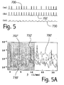
- Figs. 5 and 5A compare the spectra of the suction velocity for three rows of perforations, all having the same total or average mass flux.
- Fig. 5 shows a diagrammatic representation of the flow velocity amplitudes respectively for the three rows of perforations (a), (b) and (c).
- Row (a) with reference number 700 is a conventional hole geometry of 50 ⁇ m holes spaced 0.5 mm apart, with a 15% probability of clogging and a peak velocity of 1. In other words, the unclogged holes show a flow velocity of 1, while the clogged holes show no flow velocity, i.e. a flow velocity of 0.
- Row (b), with reference number 702 is a conventional hole geometry with the same holes as row (a) 700, but with 0 probability of clogging, i.e. without any of the holes being clogged.
- Row (c), with reference number 730 represents a row of micro-slots according to the present example of the invention, with no clogging and a peak velocity of 0.26 for each hole. Note that the larger size of the micro-slot in comparison to the conventional holes achieves the same total airflow mass flux with a lower peak velocity for each perforation.
- Fig. 5A is a graph showing the Fourier transform of the wavenumber ⁇ spectra of the flow profiles generated by the respective rows 700, 702 and 730, whereby the respective spectra are identified with reference numbers 700', 702', 730', respectively.
- the micro-slot spectrum 730' yields about a 3-fold reduction in amplitude at all wavenumbers in comparison to conventional geometry (b) 702'. This reduction is due to the lower peak velocity over the slots.
- the micro-slots offer a 30-50 fold reduction in amplitude at essentially all wavenumbers when compared to the conventional configuration (a) 700' which is more representative of actual conventional perforated plates with clogging.
- micro-slots greatly minimize the effect of boring and machining tolerances, and clogging.
- This is carried out by constructing a series of rows of micro-slots, referred to herein as a "bundle" 250, in such a way that the Fourier transformed total geometry of the overall bundle has essentially no resultant amplitude (e.g.
- the function is the Fourier transform of a series of rectangular pulses of width 2r, where 2r matches the width of a micro-slot.
- the resulting geometry for this example case is shown in Fig. 6 .
- This geometry is not unique, and depends to a large extent on the optimizer used to minimize ⁇ . What is unique, is the minimal energy of the geometry of one bundle 250 in the selected range of ⁇ . In this example, the chordwise extent of the bundle 250 is about 1.75 mm. Other widths are possible.
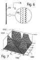
- the corresponding spectrum in the ⁇ r - ⁇ plane is shown in Fig. 7 .
- the dark line 1002 shows the ⁇ r - ⁇ combination, i.e. the dispersion relation, for the unstable modes at this x location (see Fig. 3 ). All along this line 1002 the amplitude of the spectral peaks 1010 and 1012 is very low, showing that essentially no CF modes are generated by the selected perforation pattern distribution.
- the unstable mode line 1002 passes through a "valley" in the spectral ridge or peak 1010.
- This "valley” is formed by purposeful destructive interference at this wavenumber combination by the proper design and selection of the pattern of the perforations, of which the individual spectral influences interfere with one another.
- the inventive goal of achieving essentially no energy or negligible energy at the pertinent selected wavelengths can thus be understood as meaning that, along the dispersion relation 1002 in Fourier space, there are no peaks of wavenumber amplitude with an amplitude value more than ten times (for example) the overall average amplitude of the spectral range spanning twice the unstable wavenumber range.
- reference numbers 1010 and 1012 identify components of the energetic wavelengths related to or resulting from the particular bundle geometry or pattern of perforations.
- the range 1000 of ⁇ values denotes the ⁇ values for which steady cross-flow modes are unstable at the location of the selected bundle, and the line 1002 particularly denotes the associated wave dispersion relation, for example according to Fig. 3 .
- the spatial spectrum of this bundle is essentially absent of energy (above a base "noise" level) at this selected or predetermined wavelength.
- predetermined wavelengths are chosen to match the wavelengths of predetermined flow instabilities appearing in the boundary layer above the respective bundle at cruise conditions.
- inventive destructive interference such that there is essentially no energy at the selected predetermined wavelengths of flow instabilities, the action of suction through the perforations will generate a minimum excitation of flow instabilities in the boundary layer stream above the perforated skin.
- the receptivity coefficient is a factor that couples the amplitude of the spatial spectrum of the surface suction distribution to the amplitude of the spatial spectrum of the disturbances in the boundary-layer airflow generated by the suction distribution.
- the simplicity of the above equation (2) stems from the assumption that the receptivity coefficient is constant over the chordwise extent of each individual bundle, but may vary from bundle to bundle. This approximation improves in validity as both the individual bundle width and the average suction strength become smaller.
- a further optimization of the perforation pattern within a bundle is carried out for each individual bundle using as a norm the disturbance flow field downstream of the bundle as given by solutions to the equations of motion, with the equations preferably in linearized form to simplify the computation.
- the optimized pattern will continue to have essentially negligible energy at the predetermined wavelengths.
- further optimization of the overall arrangement of plural bundles is possible by spanwise shifting of one or more respective bundles relative to each other to create further destructive interference between any remaining flow disturbances downstream of each bundle.
- the invention can use not only destructive interference among the flow conditions generated by the respective perforations of a given single bundle, but also destructive interference between any flow disturbances remaining downstream of a given bundle and the flow pattern of the successive downstream bundle or bundles.
- Fig. 6A The slot geometry for another embodiment of the invention, wherein the slots 201 are slanted to a predetermined angle relative to the local free-stream direction and at a selected oblique angle relative to the longitudinal direction of the bundle 250, is shown in Fig. 6A.
- Fig. 7A shows the associated spectrum, with the desired absence of energy in the range ⁇ 1 ⁇ ⁇ ⁇ ⁇ 2 .
- Slots oriented along or parallel to the free-stream direction offer the least "frontal area" to the oncoming flow, hence allow a higher level of suction before "oversuction" takes place.
- Slots oriented essentially normal to the potential-flow streamlines offer smaller wavelengths in the flow direction. Which of the two is preferable depends on the actual flow conditions.
- Fig. 10 displays an arrangement of several parallel bundles 250 at and near the leading edge 50, with each bundle having micro-slots oriented essentially normal to the local potential-flow streamline 60, such as the micro-slots shown at 202, 203, 204.
- the leading-edge region is most unstable to traveling waves (e.g. Gortler-Haemerlin modes)
- the spectrum of the leading-edge bundle is essentially absent of amplitude at spatial wavenumbers corresponding to these modes.
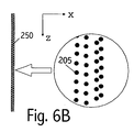
- Fig. 6B shows a pattern of circular holes 205, which could alternatively be used in a bundle 250, for achieving the desired destructive interference. It is thus the selected pattern and arrangement of the perforations in each bundle that is most significant. Nonetheless, since the small circular holes 205 will be more subject to clogging and machining errors as discussed above, the elongated micro-slot shape is preferred according to the invention.
- the suction flow is developed through the perforations by applying suction to a plenum under the perforated skin.
- the static pressure in the plenum below the perforated skin is not spatially uniform due to structural obstructions, standing waves, etc.
- an estimate of the wavelengths of this spatial inhomogeneity provides the value of ⁇ 1 and ⁇ 2 for the minimization range ⁇ 1 ⁇ ⁇ ⁇ ⁇ 2 .
- V wall ⁇ ⁇ ⁇ p 0 ⁇ hole ⁇ + 1 2 ⁇ ⁇ ⁇ p 1 ⁇ * hole ⁇ + ...
- the first term on the right hand side of the equation is the term that has been dealt with above.
- the second term leads to a spectral broadening of each Fourier mode of the geometry.
- the conventional pattern is a rectangular area 7 mm wide in the x direction and periodic in z in which 70 ⁇ m holes are spaced in a checkerboard pattern having 0.5 mm maximum distance between holes as shown at the top of Fig. 8 , with some holes clogged.
- the optimized bundle is the same as discussed above and is shown at the top of Fig. 9 .
- Both hole patterns have the same total open area, hence approximately equal mass flux for a given pressure differential, and essentially equal peak suction velocities.
- the boring and machining tolerances are 15 and 20 ⁇ m, respectively, and the conventional pattern has a random number of plugged holes not exceeding 10% of the total.
- Fig. 8 shows the geometry and the associated spatial spectrum for the conventional pattern
- Fig. 9 shows the same information for the inventive tuned bundle.
- the amplitude of the spectra has been scaled to better display the values in the unstable wavenumber range. Note that both plots have the same limits.
- Fig. 10 is a schematic perspective view of a portion of a leading edge area of an airfoil 40, such as a lifting wing, a control surface member, a stabilizer, a tailfin, or the like of an aircraft, as a representative aerodynamic body 40.
- an airfoil 40 such as a lifting wing, a control surface member, a stabilizer, a tailfin, or the like of an aircraft
- the airfoil 40 includes a perforated outer skin 100, which is particularly provided with linearly extending groups or bundles 250 of rows of perforations 200 according to the invention.
- the bundles 250 of perforations all extend longitudinally parallel to the leading edge 50, i.e. parallel to the spanwise direction z, and are spaced apart from one another in the chord direction x.
- respective non-perforated surface areas are provided between and separating adjacent ones of the perforation bundles 250 from each other.
- the pattern and parameters of the perforations e.g. the length, width, shape, spacing, orientation, periodicity, staggering, porosity (open perforation area relative to total area), number of rows, grouping of rows, and spacing of rows of the perforations in this bundle, are optimized in accordance with the principles of the invention discussed above.
- the pattern and parameters of the perforations of a given bundle are designed so that the bundle possesses a spatial spectrum that is essentially absent of energy (above the average "noise" energy level) at predetermined wavelengths such that the disturbances in the flow created by suction through the perforations cancel each other downstream of the bundle due to destructive interference of the flow disturbances at the predetermined wavelengths.
- the excitation energy of the spatial spectrum associated with the respective bundle can be minimized particularly at the most troublesome wavelengths, i.e. the wavelengths of predetermined flow instabilities that otherwise appear in the boundary layer above the bundle at cruise conditions of the aircraft comprising the subject airfoil 40.
- These wavelengths are particularly the wavelengths at which cross-flow modes of the boundary layer flow are unsteady at the chordwise location of the chosen bundle, for example as described by the respective associated dispersion relation, e.g. in connection with Fig. 3 .
- micro-slots 200 of a given bundle 250 are generally and preferably oriented with their long axes all parallel to each other, the micro-slots of different bundles can have different orientations.
- the incident airflow attaches along the leading edge 50, and the flow streamlines outside of the boundary layer (potential flow) that impinge on the airfoil 40 away from the leading edge 50 will develop a curved airflow path 60.
- advantages can be achieved by orienting the micro-slots 200 of a given bundle 250 so that the long axes of the micro-slots are essentially perpendicular to the local free-stream direction as indicated by the free steam line 60.
- the micro-slots 202 of a bundle 250 directly along the leading edge 50 are oriented substantially perpendicular to the lengthwise direction of this bundle and perpendicular to the local free stream flow, while the micro-slots 203 and 204 of bundles located successively farther away from the leading edge 50 are oriented at appropriate oblique angles relative to the lengthwise direction of extension of the given bundle 250 so that the respective micro-slots of the bundle are substantially perpendicular to the free-stream flow 60 at that chordwise location.
- the micro-slots could be arranged instead with their long axes essentially parallel to the local free-stream flow direction 60.
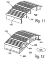
- the perforated skin 100 must be structurally supported by an underlying support structure, which in this case comprises longitudinal ribs 300 in structural union with, e.g. joined or connected with, the outer skin 100.
- the ribs 300 extend substantially parallel to the leading edge 50 of the airfoil 40, thus also parallel to the perforation bundles 250. Accordingly, it is a simple design consideration, to ensure that the longitudinal ribs 300 run along below the skin 100 at the unperforated areas between adjacent perforated bundles 250.
- the perforated outer skin 100 is structurally supported by the ribs 300, without the ribs 300 blocking any of the perforations 200 of the bundles 250, and without destroying or significantly influencing the particular designed flow properties of the designed spatial spectrum of each bundle.
- the flow properties of each bundle can be designed without consideration of the structural support needed by the airfoil, as long as the supporting ribs 300 are then arranged in the non-perforated skin areas between adjacent bundles 250.
- the skin 100 and the supporting ribs 300 can be joined to each other in any conventionally known suitable manner, for example by welding or by riveting of flanges.
- the outer skin 100 can be easily integrally manufactured with the supporting ribs 300, by a single extrusion thereof.
- the previously designed patterns of perforations making up the bundles 250 are then machined in any known manner into the extruded component.
- Fig. 12 schematically shows yet a further development of the total structure of the representative airfoil 40.
- the embodiment of Fig. 12 further includes an inner perforated member 400 such as a perforated inner plate 400 that is welded, riveted, bonded, or in any other structural union with the longitudinal ribs 300, to form respective air channels 420 between the outer skin 100 and the inner plate member 400.
- each channel 420 is bounded between the outer skin 100, the inner plate member 400, and respective adjacent ones of the ribs 300.
- This inner plate member 400 serves two important purposes.
- the inner plate member 400 together with the ribs 300 and the outer skin 100 form a strong rigid box beam construction with a high strength to weight ratio.
- the air channels 420 formed by providing the inner plate member 400 can be used to control the suction effect or suction flow provided to each respective group of perforation bundles 250 within a chordwise range of the airfoil defined by a respective one of the air channels 420 between adjacent ones of the supporting ribs 300.
- the suction flow is applied by any conventionally known suction generator 600, to a common plenum 500 under the plate member 400, and then is distributed as needed through the holes 450 of the plate member 400 to the individual channels 420, as will be discussed in further detail.
- the present invention can compensate for the streamwise pressure variation in three ways, which each use the property of independence of the respective bundles: first by changing the porosity of respective bundles in the streamwise direction, secondly by modifying the associated supporting structure and particularly the perforated inner plate member 400, and thirdly by a combination of the preceding two possibilities.
- the secondary perforations or holes 450 of the inner plate member 400 communicate between each air channel 420 and the single open plenum area 500 below the inner plate member 400.
- the width (i.e. chordwise extent) of each channel 420 is small enough between successive ribs 300 such that the external pressure variation over the width of any one channel 420 and associated group of bundles 250 is small.
- the suctioned boundary layer air flows through the perforations 200 in the outer skin 100, through the height of the respective communicating channel 420, and then through the secondary perforations 450 of the inner perforated plate member 400 to reach the internal air plenum 500 that is maintained at an essentially constant and uniform suction or vacuum pressure by the suction generator 600.
- the suction generator 600, plenum 500 and air channels 420 individually or collectively can be considered as forming a suction system.
- the inner perforated plate member 400 has a predetermined porosity provided by the secondary perforations 450, to achieve a selected throttling effect to control the suction pressure and suction flow through the associated channel 420.
- the predetermined porosity provided by the secondary perforations 450 of the inner plate member 400 is such that the total of the flow resistance offered by the primary perforations 200 of the outer skin 100 along this particular air channel 420 plus the flow resistance of the secondary perforations 450 through the inner plate member 400 at the area of this channel 420 yields the desired flow rate at the particular chordwise point of interest.
- the porosity of the inner plate varies from channel to channel precisely as required to counteract the external variations in pressure.
- the hole pattern of the secondary perforations 450 in the inner plate member 400 may be relatively freely chosen in comparison to the inventive patterns of the perforations 200 on the outer skin 100, because the inner plate member 400 is not subject to the flow conditions of the external boundary layer flow.
- the longitudinal ribs 300 preferably have a high thermal conductivity and will conduct heat from the inner plenum 500 to the outer skin 100. Also, warm air can be selectively blown into the inner plenum 500 to be blown out through the perforations 200 in the outer skin 100, to provide a heat flux to the outer skin 100, which can prevent or assist in the removal of ice build-up on the outer skin surface.
- This operation of the inventive structure is, of course, applicable at times when boundary layer control by means of suction is not required.
- each bundle 250 and the width of each channel 420 can vary or taper slowly in the spanwise length direction, to accommodate the slow spanwise change in potential and boundary layer flow quantities in weakly conical flows, such as those present along the tapered lifting surfaces, like wings, stabilizers, and fins of the aircraft.
- the present inventive structure including a perforated skin for influencing or controlling the boundary layer flow of a fluid along a surface is especially applicable to the outer skin of airfoil members, such as the lifting wings, stabilizers, fins, control surfaces, and air intake surfaces of an aircraft.
- the inventive structure is further applicable to any other situation involving a relatively high speed boundary layer flow of a fluid along a surface.
- the inventive perforation patterns are applicable to surfaces of wind tunnels for reducing or eliminating flow disturbances. Hydrodynamic applications are also possible.
Description
- This invention relates to an aerodynamic body with a perforated skin structure.
- From the document
US 2 833 492 a boundary layer control system is known, wherein the boundary layer of air flowing around an airfoil is controlled by holes in the airfoil surface and a suction system arranged in the airfoil. - Further in the document
US 6 068 328 a boundary layer control system is provided, wherein the surface of a vehicle is perforated with holes which are connected to a suction system, which is controlled by a microprocessor. It is generally known in the art that the laminar-flow conditions of the boundary layer of a fluid flowing over the surface of a body can be influenced by various devices. It is further known that stabilizing the laminar-flow conditions of the boundary layer can reduce the resulting skin friction between the fluid and the body. This is especially pertinent, for example, in the field of aircraft construction, whereby the improvement of the laminar-flow of the boundary layer and the resulting lower skin friction can achieve potential fuel savings in the operation of the aircraft. - For these reasons, the use of surface suction through a porous or perforated surface for stabilizing the laminar-flow boundary layer of the fluid flowing over, or relative to, the surface has been widely studied for many decades. In the context of commercial aircraft, known laminar-flow control devices generally must operate with the best efficiency at only one condition, namely the cruise flight condition, and are thus designed primarily for this operating condition.
- It has been preferred to apply surface suction through a purposely perforated surface, rather than a porous surface, due to the control of the surface characteristics that can be achieved by purposely forming the perforations, for example with desired sizes, patterns, and spacings. It is known to form such perforations by mechanical drilling, etching, electron beam boring, or laser beam boring. Typical conventional perforation designs provide perforations that are essentially small holes with circular plan or sectional shapes, with a diameter much smaller than the thickness of the boundary layer flowing over the surface. Typical diameters of the perforations or holes are conventionally in the range of 50 to 100 µm. Typical conventional spacings between adjacent perforations range from 200 to 5000 µm.
- According to the prior art, the holes or perforations are typically provided in patterns that are regular and spatially repeating or similar (e.g. essentially translationally invariant) over wide portions of the surface. Examples of such patterns are checkerboard patterns, or patterns of linear rows of holes with essentially equal hole-to-hole spacing along each row and essentially equal row-to-row separation. The perforation density is generally held constant, for machining convenience and the like, but advantages of spatially varying porosity have been discussed. For example,
U. S. Patent 5,263,667 (Horstman ) describes a rectilinear pattern of perforations with spatially varying perforation density, in an effort to achieve an essentially constant suction velocity in a region of varying external pressure. -
- All known perforation patterns described in the previous art are generic in the sense that they are not determined from, and do not reflect or contain, any information regarding the structure, form, flow conditions, or especially flow instabilities of the boundary layer that flows over the perforated surface. Since the abatement and elimination of such flow instabilities is a primary purpose of the laminar-flow control system, as recognized and developed by the present inventor, all previously existing or suggested perforation patterns of conventional surface suction systems yield either inefficient or dysfunctional laminar-flow control results. The basic reason for such inefficiency lies within the physics governing the boundary layer instabilities.
- As known by those skilled in the art, boundary layer flows developing over a swept wing, a swept vertical stabilizer, or a swept horizontal fin of an aircraft have three velocity components and are thus called three-dimensional (3-D) boundary layer flows. While the laminar-turbulent flow transition in two-dimensional boundary layers is dominated by traveling waves known as Tollmien-Schlichting waves (TS waves), the three-dimensional boundary layers are high unstable to steady cross-flow vortices (CF vortices), which dominate the laminar-turbulent flow transition process in the three-dimensional flow context.
- Experiments have shown that suction through a conventional perforation pattern in a 3-D boundary layer has two opposing effects, namely one of stabilization due to a change in the mean velocity profile, and one of destabilization due to the excitation of steady cross-flow vortices by variations and inhomogeneities in the suction distribution. In this regard see H. Bippes (1999), "Basic experiments on transition in 3D boundary-layers dominated by crossflow instability", Progress in Aerospace Sciences 35: 363-412 and D. Arnal, A. Seraudie, J.P. Archambaud, "Influence of surface roughness and of suction on the receptivity of a swept-wing boundary layer", Laminar-Turbulent Transition, IUTAM Symposium, Sedona AZ, Sept. 13-17, 1999, Springer, 2000. It has also been observed that there is a clear limit to the amount of suction that can be applied to 3-D boundary layers, beyond which the flow in the vicinity of each hole becomes sufficiently distorted to cause the flow to undergo an immediate and irrecoverable transition to turbulence. This effect is called "oversuction". In this regard, see P. Wassermann and M. Kloker, "DNS-investigations of the development and control of cross-flow vortices in a 3-D boundary-layer flow", Laminar-Turbulent Transition, IUTAM Symposium, Sedona AZ, Sep. 13-17, 1999, Springer, 2000.
- At any suction level, the hole pattern has a dominant influence on non-uniformities in the suction distribution. For values of suction strength below the "oversuction" level, the present inventor has previously described a formulation for determining the wavenumber components of the surface hole distribution that are most efficient in stimulating unstable boundary-layer modes. See F. P. Bertolotti (2000), "Receptivity of three-dimensional boundary-layers to localized wall roughness and suction", Phys. Fluids, Vol. 12, Number 7, pg. 1799-1809). In most conventional cases, the hole-to-hole spacing is smaller than the smallest wavelength of amplified disturbances. Theoretical results assuming a perfectly homogeneous wall-suction distribution in space show that both the TS waves and the CF vortices are strongly stabilized by suction, in contradiction to the above mentioned experimental findings. The cause has been traced to variations, or inhomogeneities, in the actual suction distribution in the experiments, as a result of various phenomena that introduce unwanted and harmful variations in the suction distribution pattern. Namely, it has now been considered by the present inventor, that the following phenomena introduce such unwanted and harmful variations in the suction distribution pattern.
- a) Unavoidable boring or machining inaccuracies and tolerances, to which the overall laminar-flow control efficiency is highly sensitive;
- b) Clogging of perforations by contamination or particulate matter during operation;
- c) Blockage of perforations by the structure supporting the perforated skin;
- d) Suction inhomogeneity within the internal suction chambers applying suction to the perforated skin;
- e) Chordwise variations in external pressure; and
- f) Flow distortions in the vicinity of a perforation due to large suction velocities.
- Among the above phenomena, the phenomena identified as a), b) and c) introduce variations in the perforation geometry, while d), e) and f) introduce variations in the suction strength and flow conditions. All of these phenomena produce harmful variations in the suction pattern. Furthermore, these phenomena can have interactive effects with one another. For example, when only a single suction plenum, or only a few suction plenums are used below the perforated skin, the phenomenon e) strongly affects the pressure-drop across the skin and may cause "oversuction" to occur at some locations, resulting in flow distortions according to phenomenon f).
- In view and in consideration of the above, the invention aims to achieve the following objects singly or in combination:
- to provide a perforation shape and a perforation distribution pattern for a laminar-flow control device employing suction, that overcomes harmful or disadvantageous effects of the following phenomena:
- a) Unavoidable boring or machining errors;
- b) Clogging of perforations;
- c) Blockage by the structure supporting the perforated skin;
- d) Suction inhomogeneity within the internal suction chambers; and
- e) Flow distortions in the vicinity of a perforation due to large suction velocities;
- to provide a perforated skin structure that compensates for chordwise external variations in external pressure;
- to provide a perforated skin structure that has structural rigidity, and avoids significant weakening effects of the perforations; and
- to provide a perforated skin structure that has high thermal conductivity.
- The invention further aims to avoid or overcome the disadvantages of the prior art, and to achieve additional advantages as apparent from the present description, claims, abstract, and drawings.
- The above objects have been achieved by the features of
claim 1 and, in particular, by a laminar flow control arrangement including a perforated skin constructed with numerous perforations arranged in a pattern having a spatial spectrum that is essentially absent of energy at predetermined wavelengths. The term "essentially absent of energy" must be understood in relation to the additional peak energy above the average background "noise" level of energy resulting from the unavoidable machining inaccuracies and the like. Preferably, these predetermined wavelengths are the wavelengths of predetermined flow instabilities, and especially the most unstable disturbances appearing in the boundary layer flowing over the perforated skin, particularly at the design operating conditions of the laminar-flow control arrangement, such as at the aircraft cruise flight conditions of the pertinent aircraft. - The preferred embodiment or mode of the inventive pattern and shape of perforations comprises a plurality of longitudinally extending perforated areas or groups of rows of perforations, which are spaced apart from each other, and which are called "bundles" herein. Most preferably, these longitudinally extending bundles are aligned essentially parallel, (e.g. within 10° of preferably 5° of parallel) to the leading edge of the surface provided with the perforations, for example the perforated skin of the airfoil. The term "essentially parallel"
- also allows for a slight convergence of the bundles relative to each other, from the root end to the tip end of the airfoil, for example following the taper of the airfoil. The bundles are separated laterally from one another by non-perforated areas.
- Each bundle comprises a plurality of perforations arranged to yield a spatial spectrum of each respective bundle that has reduced energy or is preferably essentially absent of energy (above a general or average "noise" energy level) at predetermined wavelengths. This is especially achieved by arranging the perforations of a given bundle so that the disturbances in the flow created by suction through the several perforations of the bundle mutually cancel each other out, or at least mutually destructively reduce each other, by destructive interference at these predetermined wavelengths. Preferably, these wavelengths are the wavelengths of the most unstable disturbances appearing in the boundary layer flowing over the perforated skin. Each perforation has the form of an elongated micro-slot having a width in the range of 50 to 250 µm and a length in the range of 100 to 3000 µm.
- According to a further embodiment feature of the invention, the laminar-flow control arrangement further includes a supporting structure that underlies and supports the perforated outer skin. The supporting structure is preferably in structural union with, e.g. joined or connected to, the outer perforated skin only at the non-perforated surface areas between the respective bundles of perforations. In a particular preferred embodiment, the supporting structure comprises longitudinal ribs running parallel to the adjacent bundles. In a further preferred feature of the invention, the supporting structure additionally comprises an inner perforated member such as a perforated inner plate member in structural union with the ribs below and spaced apart from the perforated outer skin, to form chambers respectively bounded by the perforated outer skin, adjacent pairs of the ribs, and the inner perforated member. The inner perforated member has second perforations that provide an inner surface with a predetermined and varying porosity to compensate for variations in external pressure and thereby to provide the desired suction rate through the perforated skin surface at all chordwise locations. Particularly, suction is applied to the side of the inner perforated member opposite the outer perforated skin, so as to apply suction to the chambers, which in turn applies suction to the primary perforations of the perforated outer skin. The inner perforated member and the outer perforated skin are each joined or connected with the ribs in any suitable manner, but preferably may be integrally formed, for example by integral extrusion.
- In order that the invention may be clearly understood, it will now be described in connection with example embodiments, with reference to the accompanying drawings, wherein:
- Fig. 1
- is a schematic perspective view of a portion of the leading edge of an airfoil embodied according to the invention, showing a coordinate system used for reference;
- Fig. 2
- is a stability diagram showing the spanwise wave number versus the arch length along the surface of the airfoil of a representative aircraft at cruise;
- Fig. 3
- is a diagram showing the wavenumber dispersion relations at selected chordwise locations in connection with the example of
Fig. 2 ; - Fig. 4
- is a schematic plan view showing a typical conventional perforation or hole having a round shape, as well as a typical micro-slot perforation according to the invention having an oblong shape;
- Fig. 5
- is a graphical representation of the velocity amplitudes of three example suction perforation arrangements, namely a single row of conventional holes in case (a) and case (b), and a single row of inventive micro-slots in case (c);
- Fig. 5A
- shows the Fourier transforms of the three suction perforation arrangements associated with
Fig. 5 ; - Fig. 6
- is a schematic plan view of one bundle or longitudinal stripe of several rows of micro-slots according to the invention, also shown in an enlarged view, with the long axis of the micro-slots aligned with the bundle longitudinal direction;
- Fig. 6A
- is a view similar to that of
Fig. 6 , but showing micro-slots with their long axes oriented at a predetermined non-parallel and non-perpendicular oblique angle relative to the bundle longitudinal direction; - Fig. 6B
- is a further view similar to that of
Figs. 6 and6A , but showing an arrangement of circular micro-holes arranged in a spatial pattern; - Fig. 7
- is a three-dimensional graphical representation of a double Fourier transform of the spectrum produced by a single bundle of micro-slots according to the invention as shown in
Fig. 6 ; - Fig. 7A
- is a graphical representation similar to that of
Fig. 7 , but showing the double Fourier transform of the spectrum produced by the single bundle of micro-slots oriented according toFig. 6A ; - Fig. 8
- is a three-dimensional graphical representation showing the spatial spectrum of a conventional suction hole pattern and distribution as shown in plan at the top of the figure;
- Fig. 9
- is a spectrum diagram generally corresponding to
Fig. 7A , for particular example perforation parameters, related to the inventive micro-slot perforation pattern shown in plan at the top of the figure; - Fig. 10
- is a schematic perspective view of a portion of the leading edge area of an airfoil of an aircraft having plural parallel spaced-apart bundles of micro-slots, whereby the micro-slots are arranged with different orientations at different chordwise locations, namely respectively arranged essentially perpendicularly to the local orientation of the potential flow streamline at each chordwise location, as shown in the enlarged detail views of the figure;
- Fig. 11
- is a schematic sectional view of a portion of an inventive airfoil arrangement including an outer perforated skin and a supporting structure including longitudinal ribs; and
- Fig. 12
- is a schematic sectioned perspective view similar to
Fig. 11 , but showing another embodiment of an airfoil structure according to the invention, further including a perforated inner plate member for pressure head compensation. - The invention will now be described in connection with an example relating to an airfoil, such as the vertical fin or the main lifting wing of an aircraft, which represent highly effective and preferred applications of the invention. As a reference for the following discussion,
Fig. 1 schematically shows the basic geometry of a representativeaerodynamic body 40 such as an airfoil portion of a lifting wing or the like of an aircraft. Theaerodynamic body 40 has anouter skin 100 and aleading edge 50. When thisaerodynamic body 40, or especially theairfoil 40, is moving through the air, the free-stream airflow impinges onto and grazes along theaerodynamic body 40, thereby creating a boundary layer airflow over theouter skin 100. Theaerodynamic body 40 and particularly its leadingedge 50 is positioned with a rearward sweep angle relative to the free-stream airflow direction, and consequently, the airflow attaches along the leadingedge 50 to form astreamline 62 of rectilinear form running parallel along the leading edge. - For reference,
Fig. 1 further shows a coordinate system with "z" identifying the direction along the leading edge (the spanwise direction), and "x" identifying the direction normal to the leading edge (chordwise direction). Due to the sweepback mentioned above, the flow streamlines of the airflow outside the boundary layer (potential flow) that impinge away from theattachment line 62 directly along the leadingedge 50 develop a curved flow path as shown by the curved dashedline 60. - Also represented in the flow pattern is an amplified cross-flow vortex, with wavenumber vector k oriented locally essentially perpendicular to the curved path of the
freestream flow line 60. This wavenumber vector k is composed of a component with wavenumber β in the spanwise direction z and a component with wavenumber αr in the chordwise direction x. For each value of β, the value of αr is given by a wave dispersion relation that can be experimentally or computationally determined in a conventionally known manner, for the respective flow condition at each respective chordwise location of a given airfoil. - Starting from these basic points and considerations in connection with
Fig. 1 , the underlying characteristic features of the invention will first be theoretically developed in the following discussion, and then specific concrete examples and applications thereof will be described. -
Figs. 2 and3 show the respective regions of stable and unstable spanwise wavelengths and wavenumbers for steady cross-flow (CF) vortices, as a function of chordwise location (i.e. arch length along the airfoil surface), for the case of flight of a representative example aircraft wing at cruising speed and altitude. The actual numerical values are only representative, and secondary in importance to the concepts and procedures to be described. Thus, more particularly,Fig. 2 shows the stability diagram for steady cross-flow disturbances as a function of spanwise wavenumber β of the flow with respect to chordwise locations x/c near the leadingedge 50. The wavelength, in millimeters, of the steady cross-flow modes of the flow is also shown. In this example, the spanwise wavenumber β of the steady cross-flow mode remains essentially constant as it propagates downstream, while the chordwise wave number αr thereof changes so that the wavenumber vector k remains essentially normal (within 5 to 10°) to the free-stream streamline 60 (seeFig. 1 ).Fig. 3 displays the dispersion relationships between β and αr at selected downstream locations. Together,Figs. 2 and3 present the wavenumber information needed for the construction of the present invention. - As generally discussed above, boring and machining inaccuracies or tolerances, as well as clogging of perforations, have a significant influence on the spectrum, i.e. the wavelength distribution of the suction flow conditions around the perforations. For the present demonstrative example to illustrate these effects, the following rather conservative tolerances are assumed: boring +/- 15 µm, and hole-center location +/- 20 µm. Additionally, based on an inspection of a perforated skin after use in both a wind tunnel and in an aircraft application, it was found that a large number of holes became clogged by particulate material and contaminants. For the present example, conservative clogging levels of 10 to 14% (i.e. 1-in-10 to 1-in-7 holes are clogged) are assumed.
- The presence of these machining tolerances, plus clogging, introduces variations in the suction distribution at all wavelengths. Since the energy at these wavelengths is proportional to the peak suction velocity through a hole or perforation, the simplest way to lower the detrimental effect of boring inaccuracies is to increase the overall porosity and thereby reduce the peak suction velocity for a given total suction air flow. With regard to clogging, the use of slots instead of round holes reduces the clogging problem, but elongated slits or slots having a substantial length are harmful and generally not acceptable, because they substantially reduce the stress-carrying ability of the outer skin.
- The invention overcomes the above problems by employing "micro-slits" or "micro-slots" 200 (see
Fig. 4 ). Theinventive micro-slots 200 have a generally oblong plan shape, with a length of about 250 µm and a width of about 70 µm in the present example. Generally, the size of the micro-slots according to the invention may comprise a length in the range of 100 to 3000 µm, more preferably with a practical maximum length of 500 µm, and a preferred maximum length of 200 to 300 µm, and a width in a range of 50 to 250 µm, and a preferred width at the lower end of that range, for example not more than 100, or not more than 80 µm. The overall porosity, i.e. the ratio of open hole area relative to total surface area is preferably up to about 10%, but practically preferably about 5%. In comparison to the prior art small circular holes, also shown inFig. 4 , themicro-slots 200 preferably used according to the invention offer a greater open area, and are thus well suited to providing somewhat higher porosity levels, while the elongated form also makes the micro-slots 200 significantly less likely to clog than the small round holes. On the other hand, the length of the micro-slots is limited to avoid the substantial reduction of the stress-carrying ability of the perforated outer skin that would arise with longer slots. - Further developing the present example, an optimized perforation pattern can be constructed by first considering a simple single linear row of
micro-slots 200, with the long axis of each micro-slot 200 aligned with the longitudinally extending row direction. Alternative patterns with the slots oriented at a predetermined angle to the local free-stream direction 60 are preferable near the leadingedge 50 of the aerodynamic body 40 (as will be discussed further below in connection withFigs. 6 and6A ) and in cases of high suction levels. In the present simplest example, the single micro-slot row has a separation of 400 µm between successive micro-slots, which thus yields a periodic pattern with a period of 650 µm (i.e. the 250 µm micro-slot length plus the 400 µm longitudinal spacing separation). This periodicity of the physical pattern of the perforations results in a particular spectral distribution of the physical pattern as well as of the flow disturbances generated thereby, as will be considered next. -
Figs. 5 and 5A compare the spectra of the suction velocity for three rows of perforations, all having the same total or average mass flux.Fig. 5 shows a diagrammatic representation of the flow velocity amplitudes respectively for the three rows of perforations (a), (b) and (c). Row (a) withreference number 700, is a conventional hole geometry of 50 µm holes spaced 0.5 mm apart, with a 15% probability of clogging and a peak velocity of 1. In other words, the unclogged holes show a flow velocity of 1, while the clogged holes show no flow velocity, i.e. a flow velocity of 0. Row (b), withreference number 702, is a conventional hole geometry with the same holes as row (a) 700, but with 0 probability of clogging, i.e. without any of the holes being clogged. Row (c), withreference number 730, represents a row of micro-slots according to the present example of the invention, with no clogging and a peak velocity of 0.26 for each hole. Note that the larger size of the micro-slot in comparison to the conventional holes achieves the same total airflow mass flux with a lower peak velocity for each perforation. These results were obtained by averaging 1000 configurations, each of which having randomly assigned values of clogging percentage and machining tolerances within their permitted range. -
Fig. 5A is a graph showing the Fourier transform of the wavenumber β spectra of the flow profiles generated by therespective rows - However, this reduction was achieved in the present example at the expense of introducing a large amplitude peak 732' (β = 9.66 1/mm) within the band of amplified unstable CF modes, denoted by the gray region in the figure. Due to this peak, a simple, or regular, arrangement of micro-slot rows would yield worse performance than the conventional pattern, which has its first large peak outside the amplified band. It is exactly such an undesirable peak 732' that can and will be "removed" or "canceled" by destructive interference according to the invention, as will be discussed below. Note that spacing the micro-slots closer together, say at 0.5 mm periods, would shift the amplitude peak 732' barely outside the amplified range. While this spacing is an option in this example (and the subsequent work applies this spacing, as well) there are other laminar-flow applications where this option is not available. To display the generality and great effectiveness of the inventive procedure and structure, the inventive high-performance pattern of perforations will now be developed with the chosen spacing.
- Using the fundamental idea of this invention, namely that the overall resultant spectrum of the total hole pattern must have essentially negligible energy (above the base "noise" level) at the wavenumbers of the unstable flow disturbances, the potentially harmful effect of the peak 732' at β+ = 9.66 1/mm will be eliminated by purposely introducing another flow disturbance by another row of micro-slots with a spectral component that will constructively interfere with the undesirable peak 732' at the relevant wavelength. This is carried out by constructing a series of rows of micro-slots, referred to herein as a "bundle" 250, in such a way that the Fourier transformed total geometry of the overall bundle has essentially no resultant amplitude (e.g. due to mutual destructive interference) at the streamwise wavenumbers αr † of the CF mode with β = β+ spanwise wavenumber. Note that if the most amplified mode was a traveling mode, then the αr corresponding to this mode would be selected. The present invention is not limited to steady cross-flow modes.
- Choosing x/c = 0.0076 for this example,
Fig. 3 shows that β† = 9.66 corresponds to αr † = 6.4 1/mm. Next, make abundle 250 of a small number N of micro-slot rows, say eight, in a general chordwise proximity, and take the precise streamwise location xn and phase in spanwise direction Φn (and optionally the width rn) of each row as the unknowns that minimize the square of the transform function:

in the range α1 < α < α2 centered about αr † of the CF mode with β = β†. The functionis the Fourier transform of a series of rectangular pulses of width 2r, where 2r matches the width of a micro-slot. The resulting geometry for this example case is shown in
Fig. 6 . This geometry is not unique, and depends to a large extent on the optimizer used to minimize ε. What is unique, is the minimal energy of the geometry of onebundle 250 in the selected range of α. In this example, the chordwise extent of thebundle 250 is about 1.75 mm. Other widths are possible. - The corresponding spectrum in the αr - β plane is shown in
Fig. 7 . The substantial (clipped)peaks Fig. 5A , now seen also in the α dimension. Thedark line 1002 shows the αr - β combination, i.e. the dispersion relation, for the unstable modes at this x location (seeFig. 3 ). All along thisline 1002 the amplitude of thespectral peaks unstable mode line 1002 passes through a "valley" in the spectral ridge orpeak 1010. This "valley" is formed by purposeful destructive interference at this wavenumber combination by the proper design and selection of the pattern of the perforations, of which the individual spectral influences interfere with one another. In this example, with reference toFigs. 5A and7 , the inventive goal of achieving essentially no energy or negligible energy at the pertinent selected wavelengths can thus be understood as meaning that, along thedispersion relation 1002 in Fourier space, there are no peaks of wavenumber amplitude with an amplitude value more than ten times (for example) the overall average amplitude of the spectral range spanning twice the unstable wavenumber range. Thus, inFig. 5A it can be seen that the peak 732' of higher unacceptable amplitude must be eliminated to achieve the inventive goal. More particularly,reference numbers range 1000 of β values denotes the β values for which steady cross-flow modes are unstable at the location of the selected bundle, and theline 1002 particularly denotes the associated wave dispersion relation, for example according toFig. 3 . As indicated by the dip in energy in thespectral component 1010 at the location at the intersection with thedispersion relation 1002, the spatial spectrum of this bundle is essentially absent of energy (above a base "noise" level) at this selected or predetermined wavelength. These predetermined wavelengths are chosen to match the wavelengths of predetermined flow instabilities appearing in the boundary layer above the respective bundle at cruise conditions. As a result of the inventive destructive interference, such that there is essentially no energy at the selected predetermined wavelengths of flow instabilities, the action of suction through the perforations will generate a minimum excitation of flow instabilities in the boundary layer stream above the perforated skin. - As is known to those skilled in the art, the receptivity coefficient is a factor that couples the amplitude of the spatial spectrum of the surface suction distribution to the amplitude of the spatial spectrum of the disturbances in the boundary-layer airflow generated by the suction distribution. The simplicity of the above equation (2) stems from the assumption that the receptivity coefficient is constant over the chordwise extent of each individual bundle, but may vary from bundle to bundle. This approximation improves in validity as both the individual bundle width and the average suction strength become smaller. In general, to further ensure that the absence of energy at predetermined wavelengths results from the destructive interference at these wavelengths between disturbances in the flow created by suction through the perforations, a further optimization of the perforation pattern within a bundle is carried out for each individual bundle using as a norm the disturbance flow field downstream of the bundle as given by solutions to the equations of motion, with the equations preferably in linearized form to simplify the computation. The optimized pattern will continue to have essentially negligible energy at the predetermined wavelengths. After each bundle is optimized by itself, further optimization of the overall arrangement of plural bundles is possible by spanwise shifting of one or more respective bundles relative to each other to create further destructive interference between any remaining flow disturbances downstream of each bundle. In other words, the invention can use not only destructive interference among the flow conditions generated by the respective perforations of a given single bundle, but also destructive interference between any flow disturbances remaining downstream of a given bundle and the flow pattern of the successive downstream bundle or bundles.
- The slot geometry for another embodiment of the invention, wherein the
slots 201 are slanted to a predetermined angle relative to the local free-stream direction and at a selected oblique angle relative to the longitudinal direction of thebundle 250, is shown inFig. 6A. Fig. 7A shows the associated spectrum, with the desired absence of energy in the range α1 < α < α2. Slots oriented along or parallel to the free-stream direction offer the least "frontal area" to the oncoming flow, hence allow a higher level of suction before "oversuction" takes place. Slots oriented essentially normal to the potential-flow streamlines offer smaller wavelengths in the flow direction. Which of the two is preferable depends on the actual flow conditions. At high Reynolds numbers, hence thin boundary layers, the latter is preferable. At lower Reynolds numbers, the former is preferable.Fig. 10 displays an arrangement of severalparallel bundles 250 at and near the leadingedge 50, with each bundle having micro-slots oriented essentially normal to the local potential-flow streamline 60, such as the micro-slots shown at 202, 203, 204. When the leading-edge region is most unstable to traveling waves (e.g. Gortler-Haemerlin modes), the spectrum of the leading-edge bundle is essentially absent of amplitude at spatial wavenumbers corresponding to these modes. - It should further be noted, in connection with
Fig. 6B , that the principle feature of the present invention, namely the mutual destructive interference among rows or groups of properly positioned perforations, can also be achieved with hole shapes other than elongated or oblong micro-slots. For example,Fig. 6B , shows a pattern ofcircular holes 205, which could alternatively be used in abundle 250, for achieving the desired destructive interference. It is thus the selected pattern and arrangement of the perforations in each bundle that is most significant. Nonetheless, since the smallcircular holes 205 will be more subject to clogging and machining errors as discussed above, the elongated micro-slot shape is preferred according to the invention. - The absence of amplitude in the range α1 < α < α2 makes neighboring
bundles 250 functionally substantially independent, so that adding a cloned bundle to either side of a given bundle will still yield and not destroy the minimizing property of either bundle. This is an important, and central, property of the bundles, and follows directly from the shift property of Fourier transforms. That is, letting x = 0 be the location of a first bundle, the contribution to the Fourier transform functionfrom a second bundle with similar range of minimized amplitudes (i.e. α1 < α < α2) and located Δx downstream from the first bundle is simply exp(-iαΔx) times the transform of the first bundle. Since the amplitude of this transform function is nearly zero in α1 < α < α2, the contribution to from the second bundle is nearly zero in this range of wavenumbers. Thus, the two bundles are functionally independent in the generation of CF modes.
- Furthermore, since the range in α of amplitude minimization changes smoothly and slowly in the chordwise direction in comparison with the width of a bundle, neighboring bundles will always share a large part of their minimized α range and will not interfere with one another. Consequently, it is possible, after designing the perforation pattern of the bundle, to simply lay down bundle after bundle at chosen locations to build a complete arrangement with a specified porosity.
- As will be discussed more concretely below, the suction flow is developed through the perforations by applying suction to a plenum under the perforated skin. The static pressure in the plenum below the perforated skin is not spatially uniform due to structural obstructions, standing waves, etc. As shown below, an estimate of the wavelengths of this spatial inhomogeneity provides the value of α1 and α2 for the minimization range α1 < α < α2.
- The suction velocity distribution Vwall(x,z) is proportional to the square-root of the pressure-drop, Δp(x,z), across the perforated panel times the hole geometry, hole(x,z). Since the bundle is narrow in x, variations in this direction can be neglected, and since the spatial variations in Δp are small in amplitude compare to the mean, the square-root is expanded in a series to obtain

- Each product corresponds to a convolution in wavenumber space,

- The first term on the right hand side of the equation is the term that has been dealt with above. The second term leads to a spectral broadening of each Fourier mode of the geometry. The more localized the variation Δp1(β) is in space, the larger the broadening. Assume that, for example, the variation of suction pressure has a very localized Gaussian distribution with a σ of five centimeters. Then Δp1(β) has significant amplitudes (i.e. above 2% of peak value) up to β = +/- 0.5 1/mm, causing a spectrum broadening of +/- 0.5 at the geometry peak of β = 9.66 in this example. Using
Fig. 3 to look up the corresponding change in αr, it turns out to be about +/- 0.4 1/mm at the chosen location x/c = 0.0076. Thus, the minimization in α must extend beyond +/- 0.4 of the central value, αr † = 6.4, to yield 6.0 < α < 7.2. InFig. 7 , the broadening about the CF mode αr - β relation (dark line 1002) would be a band extending along theline 1002. Note that the spectrum of the present optimized pattern is essentially zero over such a band along theline 1002, resulting in the desired insensitivity of the pattern to spatial variations in the plenum's pressure level. - Now the discussion will turn to a direct comparison between a conventional pattern and one optimized bundle. The conventional pattern is a rectangular area 7 mm wide in the x direction and periodic in z in which 70 µm holes are spaced in a checkerboard pattern having 0.5 mm maximum distance between holes as shown at the top of
Fig. 8 , with some holes clogged. The optimized bundle is the same as discussed above and is shown at the top ofFig. 9 . Both hole patterns have the same total open area, hence approximately equal mass flux for a given pressure differential, and essentially equal peak suction velocities. The boring and machining tolerances are 15 and 20 µm, respectively, and the conventional pattern has a random number of plugged holes not exceeding 10% of the total.Fig. 8 shows the geometry and the associated spatial spectrum for the conventional pattern, andFig. 9 shows the same information for the inventive tuned bundle. The amplitude of the spectra has been scaled to better display the values in the unstable wavenumber range. Note that both plots have the same limits. - It is clear from these two figures that the optimized inventive hole pattern of
Fig. 9 leads to much lower forcing in the unstable wavenumber range along theline 1002 at equal average mass-flux in comparison to the conventional pattern shown inFig. 8 , hence can be justly labeled a high-performance pattern. In consideration of the above discussion of the development of the preferred features of the invention, a concrete application example will now be discussed.Fig. 10 is a schematic perspective view of a portion of a leading edge area of anairfoil 40, such as a lifting wing, a control surface member, a stabilizer, a tailfin, or the like of an aircraft, as a representativeaerodynamic body 40. Theairfoil 40 includes a perforatedouter skin 100, which is particularly provided with linearly extending groups or bundles 250 of rows ofperforations 200 according to the invention. As can be seen, thebundles 250 of perforations all extend longitudinally parallel to the leadingedge 50, i.e. parallel to the spanwise direction z, and are spaced apart from one another in the chord direction x. Thus, respective non-perforated surface areas are provided between and separating adjacent ones of the perforation bundles 250 from each other. - In each
bundle 250, the pattern and parameters of the perforations, e.g. the length, width, shape, spacing, orientation, periodicity, staggering, porosity (open perforation area relative to total area), number of rows, grouping of rows, and spacing of rows of the perforations in this bundle, are optimized in accordance with the principles of the invention discussed above. Namely, the pattern and parameters of the perforations of a given bundle are designed so that the bundle possesses a spatial spectrum that is essentially absent of energy (above the average "noise" energy level) at predetermined wavelengths such that the disturbances in the flow created by suction through the perforations cancel each other downstream of the bundle due to destructive interference of the flow disturbances at the predetermined wavelengths. In this manner, the excitation energy of the spatial spectrum associated with the respective bundle can be minimized particularly at the most troublesome wavelengths, i.e. the wavelengths of predetermined flow instabilities that otherwise appear in the boundary layer above the bundle at cruise conditions of the aircraft comprising thesubject airfoil 40. These wavelengths are particularly the wavelengths at which cross-flow modes of the boundary layer flow are unsteady at the chordwise location of the chosen bundle, for example as described by the respective associated dispersion relation, e.g. in connection withFig. 3 . - While the
micro-slots 200 of a givenbundle 250 are generally and preferably oriented with their long axes all parallel to each other, the micro-slots of different bundles can have different orientations. As generally discussed above, due to the backswept extension of the leadingedge 50 of theairfoil 40, the incident airflow attaches along the leadingedge 50, and the flow streamlines outside of the boundary layer (potential flow) that impinge on theairfoil 40 away from the leadingedge 50 will develop acurved airflow path 60. As further discussed above, depending on the particular flow conditions of a given airfoil, advantages can be achieved by orienting themicro-slots 200 of a givenbundle 250 so that the long axes of the micro-slots are essentially perpendicular to the local free-stream direction as indicated by thefree steam line 60. - Thus, as shown in respective enlarged detail portions of
Fig. 10 , themicro-slots 202 of abundle 250 directly along the leadingedge 50 are oriented substantially perpendicular to the lengthwise direction of this bundle and perpendicular to the local free stream flow, while themicro-slots edge 50 are oriented at appropriate oblique angles relative to the lengthwise direction of extension of the givenbundle 250 so that the respective micro-slots of the bundle are substantially perpendicular to the free-stream flow 60 at that chordwise location. As discussed above as an alternative, to achieve different advantages in connection with different flow conditions, the micro-slots could be arranged instead with their long axes essentially parallel to the local free-stream flow direction 60. - The complete structure of the
airfoil 40 is further developed n connection withFig. 11 . As shown inFig. 11 , theperforated skin 100 must be structurally supported by an underlying support structure, which in this case compriseslongitudinal ribs 300 in structural union with, e.g. joined or connected with, theouter skin 100. Theribs 300 extend substantially parallel to the leadingedge 50 of theairfoil 40, thus also parallel to the perforation bundles 250. Accordingly, it is a simple design consideration, to ensure that thelongitudinal ribs 300 run along below theskin 100 at the unperforated areas between adjacentperforated bundles 250. Thereby, the perforatedouter skin 100 is structurally supported by theribs 300, without theribs 300 blocking any of theperforations 200 of thebundles 250, and without destroying or significantly influencing the particular designed flow properties of the designed spatial spectrum of each bundle. In other words, the flow properties of each bundle can be designed without consideration of the structural support needed by the airfoil, as long as the supportingribs 300 are then arranged in the non-perforated skin areas betweenadjacent bundles 250. This overcomes a significant problem of prior art arrangements, in which previously provided perforations are either blocked by the underlying support ribs, or the pattern of intended perforations must be interrupted, which of course destroys the intended flow characteristics achieved by the conventional hole patterns. - Furthermore, the
skin 100 and the supportingribs 300 can be joined to each other in any conventionally known suitable manner, for example by welding or by riveting of flanges. Preferably, however, theouter skin 100 can be easily integrally manufactured with the supportingribs 300, by a single extrusion thereof. The previously designed patterns of perforations making up thebundles 250 are then machined in any known manner into the extruded component. -
Fig. 12 schematically shows yet a further development of the total structure of therepresentative airfoil 40. In addition to the components shown and discussed in connection withFig. 11 , the embodiment ofFig. 12 further includes an innerperforated member 400 such as a perforatedinner plate 400 that is welded, riveted, bonded, or in any other structural union with thelongitudinal ribs 300, to formrespective air channels 420 between theouter skin 100 and theinner plate member 400. Particularly, eachchannel 420 is bounded between theouter skin 100, theinner plate member 400, and respective adjacent ones of theribs 300. Thisinner plate member 400 serves two important purposes. First, theinner plate member 400, together with theribs 300 and theouter skin 100 form a strong rigid box beam construction with a high strength to weight ratio. Secondly, theair channels 420 formed by providing theinner plate member 400 can be used to control the suction effect or suction flow provided to each respective group of perforation bundles 250 within a chordwise range of the airfoil defined by a respective one of theair channels 420 between adjacent ones of the supportingribs 300. The suction flow is applied by any conventionally knownsuction generator 600, to acommon plenum 500 under theplate member 400, and then is distributed as needed through theholes 450 of theplate member 400 to theindividual channels 420, as will be discussed in further detail. - As generally discussed above, oversuction problems of excessive suction flow velocities through particular perforations can be caused by the streamwise variation of the external pressure locally acting on the
airfoil 40. Thus, if a constant and uniform suction or vacuum pressure is applied to the entire underside of theperforated skin 100, then the pressure differential through any given perforation will depend on and vary with the external pressure. For simplicity and reliability, it is desirable to provide a single constant suction plenum pressure, but it is also advantageous to compensate for the streamwise variation of pressure differential, so as to achieve a controlled and intended suction mass flux for all of the perforations along the entire perforated areas of the skin. The present invention can compensate for the streamwise pressure variation in three ways, which each use the property of independence of the respective bundles: first by changing the porosity of respective bundles in the streamwise direction, secondly by modifying the associated supporting structure and particularly the perforatedinner plate member 400, and thirdly by a combination of the preceding two possibilities. - The secondary perforations or holes 450 of the
inner plate member 400 communicate between eachair channel 420 and the singleopen plenum area 500 below theinner plate member 400. The width (i.e. chordwise extent) of eachchannel 420 is small enough betweensuccessive ribs 300 such that the external pressure variation over the width of any onechannel 420 and associated group ofbundles 250 is small. The suctioned boundary layer air flows through theperforations 200 in theouter skin 100, through the height of the respective communicatingchannel 420, and then through thesecondary perforations 450 of the innerperforated plate member 400 to reach theinternal air plenum 500 that is maintained at an essentially constant and uniform suction or vacuum pressure by thesuction generator 600. Thesuction generator 600,plenum 500 andair channels 420, individually or collectively can be considered as forming a suction system. - In the area of each respective
individual channel 420, the innerperforated plate member 400 has a predetermined porosity provided by thesecondary perforations 450, to achieve a selected throttling effect to control the suction pressure and suction flow through the associatedchannel 420. Particularly, the predetermined porosity provided by thesecondary perforations 450 of theinner plate member 400 is such that the total of the flow resistance offered by theprimary perforations 200 of theouter skin 100 along thisparticular air channel 420 plus the flow resistance of thesecondary perforations 450 through theinner plate member 400 at the area of thischannel 420 yields the desired flow rate at the particular chordwise point of interest. Namely, the porosity of the inner plate varies from channel to channel precisely as required to counteract the external variations in pressure. The hole pattern of thesecondary perforations 450 in theinner plate member 400 may be relatively freely chosen in comparison to the inventive patterns of theperforations 200 on theouter skin 100, because theinner plate member 400 is not subject to the flow conditions of the external boundary layer flow. - Furthermore, the
longitudinal ribs 300 preferably have a high thermal conductivity and will conduct heat from theinner plenum 500 to theouter skin 100. Also, warm air can be selectively blown into theinner plenum 500 to be blown out through theperforations 200 in theouter skin 100, to provide a heat flux to theouter skin 100, which can prevent or assist in the removal of ice build-up on the outer skin surface. This operation of the inventive structure is, of course, applicable at times when boundary layer control by means of suction is not required. - It should also be noted that the width of each
bundle 250 and the width of eachchannel 420 can vary or taper slowly in the spanwise length direction, to accommodate the slow spanwise change in potential and boundary layer flow quantities in weakly conical flows, such as those present along the tapered lifting surfaces, like wings, stabilizers, and fins of the aircraft. - The present inventive structure including a perforated skin for influencing or controlling the boundary layer flow of a fluid along a surface is especially applicable to the outer skin of airfoil members, such as the lifting wings, stabilizers, fins, control surfaces, and air intake surfaces of an aircraft. The inventive structure is further applicable to any other situation involving a relatively high speed boundary layer flow of a fluid along a surface. For example, the inventive perforation patterns are applicable to surfaces of wind tunnels for reducing or eliminating flow disturbances. Hydrodynamic applications are also possible.
Claims (10)
- An aerodynamic body (40), comprising an outer skin (100) and a leading edge (50) defining a longitudinal direction (7), solid outer skin having a plurality of perforations (200; 201, 202, 203, 204) communicating therethrough, and having an outer surface adapted to be exposed to an airflow including a boundary layer airstream flowing along said outer surface; wherein flow disturbances are created in the boundary layer airstream due to the sucking of the air through said perforations (200; 201, 202, 203,204) by a suction system communicating with said perforations,
characterized in that said perforations (200; 201, 202, 203, 204) are spatially distributed in a spatial pattern of said perforations (200; 201, 202, 203, 204) which are respective micro-slots, wherein said spatial pattern comprises plural elongated longitudinally extending perforation bundles (250) which each include plural longitudinal rows (730) of said perforations (200; 201, 202, 203, 204), wherein said bundles (250) are arranged parallel to each other and spaced apart from one another with unperforated skin areas therebetween, and wherein said rows (730) of said perforations (200; 201, 202, 203, 204) are arranged to generate destructive interference of said flow disturbances relative to each other and said perforation bundles (250) are arranged to generate destructive interference of said flow disturbances relative to each other at least at one or more selected wavelengths. - The aerodynamic body (40) according to claim 1, characterized in that each one of said perforations (200; 201, 202, 203, 204) of a respective one of said bundles (250) is an elongated slot having a long axis oriented parallel to or perpendicular to or at an oblique angle to the longitudinal extension direction of said respective bundle (250).
- The aerodynamic body (40) according to claim 1 or 2, characterized in that said perforations (200; 201, 202, 203, 204) are elongated slots having long axes thereof oriented parallel to each other within each respective one of said bundles (250), and said slots of a first one of said bundles (250) are oriented with said long axes thereof in a different direction in comparison to said long axes of said slots of a second one of said bundles (250).
- The aerodynamic body (40) according to one of claims 1 to 3, characterized in that said slots of each respective one of said bundles (250) are oriented with said long axes thereof essentially perpendicular or parallel to a local flow direction of the boundary layer airstream flowing over said respective bundle (250).
- The aerodynamic body (40) according to one of claims 1 to 3, characterized in that a first one of said row groups within said respective bundle (250) has a different length, width, orientation, spacing, periodicity, staggering, number, or pattern of said perforations (200; 201, 202, 203, 204) in comparison to a second one of said row groups within said respective bundle (250).
- The aerodynamic body (40) according to any one of the preceding claims, characterized in that said one or more selected wavelengths correspond to flow wavelengths of predetermined unstable flow modes appearing in the boundary layer airstream at a particular chordwise location at which at least a selected portion of said spatial pattern of perforations (200; 201, 202, 203, 204) is located on said outer skin (100).
- The aerodynamic body (40) according to any one of the preceding claims, characterized in that said micro-slots have a length in a range of 100 to 3000 µm and a width in a range of 50 to 250 µm.
- The aerodynamic body (40) according to claim 7, characterized in that said length is not greater than 500 µm.
- The aerodynamic body (40) according to any one of the preceding claims, characterized in that said rows (730) are arranged parallel to each other in row groups of adjacent ones of said rows (730, 730) respectively having said perforations (200; 201, 202, 203, 204) staggered from one another, and with minor unperforated skin areas between adjacent ones of said row groups within each one of said bundles (250).
- The aerodynamic body (40) according to any one of the preceding claims, characterized in that said row groups in a respective one of said bundles (250) respectively include different numbers of said rows of said perforations (200; 201, 202, 203, 204).
Applications Claiming Priority (3)
| Application Number | Priority Date | Filing Date | Title |
|---|---|---|---|
| US37365302P | 2002-04-18 | 2002-04-18 | |
| US373653P | 2002-04-18 | ||
| PCT/US2003/012008 WO2003089295A2 (en) | 2002-04-18 | 2003-04-17 | Perforated skin structure for laminar-flow systems |
Publications (3)
| Publication Number | Publication Date |
|---|---|
| EP1578663A2 EP1578663A2 (en) | 2005-09-28 |
| EP1578663A4 EP1578663A4 (en) | 2010-11-24 |
| EP1578663B1 true EP1578663B1 (en) | 2013-06-05 |
Family
ID=29251057
Family Applications (1)
| Application Number | Title | Priority Date | Filing Date |
|---|---|---|---|
| EP03724090.0A Expired - Lifetime EP1578663B1 (en) | 2002-04-18 | 2003-04-17 | Perforated skin structure for laminar-flow systems |
Country Status (10)
| Country | Link |
|---|---|
| US (1) | US7152829B2 (en) |
| EP (1) | EP1578663B1 (en) |
| JP (2) | JP4268886B2 (en) |
| CN (1) | CN100408429C (en) |
| AU (1) | AU2003230975A1 (en) |
| BR (1) | BR0309313B1 (en) |
| CA (2) | CA2482247C (en) |
| RU (1) | RU2324625C2 (en) |
| UA (1) | UA89470C2 (en) |
| WO (1) | WO2003089295A2 (en) |
Families Citing this family (60)
| Publication number | Priority date | Publication date | Assignee | Title |
|---|---|---|---|---|
| DE10024624A1 (en) * | 2000-05-18 | 2001-11-22 | Bayer Ag | Modified polyisocyanates, e.g. useful in coating compositions, obtained by reacting polyisocyanates with 2-(cyclohexylamino)ethanesulfonic acid and/or 3-(cyclohexylamino)propanesulfonic acid |
| DK1749740T3 (en) | 2005-08-02 | 2011-05-02 | Univ Stuttgart | Flow surface for a three-dimensional boundary layer flow; especially on an arrow-shaped wing, an arrow-shaped tail plane or a rotor |
| US7291815B2 (en) | 2006-02-24 | 2007-11-06 | Goodrich Corporation | Composite ice protection heater and method of producing same |
| US7923668B2 (en) * | 2006-02-24 | 2011-04-12 | Rohr, Inc. | Acoustic nacelle inlet lip having composite construction and an integral electric ice protection heater disposed therein |
| EP2363429A1 (en) | 2006-03-10 | 2011-09-07 | Goodrich Corporation | Low density lightining strike protection for use in airplanes |
| WO2007130979A2 (en) | 2006-05-02 | 2007-11-15 | Rohr, Inc. | Modification of reinforcing fiber tows used in composite materials by using nanoreinforcements |
| DE102006049616B4 (en) * | 2006-10-20 | 2010-08-05 | Deutsches Zentrum für Luft- und Raumfahrt e.V. | Arrangement of an aerodynamic component with a slotted rear or side edge in a flow |
| US20080166563A1 (en) * | 2007-01-04 | 2008-07-10 | Goodrich Corporation | Electrothermal heater made from thermally conducting electrically insulating polymer material |
| US7850126B2 (en) * | 2007-04-25 | 2010-12-14 | The Boeing Company | Laminar flow surfaces with selected roughness distributions, and associated methods |
| US7866609B2 (en) * | 2007-06-15 | 2011-01-11 | The Boeing Company | Passive removal of suction air for laminar flow control, and associated systems and methods |
| US20090002463A1 (en) * | 2007-06-29 | 2009-01-01 | Jinquan Xu | Perforated fluid flow device for printing system |
| WO2011149440A2 (en) * | 2007-08-02 | 2011-12-01 | Sinhatech | Method for enhancing flow drag reduction and lift generation with a deturbulator |
| US20100236637A1 (en) * | 2007-10-05 | 2010-09-23 | Hendrix Jr James Edward | Surface Ventilator For A Compliant-Surface Flow-Control Device |
| US20090210103A1 (en) * | 2007-12-03 | 2009-08-20 | Mr. Michael Cook | Controlling aircraft aerial movements, defeating icing on aircraft surfaces, aiding decontamination, and damping turbulence effects on aircraft by the method of micro-perforated airfoil coordinated precision flow management |
| US7837150B2 (en) * | 2007-12-21 | 2010-11-23 | Rohr, Inc. | Ice protection system for a multi-segment aircraft component |
| GB2467130B (en) * | 2009-01-22 | 2012-11-28 | Cav Advanced Technologies Ltd | Method for perforating material |
| CN101602404B (en) * | 2009-07-03 | 2013-12-25 | 朱晓义 | Aircraft with novel structure |
| US8870124B2 (en) * | 2009-07-10 | 2014-10-28 | Peter Ireland | Application of elastomeric vortex generators |
| US8561934B2 (en) | 2009-08-28 | 2013-10-22 | Teresa M. Kruckenberg | Lightning strike protection |
| DE102009043489A1 (en) * | 2009-09-30 | 2011-03-31 | Airbus Operations Gmbh | Device for boundary layer extraction and composite component therefor |
| DE102009049049A1 (en) * | 2009-10-12 | 2011-04-14 | Airbus Operations Gmbh | Flow body especially for aircraft |
| GB0919110D0 (en) * | 2009-11-02 | 2009-12-16 | Rolls Royce Plc | A boundary layer energiser |
| US8783624B2 (en) * | 2010-08-15 | 2014-07-22 | The Boeing Company | Laminar flow panel |
| US10556670B2 (en) | 2010-08-15 | 2020-02-11 | The Boeing Company | Laminar flow panel |
| US8974177B2 (en) * | 2010-09-28 | 2015-03-10 | United Technologies Corporation | Nacelle with porous surfaces |
| CN102167162A (en) * | 2011-03-10 | 2011-08-31 | 洪瑞庆 | Ultra-high pressure fluid jetting power track transferring system and method for aircraft |
| US8919127B2 (en) | 2011-05-24 | 2014-12-30 | General Electric Company | System and method for flow control in gas turbine engine |
| EP2644496B1 (en) * | 2012-03-29 | 2015-07-01 | Airbus Operations GmbH | Surface element for an aircraft, aircraft and method for improving high-lift generation on a surface element |
| EP2644497B1 (en) * | 2012-03-29 | 2016-01-20 | Airbus Operations GmbH | Wing for an aircraft, aircraft and method for reducing aerodynamic drag and improving maximum lift |
| WO2014120328A2 (en) * | 2012-11-19 | 2014-08-07 | The Regents Of The University Of California | Hypersonic laminar flow control |
| US9487288B2 (en) * | 2013-06-04 | 2016-11-08 | The Boeing Company | Apparatus and methods for extending hybrid laminar flow control |
| DE102013111175B3 (en) * | 2013-10-09 | 2014-09-04 | Dr. Schneider Kunststoffwerke Gmbh | Air outlet for air conditioning apparatus, has lying chambers for first terminal and second terminal, which are opened for supplying or discharging air for generating overpressure and low pressure respectively |
| US10072511B2 (en) * | 2014-10-02 | 2018-09-11 | Rolls-Royce North American Technologies Inc. | Engine nacelle |
| US10337170B2 (en) | 2014-11-05 | 2019-07-02 | Volvo Construction Equipment Ab | Driving straight ahead device for construction machine and control method therefor |
| CN104386236A (en) | 2014-11-17 | 2015-03-04 | 朱晓义 | Aircraft with great lift force |
| US10000293B2 (en) | 2015-01-23 | 2018-06-19 | General Electric Company | Gas-electric propulsion system for an aircraft |
| US9932481B2 (en) * | 2015-04-21 | 2018-04-03 | The Boeing Company | Actuatable microstructures and methods of making the same |
| US9482096B1 (en) * | 2015-04-28 | 2016-11-01 | The Boeing Company | Textured leading edge for aerospace and nautical structures |
| GB201508545D0 (en) * | 2015-05-19 | 2015-07-01 | Rolls Royce Plc | Compressor tip injector |
| FR3037318B1 (en) * | 2015-06-15 | 2017-06-30 | Snecma | AIRCRAFT PROPULSIVE ASSEMBLY COMPRISING A NON-CARBONATED BLOWER TURBOREACTOR AND A PENSION PYLON |
| US10279899B2 (en) * | 2015-07-02 | 2019-05-07 | Blr Aerospace L.L.C. | Helicopter with anti-torque system, related kit and methods |
| US20170198988A1 (en) * | 2016-01-13 | 2017-07-13 | Hamilton Sundstrand Corporation | Vanes for heat exchangers |
| GB2556110B (en) * | 2016-11-21 | 2020-04-01 | Dyson Technology Ltd | Compressor blade surface patterning |
| GB2557341A (en) | 2016-12-07 | 2018-06-20 | Airbus Operations Ltd | Aircraft wing assembly |
| RU2657592C1 (en) * | 2017-03-23 | 2018-06-14 | Юрий Петрович Андреев | Method for producing the driving force of an aircraft |
| WO2018196810A1 (en) | 2017-04-26 | 2018-11-01 | 朱晓义 | Aircraft gaining greater propulsion and lift from fluid continuity |
| CN107150788A (en) * | 2017-04-26 | 2017-09-12 | 朱晓义 | A kind of Fixed Wing AirVehicle for producing greater lift |
| CN107089327A (en) * | 2017-04-26 | 2017-08-25 | 朱晓义 | A kind of aircraft for producing greater lift |
| GB2561880A (en) * | 2017-04-27 | 2018-10-31 | Airbus Operations Ltd | Aerodynamic body |
| CN106949120A (en) * | 2017-05-05 | 2017-07-14 | 吉林大学 | A kind of bionical Anti-erosion pipeline |
| EP3428062A1 (en) * | 2017-07-11 | 2019-01-16 | Airbus Operations GmbH | A leading edge structure for a flow control system of an aircraft |
| CN111683869B (en) | 2017-12-22 | 2023-11-10 | 迈克尔·奥凯利 | Viscosity reducing cladding |
| GB2571542A (en) | 2018-02-28 | 2019-09-04 | Airbus Operations Ltd | Apparatus and method for heating an aircraft structure |
| WO2020041509A1 (en) | 2018-08-24 | 2020-02-27 | Quest Engines, LLC | Controlled turbulence system |
| GB2581974A (en) * | 2019-03-05 | 2020-09-09 | Airbus Operations Ltd | Aerofoil leading edge structures |
| CN110481761B (en) * | 2019-08-20 | 2021-07-13 | 空气动力学国家重点实验室 | Flow transition passive control device utilizing surface opening/groove |
| GB2588830A (en) | 2019-11-11 | 2021-05-12 | Airbus Operations Ltd | Active drag control system for an aircraft |
| CN112208748B (en) * | 2020-10-13 | 2022-10-11 | 中国人民解放军国防科技大学 | Active and passive combination ultrahigh-speed boundary layer transition broadband control method |
| CN113483983B (en) * | 2021-09-08 | 2021-11-16 | 中国空气动力研究与发展中心高速空气动力研究所 | Hole wall transverse flow characteristic measuring device and measuring method thereof |
| CN115783233B (en) * | 2023-02-09 | 2023-04-21 | 中国空气动力研究与发展中心计算空气动力研究所 | Combined transition control device based on corrugated wall and boundary layer suction |
Family Cites Families (22)
| Publication number | Priority date | Publication date | Assignee | Title |
|---|---|---|---|---|
| US2646945A (en) * | 1950-09-05 | 1953-07-28 | John A Perry | Airplane wing structure |
| US2742247A (en) * | 1950-10-31 | 1956-04-17 | Handley Page Ltd | Outer surfaces for craft moving in one fluid |
| US2833492A (en) * | 1955-02-07 | 1958-05-06 | Harlan D Fowler | Boundary layer control system with aerodynamic glove |
| US3203648A (en) * | 1961-12-26 | 1965-08-31 | Northrop Corp | Means for removing boundary layer air from aircraft |
| US3261576A (en) * | 1962-06-14 | 1966-07-19 | Olin Mathieson | Aircraft structure |
| GB1125121A (en) * | 1964-10-20 | 1968-08-28 | Joseph Brian Edwards | Improvements in or relating to aircraft aerodynamic structures |
| DE1268979B (en) * | 1966-07-01 | 1968-05-22 | Hermann Papst | Overflowing wall, especially in aircraft, with slots for suction of the boundary layer |
| FR2235832B1 (en) * | 1973-07-05 | 1976-09-17 | Anxionnaz Rene | |
| JP2741224B2 (en) * | 1988-12-16 | 1998-04-15 | 泰昭 小濱 | Suction device for boundary layer control |
| US5141182A (en) * | 1990-06-01 | 1992-08-25 | General Electric Company | Gas turbine engine fan duct base pressure drag reduction |
| US5263667A (en) | 1991-09-09 | 1993-11-23 | The Boeing Company | Perforated wing panel with variable porosity |
| JPH06191491A (en) | 1992-07-06 | 1994-07-12 | Rockwell Internatl Corp | System for establishing pressure spreading area on surface of panel with hole of type formed for use in control of laminar air flow |
| GB9400577D0 (en) * | 1994-01-13 | 1994-03-09 | Britsh Aerospace Public Limite | Forming of structures |
| CN1138967C (en) | 1995-07-19 | 2004-02-18 | 尼古劳斯·维达 | Method and apparatus for controlling boundary or wall layer of continuous medium |
| DE19617952C2 (en) | 1996-05-04 | 1998-07-02 | Daimler Benz Aerospace Airbus | Suction generator system of an aircraft for the laminar maintenance of the boundary layer |
| DE19643069C2 (en) | 1996-10-18 | 1999-03-25 | Daimler Benz Aerospace Airbus | Vertical tail structure for an aircraft |
| DE19649132C2 (en) | 1996-11-27 | 1999-09-02 | Daimler Chrysler Aerospace | Nose for an aerodynamic surface and method of making it |
| US6068328A (en) * | 1997-11-25 | 2000-05-30 | Gazdzinski; Robert F. | Vehicular boundary layer control system and method |
| DE19820097C2 (en) | 1998-05-06 | 2003-02-13 | Airbus Gmbh | Arrangement for boundary layer suction and impact boundary layer control for an aircraft |
| DE10005348B4 (en) | 2000-02-08 | 2004-05-06 | Airbus Deutschland Gmbh | Process for the manufacture of nose structures for aerodynamic surfaces |
| US6332593B1 (en) | 2000-02-16 | 2001-12-25 | Brown University Research Foundation | Method and apparatus for reducing turbulent drag |
| US6866233B2 (en) * | 2003-01-03 | 2005-03-15 | Orbital Research Inc. | Reconfigurable porous technology for fluid flow control and method of controlling flow |
-
2003
- 2003-04-17 BR BRPI0309313-1A patent/BR0309313B1/en not_active IP Right Cessation
- 2003-04-17 JP JP2003586022A patent/JP4268886B2/en not_active Expired - Fee Related
- 2003-04-17 CA CA2482247A patent/CA2482247C/en not_active Expired - Fee Related
- 2003-04-17 RU RU2004133680/11A patent/RU2324625C2/en not_active IP Right Cessation
- 2003-04-17 EP EP03724090.0A patent/EP1578663B1/en not_active Expired - Lifetime
- 2003-04-17 CA CA2661810A patent/CA2661810C/en not_active Expired - Fee Related
- 2003-04-17 UA UA20041109439A patent/UA89470C2/en unknown
- 2003-04-17 AU AU2003230975A patent/AU2003230975A1/en not_active Abandoned
- 2003-04-17 US US10/511,930 patent/US7152829B2/en not_active Expired - Lifetime
- 2003-04-17 WO PCT/US2003/012008 patent/WO2003089295A2/en active Application Filing
- 2003-04-17 CN CNB038086026A patent/CN100408429C/en not_active Expired - Fee Related
-
2008
- 2008-12-26 JP JP2008333212A patent/JP2009102007A/en active Pending
Also Published As
| Publication number | Publication date |
|---|---|
| CA2661810A1 (en) | 2003-10-30 |
| CA2482247A1 (en) | 2003-10-30 |
| CN100408429C (en) | 2008-08-06 |
| JP4268886B2 (en) | 2009-05-27 |
| WO2003089295A2 (en) | 2003-10-30 |
| JP2005532209A (en) | 2005-10-27 |
| AU2003230975A1 (en) | 2003-11-03 |
| CN1812911A (en) | 2006-08-02 |
| EP1578663A4 (en) | 2010-11-24 |
| RU2004133680A (en) | 2005-04-20 |
| JP2009102007A (en) | 2009-05-14 |
| US20050178924A1 (en) | 2005-08-18 |
| CA2661810C (en) | 2011-05-31 |
| BR0309313B1 (en) | 2012-12-11 |
| BR0309313A (en) | 2007-02-21 |
| UA89470C2 (en) | 2010-02-10 |
| WO2003089295A3 (en) | 2005-09-15 |
| CA2482247C (en) | 2010-11-09 |
| AU2003230975A8 (en) | 2003-11-03 |
| US7152829B2 (en) | 2006-12-26 |
| RU2324625C2 (en) | 2008-05-20 |
| EP1578663A2 (en) | 2005-09-28 |
Similar Documents
| Publication | Publication Date | Title |
|---|---|---|
| EP1578663B1 (en) | Perforated skin structure for laminar-flow systems | |
| Woszidlo et al. | Parametric study of sweeping jet actuators for separation control | |
| US9132909B1 (en) | Flap edge noise reduction fins | |
| US7735782B2 (en) | Flow surface for a three-dimensional boundary-layer flow, especially on a swept wing, a swept tail plane or a rotor | |
| EP0273850A2 (en) | Bodies with reduced base drag | |
| US7537182B2 (en) | Simultaneous multiple-location separation control | |
| Margalit et al. | Delta wing stall and roll control using segmented piezoelectric fluidic actuators | |
| EP0273851A2 (en) | Gas turbine engine airfoil | |
| JPH01122784A (en) | Body with non-streamline type base section and overland car | |
| Greenblatt et al. | Delta-wing flow control using dielectric barrier discharge actuators | |
| US20100194144A1 (en) | Deturbulator fuel economy enhancement for trucks | |
| Desalvo et al. | High-lift enhancement using active flow control | |
| US20060060722A1 (en) | Controlling bondary layer fluid flow | |
| Wahidi et al. | Effects of distributed suction on an airfoil at low Reynolds number | |
| Abdolahipour et al. | Pressure improvement on a supercritical high-lift wing using simple and modulated pulse jet vortex generator | |
| DeSalvo et al. | High-lift performance enhancement using active flow control | |
| US6471157B1 (en) | Device and method for reducing aircraft noise | |
| DeSalvo et al. | High-lift enhancement using fluidic actuation | |
| JP7465483B2 (en) | Raised structures and objects | |
| Jafroudi et al. | Heat transfer enhancement through a rectangular channel by DBD plasma actuators as vortex generators | |
| Scholz et al. | Active control of leading edge separation within the german flow control network | |
| DeSalvo et al. | Enhancement of a high-lift airfoil using low-power fluidic actuators | |
| Ashill et al. | A review of flow control research at DERA | |
| Voevodin et al. | Wing Buffet Control by Using an Ejector-Type Device | |
| Bertolotti | The equivalent forcing model for receptivity analysis with application to the construction of a high-performance skin perforation pattern for LFC |
Legal Events
| Date | Code | Title | Description |
|---|---|---|---|
| PUAI | Public reference made under article 153(3) epc to a published international application that has entered the european phase |
Free format text: ORIGINAL CODE: 0009012 |
|
| PUAK | Availability of information related to the publication of the international search report |
Free format text: ORIGINAL CODE: 0009015 |
|
| AK | Designated contracting states |
Kind code of ref document: A2 Designated state(s): AT BE BG CH CY CZ DE DK EE ES FI FR GB GR HU IE IT LI LU MC NL PT RO SE SI SK TR |
|
| AK | Designated contracting states |
Kind code of ref document: A3 Designated state(s): AT BE BG CH CY CZ DE DK EE ES FI FR GB GR HU IE IT LI LU MC NL PT RO SE SI SK TR |
|
| RIC1 | Information provided on ipc code assigned before grant |
Ipc: 7B 64C 21/06 A |
|
| 17P | Request for examination filed |
Effective date: 20060315 |
|
| RBV | Designated contracting states (corrected) |
Designated state(s): AT BE BG CH CY CZ DE DK EE ES FI FR GB GR HU IE IT LI LU MC NL PT RO SE SI SK TR |
|
| A4 | Supplementary search report drawn up and despatched |
Effective date: 20101021 |
|
| 17Q | First examination report despatched |
Effective date: 20110406 |
|
| GRAP | Despatch of communication of intention to grant a patent |
Free format text: ORIGINAL CODE: EPIDOSNIGR1 |
|
| GRAS | Grant fee paid |
Free format text: ORIGINAL CODE: EPIDOSNIGR3 |
|
| GRAL | Information related to payment of fee for publishing/printing deleted |
Free format text: ORIGINAL CODE: EPIDOSDIGR3 |
|
| GRAS | Grant fee paid |
Free format text: ORIGINAL CODE: EPIDOSNIGR3 |
|
| GRAA | (expected) grant |
Free format text: ORIGINAL CODE: 0009210 |
|
| RAP1 | Party data changed (applicant data changed or rights of an application transferred) |
Owner name: AIRBUS OPERATIONS GMBH |
|
| AK | Designated contracting states |
Kind code of ref document: B1 Designated state(s): AT BE BG CH CY CZ DE DK EE ES FI FR GB GR HU IE IT LI LU MC NL PT RO SE SI SK TR |
|
| REG | Reference to a national code |
Ref country code: GB Ref legal event code: FG4D |
|
| REG | Reference to a national code |
Ref country code: CH Ref legal event code: EP |
|
| REG | Reference to a national code |
Ref country code: AT Ref legal event code: REF Ref document number: 615515 Country of ref document: AT Kind code of ref document: T Effective date: 20130615 |
|
| REG | Reference to a national code |
Ref country code: IE Ref legal event code: FG4D |
|
| REG | Reference to a national code |
Ref country code: DE Ref legal event code: R096 Ref document number: 60344218 Country of ref document: DE Effective date: 20130801 |
|
| REG | Reference to a national code |
Ref country code: DE Ref legal event code: R082 Ref document number: 60344218 Country of ref document: DE Representative=s name: UEXKUELL & STOLBERG, DE Ref country code: DE Ref legal event code: R082 Ref document number: 60344218 Country of ref document: DE Representative=s name: UEXKUELL & STOLBERG PARTNERSCHAFT VON PATENT- , DE Ref country code: DE Ref legal event code: R082 Ref document number: 60344218 Country of ref document: DE Representative=s name: BIRD & BIRD LLP, DE |
|
| REG | Reference to a national code |
Ref country code: AT Ref legal event code: MK05 Ref document number: 615515 Country of ref document: AT Kind code of ref document: T Effective date: 20130605 |
|
| PG25 | Lapsed in a contracting state [announced via postgrant information from national office to epo] |
Ref country code: AT Free format text: LAPSE BECAUSE OF FAILURE TO SUBMIT A TRANSLATION OF THE DESCRIPTION OR TO PAY THE FEE WITHIN THE PRESCRIBED TIME-LIMIT Effective date: 20130605 Ref country code: GR Free format text: LAPSE BECAUSE OF FAILURE TO SUBMIT A TRANSLATION OF THE DESCRIPTION OR TO PAY THE FEE WITHIN THE PRESCRIBED TIME-LIMIT Effective date: 20130906 Ref country code: ES Free format text: LAPSE BECAUSE OF FAILURE TO SUBMIT A TRANSLATION OF THE DESCRIPTION OR TO PAY THE FEE WITHIN THE PRESCRIBED TIME-LIMIT Effective date: 20130916 Ref country code: SE Free format text: LAPSE BECAUSE OF FAILURE TO SUBMIT A TRANSLATION OF THE DESCRIPTION OR TO PAY THE FEE WITHIN THE PRESCRIBED TIME-LIMIT Effective date: 20130605 Ref country code: SI Free format text: LAPSE BECAUSE OF FAILURE TO SUBMIT A TRANSLATION OF THE DESCRIPTION OR TO PAY THE FEE WITHIN THE PRESCRIBED TIME-LIMIT Effective date: 20130605 Ref country code: FI Free format text: LAPSE BECAUSE OF FAILURE TO SUBMIT A TRANSLATION OF THE DESCRIPTION OR TO PAY THE FEE WITHIN THE PRESCRIBED TIME-LIMIT Effective date: 20130605 |
|
| REG | Reference to a national code |
Ref country code: NL Ref legal event code: VDEP Effective date: 20130605 |
|
| PG25 | Lapsed in a contracting state [announced via postgrant information from national office to epo] |
Ref country code: BG Free format text: LAPSE BECAUSE OF FAILURE TO SUBMIT A TRANSLATION OF THE DESCRIPTION OR TO PAY THE FEE WITHIN THE PRESCRIBED TIME-LIMIT Effective date: 20130905 |
|
| PG25 | Lapsed in a contracting state [announced via postgrant information from national office to epo] |
Ref country code: SK Free format text: LAPSE BECAUSE OF FAILURE TO SUBMIT A TRANSLATION OF THE DESCRIPTION OR TO PAY THE FEE WITHIN THE PRESCRIBED TIME-LIMIT Effective date: 20130605 Ref country code: CZ Free format text: LAPSE BECAUSE OF FAILURE TO SUBMIT A TRANSLATION OF THE DESCRIPTION OR TO PAY THE FEE WITHIN THE PRESCRIBED TIME-LIMIT Effective date: 20130605 Ref country code: BE Free format text: LAPSE BECAUSE OF FAILURE TO SUBMIT A TRANSLATION OF THE DESCRIPTION OR TO PAY THE FEE WITHIN THE PRESCRIBED TIME-LIMIT Effective date: 20130605 Ref country code: PT Free format text: LAPSE BECAUSE OF FAILURE TO SUBMIT A TRANSLATION OF THE DESCRIPTION OR TO PAY THE FEE WITHIN THE PRESCRIBED TIME-LIMIT Effective date: 20131007 Ref country code: EE Free format text: LAPSE BECAUSE OF FAILURE TO SUBMIT A TRANSLATION OF THE DESCRIPTION OR TO PAY THE FEE WITHIN THE PRESCRIBED TIME-LIMIT Effective date: 20130605 |
|
| PG25 | Lapsed in a contracting state [announced via postgrant information from national office to epo] |
Ref country code: NL Free format text: LAPSE BECAUSE OF FAILURE TO SUBMIT A TRANSLATION OF THE DESCRIPTION OR TO PAY THE FEE WITHIN THE PRESCRIBED TIME-LIMIT Effective date: 20130605 Ref country code: RO Free format text: LAPSE BECAUSE OF FAILURE TO SUBMIT A TRANSLATION OF THE DESCRIPTION OR TO PAY THE FEE WITHIN THE PRESCRIBED TIME-LIMIT Effective date: 20130605 |
|
| PLBE | No opposition filed within time limit |
Free format text: ORIGINAL CODE: 0009261 |
|
| STAA | Information on the status of an ep patent application or granted ep patent |
Free format text: STATUS: NO OPPOSITION FILED WITHIN TIME LIMIT |
|
| PG25 | Lapsed in a contracting state [announced via postgrant information from national office to epo] |
Ref country code: DK Free format text: LAPSE BECAUSE OF FAILURE TO SUBMIT A TRANSLATION OF THE DESCRIPTION OR TO PAY THE FEE WITHIN THE PRESCRIBED TIME-LIMIT Effective date: 20130605 |
|
| 26N | No opposition filed |
Effective date: 20140306 |
|
| PG25 | Lapsed in a contracting state [announced via postgrant information from national office to epo] |
Ref country code: IT Free format text: LAPSE BECAUSE OF FAILURE TO SUBMIT A TRANSLATION OF THE DESCRIPTION OR TO PAY THE FEE WITHIN THE PRESCRIBED TIME-LIMIT Effective date: 20130605 |
|
| REG | Reference to a national code |
Ref country code: DE Ref legal event code: R097 Ref document number: 60344218 Country of ref document: DE Effective date: 20140306 |
|
| PG25 | Lapsed in a contracting state [announced via postgrant information from national office to epo] |
Ref country code: LU Free format text: LAPSE BECAUSE OF FAILURE TO SUBMIT A TRANSLATION OF THE DESCRIPTION OR TO PAY THE FEE WITHIN THE PRESCRIBED TIME-LIMIT Effective date: 20140417 Ref country code: MC Free format text: LAPSE BECAUSE OF FAILURE TO SUBMIT A TRANSLATION OF THE DESCRIPTION OR TO PAY THE FEE WITHIN THE PRESCRIBED TIME-LIMIT Effective date: 20130605 |
|
| REG | Reference to a national code |
Ref country code: CH Ref legal event code: PL |
|
| REG | Reference to a national code |
Ref country code: IE Ref legal event code: MM4A |
|
| PG25 | Lapsed in a contracting state [announced via postgrant information from national office to epo] |
Ref country code: LI Free format text: LAPSE BECAUSE OF NON-PAYMENT OF DUE FEES Effective date: 20140430 Ref country code: CH Free format text: LAPSE BECAUSE OF NON-PAYMENT OF DUE FEES Effective date: 20140430 |
|
| PG25 | Lapsed in a contracting state [announced via postgrant information from national office to epo] |
Ref country code: IE Free format text: LAPSE BECAUSE OF NON-PAYMENT OF DUE FEES Effective date: 20140417 |
|
| REG | Reference to a national code |
Ref country code: FR Ref legal event code: PLFP Year of fee payment: 14 |
|
| PG25 | Lapsed in a contracting state [announced via postgrant information from national office to epo] |
Ref country code: CY Free format text: LAPSE BECAUSE OF FAILURE TO SUBMIT A TRANSLATION OF THE DESCRIPTION OR TO PAY THE FEE WITHIN THE PRESCRIBED TIME-LIMIT Effective date: 20130605 |
|
| PG25 | Lapsed in a contracting state [announced via postgrant information from national office to epo] |
Ref country code: TR Free format text: LAPSE BECAUSE OF FAILURE TO SUBMIT A TRANSLATION OF THE DESCRIPTION OR TO PAY THE FEE WITHIN THE PRESCRIBED TIME-LIMIT Effective date: 20130605 Ref country code: HU Free format text: LAPSE BECAUSE OF FAILURE TO SUBMIT A TRANSLATION OF THE DESCRIPTION OR TO PAY THE FEE WITHIN THE PRESCRIBED TIME-LIMIT; INVALID AB INITIO Effective date: 20030417 |
|
| REG | Reference to a national code |
Ref country code: DE Ref legal event code: R082 Ref document number: 60344218 Country of ref document: DE Representative=s name: BIRD & BIRD LLP, DE |
|
| REG | Reference to a national code |
Ref country code: FR Ref legal event code: PLFP Year of fee payment: 15 |
|
| REG | Reference to a national code |
Ref country code: FR Ref legal event code: PLFP Year of fee payment: 16 |
|
| PGFP | Annual fee paid to national office [announced via postgrant information from national office to epo] |
Ref country code: FR Payment date: 20200420 Year of fee payment: 18 Ref country code: DE Payment date: 20200420 Year of fee payment: 18 |
|
| PGFP | Annual fee paid to national office [announced via postgrant information from national office to epo] |
Ref country code: GB Payment date: 20200427 Year of fee payment: 18 |
|
| REG | Reference to a national code |
Ref country code: DE Ref legal event code: R119 Ref document number: 60344218 Country of ref document: DE |
|
| GBPC | Gb: european patent ceased through non-payment of renewal fee |
Effective date: 20210417 |
|
| PG25 | Lapsed in a contracting state [announced via postgrant information from national office to epo] |
Ref country code: FR Free format text: LAPSE BECAUSE OF NON-PAYMENT OF DUE FEES Effective date: 20210430 Ref country code: GB Free format text: LAPSE BECAUSE OF NON-PAYMENT OF DUE FEES Effective date: 20210417 Ref country code: DE Free format text: LAPSE BECAUSE OF NON-PAYMENT OF DUE FEES Effective date: 20211103 |