EP1578600B1 - Drag reduction multilayer film and method of use - Google Patents
Drag reduction multilayer film and method of use Download PDFInfo
- Publication number
- EP1578600B1 EP1578600B1 EP03779499A EP03779499A EP1578600B1 EP 1578600 B1 EP1578600 B1 EP 1578600B1 EP 03779499 A EP03779499 A EP 03779499A EP 03779499 A EP03779499 A EP 03779499A EP 1578600 B1 EP1578600 B1 EP 1578600B1
- Authority
- EP
- European Patent Office
- Prior art keywords
- drag reduction
- layer
- article
- polymer
- acrylate
- Prior art date
- Legal status (The legal status is an assumption and is not a legal conclusion. Google has not performed a legal analysis and makes no representation as to the accuracy of the status listed.)
- Expired - Lifetime
Links
- OJVNUAVVPVEJHA-UHFFFAOYSA-N C[N]1(C)O[N]1(C)C Chemical compound C[N]1(C)O[N]1(C)C OJVNUAVVPVEJHA-UHFFFAOYSA-N 0.000 description 1
Images

Classifications
-
- F—MECHANICAL ENGINEERING; LIGHTING; HEATING; WEAPONS; BLASTING
- F15—FLUID-PRESSURE ACTUATORS; HYDRAULICS OR PNEUMATICS IN GENERAL
- F15D—FLUID DYNAMICS, i.e. METHODS OR MEANS FOR INFLUENCING THE FLOW OF GASES OR LIQUIDS
- F15D1/00—Influencing flow of fluids
- F15D1/10—Influencing flow of fluids around bodies of solid material
- F15D1/12—Influencing flow of fluids around bodies of solid material by influencing the boundary layer
-
- B—PERFORMING OPERATIONS; TRANSPORTING
- B32—LAYERED PRODUCTS
- B32B—LAYERED PRODUCTS, i.e. PRODUCTS BUILT-UP OF STRATA OF FLAT OR NON-FLAT, e.g. CELLULAR OR HONEYCOMB, FORM
- B32B27/00—Layered products comprising a layer of synthetic resin
- B32B27/06—Layered products comprising a layer of synthetic resin as the main or only constituent of a layer, which is next to another layer of the same or of a different material
- B32B27/08—Layered products comprising a layer of synthetic resin as the main or only constituent of a layer, which is next to another layer of the same or of a different material of synthetic resin
-
- B—PERFORMING OPERATIONS; TRANSPORTING
- B63—SHIPS OR OTHER WATERBORNE VESSELS; RELATED EQUIPMENT
- B63B—SHIPS OR OTHER WATERBORNE VESSELS; EQUIPMENT FOR SHIPPING
- B63B1/00—Hydrodynamic or hydrostatic features of hulls or of hydrofoils
- B63B1/32—Other means for varying the inherent hydrodynamic characteristics of hulls
- B63B1/34—Other means for varying the inherent hydrodynamic characteristics of hulls by reducing surface friction
- B63B1/36—Other means for varying the inherent hydrodynamic characteristics of hulls by reducing surface friction using mechanical means
-
- B—PERFORMING OPERATIONS; TRANSPORTING
- B64—AIRCRAFT; AVIATION; COSMONAUTICS
- B64C—AEROPLANES; HELICOPTERS
- B64C21/00—Influencing air flow over aircraft surfaces by affecting boundary layer flow
- B64C21/10—Influencing air flow over aircraft surfaces by affecting boundary layer flow using other surface properties, e.g. roughness
-
- C—CHEMISTRY; METALLURGY
- C09—DYES; PAINTS; POLISHES; NATURAL RESINS; ADHESIVES; COMPOSITIONS NOT OTHERWISE PROVIDED FOR; APPLICATIONS OF MATERIALS NOT OTHERWISE PROVIDED FOR
- C09J—ADHESIVES; NON-MECHANICAL ASPECTS OF ADHESIVE PROCESSES IN GENERAL; ADHESIVE PROCESSES NOT PROVIDED FOR ELSEWHERE; USE OF MATERIALS AS ADHESIVES
- C09J7/00—Adhesives in the form of films or foils
- C09J7/20—Adhesives in the form of films or foils characterised by their carriers
- C09J7/22—Plastics; Metallised plastics
- C09J7/24—Plastics; Metallised plastics based on macromolecular compounds obtained by reactions involving only carbon-to-carbon unsaturated bonds
- C09J7/245—Vinyl resins, e.g. polyvinyl chloride [PVC]
-
- C—CHEMISTRY; METALLURGY
- C09—DYES; PAINTS; POLISHES; NATURAL RESINS; ADHESIVES; COMPOSITIONS NOT OTHERWISE PROVIDED FOR; APPLICATIONS OF MATERIALS NOT OTHERWISE PROVIDED FOR
- C09J—ADHESIVES; NON-MECHANICAL ASPECTS OF ADHESIVE PROCESSES IN GENERAL; ADHESIVE PROCESSES NOT PROVIDED FOR ELSEWHERE; USE OF MATERIALS AS ADHESIVES
- C09J7/00—Adhesives in the form of films or foils
- C09J7/20—Adhesives in the form of films or foils characterised by their carriers
- C09J7/29—Laminated material
-
- A—HUMAN NECESSITIES
- A63—SPORTS; GAMES; AMUSEMENTS
- A63B—APPARATUS FOR PHYSICAL TRAINING, GYMNASTICS, SWIMMING, CLIMBING, OR FENCING; BALL GAMES; TRAINING EQUIPMENT
- A63B60/00—Details or accessories of golf clubs, bats, rackets or the like
- A63B60/006—Surfaces specially adapted for reducing air resistance
-
- B—PERFORMING OPERATIONS; TRANSPORTING
- B64—AIRCRAFT; AVIATION; COSMONAUTICS
- B64C—AEROPLANES; HELICOPTERS
- B64C2230/00—Boundary layer controls
- B64C2230/26—Boundary layer controls by using rib lets or hydrophobic surfaces
-
- C—CHEMISTRY; METALLURGY
- C09—DYES; PAINTS; POLISHES; NATURAL RESINS; ADHESIVES; COMPOSITIONS NOT OTHERWISE PROVIDED FOR; APPLICATIONS OF MATERIALS NOT OTHERWISE PROVIDED FOR
- C09J—ADHESIVES; NON-MECHANICAL ASPECTS OF ADHESIVE PROCESSES IN GENERAL; ADHESIVE PROCESSES NOT PROVIDED FOR ELSEWHERE; USE OF MATERIALS AS ADHESIVES
- C09J2301/00—Additional features of adhesives in the form of films or foils
- C09J2301/10—Additional features of adhesives in the form of films or foils characterized by the structural features of the adhesive tape or sheet
- C09J2301/16—Additional features of adhesives in the form of films or foils characterized by the structural features of the adhesive tape or sheet by the structure of the carrier layer
- C09J2301/162—Additional features of adhesives in the form of films or foils characterized by the structural features of the adhesive tape or sheet by the structure of the carrier layer the carrier being a laminate constituted by plastic layers only
-
- C—CHEMISTRY; METALLURGY
- C09—DYES; PAINTS; POLISHES; NATURAL RESINS; ADHESIVES; COMPOSITIONS NOT OTHERWISE PROVIDED FOR; APPLICATIONS OF MATERIALS NOT OTHERWISE PROVIDED FOR
- C09J—ADHESIVES; NON-MECHANICAL ASPECTS OF ADHESIVE PROCESSES IN GENERAL; ADHESIVE PROCESSES NOT PROVIDED FOR ELSEWHERE; USE OF MATERIALS AS ADHESIVES
- C09J2427/00—Presence of halogenated polymer
- C09J2427/006—Presence of halogenated polymer in the substrate
-
- C—CHEMISTRY; METALLURGY
- C09—DYES; PAINTS; POLISHES; NATURAL RESINS; ADHESIVES; COMPOSITIONS NOT OTHERWISE PROVIDED FOR; APPLICATIONS OF MATERIALS NOT OTHERWISE PROVIDED FOR
- C09J—ADHESIVES; NON-MECHANICAL ASPECTS OF ADHESIVE PROCESSES IN GENERAL; ADHESIVE PROCESSES NOT PROVIDED FOR ELSEWHERE; USE OF MATERIALS AS ADHESIVES
- C09J2433/00—Presence of (meth)acrylic polymer
- C09J2433/006—Presence of (meth)acrylic polymer in the substrate
-
- E—FIXED CONSTRUCTIONS
- E04—BUILDING
- E04D—ROOF COVERINGS; SKY-LIGHTS; GUTTERS; ROOF-WORKING TOOLS
- E04D13/00—Special arrangements or devices in connection with roof coverings; Protection against birds; Roof drainage ; Sky-lights
- E04D13/04—Roof drainage; Drainage fittings in flat roofs, balconies or the like
- E04D13/0404—Drainage on the roof surface
- E04D13/0481—Drainage guiding provisions, e.g. deflectors or stimulation by inclined surfaces
-
- Y—GENERAL TAGGING OF NEW TECHNOLOGICAL DEVELOPMENTS; GENERAL TAGGING OF CROSS-SECTIONAL TECHNOLOGIES SPANNING OVER SEVERAL SECTIONS OF THE IPC; TECHNICAL SUBJECTS COVERED BY FORMER USPC CROSS-REFERENCE ART COLLECTIONS [XRACs] AND DIGESTS
- Y02—TECHNOLOGIES OR APPLICATIONS FOR MITIGATION OR ADAPTATION AGAINST CLIMATE CHANGE
- Y02T—CLIMATE CHANGE MITIGATION TECHNOLOGIES RELATED TO TRANSPORTATION
- Y02T50/00—Aeronautics or air transport
- Y02T50/10—Drag reduction
-
- Y—GENERAL TAGGING OF NEW TECHNOLOGICAL DEVELOPMENTS; GENERAL TAGGING OF CROSS-SECTIONAL TECHNOLOGIES SPANNING OVER SEVERAL SECTIONS OF THE IPC; TECHNICAL SUBJECTS COVERED BY FORMER USPC CROSS-REFERENCE ART COLLECTIONS [XRACs] AND DIGESTS
- Y02—TECHNOLOGIES OR APPLICATIONS FOR MITIGATION OR ADAPTATION AGAINST CLIMATE CHANGE
- Y02T—CLIMATE CHANGE MITIGATION TECHNOLOGIES RELATED TO TRANSPORTATION
- Y02T70/00—Maritime or waterways transport
- Y02T70/10—Measures concerning design or construction of watercraft hulls
-
- Y—GENERAL TAGGING OF NEW TECHNOLOGICAL DEVELOPMENTS; GENERAL TAGGING OF CROSS-SECTIONAL TECHNOLOGIES SPANNING OVER SEVERAL SECTIONS OF THE IPC; TECHNICAL SUBJECTS COVERED BY FORMER USPC CROSS-REFERENCE ART COLLECTIONS [XRACs] AND DIGESTS
- Y10—TECHNICAL SUBJECTS COVERED BY FORMER USPC
- Y10T—TECHNICAL SUBJECTS COVERED BY FORMER US CLASSIFICATION
- Y10T428/00—Stock material or miscellaneous articles
- Y10T428/24—Structurally defined web or sheet [e.g., overall dimension, etc.]
- Y10T428/24479—Structurally defined web or sheet [e.g., overall dimension, etc.] including variation in thickness
- Y10T428/2457—Parallel ribs and/or grooves
-
- Y—GENERAL TAGGING OF NEW TECHNOLOGICAL DEVELOPMENTS; GENERAL TAGGING OF CROSS-SECTIONAL TECHNOLOGIES SPANNING OVER SEVERAL SECTIONS OF THE IPC; TECHNICAL SUBJECTS COVERED BY FORMER USPC CROSS-REFERENCE ART COLLECTIONS [XRACs] AND DIGESTS
- Y10—TECHNICAL SUBJECTS COVERED BY FORMER USPC
- Y10T—TECHNICAL SUBJECTS COVERED BY FORMER US CLASSIFICATION
- Y10T428/00—Stock material or miscellaneous articles
- Y10T428/24—Structurally defined web or sheet [e.g., overall dimension, etc.]
- Y10T428/24479—Structurally defined web or sheet [e.g., overall dimension, etc.] including variation in thickness
- Y10T428/24612—Composite web or sheet
-
- Y—GENERAL TAGGING OF NEW TECHNOLOGICAL DEVELOPMENTS; GENERAL TAGGING OF CROSS-SECTIONAL TECHNOLOGIES SPANNING OVER SEVERAL SECTIONS OF THE IPC; TECHNICAL SUBJECTS COVERED BY FORMER USPC CROSS-REFERENCE ART COLLECTIONS [XRACs] AND DIGESTS
- Y10—TECHNICAL SUBJECTS COVERED BY FORMER USPC
- Y10T—TECHNICAL SUBJECTS COVERED BY FORMER US CLASSIFICATION
- Y10T428/00—Stock material or miscellaneous articles
- Y10T428/28—Web or sheet containing structurally defined element or component and having an adhesive outermost layer
- Y10T428/2848—Three or more layers
Definitions
- Outer patterned backing layer 11 is capable of being formed into a pattern (described more fully herein) that imparts drag reducing characteristics to article 10.
- outer patterned backing layer 11 is sufficiently resistant to chemical and weather exposure to permit the use of drag reduction article 10 in aerospace applications.
- outer patterned backing layer 11 When used in combination with intermediate layer 12, outer patterned backing layer 11 maybe at least about 5 micrometers (0.0002 inches) thick. In another embodiment, outer patterned backing layer 11 may be as much as about 410 micrometers (0.016 inches) thick when used in combination with intermediate layer 12. Intermediate layer 12 may be at least about 3 micrometers (0.0001 inches) thick. In another embodiment, intermediate layer 12 may be as much as about 410 micrometers (0.016 inches) thick. In a further embodiment, intermediate layer 12 may be as much as about 12 micrometers (0.0005 mils) thick. Overall, the combined thickness of layers 11 and 12 may be at least about 8 micrometers (0.0003 inches). In another embodiment, the overall combined thickness of layers 11 and 12 may be as much as about 415 micrometers (0.016 inches).
- the overall combined thickness of layers 11 and 12 is at least about 50 micrometers (0.002 inches). In another embodiment, the overall combined thickness of layers 11 and 12 is as much as about 150 micrometers (0.006 inches). If the combined thickness is greater than about 410 micrometers (0.016 inches), the conformability of the drag reduction article may be decreased, and weight and cost are added to the drag reduction article which is undesirable.
- Layers 11 and 12 are typically in the form of sheet materials, each having two major surfaces.
- at least one of the surfaces of these layers may be treated to allow for bonding of the adhesive bonding layer 14, depending on which layer will be adjacent to the bonding layer.
- Such treatment methods include corona treatment, particularly corona discharge in an atmosphere containing nitrogen, and about 0.1 to about 10 volume percent of an additive gas selected from the group consisting of hydrogen, ammonia, and mixtures thereof, as disclosed in U.S. Pat. No. 5,972,176 (Kirk et al. ).
- Another useful treatment method includes a chemical etch using sodium naphthalenide.
- the adhesive bonding layer 14 is applied to outer patterned backing layer 11 on the side opposite the side having the patterned surface.
- Adhesive bonding layer 14 may be selected from adhesives, such as room temperature pressure-sensitive adhesives (PSAs), hot melt PSAs, thermoplastics, or a curable adhesive, such as a moisture curing adhesive, thermosetting adhesive, or a prepreg material (for example, one containing a curable organic resin matrix and reinforcing material, such as inorganic fibers).
- PSAs room temperature pressure-sensitive adhesives
- thermoplastics such as a curable adhesive, such as a moisture curing adhesive, thermosetting adhesive, or a prepreg material (for example, one containing a curable organic resin matrix and reinforcing material, such as inorganic fibers).
- a prepreg material for example, one containing a curable organic resin matrix and reinforcing material, such as inorganic fibers.
- Useful acrylic pressure-sensitive adhesives include those that comprise a polymer of an acrylate ester of acrylic acid with a non-tertiary alcohol. Multifunctional acrylates, copolymerizable photoinitiators, or combinations of the two may also be present so as to provide some crosslinking, which can contribute to easy removability, better fluids resistance and improved high temperature performance of the drag reduction article. Ultimately, removability is a balance among the peel adhesion, the degree of crosslinking, and the thickness of the bonding layer. Pressure-sensitive adhesives suitable for the bonding layer and methods for their preparation are disclosed in U.S. Pat. No. 6,475,616 (Dietz et al ) and described below.
- Matsuda discloses the use of multifunctional crosslinking agents whose functionalities are reactive with carboxylic acid groups, while Vesley describes additives that can cause crosslinking upon exposure to ultraviolet radiation (for example, radiation having a wavelength of about 250 nanometers to about 400 nanometers).
- a second type of nonionic crosslinking agent (that is, component C2) is a crosslinking compound which is essentially free of olefinic unsaturation and is capable of reacting with the carboxylic acid groups of monomer B. It includes at least two functional groups reactive with carboxylic acid groups. It may be added to a mixture of monomers A and B prior to their polymerization, or after they have been formed into a partially polymerized syrup, or to a copolymer of monomers A and B.
- Such components include, but are not limited to, 1,4-bis(ethyleneiminocarbonylamino)benzene; 4,4-bis(ethyleneiminocarbonylamino)diphenylmethane; 1,8-bis(ethyleneiminocarbonylamino)octane; 1,4-tolylene diisocyanate; and 1,6-hexamethylene diisocyanate, as described in U.S. Pat. No. 5,604,034 (Matsuda ).
- Another example is N,N'-bis-1,2-propyleneisophthalamide, as described in U.S. Pat. No. 4,418,120 (Kealy et al. ).
- Other such crosslinking agents are available from K.J.
- C2 crosslinking agents include diepoxides, dianhydrides, bis(amides), and bis(imides). Combinations of such crosslinking agents can be used to make the pressure-sensitive adhesive used in the present invention.
- a third type of nonionic crosslinking agent (that is, component C3) is a compound which is essentially free of olefinic unsaturation, is noncopolymerizable with monomers A and B, and, in the excited state, is capable of abstracting hydrogen. It is added to a copolymer of monomers A and B, or a partially polymerized syrup of monomers A and B. Upon irradiation of the mixture, component C3 generates free radicals on the polymer or partially polymerized material.
- crosslinking agent that can be used in addition to one or more of components C1-C3, is an acrylic crosslinking monomer (component C4) containing at least two acrylic moieties. Suitable such materials have an average of less than about 12 atoms in the chain between acrylic groups.
- examples of this type of crosslinking agent include, but are not limited to, trimethylolpropane triacrylate, 1,6-hexanediol diacrylate, pentaerythritol tetraacrylate, 1,2-ethylene glycol diacrylate, dodecyl diacrylate, and the diacrylate of ethylene oxide modified bisphenol A.
- the crosslinking agent is used in an effective amount, by which is meant an amount that is sufficient to cause crosslinking of the pressure-sensitive adhesive to provide adequate cohesive strength to produce the desired final adhesion properties to the substrate of interest.
- the crosslinking agent is used in an amount of about 0.01 part to about 2 parts by weight, based on 100 parts of the copolymer.
- the adhesive can be exposed to ultraviolet radiation having a wavelength of about 250 nm to about 400 nm.
- the radiant energy in this suitable range of wavelength required to crosslink the adhesive is about 100 millijoules/centimeter 2 (mJ/cm 2 ) to about 1,500 mJ/cm 2 , and in another embodiment, about 200 mJ/cm 2 to about 800 mJ/cm 2 .
- photoinitiators include, but are not limited to, benzoin ethers, such as benzoin methyl ether and benzoin isopropyl ether, substituted benzoin ethers, such as anisoin methyl ether, substituted acetophenones, such as 2,2-dimethoxy-2-phenylacetophenone, and substituted alpha-ketols, such as 2-methyl-2-hydroxypropiophenone.
- suitable photoinitiators include IRGACURE 651 and DAROCUR 1173, both available from Ciba-Geigy Corp., and LUCERIN TPO from BASF, Parsippany, NJ.
- the coated adhesive can be exposed to ultraviolet radiation having a wavelength of about 250 nm to about 400 nm.
- the radiant energy in this suitable range of wavelength required to crosslink the adhesive is about 100 millijoules/cm 2 to about 1,500 millijoules/cm 2 , and in another embodiment, about 200 millijoules/cm 2 to about 800 millijoules/cm 2 .
- the copolymers of the present invention can be prepared by a variety of techniques, which may or may not include solvent or chain transfer agents (for example, CBr 4 ) to control molecular weight. These techniques may involve the use of appropriate polymerization initiators.
- a suitable solvent-free polymerization method using monomers A, B, and a crosslinking agent is disclosed in U.S. Pat. No. 4,379,201 (Heilmann et al. ). Initially, a mixture of monomers A and B is polymerized with a portion of a photoinitiator by exposing the mixture to UV radiation in an inert environment for a time sufficient to form a coatable base syrup, and subsequently adding a crosslinking agent and the remainder of the photoinitiator.
- This final syrup containing a crosslinking agent (for example, having a Brookfield viscosity of about 100 centipoise to about 6000 centipoise at 23 °C, as measured with a No. 4 LTV spindle, at 60 revolutions per minute) is then coated onto a substrate, such as a backing.
- a crosslinking agent for example, having a Brookfield viscosity of about 100 centipoise to about 6000 centipoise at 23 °C, as measured with a No. 4 LTV spindle, at 60 revolutions per minute
- an inert environment that is, an environment that is nonreactive with the monomer mixture.
- Suitable inert environments include nitrogen, carbon dioxide, helium, and argon, which exclude oxygen.
- a sufficiently inert atmosphere can be achieved by covering a layer of the photoactive syrup with a polymeric film, such as silicone-treated polyethylene terephthalate (PET) film, that is transparent to UV radiation or e-beam and irradiating through the film in air.
- a polymeric film such as silicone-treated polyethylene terephthalate (PET) film, that is transparent to UV radiation or e-beam and irradiating through the film in air.
- a latex polymerization method for preparing a copolymer using monomers A, B, and a crosslinking agent is disclosed in U.S. Pat. No. 5,424,122 (Crandall et al. ).
- a latex emulsion polymerization is carried out by combining monomers A, B, and a crosslinking agent, an oleophilic nonionic free radical initiator, water, and a nonionic surfactant.
- the mixture is homogenized to form an emulsion followed by initiation of free radical polymerization, typically done using heat, while agitating the emulsion under an inert atmosphere.
- the latex can be coated onto a backing and dried, typically at a temperature of at least about 65 °C. If necessary, water can be added or removed to reach an appropriate coating viscosity.
- the adhesive surface of the article may, optionally, be protected with a temporary, removable release liner (that is, protective liner) such as a paper liner or plastic films, such as polyolefin (for example, polyethylene or polypropylene) or polyester (for example, polyethylene terephthalate) film.
- a temporary, removable release liner such as a paper liner or plastic films, such as polyolefin (for example, polyethylene or polypropylene) or polyester (for example, polyethylene terephthalate) film.
- a release material such as silicones, waxes, fluorocarbons, and the like.
- the outer patterned backing layer 11 of the present invention may be adhered to a substrate using a curable adhesive bonding layer 14, such as a thermally or moisture curable adhesive. Alternatively, such bonding layers may be applied to intermediate layer 12 when it is employed.
- curable adhesives include epoxy resins (epoxide resin + curing agent), acrylates, cyano-acrylates, and urethanes.
- the curable adhesives used in the drag reduction articles of the invention are non-tacky to the touch after curing and are thermosetting.
- Epoxide resins useful in the drag reduction articles of the invention are any organic compounds having at least one oxirane ring, that is, polymerizable by a ring opening reaction.
- Such materials broadly called epoxides, include both monomeric and polymeric epoxides and can be aliphatic, heterocyclic, cycloaliphatic, or aromatic, and can be combinations thereof. They can be liquid or solid or blends thereof, blends being useful in providing tacky adhesive films prior to cure.
- these materials generally have, on the average, at least two epoxy groups per molecule and are also called “polyepoxides.”
- the polymeric epoxides include linear polymers having terminal epoxy groups (for example, a diglycidyl ether of a polyoxyalkylene glycol), polymers having skeletal oxirane units (for example, polybutadiene polyepoxide), and polymers having pendent epoxy groups (for example, a glycidyl methacrylate polymer or copolymer).
- the molecular weight of the epoxy resin may vary from about 74 to about 100,000 or more.
- epoxide resins there are a host of commercially available epoxide resins that can be used in this invention.
- epoxides which are readily available include styrene oxide, vinylcyclohexene oxide, glycidol, glycidyl methacrylate, diglycidyl ether of Bisphenol A (for example, those available under the trade designations "EPON 828", “EPON 1004", and “EPON 1001F” from Shell Chemical Company, Houston, TX, and "DER-332” and “DER-334", from Dow Chemical Company, Midland, MI), diglycidyl ether of Bisphenol F (for example, those under the trade designations "ARALDITE GY281" from Ciba-Geigy Corp., and "EPON 862” from Shell Chemical Company), vinylcyclohexane dioxide (for example, having the trade designation "ERL-4206” from Union Carbide Corporation, Midland, MI), 3,4-epoxycyclohexyl-methyl
- curing agent is used broadly to include not only those materials that are conventionally regarded as curing agents but also those materials that catalyze epoxy polymerization as well as those materials that may act as both curing agent and catalyst.
- Suitable curing agents for the epoxide resin include, for example, room temperature curing agents, heat-activated curing agents, and combinations thereof, and photolytically activated curing agents.
- Room temperature curing agents and heat-activated curing agents can include, for example, blends of epoxy homopolymerization type curing agents and addition type curing agents.
- the curing agents react at temperatures of between about room temperature and about 200 °C, about room temperature and 150 °C, or alternatively between about room temperature and about 115 °C.
- suitable curing agents react at temperatures in the range of 200 °F (93 °C) to 350 °F (177°C), and in another embodiment, 200 °F (93 °C) to 250 °F (121 °C).
- suitable curing agents include polybasic acids and their anhydrides, for example, di-, tri- and higher carboxylic acids, such as oxalic acid, phthalic acid, terephthalic acid, succinic acid, maleic acid, alkyl and alkenyl substituted succinic acids, tartaric acid, and anhydrides, for example, phthalic anhydride, succinic anhydride, maleic anhydride, nadic anhydride and pyromellitic anhydride; polymerizable unsaturated acids, for example, those containing at least 10 carbon atoms, for example, dodecendioic acid, 10,12-eicosadiendioic acid; and mercaptans.
- di-, tri- and higher carboxylic acids such as oxalic acid, phthalic acid, terephthalic acid, succinic acid, maleic acid, alkyl and alkenyl substituted succinic acids, tartaric acid, and anhydrides, for example,
- Suitable curing agents include nitrogen containing compounds, for example, benzyldimethylamine, benzylamine, N,N-diethyl aniline, melamine, pyridine, hydrazides, and aromatic polyamines, such as o-, m-, and p-phenylene diamine, 4,4'-diaminodiphenyl sulfone, 3,3'-diaminodiphenyl sulfone, and 4,4'-diaminodiphenyl sulfide, 4,4'-diaminodiphenyl ketone, 4,4'-diaminodiphenyl ether, 4,4'-diaminodiphenyl methane, 1,3-propanediol-bis(4-aminobenzoate), fluorene-containing amines (for example, 9,9-bis(4-aminophenyl)fluorene, 9,9-bis(3-methyl-4-a
- Suitable curing agents include, for example, aliphatic nitrogen-containing compounds, including poly(ether) amines, guanidines (for example, dicyandiamide and tetramethyl guanidine), imidazoles (for example, 2-ethyl-4-methyl imidazole), cyclohexylamine, diethylenetriamine, triethylenetetraamine, cyclohexyldiamine, tetramethylpiperamine, N,N-dibutyl-1,3-propane diamine, N,N-diethyl-1,3-propane diamine, 1,2-diamino-2-methyl-propane, 2,3-diamino-2-methylbutane, 2,3-diamino-2-methylpentane, and 2,4-diamino-2,6-dimethyloctane.
- aliphatic nitrogen-containing compounds including poly(ether) amines, guanidines (for example, dicyandi
- Suitable phenolic curing agents include polyhydric phenols, for example, pyrocatechol, resorcinol, hydroquinone, 4,4'-dihydroxydiphenyl methane, 4,4'-dihydroxydiphenyl dimethylmethane, 4,4'-dihydroxy-3,3'-dimethyldiphenyl methane, 4,4'-dihydroxydiphenyl methylmethane, 4,4'-dihydroxydiphenyl cyclohexane, 4,4'-dihydroxy-3,3'-dimethyldiphenyl dimethylmethane, 4,4'-dihydroxydiphenyl sulfone, and tris-(4-hydroxyphenyl)methane; and 9,9-bis(4-hydroxyphenyl) fluorene and ortho-substituted analogs thereof.
- polyhydric phenols for example, pyrocatechol, resorcinol, hydroquinone, 4,4'-dihydroxydipheny
- Other useful curing agents include chloro-, bromo-, and fluoro-containing Lewis acids of aluminum, boron, antimony, and titanium, such as aluminum trichloride, aluminum tribromide, boron trifluoride, antimony pentafluoride, titanium tetrafluoride, and the like. It is also desirable at times that these Lewis acids be blocked to increase the latency of adhesive compositions containing them.
- blocked Lewis acids are BF 3 -monoethylamine, and the adducts of SbF 5 X, in which X is a halogen, -OH, or -OR1 in which R 1 is the residue of an aliphatic or aromatic alcohol, aniline, or a derivative thereof, as described in U.S. Pat. No. 4,503,211 .
- Suitable photolytically activated curing agents include, for example, iodonium and sulfonium salts of antimony and cobalt, and bis(arene) iron compounds.
- Examples of commercially available curing agents suitable for use in the epoxides include EPI-CURE 8535-W-50 and EPI-CURE 8537-WY-60 (available from Shell Chemical Company), HY 955 (available from Ciba Specialty Chemicals Corporation), AMICURE CG-1400, ANCAMINE 2337S, CUREZOL 2E4MZ, and CUREZOL PHZ-S (available from Air Products, Pacific Anchor Chemical, Allentown, PA), and DCA-221 (available from Dixie Chemical Company, Pasadena, TX).
- the curing agent may be present in an amount of 2 to 110 parts by weight, per 100 parts by weight of the epoxide resin.
- the curing agent is a carboxylic acid, a guanidine, a phenol, an anhydride, or a primary or secondary amine
- the curing agent suitably is present in about 0.5 to about 1.7 equivalents of acid, anhydride, or amine per equivalent of epoxide group.
- accelerators may be added in amounts of about 0.1% to about 5.0% based on the weight of epoxide resin. Accelerators may also be used alone and in the amounts noted.
- Suitable accelerators include aromatic tertiary amines, such as benzyldimethyl amine, and imidazoles, such as 2-ethyl-4-methylimidazole.
- Lewis acids are used in amounts of between about 0.1 and about 5% by weight based on the total weight of the epoxide resin.
- Useful epoxy resin adhesives include 3M TM Scotch-Weld TM epoxy resin adhesives available from 3M Company, for example, having product names DP-100; DP-105; DP-110; DP-125; DP-190; DP-270; DP-420; DP-460; 1751; 1833; 1838; 2158; 2210; 2216; and 3601.
- Other useful epoxy resin compositions are those that contain glycidyl ethers of hydroxy-phenylfluorene and/or an aminophenyl fluorene curing agent. These and other useful epoxy resin compositions that may be used as a curable adhesive are generally described in U.S. Pat. Nos. 4,684,678 ; 4,707,534 ; 4,777,084 ; 5,276,106 ; 5,369,192 ; 5,728,755 ; and 6,054,221 .
- curable crosslinking acrylate adhesives include 3M TM Scotch-Weld TM DP-8005 and the Pronto TM Instant Adhesives line of cyano-acrylate adhesives (available from 3M Company).
- Useful urethane adhesives include those that cure by exposure to moisture and crosslink.
- Commercially available curable urethane adhesives include those having the product names of 3M TM Scotch-Weld TM DP-605NS; 3592; 3535; and 3549 (available from 3M Company).
- the thickness of the adhesive bonding layer 14 is not critical and may be at least about 2.5 micrometers (0.0001 inches) thick. In another embodiment, the adhesive bonding layer 14 may be as much as about 125 micrometers (0.005 inches) thick. In one embodiment, adhesive layer 14 is at least about 13 micrometers (0.0005 inches) thick. In another embodiment, adhesive bonding layer 14 may be as much 50 micrometers (0.002 inches) thick. If the adhesive bonding layer thickness is greater than about 125 micrometers, then it may become more susceptible to swelling by fluids and the weight of the article may be unnecessarily increased. However, if the bonding layer thickness is less than about 2.5 micrometers, it may not provide enough adhesion to hold the drag reduction article in place during use.
- Drag reduction article 10 may further and optionally include a temporary liner 16 that protects adhesive bonding layer 14 from contamination by dirt and other materials and which is removed shortly before the drag reduction article is applied to a surface.
- Liner 16 may be provided as, for example, an untreated polyolefin sheet, or a silicone- or fluorosilicone-treated paper or plastic sheet.
- the outer patterned backing layer 11 includes a patterned outer surface adapted to reduce the resistance (drag) to a fluid (for example, air, gas, water, etc.) flowing over layer 11.
- the patterned surface comprises a series of essentially parallel peaks 20 separated by a series of essentially parallel valleys 22.
- the patterned surface may assume a variety of wave forms.
- FIGS. 1 to 3 show a symmetric saw tooth pattern in which each of the peaks are identical as are each of the valleys.
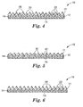
- FIG. 4 shows a series of parallel peaks 28 and 30 that are of different heights, separated by a series of parallel valleys 22.
- FIG. 5 shows a saw tooth pattern of alternating, parallel, asymmetric peaks 40 separated by a series of parallel, asymmetric valleys 42.
- peaks and valleys may terminate for a portion of the article.
- the valleys may either narrow or widen as the peak or valley progresses from one end of the article to the other.
- the height and/or width of a given peak or valley may change as the peak or valley progresses from one end of the article to the other.
- peaks and valleys are not critical to the invention provided that whatever patterned surface is employed, it provides the desired reduction in drag.
- the optimum dimensions are somewhat dependent upon the speed at which the substrate to be covered passes through the fluid (or the speed at which the fluid passes over the substrate).
- peaks having a height of at least about 10 micrometers (0.0004 inches) are useful.
- peaks having a height of as much as about 250 micrometers (0.010 inches) are useful.
- the peaks are at least about 20 micrometers (0.0008 inches) high for high speed uses (for example, aircraft).
- the peaks are as much as about 150 micrometers (0.006 inches) high for high speed uses (for example, aircraft).
- the peak-to-peak spacing between adjacent peaks likewise is not critical to the invention.
- a spacing of at least about 10 micrometers (0.0004 inches) is useful.
- a spacing of as much as about 250 micrometers (0.010 inches) is useful.
- a spacing of at least about 20 micrometers (0.0008 inches) is useful.
- a spacing of as much as about 150 micrometers (0.006 inches) is useful.
- the included angle between adjacent peaks can also vary.
- the valleys may be flat, round, or V-shaped.
- the peaks are generally V-shaped and have an included angle of at least about 15°.
- the included angle may be as much as about 140°.
- the included angle may be at least about 50°.
- the included angle may be as much as about 60°.
- Drag reduction articles according to the invention may be readily manufactured by a variety of techniques.
- the drag-reducing pattern may be imparted during the manufacture of layers 11 and/or 12, or alternatively, a pre-formed web comprising one or more of layers 11, 12, 14, and 16 may be provided and a drag-reducing pattern formed in layer 11.
- the drag reduction article can be wound about a core into roll form for easy storage, shipping, and use.
- the polymers for outer patterned backing layer 11 and intermediate layer 12 are coextruded (that is, extruded together at the same time).
- each of the layers could be extruded separately and thereafter joined together, for example, by lamination or adhesive bonding. Almost any combination of layers may be coextruded then joined to the remaining layers.
- the different layers may also be assembled by various sequential or tandem coating methods. Combinations of coating and extrusion are also contemplated.
- the patterned surface may be formed by embossing techniques utilizing heat and/or pressure. Of course, other techniques are also possible and will be readily thought of by those skilled in the art.
- the materials in adjacent layers are compatible and either adhere together by themselves or be capable of being adhered together so as to provide sufficient interlayer adhesion that the drag reduction article does not delaminate during normal use.
- a large proportion of acrylic polymer in intermediate layer 12 can provide good adhesion between outer patterned backing layer 11 and adhesive bonding layer 14.
- Intermediate layer 12 may be provided with a surface treatment, such as etching or corona treatment as described above, to promote good adhesion between intermediate layer 12 and outer patterned backing layer 11, or adhesive bonding layer 14, or both. Alternatively, such surface treatments may be employed to promote good adhesion directly between outer patterned backing layer 11 and adhesive bonding layer 14.
- Adhesive bonding layer 14 is applied to the surface of outer patterned backing layer 11 that is opposite the patterned surface.
- bonding layer 14 can be coated onto a web comprising outer patterned backing layer 11 that has been previously extruded. A temporary, removable, protective liner 16 may then be laminated to bonding layer 14.
- bonding layer 14 can be coated onto a protective liner 16 and transfer laminated to a pre-formed web comprising outer patterned backing layer 11 by passing the pre-formed web and the bonding layer-coated protective liner between rubber rolls, which may be heated if needed. The resulting drag reduction article is shown in FIG. 6.
- adhesive bonding layer is applied, using these same techniques, to the surface of intermediate layer 12 opposite that which is adjacent to outer patterned backing layer 11.
- Another useful technique comprises applying a radiation curable composition to a flexible carrier, contacting the radiation curable composition with a master bearing the positive structure of the desired pattern, and radiation curing the composition.
- the resulting tooling sheet may be removed from the master and subsequently used to impart a pattern to outer backer layer 11 by coating, extruding, or coextruding the materials for layers 11 and 12 onto the tooling sheet. Additional information about such manufacturing techniques can be found in U.S. Pat. No. 4,576,850 (Martens ); U.S. Pat. No. 5,183,597 (Lu ); and U.S. Pat. No. 5,468,540 (Lu ).
- Still another approach involves taking a web comprised of outer backing layer 11 and laminating a tooling sheet to layers 11 and 12 using heat and/or pressure in order to impart the pattern of the tooling sheet to the surface of outer backing layer 11.
- a tooling sheet can be advantageous in that it also acts as a carrier web to protect outer patterned backing layer 11 through any additional processing operations, such as corona treating, adhesive bonding layer attaching, slitting, or perforating. It may be removed prior to using the drag reduction article, or after application of drag reduction article 10 to a substrate or it can be removed at any time during the manufacture of the drag reduction article.
- the drag reduction articles of the invention may be readily applied to a variety of substrates to reduce the drag experienced when that substrate moves through a fluid medium or when a fluid moves past the substrate.
- the article is positioned on the substrate such that the patterned surface will provide maximum drag reduction.
- the patterned surface comprises parallel peaks and valleys
- maximum drag reduction is achieved when the peaks and valleys are generally parallel to the fluid flow.
- the drag reduction articles of the invention employing the bonding layers described herein are expected to possess excellent weather and fluid resistance as disclosed in U.S. Pat. No. 6,475,616 and PCT Publication No.
- WO 02/070623 may be easily applied over flat or smooth contoured surfaces, that is, essentially free of surface protrusions, for example, raised rivets, such as those typically found on the exterior surface of commercial aircraft.
- Providing perforations or other discontinuities (for example, slits) in the drag reduction article can facilitate applying the drag reduction article to a substrate and accommodates the passage of moisture and vapors through the article.
- a further advantage of the invention is its ease of manufacture and a decreased cost of production due to a reduced number of layers required for its construction.
- Drag reduction articles of the present invention do not contain a reinforcing layer, such as that described in U.S. Pat. No. 5,848,769 .
- Such materials are said to include thermoplastic polyurethanes and polyvinyl chloride. It has been found that sufficiently conformable drag reduction articles may be provided without employing such a layer. Further, elimination of the reinforcing layer is expected to contribute to improved fluid resistance in the present invention.
- a drag reduction article including outer patterned backing layer 11, and optionally intermediate layer 12 may be co-cured with the uncured composite article to form a finished composite article having a drag reduction article surface thereon.
- the uncured composite article serves as the bonding layer 14.
- a thin layer of adhesive bonding material 14 may be applied to outer patterned backing layer 11, or intermediate layer 12 when it is present, and the drag reduction article is placed over the uncured composite article and then co-cured with the uncured composite article to form a finished composite article having a drag reduction surface thereon.
- a drag reduction article having a pressure-sensitive adhesive bonding layer on one surface may be placed onto the uncured composite article and then co-cured with the uncured composite article to form a finished composite article having a drag reduction surface thereon.
- a drag reduction article of the invention having a curable adhesive layer may be placed onto a cured composite article and the curable adhesive of the drag reduction article is cured.
- hand pressure is used to bring the drag reduction articles in contact with the uncured composite articles followed by debulking (as described in Engineered Materials Handbook, Volume 1: Composites) to remove any entrapped air.
- the drag reduction article of the invention can be used to provide drag reduction surfaces on composite articles.
- a drag reduction article of the invention may be used in the initial production of a substrate having a drag reduction surface, for example, a composite article, or used in the field to provide such substrates in which case the adhesive bonding layer, if curable, may be cured at ambient temperature or may require elevated temperature.
- the required elevated temperature may be provided by known means, such as IR lamps, heat guns, portable heaters, and the like.
- the drag reduction article of the invention can be used on any substrate to which the adhesive bonding layer will bond thereto.
- substrates include painted surfaces, primed surfaces, metallic surfaces, ceramics, cured and un-cured composite surfaces, fluorinated polymer surfaces, plated surfaces, galvanized surfaces, and the like.
- a patterned tooling sheet was prepared from the following materials:
- the film with the solution thereon was passed through a squeeze roll nip with the solution contacting a cylinder engraved with a grooved pattern. While in contact with the engraved cylinder, the solution was exposed to a UV light source (medium pressure mercury lamp, 400 watts, from Actek International, Plainsville, IL), for approximately 0.1 - 1.0 second to cure the solution. The cured material was stripped from the cylinder and used as a carrier web/tooling sheet to impart the grooved pattern to the drag reduction article surface.
- a UV light source medium pressure mercury lamp, 400 watts, from Actek International, Plainsville, IL
- the pattern on the cured material surface had a cross-section similar to that of FIG. 2 with a 62.5 micrometers (2.5 mils) peak height, a 62.5 micrometers (2.5 mils) peak to peak spacing, and an included angle between adjacent peaks of 53°.
- the sample was then examined under a 100 power microscope to determine the sharpness of the profile produced.
- the sample had sharp peaks and valleys.
- a drag reduction article having a backing with a drag reduction pattern on one side and an adhesive bonding layer on the other side was prepared as follows:
- a blend of PVDF:PMMA / 90: 10 (weight ratio) was fed by a single screw extruder having a length:diameter ratio of 24:1 to a five-layer feedblock which in turn fed into a single layer extrusion die having a 914 mm x 1.02 mm (36 x 0.04 inches) opening.
- the extruder had multiple heating zones with the last zone set between 204.5 °C - 215.5 °C (400 - 420 °F).
- the coextrusion die temperature was set at 215.5 °C (420 °F).
- the extruder was plumbed to the die such that blend exited the die and was placed directly in contact with the carrier web/tooling sheet described above.
- the carrier web was fed through a nip consisting of a polished chrome roll and a matte-finished ground silicone rubber roll.
- the temperature of both nip rolls was maintained at 88 °C (190 °F).
- the hot extrudate was cast onto the carrier web/tooling sheet and immediately nipped between nip rolls at a roll pressure of 21 kg/cm (118 lbs per lineal inch). Surface speed of the rolls was 8.5 m (28 ft)/min.
- the resulting film had a total thickness, as measured from the top of the peaks to the opposite side of the backing layer of 114.3 micrometers (0.0045 inches) and exactly replicated the pattern of the carrier web/tooling sheet.
- the backing film was then corona treated on its unpatterned side after which it was laminated at room temperature to 3M TM 468 Laminating Adhesive Tape (an acrylic adhesive on a silicone release liner, available from 3M Company).
- the adhesive thickness was approximately 125 micrometers (0.005 inches).
- the drag reduction article was then examined under a 100 power microscope to determine the sharpness of the patterned profile produced.
- the patterned surface of the backing possessed sharp peaks and valleys.
Landscapes
- Engineering & Computer Science (AREA)
- Fluid Mechanics (AREA)
- Chemical & Material Sciences (AREA)
- Physics & Mathematics (AREA)
- Mechanical Engineering (AREA)
- Organic Chemistry (AREA)
- Ocean & Marine Engineering (AREA)
- General Engineering & Computer Science (AREA)
- Aviation & Aerospace Engineering (AREA)
- Combustion & Propulsion (AREA)
- Chemical Kinetics & Catalysis (AREA)
- Health & Medical Sciences (AREA)
- General Health & Medical Sciences (AREA)
- Physical Education & Sports Medicine (AREA)
- Laminated Bodies (AREA)
- Adhesive Tapes (AREA)
- Adhesives Or Adhesive Processes (AREA)
- Measuring Instrument Details And Bridges, And Automatic Balancing Devices (AREA)
- Thermistors And Varistors (AREA)
- Non-Adjustable Resistors (AREA)
- Supplying Of Containers To The Packaging Station (AREA)
- Separation By Low-Temperature Treatments (AREA)
- Manufacturing Of Electric Cables (AREA)
Abstract
Description
- This invention relates to articles that can be applied to surfaces to reduce the drag caused by fluids (for example, air, gas, water, etc.) flowing across such surfaces.
- It is desirable to reduce the drag caused by bodies passing through fluid media, such as an airplane moving through air, a boat moving through water, or a motor vehicle moving through air. Relatively small reductions in drag can significantly reduce the fuel needed to propel the body. Improved fuel economy can result.
- To enhance their utility, drag reduction articles should possess certain properties. For example, they should be weatherable. That is, the drag reduction articles should not deteriorate or lose performance as a result of exposure to ultraviolet radiation, wind, sand, rain, snow, ice, repeated and substantial changes in temperature, etc. Further, the drag reduction article should adhere well to the exterior of the vehicle to which it is applied, for example, an aircraft, and should have resistance to fluids to which it might be exposed to, for example, organic solvents. A certain degree of conformability is also desired to facilitate application to flat surfaces or smooth contoured ones, that is, those essentially free of surface protrusions, such as raised rivets. For some applications, the drag reduction article should remove cleanly and easily from a surface to which it has been applied. Finally, it is desirable that the drag reduction article be easily produced, for example, by minimizing the number of layers in its construction. By minimizing the number of layers required for a drag reduction article, its cost of manufacture can also be decreased.
- Various drag reduction articles are known and comprise a thermoplastic or thermoset polymeric film having a patterned surface that reduces drag. Examples of these articles can be found in
U.S. Pat. Nos. 4,986,496 ;5,069,403 ; and5,133,516, each to Marentic et al . The articles of Marentic et al. usefully reduce drag. Another example of drag reduction articles can be found inU.S. Pat. No. 5,848,769 to Fronek et al . The articles of Fronek et al. improve upon those of Marentic et al. by providing improved handling, removability, and weathering characteristics while usefully reducing drag. - This invention relates to a drag reduction article comprising:
- (a) an outer layer having an exposed, patterned surface that reduces the drag caused by a fluid flowing over the surface, wherein:
- (1) the outer layer comprises a blend of first and second polymers, the first polymer comprising polymerized units of vinylidene fluoride, and the second polymer comprising the polymerization product of a monomer selected from the group consisting of methyl methacrylate, ethyl methacrylate, butyl methacrylate, and combinations thereof; and
- (2) the exposed, patterned surface is a series of essentially parallel peaks separated by a series of essentially parallel valleys;
- (b) an adhesive bonding layer for bonding the drag reduction article to a surface; and
- (c) an intermediate layer between the outer layer and the adhesive bonding layer; wherein:
- the intermediate layer comprises:
- a blend of first and second polymers, the first polymer comprising polymerized units of vinylidene fluoride, and
- the second polymer comprising the polymerization product of a monomer selected from the group consisting of methyl methacrylate, ethyl methacrylate, butyl methacrylate, and combinations thereof; and
- the intermediate layer comprises:
- The invention will be more fully appreciated by referring to the following drawings in which similar reference numerals designate like or analogous components and in which:
- FIG. 1 is a fragmentary perspective view of one embodiment of a drag reduction article according to the invention;
- FIG. 2 is a sectional view taken along lines 2-2 in FIG. 1;
- FIG. 3 is sectional view similar to FIG. 2 but showing an alternative embodiment, of the invention in which the drag reduction articles bears graphic indicia;
- FIG. 4 is a sectional view analogous to FIG. 2 but showing a different patterned surface useful in drag reduction articles according to the invention; and
- FIG. 5 is a sectional view similar to FIG. 4 and illustrating another patterned surface useful in drag reduction articles according to the invention.
- FIG. 6 is sectional view similar to FIG. 2 but showing an alternative embodiment, of the invention.
- Turning now to the drawings, FIGS. 1 and 2 illustrate a
drag reduction article 10 according to the invention and which may be opaque, translucent, or transparent.Drag reduction article 10 comprises an outer patternedbacking layer 11 with an outer patternedsurface having peaks 20 andvalleys 22, an optionalintermediate layer 12, anadhesive bonding layer 14, and an optional temporary, removable,protective liner 16. The terms "outer patterned" and "outer exposed pattern" are used interchangeably herein. - Such articles are useful on vehicles, such as planes, trains, automobiles, boats, and ships, as well as other surfaces over which a fluid may flow, such as windmill rotor blades or the interior surface of a fluid-conveying conduit. They can be used on painted, primed (for example, epoxy primer, chromated primer), or bare surfaces. They can be used on metal surfaces, particularly aluminum surfaces, which can be an anodized surface, a chromate-treated surface (which results from treatment with Alodine 1200, available from Amchem Products, Inc., Abmoler, PA), or otherwise treated surface. They can be used on surfaces of composite materials, such as carbon fiber reinforced plastics, for example.
- In one embodiment,
drag reduction article 10 comprises abacking layer 11 with an outer exposed patterned surface, anadhesive bonding layer 14, and an optional temporary, removableprotective liner 16 and is free of a reinforcing layer, such as that described inU.S. Pat. No. 5,848,769 . Such materials are said to include thermoplastic polyurethanes and polyvinyl chloride. It has been found that sufficiently conformable drag reduction articles may be provided without employing such a layer. As a result, it is expected the present invention will exhibit an improved ease of manufacture and a decreased cost of production. It is also anticipated that the present invention will exhibit improved chemical fluid resistance. - In an alternative embodiment, the drag reduction article consists essentially of outer patterned
backing 11, anadhesive bonding layer 14, and an optional temporary, removable protective liner. - In another embodiment, drag reduction article comprises outer patterned
backing layer 11, anadhesive bonding layer 14, and anintermediate layer 12 between the backing and bonding layers, and is free of a reinforcing layer, as described inU.S. Pat. No. 5,848,769 . It has been found that sufficiently conformable drag reduction articles may be provided without employing such a layer. As a result, it is expected the present invention will exhibit an improved ease of manufacture, and a decreased cost of production. It is also anticipated the present invention will exhibit improved chemical fluid resistance. - In an alternative embodiment, the drag reduction article consists essentially of an outer patterned
backing layer 11 having an outer exposed patterned surface, anadhesive bonding layer 14, anintermediate layer 12 between the backing and bonding layers, and an optional temporary, removableprotective liner 16. - The drag reduction article (exclusive of bonding layer 14) typically and advantageously comprises thermoplastic materials so as to facilitate manufacturing the drag reduction article. Thermoplastic materials can be repeatedly reheated and reformed, which assists in manufacturing the drag reduction article by extrusion processes, as described more fully herein.
- Outer patterned
backing layer 11 is capable of being formed into a pattern (described more fully herein) that imparts drag reducing characteristics toarticle 10. In addition, outerpatterned backing layer 11 is sufficiently resistant to chemical and weather exposure to permit the use ofdrag reduction article 10 in aerospace applications. -
Intermediate layer 12 imparts good handling characteristics to the drag reduction article and promotes adhesion between outerpatterned backing layer 11 andadhesive bonding layer 14. The incorporation oflayer 12 also permits the use of an expanded selection of modifying materials inarticle 10, such as pigments, dyes, antioxidants, UV stabilizers, etc. that might not otherwise be employed due to compatibility issues with outerpatterned backing layer 11. - The
adhesive bonding layer 14 may be a pressure-sensitive adhesive; or a curable adhesive layer or an uncured composite article layer, either of which may be cured after application to a substrate. Theadhesive bonding layer 14 adheres the drag reduction article to a substrate, for example, the surface of an airplane, the hull of a boat or other watercraft, the surface of a motor vehicle, the surface of a windmill rotor blade, or the interior surface of a fluid-conveying conduit. - In order to achieve these desirable properties, outer
patterned backing layer 11 having an outer surface with an exposed pattern thereon andintermediate layer 12 are suitably provided as blends of different polymers, at least one of which has good chemical resistance and weatherability, and at least one of which has good bonding properties. ("Polymer" is used broadly in this context to encompass both homopolymers and copolymers; that is, polymers derived from more than one monomer.) Fluoropolymers, in particular those that contain polymerized units of vinylidene fluoride, have been found to have good chemical resistance and weatherability. Acrylic polymers, in particular those that contain polymerized units of short chain alkyl methacrylates, have been found to have good bonding properties and handling characteristics. - In one embodiment, outer
patterned backing layer 11 andintermediate layer 12 are formed as different blends of the fluoropolymer and the acrylic polymer, the actual amounts depending upon the desired balance between fluid resistance, ultraviolet (UV) radiation resistance, weather resistance, and stiffness afforded by the fluoropolymer, and adhesion, flexibility and handling ability imparted by the acrylic polymer. Outerpatterned backing layer 11 employs a higher weight percentage of the fluoropolymer where its UV radiation, weathering and chemical resistance properties are needed, whileintermediate layer 12 uses a higher percentage of acrylic polymer where good bonding properties are needed between outerpatterned backing layer 11 andadhesive bonding layer 14. In one embodiment, outerpatterned backing layer 11 comprises a blend of at least about 70% by weight fluoropolymer. In another embodiment, outerpatterned backing layer 11 comprises as much as about 30% by weight of acrylic polymer. In one embodiment, outer patterned backing layer comprises a blend of as much as about 90% by weight fluoropolymer. In another embodiment, outerpatterned backing layer 11 comprises at least about 10% by weight acrylic polymer. In a further embodiment, outerpatterned backing layer 11 comprises about 90% by weight fluoropolymer and 10% by weight acrylic polymer. Such blends enable outerpatterned backing layer 11 to withstand extended exposure to water, oil, fuel, solvents, hydraulic fluids, and the like, without a noticeable deterioration in its physical properties, performance, or appearance. Further, it is not appreciably affected by acid rain, bird dung, and other harsh environmental agents to which thedrag reduction article 10 may be exposed during normal use. In one embodiment,intermediate layer 12 comprises a blend of at least about 70% by weight acrylic polymer. In another embodiment,intermediate layer 12 comprises as much as about 30% by weight of fluoropolymer. In one embodiment,intermediate layer 12 comprises a blend of as much as about 90% by weight acrylic polymer. In another embodiment,intermediate layer 12 comprises at least about 10% by weight fluoropolymer. In a further embodiment,intermediate layer 12 comprises about 90% by weight acrylic polymer and 10% by weight fluoropolymer. Such blends enableintermediate layer 12 to impart good handling characteristics to the drag reduction article and promote adhesion between outerpatterned backing layer 11 andadhesive bonding layer 14. The incorporation ofintermediate layer 12 also permits the use of an expanded selection of modifying materials inarticle 10, such as pigments, dyes, antioxidants, UV stabilizers, etc. that might not otherwise be employed due to compatibility issues with outerpatterned backing layer 11. - Suitable vinylidene fluoride-containing fluoropolymers include poly(vinylidene fluoride) (PVDF). Also useful are copolymers derived from polymerized units of vinylidene fluoride and a monomer selected from the group consisting of ethylene, hexafluoropropylene, tetrafluoroethylene, and combinations thereof, and combinations of PVDF and copolymers of PVDF. Such materials tend to have a melt flow index (MFI) of about 6-120, when measured according to ASTM D-1238 at 230 °C and 5 kg, and an apparent viscosity of 400-30,000 Pascal · seconds, when measured at 240 °C and 50 sec-1 by conventional means using a capillary rheometer. PVDF is suitable because it can be formed into precise patterns to provide outer
patterned backing layer 11 with a drag reducing shape and provides stiffness. PVDF has the ability to retain a precise drag reducing pattern more easily than the thermoplastic materials previously used for drag reduction articles. - Various acrylic polymers may be used, for example, medium to low molecular weight acrylic resins having a weight average molecular weight below 750,000, including blends or copolymers comprising at least two materials selected from the group consisting of methyl methacrylate, ethyl methacrylate, butyl methacrylate, and methacrylate copolymers. Poly(methyl methacrylate) (PMMA) is suitable.
-
Layers - In one embodiment, outer
patterned backing layer 11 may be at least about 5 micrometers (0.0002 inches) thick. In another embodiment, outerpatterned backing layer 11 may be as much as about 410 micrometers (0.016 inches) thick. In one embodiment, outerpatterned backing layer 11 may be at least about 13 micrometers (0.0005 inches) thick. In another embodiment, outerpatterned backing layer 11 may be as much as about 40 micrometers (0.0015 inches) thick. When used withoutintermediate layer 12, outerpatterned backing layer 11 may be at least about 13 micrometers (0.0005 inches) thick. In another embodiment, outerpatterned backing layer 11 may be as much as about 410 micrometers (0.016 inches) thick when used withoutintermediate layer 12. - When used in combination with
intermediate layer 12, outerpatterned backing layer 11 maybe at least about 5 micrometers (0.0002 inches) thick. In another embodiment, outerpatterned backing layer 11 may be as much as about 410 micrometers (0.016 inches) thick when used in combination withintermediate layer 12.Intermediate layer 12 may be at least about 3 micrometers (0.0001 inches) thick. In another embodiment,intermediate layer 12 may be as much as about 410 micrometers (0.016 inches) thick. In a further embodiment,intermediate layer 12 may be as much as about 12 micrometers (0.0005 mils) thick. Overall, the combined thickness oflayers layers layers layers -
Layers adhesive bonding layer 14, depending on which layer will be adjacent to the bonding layer. Such treatment methods include corona treatment, particularly corona discharge in an atmosphere containing nitrogen, and about 0.1 to about 10 volume percent of an additive gas selected from the group consisting of hydrogen, ammonia, and mixtures thereof, as disclosed inU.S. Pat. No. 5,972,176 (Kirk et al. ). Another useful treatment method includes a chemical etch using sodium naphthalenide. Such treatment methods are disclosed in Polymer Interface and Adhesion, Souheng Wu, Ed., Marcel Dekker, Inc., NY and Basel, pp. 279 - 336 (1982); and Encyclopedia of Polymer Science and Engineering, Second Edition, Supplemental Volume, John Wiley & Sons, pp. 674 - 689 (1989). Another useful treatment method is the FLUOROETCH process, available from Acton Industries, Inc., Pittston, PA. Other treatment methods include the use of such materials as primers. These may be employed either in place of, or in addition to the surface treatments described above. An example of a useful primer is ADHESION PROMOTER #86A (a liquid primer, available from 3M Company, St. Paul, MN). - A
graphic layer 18 may be applied to outerpatterned backing layer 11 orintermediate layer 12 or, as shown in FIG. 3,adhesive bonding layer 14. - The
adhesive bonding layer 14 adheres the drag reduction article to a substrate, for example, the surface of an airplane, the hull of a boat or other watercraft, the surface of a motor vehicle, the surface of a windmill rotor blade, or the interior surface of a fluid-conveying conduit. - In one embodiment, the
adhesive bonding layer 14 is applied to outerpatterned backing layer 11 on the side opposite the side having the patterned surface.Adhesive bonding layer 14 may be selected from adhesives, such as room temperature pressure-sensitive adhesives (PSAs), hot melt PSAs, thermoplastics, or a curable adhesive, such as a moisture curing adhesive, thermosetting adhesive, or a prepreg material (for example, one containing a curable organic resin matrix and reinforcing material, such as inorganic fibers). In another embodiment whenintermediate layer 12 is employed, such bonding layers may be applied to the surface of intermediate layer opposite that which is adjacent to outerpatterned backing layer 11. - In one embodiment, the adhesive is a room temperature PSA. An example of a room temperature PSA is an acrylate pressure-sensitive adhesive. Such materials possess a four-fold balance of adhesion, cohesion, stretchiness, and elasticity, and a glass transition temperature (Tg) of less than about 20 °C. Thus, they are tacky to the touch at room temperature (for example, about 20 °C to about 25 °C), as can be determined by a finger tack test or by conventional measurement devices, and can easily form a useful adhesive bond with the application of light pressure. An acceptable quantitative description of a pressure-sensitive adhesive is given by the Dahlquist criterion line (as described in the Handbook of Pressure Sensitive Adhesive Technology, Second Edition, D. Satas, ed., Van Nostrand Reinhold, New York, NY, pages 171-176 (1989)), which typically indicates that materials having a storage modulus (G') of less than about 3 x 10⁵ Pascals (measured at 10 radian/second at a temperature of about 20 °C to about 22 °C) have pressure-sensitive adhesive properties while materials having a G' in excess of this value do not.
- Useful acrylic pressure-sensitive adhesives include those that comprise a polymer of an acrylate ester of acrylic acid with a non-tertiary alcohol. Multifunctional acrylates, copolymerizable photoinitiators, or combinations of the two may also be present so as to provide some crosslinking, which can contribute to easy removability, better fluids resistance and improved high temperature performance of the drag reduction article. Ultimately, removability is a balance among the peel adhesion, the degree of crosslinking, and the thickness of the bonding layer. Pressure-sensitive adhesives suitable for the bonding layer and methods for their preparation are disclosed in
U.S. Pat. No. 6,475,616 (Dietz et al ) and described below. - Useful thermally or moisture curable adhesives include epoxy resins (epoxide resin + curing agent), acrylates, cyano-acrylates, and urethanes (isocyanate terminated compound + active hydrogen-containing compound). The curable adhesives used in the drag reduction articles of the invention are non-tacky to the touch after curing; that is, after curing they cannot be reheated and reflowed. Further, drag reduction articles of the invention may be applied to prepreg material (that is, one containing a curable organic resin matrix and reinforcing material, such as inorganic fibers), also referred to herein as uncured composite articles. When used in this manner, the curable organic resin of the prepreg material may act as the
adhesive bonding layer 14 thereby eliminating the need for aseparate bonding layer 14 to be provided on the drag reduction article. - The acrylate pressure-sensitive adhesive copolymers used herein are advantageous because they show desirable adhesive properties over a broad temperature range, particularly at low temperatures, to a wide variety of substrates. In addition, they show desirable adhesive properties even after exposure to various fluids.
- Suitable poly(acrylates) are derived from: (A) at least one monofunctional alkyl (meth)acrylate monomer (that is, alkyl acrylate and alkyl methacrylate monomer); and (B) at least one monofunctional free-radically copolymerizable acid-containing reinforcing monomer. The reinforcing monomer has a homopolymer glass transition temperature (Tg) higher than that of the alkyl (meth)acrylate homopolymer and is one that increases the glass transition temperature and modulus of the resultant copolymer. Herein, "copolymer" refers to polymers containing two or more different monomers, including terpolymers, tetrapolymers, etc.
- In one embodiment, the monomers used in preparing the pressure-sensitive adhesive copolymers of the present invention include: Monomer A - a monofunctional alkyl (meth)acrylate monomer that, when homopolymerized, generally has a glass transition temperature of no greater than about 0 °C; and monomer B - a monofunctional free-radically copolymerizable acid-containing reinforcing monomer that, when homopolymerized, generally has a glass transition temperature of at least about 10 °C. The glass transition temperatures of the homopolymers of monomers A and B are typically accurate to within ±5 °C and are measured by differential scanning calorimetry.
- Monomer A, which is a monofunctional alkyl acrylate or methacrylate (that is, (meth)acrylic acid ester), contributes to the flexibility and tack of the copolymer. Exemplary materials used for monomer A have a homopolymer Tg of no greater than about 0 °C. In one embodiment, the alkyl group of the (meth)acrylate has an average of 4 to 20 carbon atoms, and in another embodiment, an average of 4 to 14 carbon atoms. The alkyl group can optionally contain oxygen atoms in the chain thereby forming ethers or alkoxy ethers, for example. Examples of monomer A include, but are not limited to, 2-methylbutyl acrylate, isooctyl acrylate, lauryl acrylate, 4-methyl-2-pentyl acrylate, isoamyl acrylate, sec-butyl acrylate, n-butyl acrylate, n-hexyl acrylate, 2-ethylhexyl acrylate, n-octyl acrylate, isooctyl acrylate, n-decyl acrylate, isodecyl acrylate, isodecyl methacrylate, and isononyl acrylate. Other examples include, but are not limited to, poly-ethoxylated or - propoxylated methoxy (meth)acrylate (that is, poly(ethylene/propylene oxide) mono-(meth)acrylate) macromers (that is, macromolecular monomers), polymethylvinyl ether mono(meth)acrylate macromers, and ethoxylated or propoxylated nonyl-phenol acrylate macromers. The molecular weight of such macromers is typically about 100 grams/mole to about 600 grams/mole, and in another embodiment, about 300 grams/mole to about 600 grams/mole. Suitable monofunctional (meth)acrylates that can be used as monomer A include 2-methylbutyl acrylate, isooctyl acrylate, lauryl acrylate, and poly(ethoxylated) methoxy acrylate (that is, methoxy terminated poly(ethylene glycol) mono-acrylate or poly(ethyleneoxide) mono-methacrylate). Combinations of various monofunctional monomers categorized as an A monomer can be used to make the pressure-sensitive copolymer used in making the appliques of the present invention.
- Monomer B, which is a monofunctional free-radically copolymerizable acid-containing reinforcing monomer increases the glass transition temperature of the copolymer. As used herein, "reinforcing" monomers are those that increase the modulus of the adhesive, and thereby its strength. Exemplary materials used for monomer B have a homopolymer Tg of at least about 10 °C. As used herein, "acid-containing" monomers are those that include acid functionality, such as an acrylic acid or a methacrylic acid functionality. Examples of monomer B include, but are not limited to, acrylic acid and methacrylic acid, itaconic acid, crotonic acid, maleic acid, and fumaric acid. A suitable reinforcing monofunctional acrylic monomer that can be used as monomer B includes acrylic acid and methacrylic acid. Combinations of various reinforcing monofunctional monomers categorized as a B monomer can be used to make the copolymer used in making the drag reduction articles of the present invention.
- Optionally, if desired, the copolymer can also include a monofunctional free-radically copolymerizable neutral or nonpolar reinforcing monomer in addition to the acid-containing monomer. Examples of such monomers include, but are not limited to, 2,2-(diethoxy)ethyl acrylate, hydroxyethyl acrylate or methacrylate, 2-hydroxypropyl acrylate or methacrylate, methyl methacrylate, isobutyl acrylate, n-butyl methacrylate, norbornyl acrylate, isobornyl acrylate, 2-(phenoxy)ethyl acrylate or methacrylate, biphenylyl acrylate, t-butylphenyl acrylate, cyclohexyl acrylate, dimethyladamantyl acrylate, 2-naphthyl acrylate, phenyl acrylate, and N-vinyl pyrrolidone. Combinations of such neutral reinforcing monofunctional monomers can be used to make the copolymer used in making the appliques of the present invention.
- In one embodiment, the acrylate copolymer is formulated to have a resultant Tg of less than about 25 °C and in another embodiment, less than about 0 °C. Such acrylate copolymers suitably include 80% by weight to 96% by weight of at least one alkyl (meth)acrylate repeat unit and 4% by weight to 20% by weight of at least one copolymerizable acid-containing reinforcing repeat unit. In another suitable embodiment, the acrylate copolymers include 85% by weight to 95% by weight of at least one alkyl (meth)acrylate repeat unit and 5% by weight to 15% by weight of at least one copolymerizable acid-containing reinforcing repeat unit. These weight percentages are based on the total weight of the monomers.
- One or more nonionic crosslinking agents that may, or may not, be copolymerizable with monomers A and B, can be used in the pressure-sensitive adhesives of the appliques of the present invention if desired. A crosslinking agent is referred to herein as component C. Typically, component C modifies the adhesion of the pressure-sensitive adhesive and improves its cohesive strength. The crosslinking agent typically produces chemical crosslinks (for example, covalent bonds). Prior to application of the drag reduction article to a substrate, the crosslinking functionality is consumed, that is, it is essentially completely reacted with monomers A and B or copolymers thereof. Crosslinking can contribute to easy removability, better fluids resistance and improved high temperature performance of the drag reduction article.
- When component C contains ethylenic unsaturation, it is incorporated into the backbone of the copolymer by copolymerization with monomers A and B through the ethylenic unsaturation. Such crosslinking agents are disclosed in
U.S. Pat. Nos. 4,379,201 (Heilmann et al. );4,737,559 (Kellen et al. );5,073,611 (Rehmer et al. ); and5,506,279 (Babu et al. ). Alternatively, component C can be essentially independent of the polymeric backbone. Materials of this type can cause crosslinking by, for example, reaction with the pendant carboxylic acid group of monomer B as disclosed inU.S. Pat. No. 5,604,034 (Matsuda ), or by photoactivated hydrogen abstraction as disclosed inU.S. Pat. Nos. 4,330,590 (Vesley ) and4,329,384 (Vesley ). Matsuda discloses the use of multifunctional crosslinking agents whose functionalities are reactive with carboxylic acid groups, while Vesley describes additives that can cause crosslinking upon exposure to ultraviolet radiation (for example, radiation having a wavelength of about 250 nanometers to about 400 nanometers). - In one embodiment, component C is (1) a copolymerizable olefinically unsaturated compound, which, in the excited state, is capable of abstracting hydrogen; (2) a compound having at least two reactive functional groups reactive with carboxylic acid groups; or (3) a noncopolymerizable compound which, in the excited state, is capable of abstracting hydrogen. Component C1 is a free-radically polymerizable monomer capable of polymerizing with monomers A and/or B. Components C2 and C3 are essentially free of olefinic unsaturation and thus typically not copolymerizable with monomers A and/or B. Combinations of various crosslinking agents can be used to make the pressure-sensitive adhesive of the present invention.
- One type of nonionic crosslinking agent (that is, component C1) is an olefinically unsaturated compound that is copolymerized with monomers A and B and generates free radicals on the polymer upon irradiation of the polymer. Examples of such a compound include an acrylated benzophenones, as described in
U.S. Pat. No. 4,737,559 (Kellen et al. ); p-aciyloxy-benzophenone, which is available from Sartomer Company, Exton, PA; and monomers described inU.S. Pat. No. 5,073,611 (Rehmer et al. ), including p-N-(methacryloyl-4-oxapentamethylene)-carbamoyloxybenzophenone, N-(benzoyl-p-phenylene)-N'-(methacryloxymethylene)-carbodiimide, and p-acryloxy-benzophenone.U.S. Pat. No. 5,506,279 (Babu et al. ) at columns 5-6, describes another suitable olefinically unsaturated crosslinking agent referred to therein asFormula 2, which is {2-[4-(2-hydroxy-2-methyl-propan-1-one)phenoxy]}ethyl(2-methyl-2-(2-methyl-2-propen-1-one)amino)propanoate. The olefinically unsaturated compound which, in the excited state, is capable of abstracting hydrogen suitably includes acrylic functionality. Combinations of such crosslinking agents can be used to make the pressure-sensitive adhesive used in the present invention. - A second type of nonionic crosslinking agent (that is, component C2) is a crosslinking compound which is essentially free of olefinic unsaturation and is capable of reacting with the carboxylic acid groups of monomer B. It includes at least two functional groups reactive with carboxylic acid groups. It may be added to a mixture of monomers A and B prior to their polymerization, or after they have been formed into a partially polymerized syrup, or to a copolymer of monomers A and B. Examples of such components include, but are not limited to, 1,4-bis(ethyleneiminocarbonylamino)benzene; 4,4-bis(ethyleneiminocarbonylamino)diphenylmethane; 1,8-bis(ethyleneiminocarbonylamino)octane; 1,4-tolylene diisocyanate; and 1,6-hexamethylene diisocyanate, as described in
U.S. Pat. No. 5,604,034 (Matsuda ). Another example is N,N'-bis-1,2-propyleneisophthalamide, as described inU.S. Pat. No. 4,418,120 (Kealy et al. ). Other such crosslinking agents are available from K.J. Quin and Co., Seabrook, NH, and EIT Inc., Lake Wyllie, SC. Other examples of C2 crosslinking agents include diepoxides, dianhydrides, bis(amides), and bis(imides). Combinations of such crosslinking agents can be used to make the pressure-sensitive adhesive used in the present invention. - A third type of nonionic crosslinking agent (that is, component C3) is a compound which is essentially free of olefinic unsaturation, is noncopolymerizable with monomers A and B, and, in the excited state, is capable of abstracting hydrogen. It is added to a copolymer of monomers A and B, or a partially polymerized syrup of monomers A and B. Upon irradiation of the mixture, component C3 generates free radicals on the polymer or partially polymerized material. Examples of such components include, but are not limited to, 2,4-bis(trichloromethyl)-6-(4-methoxy)phenyl)-s-triazine; 2,4-bis(trichloromethyl)-6-(3,4-dimethoxy)phenyl)-s-triazine; 2,4-bis(trichloromethyl)-6-(3,4,5-trimethoxy)phenyl)-s-triazine; 2,4-bis(trichloromethyl)-6-(2,4-dimethoxy)phenyl)-s-triazine; 2,4-bis(trichloromethyl)-6-(3-methoxy)phenyl)-s-triazine, as described in
U.S. Pat. No. 4,330,590 (Vesley ), and 2,4-bis(trichloromethyl)-6-naphthenyl-s-triazine and 2,4-bis(trichloromethyl)-6-(4-methoxy)naphthenyl-s-triazine, as described inU.S. Pat. No. 4,329,384 (Vesley ). Combinations of such crosslinking agents can be used to make the pressure-sensitive adhesive used in the present invention. - Another type of crosslinking agent that can be used in addition to one or more of components C1-C3, is an acrylic crosslinking monomer (component C4) containing at least two acrylic moieties. Suitable such materials have an average of less than about 12 atoms in the chain between acrylic groups. Examples of this type of crosslinking agent include, but are not limited to, trimethylolpropane triacrylate, 1,6-hexanediol diacrylate, pentaerythritol tetraacrylate, 1,2-ethylene glycol diacrylate, dodecyl diacrylate, and the diacrylate of ethylene oxide modified bisphenol A.
- If used, the crosslinking agent is used in an effective amount, by which is meant an amount that is sufficient to cause crosslinking of the pressure-sensitive adhesive to provide adequate cohesive strength to produce the desired final adhesion properties to the substrate of interest. In one embodiment, the crosslinking agent is used in an amount of about 0.01 part to about 2 parts by weight, based on 100 parts of the copolymer.
- If a photocrosslinking agent has been used, the adhesive can be exposed to ultraviolet radiation having a wavelength of about 250 nm to about 400 nm. The radiant energy in this suitable range of wavelength required to crosslink the adhesive is about 100 millijoules/centimeter2 (mJ/cm2) to about 1,500 mJ/cm2, and in another embodiment, about 200 mJ/cm2 to about 800 mJ/cm2.
- The acrylate pressure-sensitive adhesives of the present invention can be synthesized by a variety of free-radical polymerization processes, including solution, radiation, bulk, dispersion, emulsion, and suspension polymerization processes. Polymerization of the monomers to form the copolymer useful in the pressure-sensitive adhesive composition of the present invention is typically carried out using thermal energy, electron-beam radiation, ultraviolet radiation, and the like. Such polymerizations can be facilitated by a polymerization initiator, which can be a thermal initiator or a photoinitiator. Examples of suitable photoinitiators include, but are not limited to, benzoin ethers, such as benzoin methyl ether and benzoin isopropyl ether, substituted benzoin ethers, such as anisoin methyl ether, substituted acetophenones, such as 2,2-dimethoxy-2-phenylacetophenone, and substituted alpha-ketols, such as 2-methyl-2-hydroxypropiophenone. Examples of commercially available photoinitiators include IRGACURE 651 and DAROCUR 1173, both available from Ciba-Geigy Corp., and LUCERIN TPO from BASF, Parsippany, NJ. Examples of suitable thermal initiators include, but are not limited to, peroxides, such as dibenzoyl peroxide, dilauryl peroxide, methyl ethyl ketone peroxide, cumene hydroperoxide, dicyclohexyl peroxydicarbonate, as well as 2,2-azo-bis(isobutryonitrile), and t-butyl perbenzoate. Examples of commercially available thermal initiators include VAZO 64, available from ACROS Organics, Pittsburgh, PA, and LUCIDOL 70, available from Elf Atochem North America, Philadelphia, PA. The polymerization initiator is used in an amount effective to facilitate polymerization of the monomers. The polymerization initiator is suitably used in an amount of 0.1 part to 5.0 parts by weight, and in another embodiment, 0.2 part to 1.0 part by weight, based on 100 parts of the copolymer.
- If a photocrosslinking agent is used, the coated adhesive can be exposed to ultraviolet radiation having a wavelength of about 250 nm to about 400 nm. The radiant energy in this suitable range of wavelength required to crosslink the adhesive is about 100 millijoules/cm2 to about 1,500 millijoules/cm2, and in another embodiment, about 200 millijoules/cm2 to about 800 millijoules/cm2.
- The copolymers of the present invention can be prepared by a variety of techniques, which may or may not include solvent or chain transfer agents (for example, CBr4) to control molecular weight. These techniques may involve the use of appropriate polymerization initiators. A suitable solvent-free polymerization method using monomers A, B, and a crosslinking agent is disclosed in
U.S. Pat. No. 4,379,201 (Heilmann et al. ). Initially, a mixture of monomers A and B is polymerized with a portion of a photoinitiator by exposing the mixture to UV radiation in an inert environment for a time sufficient to form a coatable base syrup, and subsequently adding a crosslinking agent and the remainder of the photoinitiator. This final syrup containing a crosslinking agent (for example, having a Brookfield viscosity of about 100 centipoise to about 6000 centipoise at 23 °C, as measured with a No. 4 LTV spindle, at 60 revolutions per minute) is then coated onto a substrate, such as a backing. Once the syrup is coated onto a backing, further polymerization and crosslinking is typically carried out in an inert environment (that is, an environment that is nonreactive with the monomer mixture). Suitable inert environments include nitrogen, carbon dioxide, helium, and argon, which exclude oxygen. A sufficiently inert atmosphere can be achieved by covering a layer of the photoactive syrup with a polymeric film, such as silicone-treated polyethylene terephthalate (PET) film, that is transparent to UV radiation or e-beam and irradiating through the film in air. - A suitable solution polymerization method for preparing a copolymer using monomers A, B, and optionally a crosslinking agent, is disclosed in
U.S. Pat. No. 5,073,611 (Rehmer et al. ). Suitable solvents for such preparation methods include, for example, hydrocarbons, such as benzene, toluene, xylene, normal hexanes, cyclohexane, as well as esters, alcohols, ethers, and mixtures thereof. For carrying out the polymerization in solution, some or all of the solvent is heated with some of the monomer mixture and some or all of the thermal initiator. When the polymerization begins, the remainder of the monomer mixture, and where relevant, the remainder of the thermal initiator and the solvent are added. After polymerization, the composition can be coated onto a backing and the solvent can be removed by evaporation with or without heat. - A latex polymerization method for preparing a copolymer using monomers A, B, and a crosslinking agent, is disclosed in
U.S. Pat. No. 5,424,122 (Crandall et al. ). For example, a latex emulsion polymerization is carried out by combining monomers A, B, and a crosslinking agent, an oleophilic nonionic free radical initiator, water, and a nonionic surfactant. The mixture is homogenized to form an emulsion followed by initiation of free radical polymerization, typically done using heat, while agitating the emulsion under an inert atmosphere. After polymerization, the latex can be coated onto a backing and dried, typically at a temperature of at least about 65 °C. If necessary, water can be added or removed to reach an appropriate coating viscosity. - A pressure-sensitive adhesive composition may be applied to the outer
patterned backing layer 11, orintermediate layer 12 when it is employed, by a variety of coating methods including knife coating, slotted knife coating, reverse roll coating, coextrusion, or lamination (for example, if the adhesive has been initially coated onto a release liner). If the composition includes a solvent, it is then dried at a temperature (for example, 65 °C to 120 °C) and a time (for example, several minutes to about one hour) so as to provide a drag reduction article. The thickness of the layer of adhesive may vary over a broad range of about 10 micrometers to hundreds of micrometers. - Once the adhesive composition has been substantially fully cured and optionally crosslinked so as to provide a drag reduction article, the adhesive surface of the article may, optionally, be protected with a temporary, removable release liner (that is, protective liner) such as a paper liner or plastic films, such as polyolefin (for example, polyethylene or polypropylene) or polyester (for example, polyethylene terephthalate) film. Such paper or films may be treated with a release material, such as silicones, waxes, fluorocarbons, and the like. Only after the adhesive composition has been substantially fully cured and optionally crosslinked such that there is substantially no unsaturation are the drag reduction articles of the present invention applied to a substrate.
- The outer
patterned backing layer 11 of the present invention may be adhered to a substrate using a curableadhesive bonding layer 14, such as a thermally or moisture curable adhesive. Alternatively, such bonding layers may be applied tointermediate layer 12 when it is employed. Examples of such curable adhesives include epoxy resins (epoxide resin + curing agent), acrylates, cyano-acrylates, and urethanes. The curable adhesives used in the drag reduction articles of the invention are non-tacky to the touch after curing and are thermosetting. - Epoxide resins useful in the drag reduction articles of the invention are any organic compounds having at least one oxirane ring, that is,

- Useful epoxide resins include those which contain cyclohexene oxide groups, such as the epoxycyclohexane carboxylates, typified by 3,4-epoxycyclohexylmethyl-3,4-epoxycyclohexane carboxylate, 3,4-epoxy-2-methylcyclohexylmethyl-3,4-epoxy-2-methycyclohexane carboxylate, and bis(3,4-epoxy-6-methylcyclohexylmethyl) adipate. For a more detailed list of useful epoxides of this nature, reference may be made to
U.S. Pat. No. 3,117,099 . - Further epoxide resins which are particularly useful in the practice of this invention include glycidyl ether monomers of the formula:

U.S. Pat. No. 3,018,262 . - There are a host of commercially available epoxide resins that can be used in this invention. In particular, epoxides which are readily available include styrene oxide, vinylcyclohexene oxide, glycidol, glycidyl methacrylate, diglycidyl ether of Bisphenol A (for example, those available under the trade designations "EPON 828", "EPON 1004", and "EPON 1001F" from Shell Chemical Company, Houston, TX, and "DER-332" and "DER-334", from Dow Chemical Company, Midland, MI), diglycidyl ether of Bisphenol F (for example, those under the trade designations "ARALDITE GY281" from Ciba-Geigy Corp., and "EPON 862" from Shell Chemical Company), vinylcyclohexane dioxide (for example, having the trade designation "ERL-4206" from Union Carbide Corporation, Midland, MI), 3,4-epoxycyclohexyl-methyl-3,4-epoxycyclohexene carboxylate (for example, having the trade designation "ERL-4221" from Union Carbide Corporation), 2-(3,4-epoxycyclohexyl-5,5-spiro-3,4-epoxy) cyclohexane-metadioxane (for example, having the trade designation "ERL-4234" from Union Carbide Corporation), bis(3,4-epoxycyclohexyl) adipate (for example, having the trade designation "ERL-4299" from Union Carbide Corporation), dipentene dioxide (for example, having the trade designation "ERL-4269" from Union Carbide Corporation), epoxidized polybutadiene (for example, having the trade designation "OXIRON 2001" from FMC Corporation), flame retardant epoxide resins (for example, having the trade designation "DER-542", a brominated bisphenol type epoxy resin available from Dow Chemical Company), 1,4-butanediol diglycidyl ether (for example, having the trade designation "ARALDITE RD-2" from Ciba-Geigy Corp.), diglycidyl ether of hydrogenated Bisphenol A based epoxide resins (for example, having the trade designation "EPONEX 1510" from Shell Chemical Company), and polyglycidyl ether of phenol-formaldehyde novolak (for example, having the trade designations "DEN-431" and "DEN-438" from Dow Chemical Company).
- The term "curing agent" is used broadly to include not only those materials that are conventionally regarded as curing agents but also those materials that catalyze epoxy polymerization as well as those materials that may act as both curing agent and catalyst. Suitable curing agents for the epoxide resin include, for example, room temperature curing agents, heat-activated curing agents, and combinations thereof, and photolytically activated curing agents. Room temperature curing agents and heat-activated curing agents can include, for example, blends of epoxy homopolymerization type curing agents and addition type curing agents. The curing agents react at temperatures of between about room temperature and about 200 °C, about room temperature and 150 °C, or alternatively between about room temperature and about 115 °C. If the curing agents are used in epoxy resins that are used to make prepregs to make composite articles, then suitable curing agents react at temperatures in the range of 200 °F (93 °C) to 350 °F (177°C), and in another embodiment, 200 °F (93 °C) to 250 °F (121 °C).
- Examples of suitable curing agents include polybasic acids and their anhydrides, for example, di-, tri- and higher carboxylic acids, such as oxalic acid, phthalic acid, terephthalic acid, succinic acid, maleic acid, alkyl and alkenyl substituted succinic acids, tartaric acid, and anhydrides, for example, phthalic anhydride, succinic anhydride, maleic anhydride, nadic anhydride and pyromellitic anhydride; polymerizable unsaturated acids, for example, those containing at least 10 carbon atoms, for example, dodecendioic acid, 10,12-eicosadiendioic acid; and mercaptans.
- Examples of other suitable curing agents include nitrogen containing compounds, for example, benzyldimethylamine, benzylamine, N,N-diethyl aniline, melamine, pyridine, hydrazides, and aromatic polyamines, such as o-, m-, and p-phenylene diamine, 4,4'-diaminodiphenyl sulfone, 3,3'-diaminodiphenyl sulfone, and 4,4'-diaminodiphenyl sulfide, 4,4'-diaminodiphenyl ketone, 4,4'-diaminodiphenyl ether, 4,4'-diaminodiphenyl methane, 1,3-propanediol-bis(4-aminobenzoate), fluorene-containing amines (for example, 9,9-bis(4-aminophenyl)fluorene, 9,9-bis(3-methyl-4-aminophenyl)fluorene, 9,9-bis(3,5-dimethyl-4-methylaminophenyl)fluorene, 9,9-bis(3,5-dimethyl-4-aminophenyl)fluorene, 9,9-bis(3,5-diisopropyl-4-aminophenyl)fluorene, and 9,9-bis(3-chloro-4-aminophenyl)fluorene); 1,4-bis[α-(4-aminophenyl)-α-methylethyl]benzene, 1,4-bis[α-(4-amino-3,5-dimethylphenyl)-α-methylethyl]benzene, bis(4-amino-3-methylphenyl)sulfone, 1,1'-biphenyl-3,3'-dimethyl-4,4'-diamine, 1,1'-biphenyl-3,3'-dimethoxy-4,4'-diamine, 4,7,10-trioxatridecane-1,13-diamine, and diaminonaphthalenes.
- Suitable curing agents include, for example, aliphatic nitrogen-containing compounds, including poly(ether) amines, guanidines (for example, dicyandiamide and tetramethyl guanidine), imidazoles (for example, 2-ethyl-4-methyl imidazole), cyclohexylamine, diethylenetriamine, triethylenetetraamine, cyclohexyldiamine, tetramethylpiperamine, N,N-dibutyl-1,3-propane diamine, N,N-diethyl-1,3-propane diamine, 1,2-diamino-2-methyl-propane, 2,3-diamino-2-methylbutane, 2,3-diamino-2-methylpentane, and 2,4-diamino-2,6-dimethyloctane.
- Examples of suitable phenolic curing agents include polyhydric phenols, for example, pyrocatechol, resorcinol, hydroquinone, 4,4'-dihydroxydiphenyl methane, 4,4'-dihydroxydiphenyl dimethylmethane, 4,4'-dihydroxy-3,3'-dimethyldiphenyl methane, 4,4'-dihydroxydiphenyl methylmethane, 4,4'-dihydroxydiphenyl cyclohexane, 4,4'-dihydroxy-3,3'-dimethyldiphenyl dimethylmethane, 4,4'-dihydroxydiphenyl sulfone, and tris-(4-hydroxyphenyl)methane; and 9,9-bis(4-hydroxyphenyl) fluorene and ortho-substituted analogs thereof.
- Other useful curing agents include chloro-, bromo-, and fluoro-containing Lewis acids of aluminum, boron, antimony, and titanium, such as aluminum trichloride, aluminum tribromide, boron trifluoride, antimony pentafluoride, titanium tetrafluoride, and the like. It is also desirable at times that these Lewis acids be blocked to increase the latency of adhesive compositions containing them. Representative of blocked Lewis acids are BF3-monoethylamine, and the adducts of SbF5X, in which X is a halogen, -OH, or -OR1 in which R1 is the residue of an aliphatic or aromatic alcohol, aniline, or a derivative thereof, as described in
U.S. Pat. No. 4,503,211 . - Suitable photolytically activated curing agents include, for example, iodonium and sulfonium salts of antimony and cobalt, and bis(arene) iron compounds.
- Examples of commercially available curing agents suitable for use in the epoxides include EPI-CURE 8535-W-50 and EPI-CURE 8537-WY-60 (available from Shell Chemical Company), HY 955 (available from Ciba Specialty Chemicals Corporation), AMICURE CG-1400, ANCAMINE 2337S, CUREZOL 2E4MZ, and CUREZOL PHZ-S (available from Air Products, Pacific Anchor Chemical, Allentown, PA), and DCA-221 (available from Dixie Chemical Company, Pasadena, TX).
- The curing agent may be present in an amount of 2 to 110 parts by weight, per 100 parts by weight of the epoxide resin. When the curing agent is a carboxylic acid, a guanidine, a phenol, an anhydride, or a primary or secondary amine, the curing agent suitably is present in about 0.5 to about 1.7 equivalents of acid, anhydride, or amine per equivalent of epoxide group. When the curing agent is an anhydride or a phenol, accelerators may be added in amounts of about 0.1% to about 5.0% based on the weight of epoxide resin. Accelerators may also be used alone and in the amounts noted. Examples of suitable accelerators include aromatic tertiary amines, such as benzyldimethyl amine, and imidazoles, such as 2-ethyl-4-methylimidazole. Lewis acids are used in amounts of between about 0.1 and about 5% by weight based on the total weight of the epoxide resin.
- Useful epoxy resin adhesives include 3M™ Scotch-Weld™ epoxy resin adhesives available from 3M Company, for example, having product names DP-100; DP-105; DP-110; DP-125; DP-190; DP-270; DP-420; DP-460; 1751; 1833; 1838; 2158; 2210; 2216; and 3601.
- Other useful epoxy resin compositions are those that contain glycidyl ethers of hydroxy-phenylfluorene and/or an aminophenyl fluorene curing agent. These and other useful epoxy resin compositions that may be used as a curable adhesive are generally described in
U.S. Pat. Nos. 4,684,678 ;4,707,534 ;4,777,084 ;5,276,106 ;5,369,192 ;5,728,755 ; and6,054,221 . - Commercially available examples of curable crosslinking acrylate adhesives include 3M™ Scotch-Weld™ DP-8005 and the Pronto™ Instant Adhesives line of cyano-acrylate adhesives (available from 3M Company).
- Useful urethane adhesives include those that cure by exposure to moisture and crosslink. Commercially available curable urethane adhesives include those having the product names of 3M™ Scotch-Weld™ DP-605NS; 3592; 3535; and 3549 (available from 3M Company).
- The thickness of the
adhesive bonding layer 14 is not critical and may be at least about 2.5 micrometers (0.0001 inches) thick. In another embodiment, theadhesive bonding layer 14 may be as much as about 125 micrometers (0.005 inches) thick. In one embodiment,adhesive layer 14 is at least about 13 micrometers (0.0005 inches) thick. In another embodiment,adhesive bonding layer 14 may be as much 50 micrometers (0.002 inches) thick. If the adhesive bonding layer thickness is greater than about 125 micrometers, then it may become more susceptible to swelling by fluids and the weight of the article may be unnecessarily increased. However, if the bonding layer thickness is less than about 2.5 micrometers, it may not provide enough adhesion to hold the drag reduction article in place during use. -
Drag reduction article 10 may further and optionally include atemporary liner 16 that protectsadhesive bonding layer 14 from contamination by dirt and other materials and which is removed shortly before the drag reduction article is applied to a surface.Liner 16 may be provided as, for example, an untreated polyolefin sheet, or a silicone- or fluorosilicone-treated paper or plastic sheet. - The outer
patterned backing layer 11 includes a patterned outer surface adapted to reduce the resistance (drag) to a fluid (for example, air, gas, water, etc.) flowing overlayer 11. In general, and still referring to FIGS. 1 to 3, the patterned surface comprises a series of essentiallyparallel peaks 20 separated by a series of essentiallyparallel valleys 22. In cross-section the patterned surface may assume a variety of wave forms. For example, FIGS. 1 to 3 show a symmetric saw tooth pattern in which each of the peaks are identical as are each of the valleys. FIG. 4 shows a series ofparallel peaks parallel valleys 22. FIG. 5 shows a saw tooth pattern of alternating, parallel,asymmetric peaks 40 separated by a series of parallel,asymmetric valleys 42. - While only continuous peaks and valleys are shown, a discontinuous pattern of peaks and valleys is also contemplated. Thus, for example, the peaks and valleys may terminate for a portion of the article. The valleys may either narrow or widen as the peak or valley progresses from one end of the article to the other. Still further, the height and/or width of a given peak or valley may change as the peak or valley progresses from one end of the article to the other.
- The dimensions of the peaks and valleys are not critical to the invention provided that whatever patterned surface is employed, it provides the desired reduction in drag. The optimum dimensions are somewhat dependent upon the speed at which the substrate to be covered passes through the fluid (or the speed at which the fluid passes over the substrate). For more discussion on this topic, see AIAA-88-0138, "Drag Reduction for External Boundary Layers Using Riblets and Polymers," L.W. Reidy and G.W. Anderson, presented at the AIAA 26th Aerospace Sciences Meeting, January 11-14, 1988 at Reno, NV. However, it has been found that peaks having a height of at least about 10 micrometers (0.0004 inches) are useful. In another embodiment, peaks having a height of as much as about 250 micrometers (0.010 inches) are useful. In one embodiment, the peaks are at least about 20 micrometers (0.0008 inches) high for high speed uses (for example, aircraft). In another embodiment, the peaks are as much as about 150 micrometers (0.006 inches) high for high speed uses (for example, aircraft). The peak-to-peak spacing between adjacent peaks likewise is not critical to the invention. A spacing of at least about 10 micrometers (0.0004 inches) is useful. In another embodiment, a spacing of as much as about 250 micrometers (0.010 inches) is useful. For aircraft applications, a spacing of at least about 20 micrometers (0.0008 inches) is useful. In another embodiment, a spacing of as much as about 150 micrometers (0.006 inches) is useful. The included angle between adjacent peaks can also vary. The valleys may be flat, round, or V-shaped. The peaks are generally V-shaped and have an included angle of at least about 15°. In another embodiment, the included angle may be as much as about 140°. In one embodiment, the included angle may be at least about 50°. In another embodiment, the included angle may be as much as about 60°.
- Drag reduction articles according to the invention may be readily manufactured by a variety of techniques. For example, the drag-reducing pattern may be imparted during the manufacture of
layers 11 and/or 12, or alternatively, a pre-formed web comprising one or more oflayers layer 11. Once manufactured, the drag reduction article can be wound about a core into roll form for easy storage, shipping, and use. - In one approach, the polymers for outer
patterned backing layer 11 andintermediate layer 12 are coextruded (that is, extruded together at the same time). Alternatively, each of the layers could be extruded separately and thereafter joined together, for example, by lamination or adhesive bonding. Almost any combination of layers may be coextruded then joined to the remaining layers. The different layers may also be assembled by various sequential or tandem coating methods. Combinations of coating and extrusion are also contemplated. The patterned surface may be formed by embossing techniques utilizing heat and/or pressure. Of course, other techniques are also possible and will be readily thought of by those skilled in the art. - Generally, the materials in adjacent layers are compatible and either adhere together by themselves or be capable of being adhered together so as to provide sufficient interlayer adhesion that the drag reduction article does not delaminate during normal use. A large proportion of acrylic polymer in
intermediate layer 12 can provide good adhesion between outerpatterned backing layer 11 andadhesive bonding layer 14.Intermediate layer 12 may be provided with a surface treatment, such as etching or corona treatment as described above, to promote good adhesion betweenintermediate layer 12 and outerpatterned backing layer 11, oradhesive bonding layer 14, or both. Alternatively, such surface treatments may be employed to promote good adhesion directly between outerpatterned backing layer 11 andadhesive bonding layer 14. -
Adhesive bonding layer 14 is applied to the surface of outerpatterned backing layer 11 that is opposite the patterned surface. For example,bonding layer 14 can be coated onto a web comprising outerpatterned backing layer 11 that has been previously extruded. A temporary, removable,protective liner 16 may then be laminated tobonding layer 14. Alternatively,bonding layer 14 can be coated onto aprotective liner 16 and transfer laminated to a pre-formed web comprising outerpatterned backing layer 11 by passing the pre-formed web and the bonding layer-coated protective liner between rubber rolls, which may be heated if needed. The resulting drag reduction article is shown in FIG. 6. Whenintermediate layer 12 is employed, adhesive bonding layer is applied, using these same techniques, to the surface ofintermediate layer 12 opposite that which is adjacent to outerpatterned backing layer 11. - Another useful technique comprises applying a radiation curable composition to a flexible carrier, contacting the radiation curable composition with a master bearing the positive structure of the desired pattern, and radiation curing the composition. The resulting tooling sheet may be removed from the master and subsequently used to impart a pattern to
outer backer layer 11 by coating, extruding, or coextruding the materials forlayers U.S. Pat. No. 4,576,850 (Martens );U.S. Pat. No. 5,183,597 (Lu ); andU.S. Pat. No. 5,468,540 (Lu ). - Still another approach involves taking a web comprised of
outer backing layer 11 and laminating a tooling sheet tolayers outer backing layer 11. - The use of a tooling sheet can be advantageous in that it also acts as a carrier web to protect outer
patterned backing layer 11 through any additional processing operations, such as corona treating, adhesive bonding layer attaching, slitting, or perforating. It may be removed prior to using the drag reduction article, or after application ofdrag reduction article 10 to a substrate or it can be removed at any time during the manufacture of the drag reduction article. - The drag reduction articles of the invention may be readily applied to a variety of substrates to reduce the drag experienced when that substrate moves through a fluid medium or when a fluid moves past the substrate. The article is positioned on the substrate such that the patterned surface will provide maximum drag reduction. When the patterned surface comprises parallel peaks and valleys, maximum drag reduction is achieved when the peaks and valleys are generally parallel to the fluid flow. The drag reduction articles of the invention employing the bonding layers described herein are expected to possess excellent weather and fluid resistance as disclosed in
U.S. Pat. No. 6,475,616 andPCT Publication No. WO 02/070623 U.S. Pat. No. 5,848,769 . Such materials are said to include thermoplastic polyurethanes and polyvinyl chloride. It has been found that sufficiently conformable drag reduction articles may be provided without employing such a layer. Further, elimination of the reinforcing layer is expected to contribute to improved fluid resistance in the present invention. - In the case of uncured composite articles comprising matrix binder resins (typically, but not limited to, thermosetting matrix binder resins) and fibers, a drag reduction article including outer patterned
backing layer 11, and optionallyintermediate layer 12, may be co-cured with the uncured composite article to form a finished composite article having a drag reduction article surface thereon. In this embodiment, the uncured composite article serves as thebonding layer 14. Alternatively, a thin layer ofadhesive bonding material 14 may be applied to outerpatterned backing layer 11, orintermediate layer 12 when it is present, and the drag reduction article is placed over the uncured composite article and then co-cured with the uncured composite article to form a finished composite article having a drag reduction surface thereon. For example, a drag reduction article having a pressure-sensitive adhesive bonding layer on one surface may be placed onto the uncured composite article and then co-cured with the uncured composite article to form a finished composite article having a drag reduction surface thereon. In another example, a drag reduction article of the invention having a curable adhesive layer may be placed onto a cured composite article and the curable adhesive of the drag reduction article is cured. In the co-curing of uncured composite articles and the drag reduction articles described above, hand pressure is used to bring the drag reduction articles in contact with the uncured composite articles followed by debulking (as described in Engineered Materials Handbook, Volume 1: Composites) to remove any entrapped air. In these ways, the drag reduction article of the invention can be used to provide drag reduction surfaces on composite articles. - In the practice of this invention, a drag reduction article of the invention may be used in the initial production of a substrate having a drag reduction surface, for example, a composite article, or used in the field to provide such substrates in which case the adhesive bonding layer, if curable, may be cured at ambient temperature or may require elevated temperature. The required elevated temperature may be provided by known means, such as IR lamps, heat guns, portable heaters, and the like.
- In general, the drag reduction article of the invention can be used on any substrate to which the adhesive bonding layer will bond thereto. Examples of such substrates include painted surfaces, primed surfaces, metallic surfaces, ceramics, cured and un-cured composite surfaces, fluorinated polymer surfaces, plated surfaces, galvanized surfaces, and the like.
- The invention will be more fully appreciated with reference to the following nonlimiting example. Various abbreviations and tradenames employed in the examples are defined according to the table below.
Abbreviations and Tradenames Outer Patterned Layer and Intermediate Layer Abbreviation Description Source PVDF Polyvinylidene fluoride, nominal MFI = 120 g/10 minutes* Solef™ Grade 1006 from Solvay Plastics, Houston, TX PMMA Poly(methylmethacrylate), melt index 27 CP-41 from ICI Acrylics Inc., St. Louis, MO * All melt flow indices (MFI) are measured at 230 °C and 5 kg, according to ASTM D-1238. - A patterned tooling sheet was prepared from the following materials:
- A 125 micrometer (0.005 inches) thick polyester film was coated with a UV curable acrylic prepolymer solution of the following ingredients to provide a coating weight of approximately 34 g/m2 (3.2 gm/ft2):
- a. 59.5% by weight bisphenol-A epoxy diacrylate (Photomer™ 3016 from Henkel Corp., Ambler, PA);
- b. 39.5% by weight phenoxyethyl acrylate (Photomer™ 4035 from Henkel Corp.); and
- c. 1.0% by weight 2-hydroxy-2-methyl-1-phenylpropan-1-one (Darocur™ 1173 from Ciba-Geigy Corp.
- The film with the solution thereon was passed through a squeeze roll nip with the solution contacting a cylinder engraved with a grooved pattern. While in contact with the engraved cylinder, the solution was exposed to a UV light source (medium pressure mercury lamp, 400 watts, from Actek International, Plainsville, IL), for approximately 0.1 - 1.0 second to cure the solution. The cured material was stripped from the cylinder and used as a carrier web/tooling sheet to impart the grooved pattern to the drag reduction article surface.
- The pattern on the cured material surface had a cross-section similar to that of FIG. 2 with a 62.5 micrometers (2.5 mils) peak height, a 62.5 micrometers (2.5 mils) peak to peak spacing, and an included angle between adjacent peaks of 53°.
- The sample was then examined under a 100 power microscope to determine the sharpness of the profile produced. The sample had sharp peaks and valleys.
- A drag reduction article having a backing with a drag reduction pattern on one side and an adhesive bonding layer on the other side was prepared as follows:
- A blend of PVDF:PMMA / 90: 10 (weight ratio) was fed by a single screw extruder having a length:diameter ratio of 24:1 to a five-layer feedblock which in turn fed into a single layer extrusion die having a 914 mm x 1.02 mm (36 x 0.04 inches) opening. The extruder had multiple heating zones with the last zone set between 204.5 °C - 215.5 °C (400 - 420 °F). The coextrusion die temperature was set at 215.5 °C (420 °F).
- The extruder was plumbed to the die such that blend exited the die and was placed directly in contact with the carrier web/tooling sheet described above.
- The carrier web was fed through a nip consisting of a polished chrome roll and a matte-finished ground silicone rubber roll. The temperature of both nip rolls was maintained at 88 °C (190 °F).
- The hot extrudate was cast onto the carrier web/tooling sheet and immediately nipped between nip rolls at a roll pressure of 21 kg/cm (118 lbs per lineal inch). Surface speed of the rolls was 8.5 m (28 ft)/min. The resulting film had a total thickness, as measured from the top of the peaks to the opposite side of the backing layer of 114.3 micrometers (0.0045 inches) and exactly replicated the pattern of the carrier web/tooling sheet.
- The backing film was then corona treated on its unpatterned side after which it was laminated at room temperature to 3M™ 468 Laminating Adhesive Tape (an acrylic adhesive on a silicone release liner, available from 3M Company). The adhesive thickness was approximately 125 micrometers (0.005 inches). After removal of the carrier web/tooling sheet and the protective liner, samples of the drag reduction article were applied to 1) flat and 2) smooth contoured substrates. The application process was easily accomplished and the samples readily conformed to the substrate surfaces.
- The drag reduction article was then examined under a 100 power microscope to determine the sharpness of the patterned profile produced. The patterned surface of the backing possessed sharp peaks and valleys.
Claims (5)
- A drag reduction article comprising:(a) an outer layer having an exposed, patterned surface that reduces the drag caused by a fluid flowing over the surface, wherein:(1) the outer layer comprises a blend of first and second polymers, the first polymer comprising polymerized units of vinylidene fluoride, and the second polymer comprising the polymerization product of a monomer selected from the group consisting of methyl methacrylate, ethyl methacrylate, butyl methacrylate, and combinations thereof; and(2) the exposed, patterned surface is a series of essentially parallel peaks separated by a series of essentially parallel valleys;(b) an adhesive bonding layer for bonding the drag reduction article to a surface; and(c) an intermediate layer between the outer layer and the adhesive bonding layer; wherein:wherein the article is free of reinforcing material.the intermediate layer comprises:a blend of first and second polymers, the first polymer comprising polymerized units of vinylidene fluoride, andthe second polymer comprising the polymerization product of a monomer selected from the group consisting of methyl methacrylate, ethyl methacrylate, butyl methacrylate, and combinations thereof; and
- The article of claim 1 wherein the outer layer comprises a blend of first and second polymers, the first polymer comprising at least 70% by weight of a polymer that is selected from the group consisting of: (A) poly(vinylidene fluoride), (B) copolymers derived from polymerized units of vinylidene fluoride and a monomer selected from the group consisting of ethylene, hexafluoropropylene, tetrafluoroethylene, and combinations thereof, and (C) combinations of (A) and (B), and the second polymer comprising as much as 30% by weight poly(methyl methacrylate).
- A drag reduction article according to either claim 1 or 2 wherein the adhesive bonding layer is selected from the group consisting of pressure-sensitive adhesives, curable adhesives, and curable composite articles.
- A drag reduction article according to claim 1 wherein the outer, exposed patterned surface comprises a series of essentially parallel peaks separated by a series of essentially parallel valleys.
- An assembly comprising a drag reduction article according to claim 1 that has been adhesively bonded to a surface so as to reduce drag caused by a fluid flowing over that surface.
Applications Claiming Priority (3)
| Application Number | Priority Date | Filing Date | Title |
|---|---|---|---|
| US10/335,496 US7070850B2 (en) | 2002-12-31 | 2002-12-31 | Drag reduction article and method of use |
| US335496 | 2002-12-31 | ||
| PCT/US2003/035745 WO2004060662A1 (en) | 2002-12-31 | 2003-11-11 | Drag reduction multilayer film and method of use |
Publications (2)
| Publication Number | Publication Date |
|---|---|
| EP1578600A1 EP1578600A1 (en) | 2005-09-28 |
| EP1578600B1 true EP1578600B1 (en) | 2007-07-04 |
Family
ID=32655366
Family Applications (1)
| Application Number | Title | Priority Date | Filing Date |
|---|---|---|---|
| EP03779499A Expired - Lifetime EP1578600B1 (en) | 2002-12-31 | 2003-11-11 | Drag reduction multilayer film and method of use |
Country Status (8)
| Country | Link |
|---|---|
| US (1) | US7070850B2 (en) |
| EP (1) | EP1578600B1 (en) |
| JP (1) | JP2006512230A (en) |
| AT (1) | ATE366181T1 (en) |
| AU (1) | AU2003285175A1 (en) |
| BR (1) | BRPI0317475B1 (en) |
| DE (1) | DE60314775T2 (en) |
| WO (1) | WO2004060662A1 (en) |
Cited By (2)
| Publication number | Priority date | Publication date | Assignee | Title |
|---|---|---|---|---|
| DE102010014475A1 (en) | 2010-04-09 | 2011-10-13 | Gerhard Dorandt | Hydro-Hai system |
| US9914150B2 (en) | 2010-09-22 | 2018-03-13 | Hexagon Technology Center Gmbh | Graphical application system |
Families Citing this family (101)
| Publication number | Priority date | Publication date | Assignee | Title |
|---|---|---|---|---|
| US7475853B2 (en) * | 2002-06-21 | 2009-01-13 | Darko Segota | Method and system for regulating external fluid flow over an object's surface, and particularly a wing and diffuser |
| US20050098685A1 (en) * | 2002-06-21 | 2005-05-12 | Darko Segota | Method and system for regulating pressure and optimizing fluid flow about a fuselage similar body |
| KR101009272B1 (en) * | 2003-08-09 | 2011-01-18 | 다라믹, 인코퍼레이티드 | Separator for Lead Acid Battery |
| US7484589B2 (en) * | 2004-03-04 | 2009-02-03 | The Boeing Company | Apparatus and method for reducing aircraft noise and acoustic fatigue |
| DK176418B1 (en) | 2004-12-22 | 2008-01-21 | Lm Glasfiber As | Process for producing a fiber-reinforced part for a wind power plant |
| TW200638926A (en) * | 2005-02-08 | 2006-11-16 | Astellas Pharma Inc | A therapeutic agent for irritable bowel disease |
| CN1730950A (en) * | 2005-07-29 | 2006-02-08 | 邹立松 | Multiple moveable wall surface drag reduction device for fluid |
| US20070095160A1 (en) * | 2005-11-03 | 2007-05-03 | The Boeing Company | Structural assessment and monitoring system and associated method |
| US7604461B2 (en) * | 2005-11-17 | 2009-10-20 | General Electric Company | Rotor blade for a wind turbine having aerodynamic feature elements |
| US8039055B2 (en) * | 2006-07-20 | 2011-10-18 | Cortana Corporation | Method to increase the efficiency of polymer drag reduction for marine and industrial applications |
| SE529509C2 (en) * | 2006-11-29 | 2007-09-04 | Ragnar Winberg | Reducing friction between hull of ship and water around it, comprises removing paint to form ribs |
| US8603628B2 (en) * | 2007-04-30 | 2013-12-10 | Saint-Gobain Performance Plastics Corporation | Turbine blade protective barrier |
| JP2010536623A (en) * | 2007-08-21 | 2010-12-02 | サン−ゴバン パフォーマンス プラスティックス コーポレイション | Roofing board material |
| DE102007045473A1 (en) | 2007-09-21 | 2009-04-02 | Endress + Hauser Flowtec Ag | Measuring tube for performing magnetically inductive flow measurement of e.g. liquid medium, has flow-parallel grooves provided in side that is turned towards measuring medium, where grooves are formed in trapezoidal form in cross-section |
| DE102008006437A1 (en) * | 2008-01-28 | 2009-08-13 | Eurocopter Deutschland Gmbh | Aerodynamic high-performance profile for aircraft |
| US8286909B2 (en) * | 2008-02-08 | 2012-10-16 | Stratocomm Corporation | Boundary layer propulsion airship with related system and method |
| GB0805713D0 (en) * | 2008-03-28 | 2008-04-30 | Blade Dynamics Ltd | A wind turbine blade |
| US7810867B2 (en) * | 2008-04-14 | 2010-10-12 | Fastskinz, Inc. | Vehicle with drag-reducing outer surface |
| DE102008032618A1 (en) | 2008-07-11 | 2010-01-14 | Wetzel Gmbh | Short-pulse laser engraving process and assembly to emboss the surface of aircraft skin panel with drag-reduction finish |
| RU2506188C2 (en) | 2008-08-05 | 2014-02-10 | Алкоа Инк. | Metal sheets and plates with friction-decreasing texturised surface and method of their production |
| CN102307720A (en) * | 2008-12-15 | 2012-01-04 | 3M创新有限公司 | Composite article including viscoelastic layer with barrier layer |
| DE102008061838A1 (en) * | 2008-12-15 | 2010-06-17 | Repower Systems Ag | Rotor blade of a wind turbine with a turbulator |
| CA2746455C (en) | 2008-12-15 | 2017-01-03 | 3M Innovative Properties Company | Surfacing film for composites with barrier layer |
| US8678316B2 (en) * | 2009-01-29 | 2014-03-25 | The Boeing Company | Amorphous metal riblets |
| US8668166B2 (en) * | 2009-01-29 | 2014-03-11 | The Boeing Company | Shape memory riblets |
| US9352533B2 (en) * | 2009-01-29 | 2016-05-31 | The Boeing Company | Elastomeric riblets |
| US8684310B2 (en) | 2009-01-29 | 2014-04-01 | The Boeing Company | Rigid tipped riblets |
| US8226038B2 (en) * | 2009-03-18 | 2012-07-24 | Lockheed Martin Corporation | Microvanes for aircraft aft body drag reduction |
| ES2568778T3 (en) * | 2009-04-17 | 2016-05-04 | 3M Innovative Properties Company | Lightning protection foil with stamped conductor |
| WO2010121058A2 (en) | 2009-04-17 | 2010-10-21 | 3M Innovative Properties Company | Lightning protection sheet with patterned discriminator |
| US8246103B2 (en) * | 2009-06-26 | 2012-08-21 | Demetrios Tavlarides | Automotive air deflector, and a system thereof |
| US8413928B2 (en) | 2009-09-25 | 2013-04-09 | The Boeing Company | Structurally designed aerodynamic riblets |
| JP5685770B2 (en) * | 2009-10-20 | 2015-03-18 | 日産自動車株式会社 | Article surface structure |
| US20110110187A1 (en) * | 2009-11-12 | 2011-05-12 | Pgs Geophysical As | System and method for drag reduction in towed marine seismic equipment |
| US20110114794A1 (en) * | 2009-11-19 | 2011-05-19 | Boze Calvin B | Environmental compression for friction reduction |
| US8733702B1 (en) * | 2009-12-02 | 2014-05-27 | The Boeing Company | Reduced solar absorptivity applique |
| JP2013514439A (en) * | 2009-12-15 | 2013-04-25 | スリーエム イノベイティブ プロパティズ カンパニー | Fluoropolymer film with epoxy adhesive |
| FR2954340B1 (en) | 2009-12-23 | 2013-02-01 | Eads Europ Aeronautic Defence | MULTIFUNCTIONAL COATING FOR AIRCRAFT |
| US8757701B2 (en) * | 2010-01-15 | 2014-06-24 | Aeroserve Technologies, Ltd. | Drag reduction device for transport vehicles having randomized irregular shaped edge vortex generating channels |
| US20110186685A1 (en) * | 2010-02-02 | 2011-08-04 | The Boeing Company | Thin-Film Composite Having Drag-Reducing Riblets and Method of Making the Same |
| EP2533912B1 (en) | 2010-02-12 | 2014-04-09 | Renolit SE | Antifouling film |
| FR2956646B1 (en) * | 2010-02-23 | 2012-05-25 | Airbus Operations Sas | AERODYNAMIC DEVICE FOR REDUCING VIBRATION OF TRAPPES OF A LANDING TRAIN BEFORE AN AIRCRAFT |
| US9896557B2 (en) | 2010-04-28 | 2018-02-20 | 3M Innovative Properties Company | Silicone-based material |
| EP2563865B1 (en) | 2010-04-28 | 2016-06-01 | 3M Innovative Properties Company | Articles including nanosilica-based primers for polymer coatings and methods |
| US8662854B1 (en) | 2010-05-21 | 2014-03-04 | Fastskinz, Inc. | Turbine with turbulence inducing surface |
| KR102115940B1 (en) | 2010-10-06 | 2020-05-27 | 쓰리엠 이노베이티브 프로퍼티즈 컴파니 | Anti-reflective articles with nanosilica-based coatings and barrier layer |
| US20120103430A1 (en) * | 2010-10-27 | 2012-05-03 | Zuei-Ling Lin | Method of reducing the object-traveling resistance |
| US8460779B2 (en) | 2011-03-30 | 2013-06-11 | General Electric Company | Microstructures for reducing noise of a fluid dynamic structure |
| KR101225996B1 (en) * | 2011-03-31 | 2013-01-24 | 삼성중공업 주식회사 | Corrugated plate for blades of wind turbine |
| CN102248950A (en) * | 2011-05-02 | 2011-11-23 | 李仕清 | High-efficiency energy-saving technology for bullet train |
| DE102011106763A1 (en) * | 2011-07-05 | 2013-01-10 | Eads Deutschland Gmbh | A method of manufacturing a surface of a reduced airflow resistance component and a reduced airflow resistance component |
| USD677196S1 (en) | 2011-10-13 | 2013-03-05 | Fastskinz, Inc. | Set of drag reducing panels for a road tractor |
| USD704112S1 (en) | 2011-10-14 | 2014-05-06 | Fastskinz, Inc. | Day cab road tractor with drag-reducing film system |
| US20130146217A1 (en) * | 2011-12-09 | 2013-06-13 | Nicholas Joseph Kray | Method of Applying Surface Riblets to an Aerodynamic Surface |
| DE102011121054B4 (en) * | 2011-12-14 | 2024-08-08 | Airbus Operations Gmbh | Riblet structure on a flow surface, method for producing a riblet structure on a flow surface and use of reinforcing elements in riblets for a flow surface |
| JP6087766B2 (en) * | 2012-09-04 | 2017-03-01 | 日東電工株式会社 | Antifouling pressure-sensitive adhesive sheet and antifouling treatment method for structures using the same |
| CN102966487A (en) * | 2012-11-28 | 2013-03-13 | 苏州源源机械设备有限公司 | Noise-reduction fan blade for horizontal-shaft wind driven generator |
| US8939410B2 (en) * | 2013-02-06 | 2015-01-27 | Reginald J Exton | Boundary layer flow disruptors for delaying transition to turbulent flow |
| EP2969746A4 (en) | 2013-03-12 | 2016-04-20 | Univ Texas Tech System | FIBRILLAR STRUCTURES FOR REDUCING VISCOUS TRAIN ON AERODYNAMIC AND HYDRODYNAMIC WALL SURFACES |
| JP6278952B2 (en) * | 2013-03-29 | 2018-02-14 | Jxtgエネルギー株式会社 | Prepreg, fiber reinforced composite material and particle-containing resin composition |
| US8899318B1 (en) | 2014-04-24 | 2014-12-02 | Ronald C. Parsons | Applying an aggregate to expandable tubular |
| US9308987B1 (en) * | 2014-05-15 | 2016-04-12 | The Curators Of The University Of Missouri | Drag reduction utilizing driven micro-cavities |
| US9765793B2 (en) * | 2014-06-30 | 2017-09-19 | Regal Beloit America, Inc. | Fan impeller blade |
| US9868135B2 (en) | 2015-05-06 | 2018-01-16 | The Boeing Company | Aerodynamic microstructures having sub-microstructures |
| US9714083B2 (en) | 2015-05-06 | 2017-07-25 | The Boeing Company | Color applications for aerodynamic microstructures |
| US9751618B2 (en) | 2015-05-06 | 2017-09-05 | The Boeing Company | Optical effects for aerodynamic microstructures |
| USD823486S1 (en) * | 2015-10-12 | 2018-07-17 | Playsafer Surfacing Llc | Multi-level unitary safety surface tile |
| US10766185B2 (en) * | 2015-10-13 | 2020-09-08 | The Boeing Company | Methods and apparatus for forming microscopic features on a film layer |
| US10107302B2 (en) | 2015-12-10 | 2018-10-23 | General Electric Company | Durable riblets for engine environment |
| WO2024073158A2 (en) * | 2022-06-15 | 2024-04-04 | University Of Southern California | Reduced skin-friction drag surface textures and materials, designs, methods and systems |
| US10105877B2 (en) * | 2016-07-08 | 2018-10-23 | The Boeing Company | Multilayer riblet applique and methods of producing the same |
| US10322436B2 (en) | 2016-10-06 | 2019-06-18 | Nano And Advanced Materials Institute Limited | Method of coating interior surfaces with riblets |
| US11111395B2 (en) | 2016-12-22 | 2021-09-07 | 3M Innovative Properties Company | Surface structured articles and methods of making the same |
| DE102017205912A1 (en) * | 2017-04-06 | 2018-10-11 | Lufthansa Technik Ag | Self-adhesive plastic film |
| DE102017118257A1 (en) * | 2017-08-10 | 2019-02-14 | Airbus Operations Gmbh | Riblet film for air resistance reduction of aircraft |
| WO2019040108A2 (en) * | 2017-08-21 | 2019-02-28 | Out of the Box Audio, LLC | Methods and apparatus for improving sound within an acoustical boundary layer |
| USD858155S1 (en) * | 2017-09-10 | 2019-09-03 | ShenZhen ORICO Technologies Co., Ltd. | Multifunctional storage rack |
| USD833781S1 (en) * | 2017-09-22 | 2018-11-20 | B-O-F Corporation | Multi-channel product display shelf |
| US10760600B2 (en) * | 2017-10-27 | 2020-09-01 | General Electric Company | Method of applying riblets to an aerodynamic surface |
| JP2020078916A (en) * | 2018-11-14 | 2020-05-28 | スリーエム イノベイティブ プロパティズ カンパニー | Film |
| US11279468B2 (en) * | 2019-01-22 | 2022-03-22 | The Boeing Company | Systems and methods for aircraft structure surface covers |
| DE102019101485A1 (en) * | 2019-01-22 | 2020-07-23 | Lufthansa Technik Aktiengesellschaft | Riblet film and process for its manufacture |
| PH12022550682A1 (en) * | 2019-09-25 | 2023-04-12 | Basf Coatings Gmbh | Process to prepare a structured article using a removable protective layer and structured article obtained by said process |
| US20210146291A1 (en) * | 2019-11-14 | 2021-05-20 | Paul NEISER | Filtration apparatus and method |
| DE102019135084A1 (en) * | 2019-12-19 | 2021-06-24 | Lufthansa Technik Aktiengesellschaft | Soiling protection for riblet films |
| US11905983B2 (en) | 2020-01-23 | 2024-02-20 | Deep Science, Llc | Systems and methods for active control of surface drag using electrodes |
| US12065236B2 (en) * | 2020-01-23 | 2024-08-20 | Enterprise Science Fund, Llc | Systems and methods for active control of surface drag using intermittent or variable actuation |
| DE102020007632A1 (en) * | 2020-12-14 | 2022-06-15 | Giesecke+Devrient Currency Technology Gmbh | Process for applying embossed structures to a surface of an object |
| US11618511B2 (en) | 2021-01-12 | 2023-04-04 | Honda Motor Co., Ltd. | Surface pattern for a vehicle |
| CN113000845B (en) * | 2021-02-07 | 2023-08-22 | 江苏科技大学 | A bionic drag-reducing surface and its manufacturing method |
| EP4294720A1 (en) | 2021-02-17 | 2023-12-27 | Enterprise Science Fund, Llc | In-plane transverse momentum injection to disrupt large-scale eddies in a turbulent boundary layer |
| US11725524B2 (en) | 2021-03-26 | 2023-08-15 | General Electric Company | Engine airfoil metal edge |
| JP7658181B2 (en) * | 2021-06-10 | 2025-04-08 | 大日本印刷株式会社 | Textured resin film and laminated film |
| US11987021B2 (en) | 2021-09-01 | 2024-05-21 | The Boeing Company | Multilayer riblet appliques |
| JP7770011B2 (en) * | 2021-09-14 | 2025-11-14 | 国立研究開発法人宇宙航空研究開発機構 | Riblet structure and object |
| US12377949B2 (en) | 2022-03-30 | 2025-08-05 | The Boeing Company | Co-cured UV/visible light-resistant coated composite material for aircraft fuselage assembly |
| US12466574B2 (en) | 2022-03-30 | 2025-11-11 | The Boeing Company | Co-cured UV-resistant fiberglass coated composite material for aircraft wing fuel tank assembly |
| US12350915B2 (en) | 2022-03-30 | 2025-07-08 | The Boeing Company | Co-cured UV/visible light-resistant composite material for structural aircraft assembly |
| US12350892B2 (en) | 2022-03-30 | 2025-07-08 | The Boeing Company | Co-cured UV/visible light-resistant fiberglass coated composite material for aircraft fuselage assembly |
| US11767607B1 (en) | 2022-07-13 | 2023-09-26 | General Electric Company | Method of depositing a metal layer on a component |
| WO2025072436A1 (en) * | 2023-09-27 | 2025-04-03 | The Penn State Research Foundation | Apparatus, material, and process for superhydrophobic drag reduction |
Family Cites Families (30)
| Publication number | Priority date | Publication date | Assignee | Title |
|---|---|---|---|---|
| US3018262A (en) * | 1957-05-01 | 1962-01-23 | Shell Oil Co | Curing polyepoxides with certain metal salts of inorganic acids |
| NL128404C (en) * | 1959-12-24 | |||
| US4576850A (en) * | 1978-07-20 | 1986-03-18 | Minnesota Mining And Manufacturing Company | Shaped plastic articles having replicated microstructure surfaces |
| US4329384A (en) * | 1980-02-14 | 1982-05-11 | Minnesota Mining And Manufacturing Company | Pressure-sensitive adhesive tape produced from photoactive mixture of acrylic monomers and polynuclear-chromophore-substituted halomethyl-2-triazine |
| US4330590A (en) * | 1980-02-14 | 1982-05-18 | Minnesota Mining And Manufacturing Company | Photoactive mixture of acrylic monomers and chromophore-substituted halomethyl-2-triazine |
| US4379201A (en) * | 1981-03-30 | 1983-04-05 | Minnesota Mining And Manufacturing Company | Multiacrylate cross-linking agents in pressure-sensitive photoadhesives |
| US4418120A (en) * | 1982-07-19 | 1983-11-29 | Minnesota Mining And Manufacturing Co. | Tackified crosslinked acrylic adhesives |
| US4503211A (en) * | 1984-05-31 | 1985-03-05 | Minnesota Mining And Manufacturing Co. | Epoxy resin curing agent, process and composition |
| US4684678A (en) * | 1985-05-30 | 1987-08-04 | Minnesota Mining And Manufacturing Company | Epoxy resin curing agent, process, and composition |
| US5133516A (en) * | 1985-05-31 | 1992-07-28 | Minnesota Mining And Manufacturing Co. | Drag reduction article |
| US4986496A (en) * | 1985-05-31 | 1991-01-22 | Minnesota Mining And Manufacturing | Drag reduction article |
| US4737559A (en) * | 1986-05-19 | 1988-04-12 | Minnesota Mining And Manufacturing Co. | Pressure-sensitive adhesive crosslinked by copolymerizable aromatic ketone monomers |
| US4707534A (en) * | 1986-12-09 | 1987-11-17 | Minnesota Mining And Manufacturing Company | Glycidylethers of fluorene-containing bisphenols |
| US4777084A (en) * | 1987-10-08 | 1988-10-11 | Minnesota Mining And Manufacturing Company | Phenolic-modified epoxy adhesive including the reaction product of bisphenol A and the monoglycidyl ether of bisphenol A |
| US5183597A (en) * | 1989-02-10 | 1993-02-02 | Minnesota Mining And Manufacturing Company | Method of molding microstructure bearing composite plastic articles |
| DE3914374A1 (en) * | 1989-04-29 | 1990-10-31 | Basf Ag | THROUGH ULTRAVIOLET RADIATION UNDER AIR OXYGEN ATMOSPHERIC CROSSLINKABLE COPOLYMERS |
| DE69027295T2 (en) * | 1990-01-19 | 1997-01-23 | Minnesota Mining & Mfg | Thermosetting composition |
| US5254390B1 (en) * | 1990-11-15 | 1999-05-18 | Minnesota Mining & Mfg | Plano-convex base sheet for retroreflective articles |
| US5424122A (en) * | 1991-12-09 | 1995-06-13 | Minnesota Mining And Manufacturing Company | Nonionic, Ph-neutral pressure sensitive adhesive |
| US5604034A (en) * | 1992-04-28 | 1997-02-18 | Minnesota Mining And Manufacturing Company | Vinyl marking film having plasticizer resistant pressure sensitive adhesive |
| US5369192A (en) * | 1993-06-28 | 1994-11-29 | Minnesota Mining And Manufacturing Company | Binder resin for resin transfer molding preforms |
| US5506279A (en) * | 1993-10-13 | 1996-04-09 | Minnesota Mining And Manufacturing Company | Acrylamido functional disubstituted acetyl aryl ketone photoinitiators |
| US5728755A (en) * | 1995-09-22 | 1998-03-17 | Minnesota Mining And Manufacturing Company | Curable epoxy resin compositions with 9,9'-bis(4-aminophenyl)fluorenes as curatives |
| US5848769A (en) * | 1996-08-26 | 1998-12-15 | Minnesota Mining & Manufacturing Company | Drag reduction article |
| US5972176A (en) * | 1997-10-03 | 1999-10-26 | 3M Innovative Properties Company | Corona treatment of polymers |
| US5976671A (en) * | 1997-10-20 | 1999-11-02 | The Boeing Company | Polyvinylidene fluoride-based decorative laminate |
| US6475616B1 (en) * | 1999-11-30 | 2002-11-05 | 3M Innovative Properties Company | Paint replacement appliques |
| US7141303B2 (en) | 2001-03-06 | 2006-11-28 | 3M Innovative Properties Company | Protective articles |
| JP2002338706A (en) * | 2001-05-16 | 2002-11-27 | Denki Kagaku Kogyo Kk | Vinylidene fluoride resin film |
| DE10150247B4 (en) | 2001-10-11 | 2013-01-03 | Josef Moser | Outer skin of a fluid-flowed body, method for its production |
-
2002
- 2002-12-31 US US10/335,496 patent/US7070850B2/en not_active Expired - Lifetime
-
2003
- 2003-11-11 AU AU2003285175A patent/AU2003285175A1/en not_active Abandoned
- 2003-11-11 WO PCT/US2003/035745 patent/WO2004060662A1/en not_active Ceased
- 2003-11-11 EP EP03779499A patent/EP1578600B1/en not_active Expired - Lifetime
- 2003-11-11 AT AT03779499T patent/ATE366181T1/en not_active IP Right Cessation
- 2003-11-11 BR BRPI0317475A patent/BRPI0317475B1/en not_active IP Right Cessation
- 2003-11-11 DE DE60314775T patent/DE60314775T2/en not_active Expired - Lifetime
- 2003-11-11 JP JP2004564897A patent/JP2006512230A/en active Pending
Cited By (3)
| Publication number | Priority date | Publication date | Assignee | Title |
|---|---|---|---|---|
| DE102010014475A1 (en) | 2010-04-09 | 2011-10-13 | Gerhard Dorandt | Hydro-Hai system |
| WO2011124318A1 (en) | 2010-04-09 | 2011-10-13 | Gerhardt Dorandt | Method for structuring a surface |
| US9914150B2 (en) | 2010-09-22 | 2018-03-13 | Hexagon Technology Center Gmbh | Graphical application system |
Also Published As
| Publication number | Publication date |
|---|---|
| JP2006512230A (en) | 2006-04-13 |
| BR0317475A (en) | 2005-11-16 |
| ATE366181T1 (en) | 2007-07-15 |
| DE60314775D1 (en) | 2007-08-16 |
| WO2004060662A1 (en) | 2004-07-22 |
| DE60314775T2 (en) | 2008-04-10 |
| US20040126541A1 (en) | 2004-07-01 |
| AU2003285175A1 (en) | 2004-07-29 |
| EP1578600A1 (en) | 2005-09-28 |
| US7070850B2 (en) | 2006-07-04 |
| BRPI0317475B1 (en) | 2016-02-10 |
Similar Documents
| Publication | Publication Date | Title |
|---|---|---|
| EP1578600B1 (en) | Drag reduction multilayer film and method of use | |
| US6475616B1 (en) | Paint replacement appliques | |
| US7141303B2 (en) | Protective articles | |
| US8043682B2 (en) | Release liner and pressure-sensitive adhesive sheet using the same | |
| JP5820619B2 (en) | Adhesive tape | |
| JP2006028416A (en) | Pressure sensitive adhesive tape | |
| EP3170874B1 (en) | Polyvinylidene fluoride resin adhesive film | |
| EP4033210B1 (en) | Sensor package and method for attaching sensor package | |
| EP4495200A1 (en) | Easily dismantled adhesive sheet, laminate, joined body, method for producing joined body, and method for dismantling joined body | |
| EP1094941B1 (en) | Paint replacement appliques | |
| JP5183015B2 (en) | Adhesive film | |
| JP3007733B2 (en) | Manufacturing method of pressure sensitive adhesive tape | |
| KR20190064461A (en) | Pressure-sensitive adhesive sheet | |
| JP5540815B2 (en) | Flexible printed circuit board and reinforced flexible printed circuit board | |
| US20110143136A1 (en) | Fluoropolymer film with epoxy adhesive | |
| JP2025043894A (en) | Adhesive Sheet | |
| KR20250006826A (en) | A sensor package, a method for installing a sensor package, a set comprising a sensor package and a curing agent, and an adhesive structure | |
| JP2022035313A (en) | Release film and laminate |
Legal Events
| Date | Code | Title | Description |
|---|---|---|---|
| PUAI | Public reference made under article 153(3) epc to a published international application that has entered the european phase |
Free format text: ORIGINAL CODE: 0009012 |
|
| 17P | Request for examination filed |
Effective date: 20050719 |
|
| AK | Designated contracting states |
Kind code of ref document: A1 Designated state(s): AT BE BG CH CY CZ DE DK EE ES FI FR GB GR HU IE IT LI LU MC NL PT RO SE SI SK TR |
|
| AX | Request for extension of the european patent |
Extension state: AL LT LV MK |
|
| DAX | Request for extension of the european patent (deleted) | ||
| GRAP | Despatch of communication of intention to grant a patent |
Free format text: ORIGINAL CODE: EPIDOSNIGR1 |
|
| GRAS | Grant fee paid |
Free format text: ORIGINAL CODE: EPIDOSNIGR3 |
|
| GRAA | (expected) grant |
Free format text: ORIGINAL CODE: 0009210 |
|
| AK | Designated contracting states |
Kind code of ref document: B1 Designated state(s): AT BE BG CH CY CZ DE DK EE ES FI FR GB GR HU IE IT LI LU MC NL PT RO SE SI SK TR |
|
| REG | Reference to a national code |
Ref country code: GB Ref legal event code: FG4D |
|
| REG | Reference to a national code |
Ref country code: CH Ref legal event code: EP |
|
| REG | Reference to a national code |
Ref country code: IE Ref legal event code: FG4D |
|
| REF | Corresponds to: |
Ref document number: 60314775 Country of ref document: DE Date of ref document: 20070816 Kind code of ref document: P |
|
| ET | Fr: translation filed | ||
| NLV1 | Nl: lapsed or annulled due to failure to fulfill the requirements of art. 29p and 29m of the patents act | ||
| REG | Reference to a national code |
Ref country code: CH Ref legal event code: PL |
|
| PG25 | Lapsed in a contracting state [announced via postgrant information from national office to epo] |
Ref country code: PT Free format text: LAPSE BECAUSE OF FAILURE TO SUBMIT A TRANSLATION OF THE DESCRIPTION OR TO PAY THE FEE WITHIN THE PRESCRIBED TIME-LIMIT Effective date: 20071204 Ref country code: SI Free format text: LAPSE BECAUSE OF FAILURE TO SUBMIT A TRANSLATION OF THE DESCRIPTION OR TO PAY THE FEE WITHIN THE PRESCRIBED TIME-LIMIT Effective date: 20070704 Ref country code: FI Free format text: LAPSE BECAUSE OF FAILURE TO SUBMIT A TRANSLATION OF THE DESCRIPTION OR TO PAY THE FEE WITHIN THE PRESCRIBED TIME-LIMIT Effective date: 20070704 Ref country code: BG Free format text: LAPSE BECAUSE OF FAILURE TO SUBMIT A TRANSLATION OF THE DESCRIPTION OR TO PAY THE FEE WITHIN THE PRESCRIBED TIME-LIMIT Effective date: 20071004 Ref country code: ES Free format text: LAPSE BECAUSE OF FAILURE TO SUBMIT A TRANSLATION OF THE DESCRIPTION OR TO PAY THE FEE WITHIN THE PRESCRIBED TIME-LIMIT Effective date: 20071015 Ref country code: NL Free format text: LAPSE BECAUSE OF FAILURE TO SUBMIT A TRANSLATION OF THE DESCRIPTION OR TO PAY THE FEE WITHIN THE PRESCRIBED TIME-LIMIT Effective date: 20070704 |
|
| PG25 | Lapsed in a contracting state [announced via postgrant information from national office to epo] |
Ref country code: LI Free format text: LAPSE BECAUSE OF FAILURE TO SUBMIT A TRANSLATION OF THE DESCRIPTION OR TO PAY THE FEE WITHIN THE PRESCRIBED TIME-LIMIT Effective date: 20070704 Ref country code: CH Free format text: LAPSE BECAUSE OF FAILURE TO SUBMIT A TRANSLATION OF THE DESCRIPTION OR TO PAY THE FEE WITHIN THE PRESCRIBED TIME-LIMIT Effective date: 20070704 Ref country code: AT Free format text: LAPSE BECAUSE OF FAILURE TO SUBMIT A TRANSLATION OF THE DESCRIPTION OR TO PAY THE FEE WITHIN THE PRESCRIBED TIME-LIMIT Effective date: 20070704 |
|
| PG25 | Lapsed in a contracting state [announced via postgrant information from national office to epo] |
Ref country code: BE Free format text: LAPSE BECAUSE OF FAILURE TO SUBMIT A TRANSLATION OF THE DESCRIPTION OR TO PAY THE FEE WITHIN THE PRESCRIBED TIME-LIMIT Effective date: 20070704 |
|
| PG25 | Lapsed in a contracting state [announced via postgrant information from national office to epo] |
Ref country code: DK Free format text: LAPSE BECAUSE OF FAILURE TO SUBMIT A TRANSLATION OF THE DESCRIPTION OR TO PAY THE FEE WITHIN THE PRESCRIBED TIME-LIMIT Effective date: 20070704 Ref country code: GR Free format text: LAPSE BECAUSE OF FAILURE TO SUBMIT A TRANSLATION OF THE DESCRIPTION OR TO PAY THE FEE WITHIN THE PRESCRIBED TIME-LIMIT Effective date: 20071005 |
|
| PLBE | No opposition filed within time limit |
Free format text: ORIGINAL CODE: 0009261 |
|
| STAA | Information on the status of an ep patent application or granted ep patent |
Free format text: STATUS: NO OPPOSITION FILED WITHIN TIME LIMIT |
|
| PG25 | Lapsed in a contracting state [announced via postgrant information from national office to epo] |
Ref country code: CZ Free format text: LAPSE BECAUSE OF FAILURE TO SUBMIT A TRANSLATION OF THE DESCRIPTION OR TO PAY THE FEE WITHIN THE PRESCRIBED TIME-LIMIT Effective date: 20070704 Ref country code: SK Free format text: LAPSE BECAUSE OF FAILURE TO SUBMIT A TRANSLATION OF THE DESCRIPTION OR TO PAY THE FEE WITHIN THE PRESCRIBED TIME-LIMIT Effective date: 20070704 |
|
| 26N | No opposition filed |
Effective date: 20080407 |
|
| PG25 | Lapsed in a contracting state [announced via postgrant information from national office to epo] |
Ref country code: RO Free format text: LAPSE BECAUSE OF FAILURE TO SUBMIT A TRANSLATION OF THE DESCRIPTION OR TO PAY THE FEE WITHIN THE PRESCRIBED TIME-LIMIT Effective date: 20070704 Ref country code: SE Free format text: LAPSE BECAUSE OF FAILURE TO SUBMIT A TRANSLATION OF THE DESCRIPTION OR TO PAY THE FEE WITHIN THE PRESCRIBED TIME-LIMIT Effective date: 20071004 Ref country code: MC Free format text: LAPSE BECAUSE OF NON-PAYMENT OF DUE FEES Effective date: 20071130 |
|
| PG25 | Lapsed in a contracting state [announced via postgrant information from national office to epo] |
Ref country code: IE Free format text: LAPSE BECAUSE OF NON-PAYMENT OF DUE FEES Effective date: 20071112 |
|
| PG25 | Lapsed in a contracting state [announced via postgrant information from national office to epo] |
Ref country code: EE Free format text: LAPSE BECAUSE OF FAILURE TO SUBMIT A TRANSLATION OF THE DESCRIPTION OR TO PAY THE FEE WITHIN THE PRESCRIBED TIME-LIMIT Effective date: 20070704 |
|
| PG25 | Lapsed in a contracting state [announced via postgrant information from national office to epo] |
Ref country code: CY Free format text: LAPSE BECAUSE OF FAILURE TO SUBMIT A TRANSLATION OF THE DESCRIPTION OR TO PAY THE FEE WITHIN THE PRESCRIBED TIME-LIMIT Effective date: 20070704 |
|
| PG25 | Lapsed in a contracting state [announced via postgrant information from national office to epo] |
Ref country code: LU Free format text: LAPSE BECAUSE OF NON-PAYMENT OF DUE FEES Effective date: 20071111 |
|
| PG25 | Lapsed in a contracting state [announced via postgrant information from national office to epo] |
Ref country code: TR Free format text: LAPSE BECAUSE OF FAILURE TO SUBMIT A TRANSLATION OF THE DESCRIPTION OR TO PAY THE FEE WITHIN THE PRESCRIBED TIME-LIMIT Effective date: 20070704 Ref country code: HU Free format text: LAPSE BECAUSE OF FAILURE TO SUBMIT A TRANSLATION OF THE DESCRIPTION OR TO PAY THE FEE WITHIN THE PRESCRIBED TIME-LIMIT Effective date: 20080105 |
|
| PG25 | Lapsed in a contracting state [announced via postgrant information from national office to epo] |
Ref country code: IT Free format text: LAPSE BECAUSE OF NON-PAYMENT OF DUE FEES Effective date: 20071130 |
|
| REG | Reference to a national code |
Ref country code: FR Ref legal event code: PLFP Year of fee payment: 13 |
|
| REG | Reference to a national code |
Ref country code: FR Ref legal event code: PLFP Year of fee payment: 14 |
|
| REG | Reference to a national code |
Ref country code: FR Ref legal event code: PLFP Year of fee payment: 15 |
|
| REG | Reference to a national code |
Ref country code: FR Ref legal event code: PLFP Year of fee payment: 16 |
|
| PGFP | Annual fee paid to national office [announced via postgrant information from national office to epo] |
Ref country code: DE Payment date: 20181030 Year of fee payment: 16 |
|
| PGFP | Annual fee paid to national office [announced via postgrant information from national office to epo] |
Ref country code: FR Payment date: 20181011 Year of fee payment: 16 Ref country code: GB Payment date: 20181107 Year of fee payment: 16 |
|
| REG | Reference to a national code |
Ref country code: DE Ref legal event code: R119 Ref document number: 60314775 Country of ref document: DE |
|
| GBPC | Gb: european patent ceased through non-payment of renewal fee |
Effective date: 20191111 |
|
| PG25 | Lapsed in a contracting state [announced via postgrant information from national office to epo] |
Ref country code: DE Free format text: LAPSE BECAUSE OF NON-PAYMENT OF DUE FEES Effective date: 20200603 Ref country code: FR Free format text: LAPSE BECAUSE OF NON-PAYMENT OF DUE FEES Effective date: 20191130 Ref country code: GB Free format text: LAPSE BECAUSE OF NON-PAYMENT OF DUE FEES Effective date: 20191111 |