EP1578570B1 - Food product cutting apparatus and process - Google Patents
Food product cutting apparatus and process Download PDFInfo
- Publication number
- EP1578570B1 EP1578570B1 EP03813811A EP03813811A EP1578570B1 EP 1578570 B1 EP1578570 B1 EP 1578570B1 EP 03813811 A EP03813811 A EP 03813811A EP 03813811 A EP03813811 A EP 03813811A EP 1578570 B1 EP1578570 B1 EP 1578570B1
- Authority
- EP
- European Patent Office
- Prior art keywords
- feed passage
- food products
- cutting
- food
- food product
- Prior art date
- Legal status (The legal status is an assumption and is not a legal conclusion. Google has not performed a legal analysis and makes no representation as to the accuracy of the status listed.)
- Expired - Lifetime
Links
Images


Classifications
-
- B—PERFORMING OPERATIONS; TRANSPORTING
- B26—HAND CUTTING TOOLS; CUTTING; SEVERING
- B26D—CUTTING; DETAILS COMMON TO MACHINES FOR PERFORATING, PUNCHING, CUTTING-OUT, STAMPING-OUT OR SEVERING
- B26D1/00—Cutting through work characterised by the nature or movement of the cutting member or particular materials not otherwise provided for; Apparatus or machines therefor; Cutting members therefor
- B26D1/0006—Cutting members therefor
-
- B—PERFORMING OPERATIONS; TRANSPORTING
- B26—HAND CUTTING TOOLS; CUTTING; SEVERING
- B26D—CUTTING; DETAILS COMMON TO MACHINES FOR PERFORATING, PUNCHING, CUTTING-OUT, STAMPING-OUT OR SEVERING
- B26D3/00—Cutting work characterised by the nature of the cut made; Apparatus therefor
- B26D3/18—Cutting work characterised by the nature of the cut made; Apparatus therefor to obtain cubes or the like
-
- B—PERFORMING OPERATIONS; TRANSPORTING
- B26—HAND CUTTING TOOLS; CUTTING; SEVERING
- B26D—CUTTING; DETAILS COMMON TO MACHINES FOR PERFORATING, PUNCHING, CUTTING-OUT, STAMPING-OUT OR SEVERING
- B26D3/00—Cutting work characterised by the nature of the cut made; Apparatus therefor
- B26D3/24—Cutting work characterised by the nature of the cut made; Apparatus therefor to obtain segments other than slices, e.g. cutting pies
- B26D3/26—Cutting work characterised by the nature of the cut made; Apparatus therefor to obtain segments other than slices, e.g. cutting pies specially adapted for cutting fruit or vegetables, e.g. for onions
-
- B—PERFORMING OPERATIONS; TRANSPORTING
- B26—HAND CUTTING TOOLS; CUTTING; SEVERING
- B26D—CUTTING; DETAILS COMMON TO MACHINES FOR PERFORATING, PUNCHING, CUTTING-OUT, STAMPING-OUT OR SEVERING
- B26D7/00—Details of apparatus for cutting, cutting-out, stamping-out, punching, perforating, or severing by means other than cutting
- B26D7/06—Arrangements for feeding or delivering work of other than sheet, web, or filamentary form
- B26D7/0641—Arrangements for feeding or delivering work of other than sheet, web, or filamentary form using chutes, hoppers, magazines
-
- B—PERFORMING OPERATIONS; TRANSPORTING
- B26—HAND CUTTING TOOLS; CUTTING; SEVERING
- B26D—CUTTING; DETAILS COMMON TO MACHINES FOR PERFORATING, PUNCHING, CUTTING-OUT, STAMPING-OUT OR SEVERING
- B26D1/00—Cutting through work characterised by the nature or movement of the cutting member or particular materials not otherwise provided for; Apparatus or machines therefor; Cutting members therefor
- B26D1/0006—Cutting members therefor
- B26D2001/0033—Cutting members therefor assembled from multiple blades
-
- Y—GENERAL TAGGING OF NEW TECHNOLOGICAL DEVELOPMENTS; GENERAL TAGGING OF CROSS-SECTIONAL TECHNOLOGIES SPANNING OVER SEVERAL SECTIONS OF THE IPC; TECHNICAL SUBJECTS COVERED BY FORMER USPC CROSS-REFERENCE ART COLLECTIONS [XRACs] AND DIGESTS
- Y10—TECHNICAL SUBJECTS COVERED BY FORMER USPC
- Y10S—TECHNICAL SUBJECTS COVERED BY FORMER USPC CROSS-REFERENCE ART COLLECTIONS [XRACs] AND DIGESTS
- Y10S83/00—Cutting
- Y10S83/929—Particular nature of work or product
- Y10S83/932—Edible
-
- Y—GENERAL TAGGING OF NEW TECHNOLOGICAL DEVELOPMENTS; GENERAL TAGGING OF CROSS-SECTIONAL TECHNOLOGIES SPANNING OVER SEVERAL SECTIONS OF THE IPC; TECHNICAL SUBJECTS COVERED BY FORMER USPC CROSS-REFERENCE ART COLLECTIONS [XRACs] AND DIGESTS
- Y10—TECHNICAL SUBJECTS COVERED BY FORMER USPC
- Y10T—TECHNICAL SUBJECTS COVERED BY FORMER US CLASSIFICATION
- Y10T83/00—Cutting
- Y10T83/04—Processes
- Y10T83/0524—Plural cutting steps
- Y10T83/0538—Repetitive transverse severing from leading edge of work
-
- Y—GENERAL TAGGING OF NEW TECHNOLOGICAL DEVELOPMENTS; GENERAL TAGGING OF CROSS-SECTIONAL TECHNOLOGIES SPANNING OVER SEVERAL SECTIONS OF THE IPC; TECHNICAL SUBJECTS COVERED BY FORMER USPC CROSS-REFERENCE ART COLLECTIONS [XRACs] AND DIGESTS
- Y10—TECHNICAL SUBJECTS COVERED BY FORMER USPC
- Y10T—TECHNICAL SUBJECTS COVERED BY FORMER US CLASSIFICATION
- Y10T83/00—Cutting
- Y10T83/202—With product handling means
- Y10T83/2092—Means to move, guide, or permit free fall or flight of product
-
- Y—GENERAL TAGGING OF NEW TECHNOLOGICAL DEVELOPMENTS; GENERAL TAGGING OF CROSS-SECTIONAL TECHNOLOGIES SPANNING OVER SEVERAL SECTIONS OF THE IPC; TECHNICAL SUBJECTS COVERED BY FORMER USPC CROSS-REFERENCE ART COLLECTIONS [XRACs] AND DIGESTS
- Y10—TECHNICAL SUBJECTS COVERED BY FORMER USPC
- Y10T—TECHNICAL SUBJECTS COVERED BY FORMER US CLASSIFICATION
- Y10T83/00—Cutting
- Y10T83/647—With means to convey work relative to tool station
- Y10T83/6492—Plural passes of diminishing work piece through tool station
-
- Y—GENERAL TAGGING OF NEW TECHNOLOGICAL DEVELOPMENTS; GENERAL TAGGING OF CROSS-SECTIONAL TECHNOLOGIES SPANNING OVER SEVERAL SECTIONS OF THE IPC; TECHNICAL SUBJECTS COVERED BY FORMER USPC CROSS-REFERENCE ART COLLECTIONS [XRACs] AND DIGESTS
- Y10—TECHNICAL SUBJECTS COVERED BY FORMER USPC
- Y10T—TECHNICAL SUBJECTS COVERED BY FORMER US CLASSIFICATION
- Y10T83/00—Cutting
- Y10T83/727—With means to guide moving work
- Y10T83/739—Positively confines or otherwise determines path of work
-
- Y—GENERAL TAGGING OF NEW TECHNOLOGICAL DEVELOPMENTS; GENERAL TAGGING OF CROSS-SECTIONAL TECHNOLOGIES SPANNING OVER SEVERAL SECTIONS OF THE IPC; TECHNICAL SUBJECTS COVERED BY FORMER USPC CROSS-REFERENCE ART COLLECTIONS [XRACs] AND DIGESTS
- Y10—TECHNICAL SUBJECTS COVERED BY FORMER USPC
- Y10T—TECHNICAL SUBJECTS COVERED BY FORMER US CLASSIFICATION
- Y10T83/00—Cutting
- Y10T83/929—Tool or tool with support
- Y10T83/9372—Rotatable type
Definitions
- the present invention generally relates to cutting methods and equipment. More particularly, this invention relates to a method and apparatus for delivering food product to a cutting device having a horizontal cutting plane, by which the product is properly oriented and stabilized to produce a sliced product of uniform thickness.
- Model CC is a centrifugal-type slicer capable of producing uniform slices, strip cuts, shreds and granulations of a wide variety of food products at high production capabilities. The centrifugal operation of the Model CC does not provide for orienting an elongate product so that its longitudinal axis is perpendicular to the cutting blades.
- Gangi discloses a food product cutting apparatus comprising: cutting means having at least one cutting element, a feed passage above the cutting means, the feed passage being of sufficient height to enable food products to individually free-fall through the feed passage and then free-fall through the cutting means entirely under the force of gravity and means disposed in the feed passage so as to contact the food products and position the food products so that the food products free-fall on the path at a predetermined location within a cross-section of the feed passage as the food products free-fall through the feed passage prior to encountering the cutting means and continue to free-fall through the cutting means so as to produce size-reduced products of substantially consistent size and shape.
- the apparatus taught by Gangi is adapted to section fruit that has been cored, such that the product has a core hole that passes through centre of the product.
- Proper orientation of the product during sectioning relies on an inner guide shaft sized to be received in the core hole of a product as the product drops down through an annular-shaped passage defined by and between the inner guide and an outer guide that circumscribes the inner guide.
- the product engages multiple vertical rotary cutting blades during its fall to produce a sectioned product.
- the preambles of Claims 1 and 10 are based upon this disclosure.
- WO 03/066290 discloses a method and apparatus for delivering food products to a cutting device.
- the apparatus includes a passage extending downwardly toward the cutting device and defining an opening in proximity to the cutting device, guide means disposed along a first portion of the passage, and means for applying a force on a food product travelling downward through the passage so as to urge the product into contact with the guide means during engagement with the cutting device.
- WO 03/066290 is state of the art according to Article 54(3) EPC and has a filing date of 3 February 2005 and a publication date of 14 August 2003.
- a food cutting apparatus as claimed in claim 1.
- Figure 1 is a perspective view of a cutting apparatus comprising a vertical feed tube and a horizontal cutting head in accordance with a first embodiment of this invention.
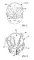
- Figures 2 and 3 are perspective views of first and second centering segments of the feed tube shown Figure 1 .
- Figure 4 is a perspective view of a stationary horizontal cutting head for the apparatus shown Figure 1 .
- Figure 5 is a perspective view showing the cutting apparatus of Figure 1 equipped with a rotating horizontal cutting head in accordance with another embodiment of this invention.
- Figures 6 and 7 are perspective views of alternative embodiments for the feed tube segments shown Figure 2 .
- Figure 8 is a perspective view of a cutting apparatus comprising a sloping feed tube in accordance with a second embodiment of this invention.
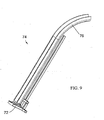
- Figure 9 is a perspective view of an alternative sloping feed tube for the apparatus of Figure 8 .
- Figure 1 shows a cutting apparatus 10 adapted to feed food products to a cutting unit 12 under the force of gravity.
- the apparatus 10 is particularly suited for precutting products, such as coring, sectioning & dicing, etc., to reduce the size of a product so that the product can be possibly accommodated by additional processing equipment.
- products are fed in a vertical direction to the cutting unit 12 through a substantially vertical feed tube 14 that is shown as comprising five tube segments 16, 18, 20, 22 and 24. While five segments 16-24 are depicted, the apparatus 10 could operate with fewer or more tube segments. Any one or more of the segments 16-24 may be hinged (not shown) for ease of cleaning the feed tube 14 and to permit the removal of any products that might become lodged in the tube 14.
- the feed tube 14 is sized such that products are fed single-file to the cutting unit 12.
- the feed tube 14 and the segments 16-24 are shown as having round cross-sections, the cross-sectional shapes of the tube 14 and its individual segments 16-24 could be adapted to have a variety of cross-sectional shapes suitable for different food products.
- the cutting unit 12 is represented as comprising a housing 26 on which two horizontal cutting heads (an example of which is shown in Figure 4 ) can be individually mounted on a sled 28.
- a mounting station 29 for receiving a cutting head is visible in Figure 1 as an opening in the sled 28.
- a second mounting station for a second cutting head is not visible in Figure 1 as a result of being positioned beneath the feed tube 14 to perform a cutting operation on products dropping down through the feed tube 14.
- the cutting heads are mounted on the sled 28 to permit uninterrupted changeover, such as when a head requires replacement or a different cut is required.
- Moving the sled 28 leftward causes a cutting head positioned on the mounting station beneath the feed tube 14 to be displaced leftward, and positions the mounting station 29 visible in Figure 1 beneath the feed tube 14.
- Various techniques can be used to move the sled 28, including automated and manual techniques known in the art.
- FIG 4 shows a suitable cutting head 30 for use with the apparatus 10 of this invention.
- the head 30 is represented as comprising an annular mounting ring 32 that supports a stationary three-bladed knife 34 whose blades are preferably thin and tensioned for rigidity.
- the blades of the knife 34 are double beveled to reduce the likelihood that products will become lodged in the cutting head 30.
- the knife 34 is preferably installed to lie in a plane approximately transverse to the axis of the feed tube 14 so that the blades of the knife 34 pass longitudinally through food products that have free- fallen through the feed tube 14. While a three-bladed knife 34 is depicted in Figure 4 , many other knife configurations could be used depending on desired operation, e.g., coring, dicing, etc.
- Figure 5 represents a rotary cutting wheel 48 that may be used in place of the stationary knife 34 of Figure 4 to slice products horizontally as the products leave the tube 14.
- a suitable wheel for this purpose is disclosed in commonly-assigned U.S. Patent No. 6,460,444 .
- the cutting wheel 48 may also be used in combination with a stationary knife (e.g., 34 of Figure 4 ) mounted in the sled 28, with the cutting wheel 48 mounted immediately below the cutting head 30 such that products vertically sectioned by the stationary knife 34 are immediately transversely sliced by the cutting wheel 48 to yield a processed product that is ready for packaging.
- a stationary knife e.g., 34 of Figure 4
- the cutting wheel 48 is preferably disposed a distance from the stationary knife 34 a distance of at least equal to the diameters of the food products being processed in order to promote product feed-through.
- various other secondary devices could be positioned directly beneath the feed tube 14 or the cutting unit 12, such as to create other dimensional cuts (e.g., dicing cuts) or to move the processed products, e.g., a pneumatic plunger that pushes the processed products horizontally.
- the tube segments 16, 18, 20, 22 and 24 are stacked on top of each other to construct the feed tube 14.
- a suitable overall height for the feed tube 14 has been found to be about six feet, though it is foreseeable that shorter and taller feed tubes 14 could be successfully used It can be appreciated that the height of the feed tube 14 must be sufficient to enable food products to gain enough vertical velocity to pass completely through the cutting head 30, and that the size and shape of the products and the configuration of the cutting head 30 will influence the height of the feed tube 14 required for this purpose.
- the feed tube 14 can also slope, i.e., inclined from vertical, such as at an angle of about thirty degrees from vertical, yet still enable food products to achieve sufficient velocity for proper operation of the apparatus 10.
- the segments 16, 20 and 24 are equipped with a device 36 ( Figures 2 and 3 ) for contacting and positioning food products at or near the central axis of the tube 14 as the products free-fall under the force of gravity toward the cutting unit 12.
- a device 36 Figures 2 and 3
- the axes of the food products can be aligned with the point at which the blades of the knife 34 converge so as to yield food product sections of approximately equal size and shape.
- the tube segments 18 and 22 are preferably not equipped with a positioning device 36, as it has been demonstrated that improved centering of food products occurs if positioning devices 36 are spaced vertically apart so that the products are allowed to drop freely between adjacent "centering" segments 16, 20 and 24 in order to regain speed and stability. While an optimum distance that a product is allowed to free-fall between centering segments 16, 20 and 24 will presumably depend on the size and weight of the product, suitable results have been obtained by sizing the "non-centering" segments 18 and 22 so that the positioning devices 36 of the segments 16, 20 and 24 are vertically spaced about one to two feet (about 30 to 60 cm) apart.
- Figure 2 is an isolated view of one of the tube segments 16 and 20 of Figure 1 .
- the positioning device 36 of the segment 16/20 is represented in Figure 2 as comprising a number of flat metal springs 38 that project radially inward and in a downward direction toward the central axis of the segment 16/20.
- the springs 38 are sufficiently resilient to deflect downward as food products drop down through the interior of the segment 16/20.
- the distal ends of the springs 38 define an opening 40 that is smaller than the products to be processed with the apparatus 10, so that an individual product is continuously contacted by more than one spring 38 as the product drops through the segment 16/20, with the effect that the product generally becomes oriented with its major (longitudinal) axis aligned substantially vertically with the central axis of the segment 16/20.
- the springs 38 are arranged in two rows along the perimeter of the segment 16/20, with the springs 38 in the upper row being circumferentially offset from the springs 38 in the lower row.
- the vertical spacing of the rows of springs 38 is preferably such that the product dropping through the segment 16/20 is simultaneously contacted by springs 38 of both rows at some point as the product drops through the segment 16/20.
- Springs 38 arranged as shown in Figure 2 and formed of a spring steel have been demonstrated to provide a suitable centering effect. However, it is foreseeable that flat metal springs having a variety of different shapes, spacings, etc. could be used.
- the springs 38 could be adjustably mounted to the segment 16/20 so that the distance the springs 38 extend into the segment interior, as well as the rigidity of the springs 38, can be tailored for the particular product.
- Figure 3 is an isolated view of the lowermost tube segment 24 in Figure 1 .
- the positioning device 36 of the segment 24 comprises a number of cylindrically-shaped springs 42 formed of plastic, though metal round wire could also be used.
- the plastic springs 42 extend into the interior of the segment 24 at a downward angle so that the springs 42 must deflect downward to allow food products to drop down through the segment 24.
- the springs 42 are represented as being arranged in three circumferential rows and, in contrast to Figure 2 , vertically aligned columns.
- the distal ends of the springs 42 define an opening 44 that is sufficiently small so that a product is continuously contacted by more than one spring 42 as it drops through the segment 24, and the product is simultaneously contacted by springs 42 of adjacent rows at some point as the product free-falls through the segment 24, again with the result that the product is oriented with its major axis aligned substantially vertically with the axis of the segment 24.
- the springs 42 are shown as being secured to the segment 24 with blocks 46 that enable adjustment of the distance that each spring 42 projects into the interior of the segment 24, thereby adjusting the diameter of the opening 44 and the rigidity of the springs 42.
- segment design may depend on the type of food products being handled. While Figure 1 shows both flat metal and round plastic springs 38 and 42 used in the same apparatus 10, it is foreseeable that only one type of spring 38 or 42 would be used, and such springs could be formed of various materials. In addition, the number of segments equipped with a positioning device 36 could vary. For example, Figure 6 shows an embodiment in which flat metal springs 38 are located along only about one-half of the circumference of a tube segment 16/20, such that the opening 40 through which the products drop is located along the wall of the segment 16/20. As a result, food products are urged into contact with the inner wall surface of the feed tube 14 as they drop, instead of being forced away from the wall surface and centered along the central axis of the tube 14.
- Figure 7 represents a tube segment 58 modified to include a diametrical planar partition 56, thereby defining a semicircular passage 60 through which the products drop. Though shown as located at a diametrical chord of the tube segment 58, the partition 56 could be positioned elsewhere within the segment 58 to achieve a generally semicircular-shaped passage 60. Alternatively, the cross-sectional shape of the segment 58 could be modified to have the desired semicircular cross-sectional shape for positioning and orienting halved food products as they pass through the segment 58.
- the partition 56 (as a separate element added to the tube segment 58 or as an integral wall portion of a semicircular-shaped tube segment) serves as a device for contacting a planar surface of a food product so as to orient and position the food product as it free-falls under the force of gravity toward the cutting unit 12.
- the feed tube 14 of segments 58 of the type shown in Figure 7 food products dropping through the tube 14 are not centered relative to the axis of the tube 14, but instead are positioned at a location within the cross-section of the feed tube 14 that is predetermined by the location of the partitions 56 within the segments 58.
- a cutting apparatus 50 is represented as having a feed tube 54 that is inclined from vertical, such as at an angle of about thirty degrees from vertical at a point where the tube 54 interfaces with a cutting unit 52.
- the tube 54 is represented as having a rectilinear cross-sectional shape, with a lower planar wall 66 of the tube 54 serving to contact a planar surface of a food product so as to orient and position the food product as it free-falls under the force of gravity toward the cutting unit 52.
- the cutting unit 52 is represented as comprising a rotary cutting unit 53 (e.g., containing the cutting wheel 48 of Figure 5 ) that operates in a plane roughly transverse to the axis of the feed tube 54, and a stationary cutting unit 55 (e.g., containing the stationary knife 34 of Figure 4 ) above the rotary cutting unit 53 for the purpose of making longitudinal cuts through the food products before they undergo transverse slicing with the rotary cutting unit 53.
- the cutting wheel 48 could be oriented at an angle other than ninety degrees to the axis of the tube 54 for the purpose of making bias cuts.
- the embodiment of Figure 8 is equipped with springs 38 or 42 in accordance with previous embodiments to help stabilize the food products during descent.
- the apparatus 50 may be equipped with water jets in accordance with WO 03/066290 for the purpose of product stabilization.
- Figure 9 depicts an alternative configuration for a feed passage 74 for use with the apparatus 50 of Figure 8 .
- the feed passage 74 is defined by a generally U-shaped or V-shaped trough 76.
- the shape of the trough 76 is designed to provide continuous contact with food products falling single-file within the trough 76 toward a cutting unit 72 (represented in Figure 9 as being of the type equipped with stationary knives) such that the food products are properly positioned and oriented relative to the cutting unit 72.
- the cutting unit (particularly the Cutting wheel 48) can be oriented at an angle other than ninety degrees to the axes of the tubes 14, 54 and 74 for the purpose of making bias cuts, and the physical configurations of the cutting apparatuses could differ form those shown. Therefore, the scope of the invention is to be limited only by the following claims.
Landscapes
- Life Sciences & Earth Sciences (AREA)
- Forests & Forestry (AREA)
- Engineering & Computer Science (AREA)
- Mechanical Engineering (AREA)
- Formation And Processing Of Food Products (AREA)
- Food-Manufacturing Devices (AREA)
- Perforating, Stamping-Out Or Severing By Means Other Than Cutting (AREA)
- Confectionery (AREA)
Abstract
Description
- The present invention generally relates to cutting methods and equipment. More particularly, this invention relates to a method and apparatus for delivering food product to a cutting device having a horizontal cutting plane, by which the product is properly oriented and stabilized to produce a sliced product of uniform thickness.
- Various types of equipment are known for slicing, shredding and granulating food products such as vegetables, fruits and meat products, A particular example is slicing equipment adapted for cutting root vegetables, such as potatoes, into thin slices suitable for making potato chips (also known as potato crisps). A widely used machine for this purpose is commercially available from the assignee of the present invention under the name Urschel Model CC. The Model CC is a centrifugal-type slicer capable of producing uniform slices, strip cuts, shreds and granulations of a wide variety of food products at high production capabilities. The centrifugal operation of the Model CC does not provide for orienting an elongate product so that its longitudinal axis is perpendicular to the cutting blades. Therefore, when used to produce potato slices for potato chips, the Model CC requires the use of substantially round potatoes in order to produce the desired circular chip
U.S. Patent No. 5,241,902 to Gangi . More particularly, Gangi discloses a food product cutting apparatus comprising: cutting means having at least one cutting element, a feed passage above the cutting means, the feed passage being of sufficient height to enable food products to individually free-fall through the feed passage and then free-fall through the cutting means entirely under the force of gravity and means disposed in the feed passage so as to contact the food products and position the food products so that the food products free-fall on the path at a predetermined location within a cross-section of the feed passage as the food products free-fall through the feed passage prior to encountering the cutting means and continue to free-fall through the cutting means so as to produce size-reduced products of substantially consistent size and shape. However, the apparatus taught by Gangi is adapted to section fruit that has been cored, such that the product has a core hole that passes through centre of the product. Proper orientation of the product during sectioning relies on an inner guide shaft sized to be received in the core hole of a product as the product drops down through an annular-shaped passage defined by and between the inner guide and an outer guide that circumscribes the inner guide. The product engages multiple vertical rotary cutting blades during its fall to produce a sectioned product. The preambles ofClaims 1 and 10 are based upon this disclosure. -
WO 03/066290 WO 03/066290 - According to a first aspect of the present invention, there is provided a food cutting apparatus as claimed in claim 1.
- According to a second aspect of the present invention, there is provided a method of cutting food products as claimed in
claim 10. - Preferred embodiments are described in the dependent claims.
-
Figure 1 is a perspective view of a cutting apparatus comprising a vertical feed tube and a horizontal cutting head in accordance with a first embodiment of this invention. -
Figures 2 and 3 are perspective views of first and second centering segments of the feed tube shownFigure 1 . -
Figure 4 is a perspective view of a stationary horizontal cutting head for the apparatus shownFigure 1 . -
Figure 5 is a perspective view showing the cutting apparatus ofFigure 1 equipped with a rotating horizontal cutting head in accordance with another embodiment of this invention. -
Figures 6 and 7 are perspective views of alternative embodiments for the feed tube segments shownFigure 2 . -
Figure 8 is a perspective view of a cutting apparatus comprising a sloping feed tube in accordance with a second embodiment of this invention. -
Figure 9 is a perspective view of an alternative sloping feed tube for the apparatus ofFigure 8 . -
Figure 1 shows acutting apparatus 10 adapted to feed food products to acutting unit 12 under the force of gravity. Theapparatus 10 is particularly suited for precutting products, such as coring, sectioning & dicing, etc., to reduce the size of a product so that the product can be possibly accommodated by additional processing equipment. As theapparatus 10 is depicted inFigure 1 , products are fed in a vertical direction to thecutting unit 12 through a substantiallyvertical feed tube 14 that is shown as comprising fivetube segments apparatus 10 could operate with fewer or more tube segments. Any one or more of the segments 16-24 may be hinged (not shown) for ease of cleaning thefeed tube 14 and to permit the removal of any products that might become lodged in thetube 14. Thefeed tube 14 is sized such that products are fed single-file to thecutting unit 12. In addition, while thefeed tube 14 and the segments 16-24 are shown as having round cross-sections, the cross-sectional shapes of thetube 14 and its individual segments 16-24 could be adapted to have a variety of cross-sectional shapes suitable for different food products. - The
cutting unit 12 is represented as comprising ahousing 26 on which two horizontal cutting heads (an example of which is shown inFigure 4 ) can be individually mounted on asled 28. Amounting station 29 for receiving a cutting head is visible inFigure 1 as an opening in thesled 28. A second mounting station for a second cutting head is not visible inFigure 1 as a result of being positioned beneath thefeed tube 14 to perform a cutting operation on products dropping down through thefeed tube 14. The cutting heads are mounted on thesled 28 to permit uninterrupted changeover, such as when a head requires replacement or a different cut is required. Moving the sled 28 leftward (as viewed inFigure 1 ) causes a cutting head positioned on the mounting station beneath thefeed tube 14 to be displaced leftward, and positions themounting station 29 visible inFigure 1 beneath thefeed tube 14. Various techniques can be used to move thesled 28, including automated and manual techniques known in the art. -
Figure 4 shows asuitable cutting head 30 for use with theapparatus 10 of this invention. Thehead 30 is represented as comprising anannular mounting ring 32 that supports a stationary three-bladed knife 34 whose blades are preferably thin and tensioned for rigidity. According to another preferred aspect of this embodiment of the invention, the blades of theknife 34 are double beveled to reduce the likelihood that products will become lodged in thecutting head 30. Finally, theknife 34 is preferably installed to lie in a plane approximately transverse to the axis of thefeed tube 14 so that the blades of theknife 34 pass longitudinally through food products that have free-fallen through thefeed tube 14. While a three-bladed knife 34 is depicted inFigure 4 , many other knife configurations could be used depending on desired operation, e.g., coring, dicing, etc. -
Figure 5 represents arotary cutting wheel 48 that may be used in place of thestationary knife 34 ofFigure 4 to slice products horizontally as the products leave thetube 14. A suitable wheel for this purpose is disclosed in commonly-assignedU.S. Patent No. 6,460,444 . Thecutting wheel 48 may also be used in combination with a stationary knife (e.g., 34 ofFigure 4 ) mounted in thesled 28, with thecutting wheel 48 mounted immediately below thecutting head 30 such that products vertically sectioned by thestationary knife 34 are immediately transversely sliced by thecutting wheel 48 to yield a processed product that is ready for packaging. In such an embodiment, thecutting wheel 48 is preferably disposed a distance from the stationary knife 34 a distance of at least equal to the diameters of the food products being processed in order to promote product feed-through. Alternatively or in addition to thecutting wheel 48, various other secondary devices could be positioned directly beneath thefeed tube 14 or thecutting unit 12, such as to create other dimensional cuts (e.g., dicing cuts) or to move the processed products, e.g., a pneumatic plunger that pushes the processed products horizontally. - As evident from
Figure 1 , thetube segments feed tube 14. In practice, a suitable overall height for thefeed tube 14 has been found to be about six feet, though it is foreseeable that shorter andtaller feed tubes 14 could be successfully used It can be appreciated that the height of thefeed tube 14 must be sufficient to enable food products to gain enough vertical velocity to pass completely through thecutting head 30, and that the size and shape of the products and the configuration of thecutting head 30 will influence the height of thefeed tube 14 required for this purpose. Furthermore, as will be discussed in reference toFigure 8 , thefeed tube 14 can also slope, i.e., inclined from vertical, such as at an angle of about thirty degrees from vertical, yet still enable food products to achieve sufficient velocity for proper operation of theapparatus 10. - According to a preferred aspect of the embodiment of
Figure 1 , thesegments Figures 2 and 3 ) for contacting and positioning food products at or near the central axis of thetube 14 as the products free-fall under the force of gravity toward thecutting unit 12. In this manner, if thestationary knife 34 ofFigure 4 is employed, the axes of the food products can be aligned with the point at which the blades of theknife 34 converge so as to yield food product sections of approximately equal size and shape. Thetube segments positioning device 36, as it has been demonstrated that improved centering of food products occurs ifpositioning devices 36 are spaced vertically apart so that the products are allowed to drop freely between adjacent "centering"segments centering segments segments positioning devices 36 of thesegments -
Figure 2 is an isolated view of one of thetube segments Figure 1 . Thepositioning device 36 of thesegment 16/20 is represented inFigure 2 as comprising a number offlat metal springs 38 that project radially inward and in a downward direction toward the central axis of thesegment 16/20. Thesprings 38 are sufficiently resilient to deflect downward as food products drop down through the interior of thesegment 16/20. The distal ends of thesprings 38 define anopening 40 that is smaller than the products to be processed with theapparatus 10, so that an individual product is continuously contacted by more than onespring 38 as the product drops through thesegment 16/20, with the effect that the product generally becomes oriented with its major (longitudinal) axis aligned substantially vertically with the central axis of thesegment 16/20. As seen inFigure 2 , thesprings 38 are arranged in two rows along the perimeter of thesegment 16/20, with thesprings 38 in the upper row being circumferentially offset from thesprings 38 in the lower row. The vertical spacing of the rows ofsprings 38 is preferably such that the product dropping through thesegment 16/20 is simultaneously contacted bysprings 38 of both rows at some point as the product drops through thesegment 16/20.Springs 38 arranged as shown inFigure 2 and formed of a spring steel have been demonstrated to provide a suitable centering effect. However, it is foreseeable that flat metal springs having a variety of different shapes, spacings, etc. could be used. In addition, thesprings 38 could be adjustably mounted to thesegment 16/20 so that the distance thesprings 38 extend into the segment interior, as well as the rigidity of thesprings 38, can be tailored for the particular product. -
Figure 3 is an isolated view of thelowermost tube segment 24 inFigure 1 . Instead of the flat metal springs 38 ofFigure 2 , thepositioning device 36 of thesegment 24 comprises a number of cylindrically-shapedsprings 42 formed of plastic, though metal round wire could also be used. As with the flat metal springs 38 ofFigure 2 , the plastic springs 42 extend into the interior of thesegment 24 at a downward angle so that thesprings 42 must deflect downward to allow food products to drop down through thesegment 24. Thesprings 42 are represented as being arranged in three circumferential rows and, in contrast toFigure 2 , vertically aligned columns. Similar to the metal springs 38 ofFigure 2 , the distal ends of thesprings 42 define anopening 44 that is sufficiently small so that a product is continuously contacted by more than onespring 42 as it drops through thesegment 24, and the product is simultaneously contacted bysprings 42 of adjacent rows at some point as the product free-falls through thesegment 24, again with the result that the product is oriented with its major axis aligned substantially vertically with the axis of thesegment 24. Thesprings 42 are shown as being secured to thesegment 24 withblocks 46 that enable adjustment of the distance that eachspring 42 projects into the interior of thesegment 24, thereby adjusting the diameter of theopening 44 and the rigidity of thesprings 42. - The choice of segment design (
segments Figure 1 shows both flat metal and round plastic springs 38 and 42 used in thesame apparatus 10, it is foreseeable that only one type ofspring positioning device 36 could vary. For example,Figure 6 shows an embodiment in which flat metal springs 38 are located along only about one-half of the circumference of atube segment 16/20, such that theopening 40 through which the products drop is located along the wall of thesegment 16/20. As a result, food products are urged into contact with the inner wall surface of thefeed tube 14 as they drop, instead of being forced away from the wall surface and centered along the central axis of thetube 14. - As another alternative, springs can be entirely omitted from the
feed tube 14, such that products are in uninterrupted free-fall through thefeed tube 14. One application for such an apparatus is halved products, e.g., melons. For this purpose,Figure 7 represents atube segment 58 modified to include a diametricalplanar partition 56, thereby defining asemicircular passage 60 through which the products drop. Though shown as located at a diametrical chord of thetube segment 58, thepartition 56 could be positioned elsewhere within thesegment 58 to achieve a generally semicircular-shapedpassage 60. Alternatively, the cross-sectional shape of thesegment 58 could be modified to have the desired semicircular cross-sectional shape for positioning and orienting halved food products as they pass through thesegment 58. In either case, the partition 56 (as a separate element added to thetube segment 58 or as an integral wall portion of a semicircular-shaped tube segment) serves as a device for contacting a planar surface of a food product so as to orient and position the food product as it free-falls under the force of gravity toward the cuttingunit 12. As a result of constructing thefeed tube 14 ofsegments 58 of the type shown inFigure 7 , food products dropping through thetube 14 are not centered relative to the axis of thetube 14, but instead are positioned at a location within the cross-section of thefeed tube 14 that is predetermined by the location of thepartitions 56 within thesegments 58. - In
Figure 8 , a cuttingapparatus 50 is represented as having afeed tube 54 that is inclined from vertical, such as at an angle of about thirty degrees from vertical at a point where thetube 54 interfaces with a cuttingunit 52. Thetube 54 is represented as having a rectilinear cross-sectional shape, with a lowerplanar wall 66 of thetube 54 serving to contact a planar surface of a food product so as to orient and position the food product as it free-falls under the force of gravity toward the cuttingunit 52. The cuttingunit 52 is represented as comprising a rotary cutting unit 53 (e.g., containing thecutting wheel 48 ofFigure 5 ) that operates in a plane roughly transverse to the axis of thefeed tube 54, and a stationary cutting unit 55 (e.g., containing thestationary knife 34 ofFigure 4 ) above therotary cutting unit 53 for the purpose of making longitudinal cuts through the food products before they undergo transverse slicing with therotary cutting unit 53. Optionally, thecutting wheel 48 could be oriented at an angle other than ninety degrees to the axis of thetube 54 for the purpose of making bias cuts. The embodiment ofFigure 8 is equipped withsprings apparatus 50 may be equipped with water jets in accordance withWO 03/066290 - Finally,
Figure 9 depicts an alternative configuration for afeed passage 74 for use with theapparatus 50 ofFigure 8 . Thefeed passage 74 is defined by a generally U-shaped or V-shapedtrough 76. In accordance with previous embodiments of the invention, the shape of thetrough 76 is designed to provide continuous contact with food products falling single-file within thetrough 76 toward a cutting unit 72 (represented inFigure 9 as being of the type equipped with stationary knives) such that the food products are properly positioned and oriented relative to the cuttingunit 72. - While the invention has been described in terms of preferred embodiments, it is apparent that other forms could be adopted by one skilled in the art. For example, the cutting unit (particularly the Cutting wheel 48) can be oriented at an angle other than ninety degrees to the axes of the
tubes
Claims (14)
- A food product cutting apparatus (10, 50) comprising:a feed passage (14, 54) disposed above a cutting means (30, 48) wherein the cutting means (30, 48) comprise either multiple stationary blades (34) being configured and oriented for making substantially longitudinal cuts through falling food products; ora rotatable cutting wheel (48) being configured and oriented for making transverse cuts through falling food products;the feed passage (14, 54) being of sufficient height to enable food products to individually free-fall through the feed passage (14, 54) and then free-fall through the cutting means (30, 48) entirely under the force of gravity; and food product contacting and positioning means (36, 56) disposed in the feed passage (14, 54) so as to contact the food products and position the food products so that the food products free-fall on the path at a predetermined location within a cross-section of the feed passage (14, 54) as the food products free-fall through the feed passage (14, 54) prior to encountering the cutting means (30, 48) and continue to free-fall through the cutting means (30, 48) so as to produce size-reduced products of substantially consistent size and shape; the apparatus characterised by said food product contacting and positioning means (36, 56) comprising either a plurality of resilient members (38, 42) extending radially inwardly into the feed passage (14) toward a central axis thereof or planar partition (56) defining a generally semicircular-shaped passage (60); wherein said food product contacting and positioning means (36, 56) is arranged to contact only outer peripheries of the food products as they free-fall through the feed passage (14, 54).
- The food product cutting apparatus (10, 50) according to claim 1, wherein the cutting means (30, 48) comprises both the
multiple stationary blades (34) and
the rotatable cutting wheel (48) rotatable in a plane beneath the multiple stationary blades (34). - A food product cutting apparatus (10, 50) according to claim 2, wherein the rotatable cutting wheel (48) is disposed from the multiple stationary blades (34) a distance of at least equal to a diameter of the food products.
- A food product cutting apparatus (10) according to any preceding claim, wherein the feed passage (14) and the path therein are oriented substantially vertically.
- A food product cutting apparatus (10) according to claim 4, wherein the resilient members (38, 42) are arranged in sets (36) spaced vertically apart along the feed passage (14) so that the food products drop freely between adjacent sets (36) of resilient members (38, 42) in order to regain speed and stability, and the resilient members (38, 42) of each set (36) are uniformly distributed along an inner perimeter of the feed passage (14) so as to center the food products passing therethrough at the central axis of the feed passage (14).
- A food product cutting apparatus (50) according to any of claims 1 to 5, wherein the feed passage (54) and the path therein are inclined from vertical.
- A food product cutting apparatus (50) according to claim 6, wherein the feed passage (54) and the path therein are oriented at an angle of about 30 degrees from vertical.
- A food product cutting apparatus (50) according to claim 6 or 7, wherein the feed passage (54) has a planar surface (56, 66, 76).
- A food product cutting apparatus (50) according to claim 8, wherein said food product contacting and positioning means (36, 56) comprises the planar surface (56, 66, 76) of the feed passage (54), and the feed passage (54) is oriented so that gravity causes a planar surface of each of the food products to contact the planar surface (56, 66, 76) of the feed passage (54) as the food products pass through the feed passage (54).
- A method of cutting food product, the method comprising the steps of: individually delivering food products to a feed passage (14, 54) above a cutting means (30, 48) wherein the cutting means (30, 48) comprise either multiple stationary blades (34) configured and oriented for making substantially longitudinal cuts through the falling food products; or a rotating cutting wheel (48) being configured and oriented for making substantially transversal cuts through the falling food products; the food products free-falling through the feed passage (14, 54) and then completely free-falling through the cutting means (30, 48) entirely under the force of gravity; the method being characterised by contacting the food products and positioning the food products using food product contacting and positioning means comprising either a plurality of resilient members (38, 42) extending radially inwardly into the feed passage (14, 54) toward a central axis thereof or a planar partition (56) defining a generally semicircular-shaped passage (60) so that they free-fall on the path at a predetermined location within a cross-section of the feed passage (14, 54) as the food products free-fall through the feed passage (14, 54) and prior to encountering the cutting means (30, 48) so as to produce size-reduced products of substantially consistent size and shape, wherein only outer peripheries of the food products are contacted as they free-fall through the feed passage (14, 54).
- A method as claimed in claim 10, comprising both the multiple stationary blades (34) and the rotating cutting wheel (48), the rotating cutting wheel (48) rotating in a plane beneath the multiple stationary blades (34) and then cutting the food products in a transverse direction with the cutting wheel (48), the food products passing completely through the multiple stationary blades (34) before engaging the cutting wheel (48).
- A method as according to claim 10 or 11, wherein the outer peripheries of the food products are contacted by sets (36) of food product contacting and positioning means (38,42) as the food products free-fall through the feed passage (14,54) and the sets (36) food product contacting and positioning means (38,42) are spaced vertically apart from each other so that the food products fall freely between adjacent sets (36) of said contacting and positioning means (38,42) in order to regain speed and stability.
- A method according to any of claims 10 to 12, wherein the feed passage (14,54) and the path therein are oriented substantially vertically and the food contacting and positioning means (38,42) comprises centering the food products at a central axis of the feed passage (14).
- A method according to any of claims 10 to 12, wherein the feed passage (14, 54) and the path therein are inclined from vertical and the feed passage (14,54) has a planar surface (56,66,76) that contacts a planar surface of each of the food products under the force of gravity as the food products pass through the feed passage (54).
Applications Claiming Priority (5)
| Application Number | Priority Date | Filing Date | Title |
|---|---|---|---|
| US31979802P | 2002-12-19 | 2002-12-19 | |
| US319798P | 2002-12-19 | ||
| US10/707,526 US7263923B2 (en) | 2002-12-19 | 2003-12-19 | Food product cutting apparatus and process |
| US707526 | 2003-12-19 | ||
| PCT/US2003/040716 WO2004056540A1 (en) | 2002-12-19 | 2003-12-19 | Food product cutting apparatus and process |
Publications (2)
| Publication Number | Publication Date |
|---|---|
| EP1578570A1 EP1578570A1 (en) | 2005-09-28 |
| EP1578570B1 true EP1578570B1 (en) | 2008-11-26 |
Family
ID=32599671
Family Applications (1)
| Application Number | Title | Priority Date | Filing Date |
|---|---|---|---|
| EP03813811A Expired - Lifetime EP1578570B1 (en) | 2002-12-19 | 2003-12-19 | Food product cutting apparatus and process |
Country Status (8)
| Country | Link |
|---|---|
| US (2) | US7263923B2 (en) |
| EP (1) | EP1578570B1 (en) |
| AT (1) | ATE415258T1 (en) |
| AU (1) | AU2003301173B2 (en) |
| CA (1) | CA2510454C (en) |
| DE (1) | DE60324963D1 (en) |
| ES (1) | ES2316872T3 (en) |
| WO (1) | WO2004056540A1 (en) |
Families Citing this family (12)
| Publication number | Priority date | Publication date | Assignee | Title |
|---|---|---|---|---|
| ITRM20040263A1 (en) * | 2004-05-28 | 2004-08-28 | Turatti Srl | DEVICE OR CUTTER FOR CUTTING IN QUARTERS OF FOOD AND OTHER PRODUCTS. |
| US10380602B2 (en) * | 2005-12-24 | 2019-08-13 | Rich Media Club, Llc | System and method for creation, distribution and tracking of advertising via electronic networks |
| JP2009530126A (en) * | 2006-03-17 | 2009-08-27 | コナグラ フーズ ラム ウエストン,インコーポレイティド | Recessed taper food, method and apparatus for manufacturing such products |
| US7685916B2 (en) * | 2006-09-08 | 2010-03-30 | J. E. Grote Company, Inc. | Product clamp for food slicing machine |
| US8215231B2 (en) * | 2008-06-06 | 2012-07-10 | Whirlpool Corporation | Household food processor with food processing tools |
| US9848631B2 (en) * | 2008-11-07 | 2017-12-26 | Kraft Foods Group Brands Llc | Home-style meat product and method of producing same |
| US9675089B2 (en) * | 2008-11-07 | 2017-06-13 | Kraft Foods Group Brands Llc | Method and apparatus to mechanically reduce food products into irregular shapes and sizes |
| US9629374B2 (en) | 2008-11-07 | 2017-04-25 | Kraft Foods Group Brands Llc | Home-style meat product and method of producing same |
| US10160132B2 (en) * | 2015-09-11 | 2018-12-25 | J.R. Simplot Company | Flow-propelled rotary knife |
| EP3528956B1 (en) * | 2016-10-21 | 2026-03-18 | Urschel Laboratories, Inc. | Size-reduction machines, feed units therefor, and methods of use |
| CN111791288A (en) * | 2020-08-03 | 2020-10-20 | 格瑞果汁工业(天津)有限公司 | A high-efficiency fruit dicing device for fruit juice |
| US20240180225A1 (en) * | 2022-12-06 | 2024-06-06 | Johnson Foods, Inc. | Water-based cutting mechanism for pitted fruit |
Citations (4)
| Publication number | Priority date | Publication date | Assignee | Title |
|---|---|---|---|---|
| US3842727A (en) * | 1971-12-06 | 1974-10-22 | Sunkist Growers Inc | Fruit slicing apparatus |
| US4228963A (en) * | 1979-04-26 | 1980-10-21 | Matsushita Electric Industrial Co., Ltd. | Receptacle for motor-driven food processor |
| US5241902A (en) * | 1993-01-08 | 1993-09-07 | Gangi Joseph C | Machine for cutting fruit into sections |
| WO2003066290A1 (en) * | 2002-02-04 | 2003-08-14 | Urschel Laboratories, Inc. | Method and apparatus for delivering product to a cutting device |
Family Cites Families (19)
| Publication number | Priority date | Publication date | Assignee | Title |
|---|---|---|---|---|
| US1539749A (en) | 1924-12-20 | 1925-05-26 | Eugene H Lederer | Vegetable slicer |
| US2006643A (en) * | 1933-02-15 | 1935-07-02 | Leo Albert | Slicing apparatus |
| US2572770A (en) * | 1949-07-16 | 1951-10-23 | Laurine R Shadduck | Vegetable splitter |
| US2610664A (en) * | 1949-11-14 | 1952-09-16 | Wallace A Thompson | Potato cutter |
| US3217768A (en) * | 1963-02-15 | 1965-11-16 | Lamb Weston Inc | Method of and apparatus for slicing potatoes |
| US3318351A (en) | 1964-07-24 | 1967-05-09 | Great Lakes Stamp & Mfg Co Inc | Slicing machine |
| US4050339A (en) * | 1976-01-07 | 1977-09-27 | Soleri Richard A | Automatic carousel-type meat cutting machine |
| US4397206A (en) | 1980-11-03 | 1983-08-09 | Lan-Elec Limited | Food slicer |
| US4436012A (en) | 1981-11-13 | 1984-03-13 | J. E. Grote Pepp-A-Matic Co., Inc. | Pendulum-type product slicing machine |
| US4644838A (en) * | 1983-09-20 | 1987-02-24 | Rogers Walla-Walla, Inc. | Apparatus for helical cutting of potatoes |
| US4813317A (en) | 1987-04-23 | 1989-03-21 | Urschel Laboratories, Inc. | Rotary slicing machine |
| US4852441A (en) | 1987-07-22 | 1989-08-01 | Frito-Lay, Inc. | Apparatus for slicing food pieces |
| US5038649A (en) | 1989-08-21 | 1991-08-13 | Hoaglin Robert J | Food slicer adapter |
| US5385074A (en) * | 1993-02-23 | 1995-01-31 | Cavendish Farms Limited | Apparatus and method for cutting helically shaped potato pieces |
| US5694824A (en) * | 1994-04-18 | 1997-12-09 | Urschel Laboratories Incorporated | Cutting head for slicing a food product |
| DE759837T1 (en) * | 1994-05-31 | 1999-05-06 | Urschel Laboratories, Inc., Valparaiso, Ind. | Rotary device for cutting a food |
| GB2290946B (en) | 1994-07-09 | 1998-02-25 | Gerald Goldstein | An attachment for a food slicer |
| WO1999023893A1 (en) | 1997-11-12 | 1999-05-20 | Chippery Potato Chip Factory, Inc. | Method and apparatus for frying potato chips and related foodstuffs |
| WO2003101686A2 (en) * | 2002-06-04 | 2003-12-11 | Urschel Laboratories, Inc. | Apparatus for cutting food product |
-
2003
- 2003-12-19 EP EP03813811A patent/EP1578570B1/en not_active Expired - Lifetime
- 2003-12-19 AU AU2003301173A patent/AU2003301173B2/en not_active Expired
- 2003-12-19 ES ES03813811T patent/ES2316872T3/en not_active Expired - Lifetime
- 2003-12-19 US US10/707,526 patent/US7263923B2/en not_active Expired - Lifetime
- 2003-12-19 DE DE60324963T patent/DE60324963D1/en not_active Expired - Lifetime
- 2003-12-19 CA CA 2510454 patent/CA2510454C/en not_active Expired - Lifetime
- 2003-12-19 WO PCT/US2003/040716 patent/WO2004056540A1/en not_active Ceased
- 2003-12-19 AT AT03813811T patent/ATE415258T1/en not_active IP Right Cessation
-
2007
- 2007-04-03 US US11/695,637 patent/US20070227325A1/en not_active Abandoned
Patent Citations (4)
| Publication number | Priority date | Publication date | Assignee | Title |
|---|---|---|---|---|
| US3842727A (en) * | 1971-12-06 | 1974-10-22 | Sunkist Growers Inc | Fruit slicing apparatus |
| US4228963A (en) * | 1979-04-26 | 1980-10-21 | Matsushita Electric Industrial Co., Ltd. | Receptacle for motor-driven food processor |
| US5241902A (en) * | 1993-01-08 | 1993-09-07 | Gangi Joseph C | Machine for cutting fruit into sections |
| WO2003066290A1 (en) * | 2002-02-04 | 2003-08-14 | Urschel Laboratories, Inc. | Method and apparatus for delivering product to a cutting device |
Also Published As
| Publication number | Publication date |
|---|---|
| ATE415258T1 (en) | 2008-12-15 |
| AU2003301173B2 (en) | 2007-08-02 |
| DE60324963D1 (en) | 2009-01-08 |
| CA2510454C (en) | 2008-11-18 |
| EP1578570A1 (en) | 2005-09-28 |
| US20070227325A1 (en) | 2007-10-04 |
| AU2003301173A1 (en) | 2004-07-14 |
| US7263923B2 (en) | 2007-09-04 |
| ES2316872T3 (en) | 2009-04-16 |
| CA2510454A1 (en) | 2004-07-08 |
| WO2004056540A1 (en) | 2004-07-08 |
| US20040118259A1 (en) | 2004-06-24 |
Similar Documents
| Publication | Publication Date | Title |
|---|---|---|
| US20070227325A1 (en) | Food product cutting process and apparatus | |
| US9521861B2 (en) | Fruit chunking and spear forming apparatus | |
| US4648296A (en) | Method and apparatus for feeding slicers | |
| EP0457068B1 (en) | Fruit cutting device and method | |
| US20090202694A1 (en) | Apparatus and method for slicing vegetables | |
| EP2900438B1 (en) | Tailored slicing | |
| US7513450B2 (en) | Cutter assembly with s-shaped blade | |
| US6973862B2 (en) | Method and apparatus for delivering product to a cutting device | |
| EP0366650A1 (en) | Decorative form hydraulic cutting blade assembly. | |
| EP0693348A1 (en) | Vegetable cutting system | |
| AU2022307036B2 (en) | Impellers for cutting machines and cutting machines equipped with impellers | |
| US4129068A (en) | Citrus slicing apparatus | |
| US6220153B1 (en) | Automated peeler for fruit products | |
| CA3146021A1 (en) | Hydro-mechanical cutter | |
| US2223542A (en) | Food dicing apparatus | |
| MXPA04007531A (en) | Method and apparatus for delivering product to a cutting device. | |
| US11207793B2 (en) | Hydro-mechanical cutter | |
| EP2900439B1 (en) | Apparatus for cutting potato slices, and method of manufacturing potato chips | |
| EP3996887A1 (en) | Hydro-mechanical cutter |
Legal Events
| Date | Code | Title | Description |
|---|---|---|---|
| PUAI | Public reference made under article 153(3) epc to a published international application that has entered the european phase |
Free format text: ORIGINAL CODE: 0009012 |
|
| 17P | Request for examination filed |
Effective date: 20050715 |
|
| AK | Designated contracting states |
Kind code of ref document: A1 Designated state(s): AT BE BG CH CY CZ DE DK EE ES FI FR GB GR HU IE IT LI LU MC NL PT RO SE SI SK TR |
|
| AX | Request for extension of the european patent |
Extension state: AL LT LV MK |
|
| DAX | Request for extension of the european patent (deleted) | ||
| 17Q | First examination report despatched |
Effective date: 20051031 |
|
| 17Q | First examination report despatched |
Effective date: 20051031 |
|
| GRAP | Despatch of communication of intention to grant a patent |
Free format text: ORIGINAL CODE: EPIDOSNIGR1 |
|
| GRAS | Grant fee paid |
Free format text: ORIGINAL CODE: EPIDOSNIGR3 |
|
| GRAA | (expected) grant |
Free format text: ORIGINAL CODE: 0009210 |
|
| AK | Designated contracting states |
Kind code of ref document: B1 Designated state(s): AT BE BG CH CY CZ DE DK EE ES FI FR GB GR HU IE IT LI LU MC NL PT RO SE SI SK TR |
|
| REG | Reference to a national code |
Ref country code: GB Ref legal event code: FG4D |
|
| REG | Reference to a national code |
Ref country code: CH Ref legal event code: EP |
|
| REG | Reference to a national code |
Ref country code: IE Ref legal event code: FG4D |
|
| REF | Corresponds to: |
Ref document number: 60324963 Country of ref document: DE Date of ref document: 20090108 Kind code of ref document: P |
|
| REG | Reference to a national code |
Ref country code: ES Ref legal event code: FG2A Ref document number: 2316872 Country of ref document: ES Kind code of ref document: T3 |
|
| PG25 | Lapsed in a contracting state [announced via postgrant information from national office to epo] |
Ref country code: AT Free format text: LAPSE BECAUSE OF FAILURE TO SUBMIT A TRANSLATION OF THE DESCRIPTION OR TO PAY THE FEE WITHIN THE PRESCRIBED TIME-LIMIT Effective date: 20081126 |
|
| PG25 | Lapsed in a contracting state [announced via postgrant information from national office to epo] |
Ref country code: FI Free format text: LAPSE BECAUSE OF FAILURE TO SUBMIT A TRANSLATION OF THE DESCRIPTION OR TO PAY THE FEE WITHIN THE PRESCRIBED TIME-LIMIT Effective date: 20081126 Ref country code: SI Free format text: LAPSE BECAUSE OF FAILURE TO SUBMIT A TRANSLATION OF THE DESCRIPTION OR TO PAY THE FEE WITHIN THE PRESCRIBED TIME-LIMIT Effective date: 20081126 |
|
| PG25 | Lapsed in a contracting state [announced via postgrant information from national office to epo] |
Ref country code: RO Free format text: LAPSE BECAUSE OF FAILURE TO SUBMIT A TRANSLATION OF THE DESCRIPTION OR TO PAY THE FEE WITHIN THE PRESCRIBED TIME-LIMIT Effective date: 20081126 Ref country code: DK Free format text: LAPSE BECAUSE OF FAILURE TO SUBMIT A TRANSLATION OF THE DESCRIPTION OR TO PAY THE FEE WITHIN THE PRESCRIBED TIME-LIMIT Effective date: 20081126 Ref country code: BG Free format text: LAPSE BECAUSE OF FAILURE TO SUBMIT A TRANSLATION OF THE DESCRIPTION OR TO PAY THE FEE WITHIN THE PRESCRIBED TIME-LIMIT Effective date: 20090226 Ref country code: EE Free format text: LAPSE BECAUSE OF FAILURE TO SUBMIT A TRANSLATION OF THE DESCRIPTION OR TO PAY THE FEE WITHIN THE PRESCRIBED TIME-LIMIT Effective date: 20081126 Ref country code: MC Free format text: LAPSE BECAUSE OF NON-PAYMENT OF DUE FEES Effective date: 20081231 |
|
| REG | Reference to a national code |
Ref country code: CH Ref legal event code: PL |
|
| PG25 | Lapsed in a contracting state [announced via postgrant information from national office to epo] |
Ref country code: CZ Free format text: LAPSE BECAUSE OF FAILURE TO SUBMIT A TRANSLATION OF THE DESCRIPTION OR TO PAY THE FEE WITHIN THE PRESCRIBED TIME-LIMIT Effective date: 20081126 Ref country code: SE Free format text: LAPSE BECAUSE OF FAILURE TO SUBMIT A TRANSLATION OF THE DESCRIPTION OR TO PAY THE FEE WITHIN THE PRESCRIBED TIME-LIMIT Effective date: 20090226 Ref country code: PT Free format text: LAPSE BECAUSE OF FAILURE TO SUBMIT A TRANSLATION OF THE DESCRIPTION OR TO PAY THE FEE WITHIN THE PRESCRIBED TIME-LIMIT Effective date: 20090427 |
|
| PG25 | Lapsed in a contracting state [announced via postgrant information from national office to epo] |
Ref country code: SK Free format text: LAPSE BECAUSE OF FAILURE TO SUBMIT A TRANSLATION OF THE DESCRIPTION OR TO PAY THE FEE WITHIN THE PRESCRIBED TIME-LIMIT Effective date: 20081126 |
|
| PLBE | No opposition filed within time limit |
Free format text: ORIGINAL CODE: 0009261 |
|
| STAA | Information on the status of an ep patent application or granted ep patent |
Free format text: STATUS: NO OPPOSITION FILED WITHIN TIME LIMIT |
|
| PG25 | Lapsed in a contracting state [announced via postgrant information from national office to epo] |
Ref country code: IE Free format text: LAPSE BECAUSE OF NON-PAYMENT OF DUE FEES Effective date: 20081219 Ref country code: CH Free format text: LAPSE BECAUSE OF NON-PAYMENT OF DUE FEES Effective date: 20081231 Ref country code: LI Free format text: LAPSE BECAUSE OF NON-PAYMENT OF DUE FEES Effective date: 20081231 |
|
| 26N | No opposition filed |
Effective date: 20090827 |
|
| PG25 | Lapsed in a contracting state [announced via postgrant information from national office to epo] |
Ref country code: LU Free format text: LAPSE BECAUSE OF NON-PAYMENT OF DUE FEES Effective date: 20081219 Ref country code: CY Free format text: LAPSE BECAUSE OF FAILURE TO SUBMIT A TRANSLATION OF THE DESCRIPTION OR TO PAY THE FEE WITHIN THE PRESCRIBED TIME-LIMIT Effective date: 20081126 Ref country code: HU Free format text: LAPSE BECAUSE OF FAILURE TO SUBMIT A TRANSLATION OF THE DESCRIPTION OR TO PAY THE FEE WITHIN THE PRESCRIBED TIME-LIMIT Effective date: 20090527 |
|
| PG25 | Lapsed in a contracting state [announced via postgrant information from national office to epo] |
Ref country code: TR Free format text: LAPSE BECAUSE OF FAILURE TO SUBMIT A TRANSLATION OF THE DESCRIPTION OR TO PAY THE FEE WITHIN THE PRESCRIBED TIME-LIMIT Effective date: 20081126 |
|
| PG25 | Lapsed in a contracting state [announced via postgrant information from national office to epo] |
Ref country code: GR Free format text: LAPSE BECAUSE OF FAILURE TO SUBMIT A TRANSLATION OF THE DESCRIPTION OR TO PAY THE FEE WITHIN THE PRESCRIBED TIME-LIMIT Effective date: 20090227 |
|
| PG25 | Lapsed in a contracting state [announced via postgrant information from national office to epo] |
Ref country code: IT Free format text: LAPSE BECAUSE OF FAILURE TO SUBMIT A TRANSLATION OF THE DESCRIPTION OR TO PAY THE FEE WITHIN THE PRESCRIBED TIME-LIMIT Effective date: 20081126 |
|
| REG | Reference to a national code |
Ref country code: FR Ref legal event code: PLFP Year of fee payment: 13 |
|
| REG | Reference to a national code |
Ref country code: FR Ref legal event code: PLFP Year of fee payment: 14 |
|
| REG | Reference to a national code |
Ref country code: FR Ref legal event code: PLFP Year of fee payment: 15 |
|
| PGFP | Annual fee paid to national office [announced via postgrant information from national office to epo] |
Ref country code: NL Payment date: 20221117 Year of fee payment: 20 Ref country code: GB Payment date: 20221117 Year of fee payment: 20 Ref country code: FR Payment date: 20221117 Year of fee payment: 20 Ref country code: DE Payment date: 20221118 Year of fee payment: 20 |
|
| PGFP | Annual fee paid to national office [announced via postgrant information from national office to epo] |
Ref country code: BE Payment date: 20221121 Year of fee payment: 20 |
|
| PGFP | Annual fee paid to national office [announced via postgrant information from national office to epo] |
Ref country code: ES Payment date: 20230109 Year of fee payment: 20 |
|
| REG | Reference to a national code |
Ref country code: DE Ref legal event code: R071 Ref document number: 60324963 Country of ref document: DE |
|
| REG | Reference to a national code |
Ref country code: NL Ref legal event code: MK Effective date: 20231218 |
|
| REG | Reference to a national code |
Ref country code: ES Ref legal event code: FD2A Effective date: 20231227 |
|
| REG | Reference to a national code |
Ref country code: GB Ref legal event code: PE20 Expiry date: 20231218 |
|
| PG25 | Lapsed in a contracting state [announced via postgrant information from national office to epo] |
Ref country code: GB Free format text: LAPSE BECAUSE OF EXPIRATION OF PROTECTION Effective date: 20231218 |
|
| REG | Reference to a national code |
Ref country code: BE Ref legal event code: MK Effective date: 20231219 |
|
| PG25 | Lapsed in a contracting state [announced via postgrant information from national office to epo] |
Ref country code: ES Free format text: LAPSE BECAUSE OF EXPIRATION OF PROTECTION Effective date: 20231220 |
|
| PG25 | Lapsed in a contracting state [announced via postgrant information from national office to epo] |
Ref country code: GB Free format text: LAPSE BECAUSE OF EXPIRATION OF PROTECTION Effective date: 20231218 Ref country code: ES Free format text: LAPSE BECAUSE OF EXPIRATION OF PROTECTION Effective date: 20231220 |