EP1578490B1 - System for automatic evoked response sensing vector selection using evoked response waveform analysis - Google Patents
System for automatic evoked response sensing vector selection using evoked response waveform analysis Download PDFInfo
- Publication number
- EP1578490B1 EP1578490B1 EP03778076A EP03778076A EP1578490B1 EP 1578490 B1 EP1578490 B1 EP 1578490B1 EP 03778076 A EP03778076 A EP 03778076A EP 03778076 A EP03778076 A EP 03778076A EP 1578490 B1 EP1578490 B1 EP 1578490B1
- Authority
- EP
- European Patent Office
- Prior art keywords
- sensing
- capture
- signal
- evoked response
- pacing
- Prior art date
- Legal status (The legal status is an assumption and is not a legal conclusion. Google has not performed a legal analysis and makes no representation as to the accuracy of the status listed.)
- Expired - Lifetime
Links
Images


Classifications
-
- A—HUMAN NECESSITIES
- A61—MEDICAL OR VETERINARY SCIENCE; HYGIENE
- A61N—ELECTROTHERAPY; MAGNETOTHERAPY; RADIATION THERAPY; ULTRASOUND THERAPY
- A61N1/00—Electrotherapy; Circuits therefor
- A61N1/18—Applying electric currents by contact electrodes
- A61N1/32—Applying electric currents by contact electrodes alternating or intermittent currents
- A61N1/36—Applying electric currents by contact electrodes alternating or intermittent currents for stimulation
- A61N1/362—Heart stimulators
- A61N1/37—Monitoring; Protecting
- A61N1/371—Capture, i.e. successful stimulation
- A61N1/3712—Auto-capture, i.e. automatic adjustment of the stimulation threshold
Definitions
- the present invention relates to implantable cardiac pacemaking devices and, more specifically, to an implantable pacemaking device for automatically selecting an optimal electrode vector for sensing evoked responses to verify capture.
- Cardiac pacing devices deliver appropriately timed electrical stimulation pulses to a patient's heart to maintain a normal heart rhythm or improve synchronization of heart chambers.
- Patients having bradycardia, abnormalities of the heart's natural conduction system, or heart failure may benefit from artificial cardiac pacing of one or more heart chambers.
- an electrical impulse delivered to the heart must have sufficient energy to depolarize the myocardial cells.
- Depolarization of the myocardial cells in response to a pacing pulse is often referred to as "capture.”
- the cardiac electrogram signal evidencing capture which may be a P-wave in the atria or an R-wave in the ventricles, is generally referred to as an "evoked response.”
- the lowest pacing pulse energy that captures the heart may be referred to as the “pacing threshold” or “capture threshold”.
- the amplitude and duration of a pacing pulse are preferably set to provide a pacing pulse energy somewhat greater than the pacing threshold in order to ensure effective cardiac pacing. However, in order to prolong the battery life of the implanted pacemaking device, it is desirable to program the pacing pulse energy to be a minimum value that is considered safely above the pacing threshold.
- Pacing threshold however can change over time due to fibrotic encapsulation of the pacing electrodes, changes in the patient's clinical condition, changes in medical therapy, lead movement, or other causes.
- a rise in pacing threshold can result in loss of capture and ineffective pacing.
- Modem pacemakers may include automatic pacing threshold search algorithms that automatically adjust the pacing pulse energy to ensure pacing pulses remain above the pacing threshold, even if it varies over time.
- a pacing threshold search may deliver pacing pulses starting at an initially high pulse energy that is greater than the pacing threshold and progressively decrease until capture is lost. The lowest pulse energy at which capture still occurs is determined as the pacing threshold. In order to reliably determine a pacing threshold, the cardiac pacing device must reliably discriminate between capture and loss of capture.
- Evoked response sensing may be to verify capture during pacing threshold searches and during normal cardiac pacing to ensure that effective pacing is provided. If a loss of capture is detected, as evidenced by the absence of an evoked response following a pacing pulse, a back-up pacing pulse of higher energy may be delivered and a pacing threshold search may be triggered to reset the pacing pulse energy.
- False capture detection can result from oversensing of cardiac signals or non-cardiac noise, such as electromagnetic interference or nearby skeletal muscle depolarizations. False capture detections may result in prolonged episodes of subthreshold cardiac pacing that is ineffective in maintaining a base heart rate, which can be detrimental to the patient's health and even fatal. False loss of capture detections can result from undersensing of the evoked response. False loss of capture detections can trigger the delivery of unnecessary backup pacing pulses and pacing threshold searches. Increases pacing pulse energy due to false loss of capture detections can lead to premature pacemaker battery depletion.
- a major difficulty in sensing an evoked response arises from the polarization artifact that immediately follows a pacing pulse.
- Polarization at the electrode-tissue interface causes an afterpotential signal that can saturate sense amplifiers included in the cardiac pacing device and mask an evoked response signal.
- a blanking interval is applied to sense amplifiers during and immediately following a pacing pulse to prevent saturation of the amplifiers.
- the polarization artifact may diminish during the blanking interval, however, it may still interfere with evoked response sensing.
- Low-polarization electrodes have been proposed for reducing the polarization artifact. See for example U.S. Pat. No. 4,502,492, issued to Bomzin , or U.S. Pat. No. 6,430,448, issued to Chitre, et al .
- Such methods may include special hardware circuitry or special software signal processing methods that reduce or eliminate the problem of polarization artifact.
- Capture verification methods indicate when capture or loss of capture occurs, but generally do not indicate the confidence or reliability of the detection based on the quality of the evoked response signal.
- a process to verify capture that involves assessing the reliability of a chosen parameter of an evoked signal as a reliable indication of the response is disclosed in U.S. Pat. No. 5,855,594, issued to Olive, et al .
- EP 1,184,050 also discloses a system for verifying capture based on evoked response signals. The reliability of a sensed parameter will depend largely on the quality of the sensed signal. A sensed parameter that is not reliable for evoked response sensing on one sensing electrode pair may be reliable using another sensing electrode pair.
- Cardiac pacing leads are often configured having a tip electrode and a ring electrode spaced somewhat back from the tip electrode. Bipolar pacing between the tip and ring electrode is often preferred over unipolar pacing between the tip electrode and pacing device housing because bipolar pacing thresholds can be lower than unipolar. Bipolar sensing of intrinsic cardiac P-waves and/or R-waves for monitoring a patient's intrinsic heart rate to determine the need for pacing can also be preferred over unipolar sensing because bipolar sensing can result in a better signal-to-noise ratio.
- Bipolar sensing of intrinsic signals can be improved further by shortening the spacing between a tip electrode and a ring electrode to reduce oversensing of far-field cardiac signals or non-cardiac noise.
- a shorter tip-to-ring spacing can make bipolar evoked response sensing more difficult because the evoked response signal may have already passed the ring electrode by the time the polarization signal has diminished.
- sensing a far-field signal related to an evoked response as opposed to the near-field evoked response signal, or sensing a conducted polarization away from the pacing site has been proposed. See for example, U.S. Pat. No. 5,324,310 issued to Greeninger , U.S. Pat. No. 5,222,493 issued to Sholder , U.S. Pat. No. 5,331,966 issued to Bennett et al ., U.S. Pat. No. 6,434,428 issued to Sloman, et al ., and U.S. Pat. App.
- Electrode switching/selection is generally disclosed in U.S. Pat. No. 4,628,934 issued to Pohndorf et al ., and U.S. Pat. No. 6,085,118 issued to Hirschberg et al .
- the present invention provides an implantable cardiac pacing device as defined in claim 1 for automatically selecting an optimal evoked response sensing vector based on an evaluation of the evoked response signal quality.
- the pacing device preferably includes electrode switching circuitry to enable selection of multiple evoked response sensing vectors.
- the pacing device further includes capture detection circuitry that provides output relating to one or more signal characteristics that may be used for determining one or more evoked response signal quality parameters.
- the capture detection circuitry includes a peak tracking circuit for detecting one or more peak amplitudes of capture and loss of capture signals during a capture detection window. The times at which peak amplitudes occur may also be determined.
- the peak amplitude information is used to determine signal quality parameters, which preferably include at least an evoked response signal-to-noise ratio and an evoked response sensing margin.
- Other signal quality evaluation parameters may be related to a loss of capture sensing margin, early or latent capture detections, and time to evoked response peak amplitude.
- a method for optimizing the evoked response sensing vector is executed when a pacing threshold search is performed in order to validate the result of the pacing threshold search and select an optimal sensing vector for use in capture detection.
- An optimal evoked response sensing vector is determined as a sensing vector for which evoked response signal quality parameters meet predetermined criteria for reliable evoked response sensing. Signal characteristics are determined from capture signals and from loss of capture signals during the pacing threshold search using a default evoked response sensing vector. Signal quality parameters are then determined from the signal characteristics. If the signal quality parameters meet predetermined criteria, the pacing threshold search result is deemed valid and the default sensing vector and sensing threshold may be programmed as the operating evoked response sensing vector and threshold.
- the pacing threshold search result is deemed invalid, and alternative sensing vectors are tested until an acceptable vector is identified. Alternatively, all available sensing vectors may be tested and the vector producing the best signal quality may be selected as the operating evoked response sensing vector during capture verification.
- the device of the present invention therefore, allow the quality of evoked response signals to be evaluated automatically so that evoked response sensing may be optimized.
- Optimized evoked response sensing will allow automatic capture verification operations and pacing threshold search algorithms to perform more reliably, improving overall cardiac pacing device performance and longevity.
- the present invention is directed at providing a cardiac pacing device for automatically selecting an optimal evoked response sensing electrode pair and associated sensing threshold for reliable capture verification.
- the present invention may be implemented in single chamber, dual chamber, or multi-chamber cardiac pacing devices, which may include cardioversion and defibrillation capabilities.
- Figure 1 is a schematic illustration of an implantable pacemaker cardioverter defibrillator (ICD), in which the present invention may be implemented, and an associated cardiac lead that is positioned in the right ventricle of a patient's heart.
- ICD implantable pacemaker cardioverter defibrillator
- FIG. 1 is a schematic illustration of an implantable pacemaker cardioverter defibrillator (ICD), in which the present invention may be implemented, and an associated cardiac lead that is positioned in the right ventricle of a patient's heart.
- ICD implantable pacemaker cardioverter defibrillator
- FIG. 1 is a schematic illustration of an implantable pacemaker cardioverter defi
- a connector block 12 receives the proximal end of a right ventricular lead 16 used for positioning electrodes for sensing right ventricular cardiac signals and delivering pacing or shocking pulses in the right ventricle.
- right ventricular lead 16 is equipped with a ring electrode 24, a tip electrode 26, a right ventricular coil electrode 20 and a superior vena cava (SVC) coil electrode 23, each of which are connected to an insulated conductor within the body of lead 16.
- SVC superior vena cava
- the electrodes 24 and 26 may be used for cardiac pacing as a bipolar pair, commonly referred to as a "tip-to-ring" configuration, or tip electrode 26 may be used in a unipolar configuration with the device housing 11 serving as the indifferent electrode, commonly referred to as the "can" or “case” electrode. Housing 11 may also serve as a subcutaneous defibrillation electrode in combination with one or both of the defibrillation coil electrodes 20 or 23 for delivering cardioversion shocks. In a preferred embodiment of the present invention, electrodes 24, 26, 20, 23 and housing 11 may be selected in any bipolar or unipolar sensing arrangement for sensing evoked responses following the delivery of a pacing pulse.
- Alternative cardiac lead systems may be used in place of the quadrapolar lead shown in Figure 1 .
- Alternative lead systems may include one or more unipolar, bipolar or multipolar leads positioned for sensing and stimulating in any or all of the four heart chambers, depending on the type of device with which the lead system is used.
- FIG. 2 A functional block diagram of the ICD 10 of Figure 1 is shown in Figure 2 .
- This diagram should be taken as exemplary of the type of device with which the invention may be embodied and not as limiting.
- the disclosed embodiment shown in Figure 2 is a microprocessor-controlled device, but the methods of the present invention may also be practiced with other types of devices such as those employing dedicated digital circuitry and/or analog circuitry.
- connection terminals for achieving electrical connection to cardiac lead 16.
- the connection terminal 311 provides electrical connection to the housing 11 for use as the indifferent electrode during unipolar stimulation or sensing.
- the connection terminals 320 and 310 provide electrical connection to coil electrodes 20 and 23 respectively.
- Each of these connection terminals 311, 320, and 310 are coupled to the high voltage output circuit 234 to facilitate the delivery of high energy shocking pulses to the heart using one or both of the coil electrodes 20 and 23 and optionally the housing 11.
- connection terminals 326 and 324 provide electrical connection to tip electrode 26 and ring electrode 24. Terminals 326 and 324 are coupled to sense amplifier 200 for sensing intrinsic cardiac signals.
- the sense amplifier 200 preferably takes the form of automatic gain controlled amplifiers with adjustable sensing thresholds. The general operation of the sense amplifier 200 may correspond to that disclosed in U.S. Pat. No. 5,117,824, by Keimel, et al . Whenever a signal received by the sense amplifier 200 exceeds a ventricular sensing threshold, a signal is generated on the R-out signal line 202.
- each of the connection terminals 311, 310, 320, 324 and 326 are further coupled to switch matrix 208 to allow any of housing 11, RV coil electrode 20, SVC coil electrode 23, tip electrode 26 and/or ring electrode 24 to be selectively connected to capture detection circuit 150 for use in sensing evoked responses for capture verification.
- Capture detection circuit 150 may also include automatic gain controlled amplifiers.
- a control program executed by microprocessor 224, for optimizing the evoked response sensing vector employs capture detection circuit 150 for detecting signal characteristics used in evaluating the evoked response signal quality. An optimal evoked response sensing vector is identified based on signal quality parameters determined from the detected signal characteristics.
- Switch matrix 208 is also used to select which of the available electrodes are coupled to a wide band amplifier 210 for use in digital analysis of sensed, intrinsic cardiac signals. Selection of the electrodes is controlled by the microprocessor 224 via data/address bus 218. The selected electrode configuration may be varied as desired for the various sensing, pacing, cardioversion and defibrillation functions of the ICD 10. Signals from the electrodes selected for coupling to bandpass amplifier 210 are provided to multiplexer 220, and thereafter converted to multi-bit digital signals by A/D converter 222, for storage in random access memory 226 under control of direct memory access circuit 228. Microprocessor 224 may employ digital signal analysis techniques to characterize the digitized signals stored in random access memory 226 to recognize and classify the patient's heart rhythm employing any of the numerous signal processing methodologies known in the art.
- the telemetry circuit 330 receives downlink telemetry from and sends uplink telemetry to an external programmer, as is conventional in implantable anti-arrhythmia devices, by means of an antenna 332. Data to be uplinked to the programmer and control signals for the telemetry circuit 330 are provided by microprocessor 224 via address/data bus 218. Received telemetry is provided to microprocessor 224 via multiplexer 220. Numerous types of telemetry systems known for use in implantable devices may be used.
- messages for display on an external programming device may be generated by microprocessor 224 and uplinked to the programmer via telemetry circuit 330 in order to communicate results of automatic evoked response sensing vector optimization methods.
- electrode optimization methods may determine that capture verification or pacing threshold search results are unreliable due to poor evoked response signal quality. Such information may be displayed in messages to a medical attendant on an external programmer and may include recommendations regarding the programming of automatic capture verification operations.
- the remainder of the circuitry illustrated in FIG. 2 includes circuitry dedicated to providing cardiac pacing, cardioversion and defibrillation therapies.
- the pacer timing and control circuitry 212 includes programmable digital counters which control the basic time intervals associated with various pacing modes or anti-tachycardia pacing therapies delivered in the ventricles. Pacer circuitry 212 also determines the amplitude of the cardiac pacing pulses under the control of microprocessor 224.
- escape interval counters within pacer timing and control circuitry 212 are reset upon sensing of R-waves as indicated by signals on line 202.
- pacing pulses are generated by ventricular pacer output circuit 216.
- the pacer output circuit 216 is coupled to the desired electrodes for pacing via switch matrix 208.
- the escape interval counters are reset upon generation of pacing pulses, and thereby control the basic timing of cardiac pacing functions, including anti-tachycardia pacing.
- the durations of the escape intervals are determined by microprocessor 224 via data/address bus 218.
- the value of the count present in the escape interval counters when reset by sensed R-waves can be used to measure R-R intervals for detecting the occurrence of a variety of arrhythmias.
- the microprocessor 224 includes associated ROM in which stored programs controlling the operation of the microprocessor 224 reside.
- a portion of the random access memory 226 may be configured as a number of recirculating buffers capable of holding a series of measured intervals for analysis by the microprocessor 224 for predicting or diagnosing an arrhythmia.
- anti-tachycardia pacing therapy can be delivered by loading a regimen from microcontroller 224 into the pacer timing and control circuitry 212 according to the type of tachycardia detected.
- microprocessor 224 activates the cardioversion and defibrillation control circuitry 230 to initiate charging of the high voltage capacitors 246 and 248 via charging circuit 236 under the control of high voltage charging control line 240.
- the voltage on the high voltage capacitors 246 and 248 is monitored via a voltage capacitor (VCAP) line 244, which is passed through the multiplexer 220.
- VCAP voltage capacitor
- CF capacitor full
- the defibrillation or cardioversion pulse is delivered to the heart under the control of the pacer timing and control circuitry 212 by high voltage output circuit 234 via a control bus 238.
- the output circuit 234 determines the electrodes used for delivering the cardioversion or defibrillation pulse and the pulse wave shape.
- FIG 3 is a block diagram of circuitry included in capture detection circuit 150 shown in device 10 of Figure 2 .
- Sensing input is received by signal conditioning circuitry 252 from switch matrix 208, which has selected a desired evoked response sensing vector.
- Signal conditioning circuitry 252 may include a preamplifier and peak tracking circuitry.
- Output from signal conditioning circuitry 252 is received by bandpass filter and rectifier 254, which rectifies and filters the sensed signal, preferably with a bandpass frequency range of approximately 20 to 70 Hz.
- An evoked response detector circuit 256 receives the absolute value of the filtered and amplified signal and determines if capture is detected by comparing the signal to an evoked response sensing threshold. If the signal exceeds the sensing threshold, an evoked response sense signal (ER sense) is sent to pacer timing and control 212 which uses this information in controlling general pacing operations. Pacer timing and control may continue to deliver pacing as needed at the programmed pacing pulse energy as long as capture is detected. If pacer timing and control 212 does not receive an ER sense signal from capture detection circuit 150 following delivery of a pacing pulse, a back-up pacing pulse of higher energy may be delivered or pacing threshold search may be initiated.
- ER sense evoked response sense signal
- an ER sense signal from capture detection circuit 150 causes pacer timing and control to generate an interrupt signal, which, in turn, causes microprocessor 224 to issue a time stamp indicating the time at which a capture detection was made.
- Clock cycles counted beginning from test pulse delivery to the time of evoked response detection preferably provide a time resolution on the order of 1.25 ms. As will be described in greater detail below, the time of evoked response detection may be used in validating a detection.
- a capture detect multiplexer (CD MUX) 258 receives signals from signal conditioning circuitry 252 and from bandpass filter and rectifier 254.
- a peak track and hold circuit 260 receives the output from multiplexer 258 and delivers peak amplitude signal information to A/D converter 222 at the end of a capture detection window set by pacer timing and control 212.
- A/D converter 222 also receives input directly from multiplexer 258 to allow digitization of signals sensed during capture detection windows for analysis of other capture or loss of capture signal characteristics or signal morphologies.
- the present invention thus provides analog circuitry for determining signal characteristics, preferably peak amplitudes, which may then be digitized for use in evaluating evoked response signal quality.
- Output from bandpass and rectifier circuit 254 may additionally be received by A/D converter 222 for digital determination of other signal characteristics such as slope, signal width, signal integral, signal morphology, etc. for use in evaluating evoked response signal quality.
- Figure 4A is a flow chart providing an overview of a method 100 for selecting an optimal electrode sensing vector to be used for sensing evoked responses during capture verification using one embodiment of the present invention.
- Method 100 is performed whenever a pacing threshold search is executed.
- a pacing threshold search may be performed upon detecting loss of capture, on a periodic basis, or after receiving a manual command from an external programmer.
- a test sensing vector is selected.
- the test vector may be a default evoked response (ER) sensing electrode pair.
- ER evoked response
- a default ER sensing electrode pair may be, for example, the tip electrode 26 and ring electrode 24 bipolar pair.
- a reference ER sensing threshold is set at step 103. This reference sensing threshold will be the threshold used for detecting capture following a test pulse.
- the reference sensing threshold may be a default, factory-set threshold.
- a sequence of test pacing pulses are delivered to the heart using the designated pacing electrode configuration.
- the test pacing pulses may be delivered according to a pacing threshold search algorithm, which may begin with a pulse having a high, suprathreshold pulse amplitude and width followed by pulses having step-wise decreasing pulse amplitude or pulse width until capture is lost.
- the selected test vector is used to sense the signal following each test pulse during the pacing threshold search, and desired signal characteristics are determined by capture detection circuit 150 and stored in memory 226. The determined signal characteristics are used by microprocessor 224 in evaluating the evoked response signal quality at step 108.
- the pacing threshold determined during the pacing threshold search is considered valid.
- the test sensing vector is set as the ER sensing vector to be used during automatic capture verification operations, and the reference sensing threshold is set as the ER sensing threshold.
- the method 100 determines if all available sensing vectors have been tested at step 118. If not, a new test vector is selected at step 102 and the method 100 is repeated. If all available sensing vectors have been tested, then automatic capture verification is deemed unreliable for the available sensing vectors and is aborted at termination step 120. A message may be generated for display on an external programming device indicating that the pacing threshold results of the pacing threshold search are considered invalid, and disabling capture verification is recommended.
- the method of Figure 4A may still be applied to validate the sensing vector as being reliable for capture detection. If the sensing vector does not meet the signal quality requirements, disabling automatic capture verification may be recommended.
- Figure 4B is a flow chart providing an overview of an alternative method 125 for automatically selecting an optimal ER sensing vector.
- method 100 described above selects a test sensing vector and, if the test vector meets predetermined signal quality requirements, the test vector may be accepted as the ER sensing vector. If the signal requirements are not met, other available sensing vectors are tested sequentially until an acceptable ER sensing vector is found.
- Method 125 of Figure 4B first tests all available test sensing vectors and then selects the optimal ER sensing vector based on the evaluation of the ER signal quality of all available sensing vectors.
- a test sensing vector is selected and a reference sensing threshold is set.
- the signal sensed using the test vector following each pulse in a pacing threshold search, initiated at step 128, is characterized at step 129, and signal characteristics for both capture signals and loss of capture signals are stored in memory 226. Based on the stored signal characteristics, the signal quality is evaluated for the test vector at step 130. Steps 126 through 130 are then repeated for all available sensing vectors until all available vectors have been tested, as determined at decision step 131.
- the test vector having the best signal quality, based on predetermined optimization criteria, is selected at step 133 as the ER sensing vector and the ER sensing threshold is set accordingly.
- Figure 5 is a flow chart summarizing a method for characterizing a capture or loss of capture signal sensed following the delivery of a pacing threshold search test pulse according to one embodiment of the present invention.
- the method 160 for determining and storing capture and loss of capture (LOC) signal characteristics may be used by methods 100 or 125 shown in Figures 4A and 4B .
- Preferably method 160 includes the determination of capture and LOC signal characteristics that allow at least an evoked response signal-to-noise ratio and an evoked response sensing margin to be determined. Methods for determining an evoked response signal-to-noise ratio and sensing margin will be described in greater detail below.
- a test pulse included in a pacing threshold search is delivered at step 162, using designated pacing electrodes.
- a blanking interval is set immediately following the test pulse to prevent saturation of the sense amplifier included in capture detection circuit 150 due to polarization artifact.
- a capture detection window is enabled during which a signal is sensed by the test sensing vector. The capture detection window is enabled following the test pulse and blanking interval and extends a predetermined time interval after the test pulse, during which an evoked response is expected to occur when the test pulse energy is greater than the capture threshold.
- a capture detection window is typically on the order of 110 ms.
- Figure 6 is an illustration of a set of test pulses that may be included in a test sequence and the associated sensed signals following each test pulse.
- Reliable capture verification depends on the ability of device 10 to differentiate between a loss of capture (LOC) signal and a capture signal. Therefore, the capture and LOC signals that are characterized for ER sensing vector optimization preferably include signals associated with test pulses equal to or slightly greater than the pacing threshold and test pulses just below the pacing threshold.
- the contribution of the polarization artifact to the sensed signals will be similar with the primary difference in the sensed signal being the presence of an evoked response in the signals associated with suprathreshold test pulses. Therefore signals that are characterized during method 160 of Figure 5 may be associated with a test pulse at the capture threshold (CAP.
- CAP capture threshold
- a test pulse at the capture threshold plus a predetermined step change (X) in pulse width or pulse amplitude CAP. THRESH. + 1X
- a test pulse at the capture threshold minus a step change in pulse width or amplitude CAP. THRESH. - 1X
- a test pulse at the capture threshold minus twice the step change in pulse width or pulse amplitude CAP. THRESH. -2X.
- the step change (X) in pulse width or pulse amplitude may be the smallest increment available in device 10, which may typically be on the order of 0.1 ms or 0.125 Volts.
- Each test pulse is followed by a blanking interval (BL) and a capture detection window (CDW) as set by pacer timing and control 212.
- BL blanking interval
- CDW capture detection window
- an interrupt signal is generated by pacer timing and control 212 at step 167 so that a time stamp may be stored in memory 226 indicating the time after the test pulse at which capture detection was made.
- signal peaks are detected by sense amplifier and peak track and hold circuit 260 of capture detection circuit 150. One or more peak amplitudes of the sensed signal may be detected. Peak detection continues until the capture detection window expires as determined at decision step 170.
- an end interrupt signal is generated by pacer timing and control circuit 212, and the capture detection result (capture) and peak amplitude information are available from A/D converter 222.
- the peak amplitude(s), and optionally the time at which they occur following the test pulse, are stored in a memory buffer designated for capture signal data at step 170.
- Preferably at least one peak amplitude is determined for at least two test pulses that result in capture and have a pulse energy at or near the pacing threshold, as generally shown in Figure 6 .
- the peak amplitude(s) of the LOC signal are detected by peak track and hold circuit 260 at step 172.
- the peak amplitude(s), and optionally the time at which they occur following the test pulse are stored in a memory buffer designated for LOC signal data at step 174.
- LOC signal data are stored for at least two test pulses that result in loss of capture and are near the pacing threshold as generally shown in Figure 6 .
- Figure 7 is a flow chart summarizing steps performed in one embodiment for evaluating the ER signal quality and selecting an optimal ER sensing vector. Based on the signal characterization performed according to method 160 of Figure 5 , an evoked response signal-to-noise ratio is determined at step 176, and an evoked response sensing margin is determined at step 178.
- FIG. 8 is an illustration of a sensed capture signal and loss of capture signal depicting how an ER signal-to-noise ratio and ER sensing margin may be determined.
- the ER signal-to-noise ratio is the ratio of the peak amplitude of a capture signal and the peak amplitude of a loss of capture (LOC) signal detected during a capture detection window.
- LOC loss of capture
- the ER SNR is calculated using the lowest peak amplitude detected and stored in the capture memory buffer and the highest peak amplitude detected and stored in the LOC memory buffer, as given by Equation 1:
- ER SNR Min CAP peak Max LOC peak
- the ER sensing margin may be defined as the ratio of the peak amplitude of a capture signal and the reference sensing threshold.
- a true high pacing threshold is suspected.
- the SNR and ER sensing margin will be indeterminable if no capture detection is made following any test pulse, even a maximum amplitude or maximum pulse width test pulse. Remaining available sensing vectors should be tested to verify that the persistent LOC detection is not due to ER undersensing associated with a particular sensing vector. If all sensing vectors have not yet been tested, as determined at step 181, a different test vector is selected at step 183 and a pacing threshold search is repeated.
- an elevated pacing threshold is confirmed at step 182.
- a highly elevated pacing threshold may be due to lead dislodgment, lead fracture, a change in medical therapy or other condition. Intervention may be required to resolve the problem, therefore, a message indicating a high pacing threshold may be generated at step 182 for display on an external programmer to alert a medical attendant of the condition.
- the ER SNR is compared to a predefined acceptable value at decision step 184.
- the peak amplitude of a capture signal should generally be several times greater than a peak amplitude of a loss of capture signal to allow easy discrimination between capture and LOC. Therefore, the SNR, as determined according to Equation 1 above, is preferably greater than 2, more preferably greater than 4. If the SNR is not greater than the predefined acceptable value, an alternate sensing vector may be selected for testing at step 196, if all available sensing vectors have not yet been tested as determined at decision step 194.
- the evoked response sensing vector optimization method is terminated at step 198 due to poor SNR.
- a message may be generated at step 198 indicating to a clinician that disabling of automatic capture verification is recommended due to poor SNR.
- the ER sensing margin is compared to a predefined acceptable value at decision step 186.
- the ER sensing margin is preferably large enough that marginal evoked response sensing is avoided.
- Marginal evoked response sensing occurs when the peak ER amplitude is nearly equal to the sensing threshold causing some evoked responses to be detected and some not detected.
- Marginal evoked response sensing can result in false LOC detection, possibly triggering unnecessary back-up pacing pulses or pacing threshold searches.
- an ER sensing margin calculated according to Equation 2 preferably exceeds a predetermined minimum, which may be on the order of 1.25.
- the reference sensing threshold may be made more sensitive (adjusted to a lower numeric value) at step 190.
- a pacing threshold search is repeated using the same sensing vector to re-determine the SNR and ER sensing margin using the new reference sensing threshold. If the ER sensing margin is found to be acceptable, the pacing threshold result of the pacing threshold search is deemed reliable.
- the test sensing vector may be automatically programmed as the ER sensing vector, and the adjusted reference sensing threshold may be automatically programmed as the ER sensing threshold for use during automatic capture verification operations.
- Figure 9 is a flow chart summarizing the steps included in an alternative method for selecting an optimal evoked response sensing vector based on the signal quality evaluated from all available sensing vectors. Identically numbered steps in Figure 9 correspond to those in Figure 7 .
- the method 175' of Figure 9 begins by determining the SNR and ER sensing margin at steps 176 and 178 as described above. If the SNR and ER sensing margin are indeterminable, at step 180, a true high pacing threshold is suspected, and method 175' follows steps 181, 182, and 183 accordingly, as described previously.
- the method of Figure 9 proceeds to test all available sensing vectors before selecting an optimal ER sensing vector. Therefore at step 194, if all available vectors have not been tested, a different vector is selected at step 196 and the pacing threshold search and signal characterization is repeated so that the SNR and ER sensing margin may be determined for all available vectors.
- the vector associated with the highest SNR is identified at step 195. If the highest SNR is not greater than a predefined acceptable value, as determined at decision step 184, then the pacing threshold result of the pacing threshold search is deemed unreliable, and disabling automatic capture verification is recommended at step 198 due to poor SNR.
- the ER sensing margin for the same sensing vector is compared to a predefined acceptable value at decision step 186. If the ER sensing margin is acceptable, the pacing threshold search result is deemed reliable, and automatic capture verification may be recommended.
- the evoked response sensing vector and sensing threshold for capture verification operations may be automatically programmed at step 188 to be the test vector resulting in the highest SNR and the corresponding reference sensing threshold. If the ER sensing margin is not acceptable, the reference sensing threshold may be adjusted at step 190 and the pacing threshold search may be repeated at step 192, as described previously. Alternatively, the sensing vector having the next highest SNR may be selected if the SNR exceeds a predetermined minimum and the ER sensing margin is acceptable.
- Figure 10 is a flow chart summarizing additional steps that may be included in the methods of Figures 7 or 9 for selecting an optimal ER sensing vector. After identifying a sensing vector having an acceptable SNR and ER sensing margin using the methods of Figures 7 or 9 , as indicated at step 350, additional signal quality criteria may be evaluated to ensure optimal evoked response sensing for reliable pacing threshold determination and capture verification.
- a loss of capture (LOC) sensing margin may be determined and compared to a predefined acceptable value.
- the LOC sensing margin may be defined as the ratio of the peak LOC signal amplitude to the reference sensing threshold.
- LOC sensing margin may be on the order of 0.1, for example.
- an alternative sensing vector may be tested at step 364 or the reference sensing threshold may be adjusted.
- a less sensitive sensing threshold (higher numeric value) may be selected for the same test vector and the test may be repeated.
- the time at which capture detection and/or the time of a detected peak amplitude of a capture signal may be evaluated at decision step 354. If an early capture detection is made, for example within 10 ms of the end of the blanking interval, the detection may be due to a high polarization signal that has not substantially diminished such that it is interfering with evoked response sensing. An early capture detection may be suspected of being unreliable due to polarization artifact.
- a late capture detection is made, for example within 10 ms of the end of the capture detection window, an inverted slew of the sensed signal may have occurred due to over recharging of the pacing output capacitor after delivering the test pulse. Therefore, a late capture detection may be suspected of being unreliable due to capacitor over recharge.
- the time of one or more peak amplitude detections associated with a capture signal may be examined at decision step 354. If the time of a peak amplitude detection is not consistent with prior peak amplitude detections, or is within the first or last few milliseconds of the capture detection window, the capture detection may be due to oversensing of noise resulting from electromagnetic interference, far-field cardiac signals, skeletal muscle motion, or otherwise. Therefore, the capture detection may be suspected of being unreliable due to noise.
- the time and amplitude of detected peaks, and possibly other attributes may be examined together to determine if these signal attributes are consistent. Inconsistencies may indicate a suboptimal sensing vector requiring a new pacing threshold search and vector optimization and re-determination of the associated signal attributes.
- the number of peaks detected from a capture signal during a capture detection window may be examined. If a large number of peaks are detected, the signal may be contaminated with noise and the capture detection may be considered unreliable. Therefore, the number of peaks detected during a capture detection window may be compared to an acceptable value to eliminate noisy signals.
- a characteristic frequency of an evoked response signal sensed by a given sense amplifier may be used for determining an acceptable number of peaks, for example on the order of 1 to 4 peaks. If a greater number of peaks are detected during a capture detection window, the signal is noisy. For example, if 60 Hz noise is present, on the order of 6 to 10 peaks could be detected during a capture detection window.
- the pacing threshold result of the pacing threshold search may be concluded to be invalid at step 362.
- An alternative sensing vector may be tested at step 364 or the reference sensing threshold may be adjusted, for example in the case of a high LOC sensing margin. If all available sensing vectors have been exhausted, disabling automatic capture verification may be recommended.
- Additional signal quality criteria may be defined and evaluated based on signal characteristics determined by capture detection circuit 150 or digitized signal characteristics determined by A/D converter 222. Such signal characteristics may relate to the time or magnitude of peak amplitudes and time of detections as described above, or additionally or alternatively, relate to other signal characteristics such as signal slopes, integrals, threshold crossings, morphology or otherwise. Various signal quality criteria may therefore be defined based on ratios, differences, or other relationships between signal characteristics obtained from capture and/or LOC signals and a reference sensing threshold.
- Figure 11 is a flow chart summarizing a method for verifying evoked response signal quality during capture verification operations.
- Methods for determining signal quality parameters during a pacing threshold search may be adapted for use during capture verification operations to verify that signal quality remains acceptable. Verification of signal quality may be performed on a beat-by-beat basis during beat-by-beat capture verification or on a less frequent, sampled basis. If the signal quality is found to have deteriorated, a pacing threshold search and evoked response sensing vector optimization procedure, as described above, may be triggered.
- a pacing pulse is delivered in accordance with the device 10 operating mode.
- a capture detection window is set, and capture detect circuit 150 detects signal peak amplitudes, and optionally peak times sensed using the most recently determined optimal evoked response sensing vector. If an evoked response is detected at step 408, based on the previously determined optimal sensing threshold, the peak amplitude detected at step 406 may be used to determine evoked response signal quality parameters at step 410.
- Signal quality parameters may be determined based on the peak amplitude information detected at step 406 and loss of capture signal characteristics stored during the most recent pacing threshold search. For example, an ER SNR may be calculated as the ratio of the peak amplitude detected at step 406 and the highest loss of capture peak amplitude stored during the last pacing threshold search. An evoked response sensing margin may be calculated as the peak amplitude detected at step 406 and the current sensing threshold. Other signal characteristics used for evaluating signal quality during vector optimization methods, such as early or latent capture detections, number of peaks, etc., may also be used in determining signal quality parameters at step 410.
- beat-by-beat capture verification may continue, by returning to step 402, using the currently selected evoked response sensing vector and threshold.
- the evoked response signal sensed using the currently selected vector may have deteriorated.
- a pacing threshold search may be triggered at step 416 allowing a sensing vector optimization procedure to be performed to reset the evoked response sensing vector and threshold, as necessary.
- the loss of capture signal may optionally be examined for an acceptable loss of capture sensing margin at decision step 412.
- the peak amplitude detected at step 406 may be used to calculate a LOC sensing margin based on the currently selected sensing threshold and compared to an acceptable value at step 412. If the LOC sensing margin, calculated as the ratio of the peak amplitude detected at step 406 to the sensing threshold, is too high, a pacing threshold search and evoked response sensing vector optimization procedure may be triggered at step 416.
- Worsening signal quality due to increasing noise for example, may be identified by an increase in the LOC sensing margin before false capture detections are made due to a noisy signal. Thus, signal quality parameters may be used for ongoing verification of acceptable evoked response sensing during capture verification operations.
- the circuitry and associated methods provided by the present invention thus allow an ER sensing vector to be optimized based on the quality of the capture (and loss of capture) signals.
- the ER sensing vector optimization methods included in the present invention for evaluating the capture and LOC signals provides information on the ER signal quality. Based on this information, unreliable ER sensing vectors and pacing threshold measurements may be eliminated. False capture or false LOC detections may be avoided.
- automatic capture verification and capture threshold searches may be performed more reliably when utilizing an optimized ER sensing vector and sensing threshold.
Landscapes
- Health & Medical Sciences (AREA)
- Cardiology (AREA)
- Heart & Thoracic Surgery (AREA)
- Engineering & Computer Science (AREA)
- Biomedical Technology (AREA)
- Nuclear Medicine, Radiotherapy & Molecular Imaging (AREA)
- Radiology & Medical Imaging (AREA)
- Life Sciences & Earth Sciences (AREA)
- Animal Behavior & Ethology (AREA)
- General Health & Medical Sciences (AREA)
- Public Health (AREA)
- Veterinary Medicine (AREA)
- Electrotherapy Devices (AREA)
Description
- The present invention relates to implantable cardiac pacemaking devices and, more specifically, to an implantable pacemaking device for automatically selecting an optimal electrode vector for sensing evoked responses to verify capture.
- Cardiac pacing devices deliver appropriately timed electrical stimulation pulses to a patient's heart to maintain a normal heart rhythm or improve synchronization of heart chambers. Patients having bradycardia, abnormalities of the heart's natural conduction system, or heart failure may benefit from artificial cardiac pacing of one or more heart chambers. In order to effectively pace the heart, an electrical impulse delivered to the heart must have sufficient energy to depolarize the myocardial cells. Depolarization of the myocardial cells in response to a pacing pulse is often referred to as "capture." The cardiac electrogram signal evidencing capture, which may be a P-wave in the atria or an R-wave in the ventricles, is generally referred to as an "evoked response." The lowest pacing pulse energy that captures the heart may be referred to as the "pacing threshold" or "capture threshold". The amplitude and duration of a pacing pulse are preferably set to provide a pacing pulse energy somewhat greater than the pacing threshold in order to ensure effective cardiac pacing. However, in order to prolong the battery life of the implanted pacemaking device, it is desirable to program the pacing pulse energy to be a minimum value that is considered safely above the pacing threshold.
- Pacing threshold however can change over time due to fibrotic encapsulation of the pacing electrodes, changes in the patient's clinical condition, changes in medical therapy, lead movement, or other causes. A rise in pacing threshold can result in loss of capture and ineffective pacing. Modem pacemakers, therefore, may include automatic pacing threshold search algorithms that automatically adjust the pacing pulse energy to ensure pacing pulses remain above the pacing threshold, even if it varies over time. A pacing threshold search may deliver pacing pulses starting at an initially high pulse energy that is greater than the pacing threshold and progressively decrease until capture is lost. The lowest pulse energy at which capture still occurs is determined as the pacing threshold. In order to reliably determine a pacing threshold, the cardiac pacing device must reliably discriminate between capture and loss of capture.
- One method that has been implemented in commercially available devices for detecting capture is to sense the evoked response following a pacing pulse. Evoked response sensing may be to verify capture during pacing threshold searches and during normal cardiac pacing to ensure that effective pacing is provided. If a loss of capture is detected, as evidenced by the absence of an evoked response following a pacing pulse, a back-up pacing pulse of higher energy may be delivered and a pacing threshold search may be triggered to reset the pacing pulse energy.
- Accurate capture verification and maintenance of effective cardiac pacing therefore depends on reliable evoked response sensing. False capture detection can result from oversensing of cardiac signals or non-cardiac noise, such as electromagnetic interference or nearby skeletal muscle depolarizations. False capture detections may result in prolonged episodes of subthreshold cardiac pacing that is ineffective in maintaining a base heart rate, which can be detrimental to the patient's health and even fatal. False loss of capture detections can result from undersensing of the evoked response. False loss of capture detections can trigger the delivery of unnecessary backup pacing pulses and pacing threshold searches. Increases pacing pulse energy due to false loss of capture detections can lead to premature pacemaker battery depletion.
- A major difficulty in sensing an evoked response arises from the polarization artifact that immediately follows a pacing pulse. Polarization at the electrode-tissue interface causes an afterpotential signal that can saturate sense amplifiers included in the cardiac pacing device and mask an evoked response signal. Typically, a blanking interval is applied to sense amplifiers during and immediately following a pacing pulse to prevent saturation of the amplifiers. The polarization artifact may diminish during the blanking interval, however, it may still interfere with evoked response sensing. Low-polarization electrodes have been proposed for reducing the polarization artifact. See for example
U.S. Pat. No. 4,502,492, issued to Bomzin , orU.S. Pat. No. 6,430,448, issued to Chitre, et al . - Improved methods for performing capture verification based on evoked response sensing have been proposed. Such methods may include special hardware circuitry or special software signal processing methods that reduce or eliminate the problem of polarization artifact. Reference is made to commonly assigned
U.S. Pat. No. 6,134,473, issued to Hemming et al . andU.S. Pat. Application No. 20020116031 issued to Vonk - Capture verification methods indicate when capture or loss of capture occurs, but generally do not indicate the confidence or reliability of the detection based on the quality of the evoked response signal. A process to verify capture that involves assessing the reliability of a chosen parameter of an evoked signal as a reliable indication of the response is disclosed in
U.S. Pat. No. 5,855,594, issued to Olive, et al .EP 1,184,050 also discloses a system for verifying capture based on evoked response signals. The reliability of a sensed parameter will depend largely on the quality of the sensed signal. A sensed parameter that is not reliable for evoked response sensing on one sensing electrode pair may be reliable using another sensing electrode pair. - Cardiac pacing leads are often configured having a tip electrode and a ring electrode spaced somewhat back from the tip electrode. Bipolar pacing between the tip and ring electrode is often preferred over unipolar pacing between the tip electrode and pacing device housing because bipolar pacing thresholds can be lower than unipolar. Bipolar sensing of intrinsic cardiac P-waves and/or R-waves for monitoring a patient's intrinsic heart rate to determine the need for pacing can also be preferred over unipolar sensing because bipolar sensing can result in a better signal-to-noise ratio. Bipolar sensing of intrinsic signals can be improved further by shortening the spacing between a tip electrode and a ring electrode to reduce oversensing of far-field cardiac signals or non-cardiac noise. However, a shorter tip-to-ring spacing can make bipolar evoked response sensing more difficult because the evoked response signal may have already passed the ring electrode by the time the polarization signal has diminished.
- Selection of separate sensing electrodes for sensing the evoked response, different than the electrode pair used for delivering the pacing pulse, can reduce or eliminate polarization artifact problems. Sensing a far-field signal related to an evoked response, as opposed to the near-field evoked response signal, or sensing a conducted polarization away from the pacing site has been proposed. See for example,
U.S. Pat. No. 5,324,310 issued to Greeninger ,U.S. Pat. No. 5,222,493 issued to Sholder ,U.S. Pat. No. 5,331,966 issued to Bennett et al .,U.S. Pat. No. 6,434,428 issued to Sloman, et al ., andU.S. Pat. App. No. 20010049543, issued to Kroll . In pacing systems having alternative sensing electrodes available and programmable selection of sensing electrodes, alternate sensing electrodes may be selected if capture detection is inadequate using a default evoked response sensing electrode pair. However, manual selection of an optimal evoked response sensing electrode pair can be a time-consuming process and can be "hit-or-miss" since only capture or loss of capture information is generally provided without information regarding the evoked response signal quality. - Automatic switching of electrode polarity in cardiac pacing devices has also been proposed. Electrode switching/selection is generally disclosed in
U.S. Pat. No. 4,628,934 issued to Pohndorf et al ., andU.S. Pat. No. 6,085,118 issued to Hirschberg et al . - Automatic switching between unipolar and bipolar operation during each pacer cycle to optimize the choice of unipolar and bipolar operation for given pacemaker events is generally disclosed in
U.S. Pat. No. 4,549,548 issued to Wittkampf, et al . In the '428 patent cited above, switching between bipolar sensing in the atrium and unipolar sensing during a far-field interval window for detecting far-field R-waves for verification of atrial capture is generally disclosed. - However, automatic switching/selection of electrodes does not necessarily ensure that an optimal evoked response sensing electrode configuration will be selected. When multiple electrodes are available, evoked response sensing may be more reliable along one sensing vector than another. A method for automatically determining an optimal electrode configuration for measuring a metabolic parameter such as minute volume used for metabolic rate responsive pacemakers is generally disclosed in
U.S. Pat. No. 5,707,398, issued to Lu . This method, however, does not address optimal electrode determination of evoked response sensing. What is needed therefore, is a method for automatically selecting an optimal evoked response sensing vector based on an evaluation of the evoked response signal quality. - The present invention provides an implantable cardiac pacing device as defined in claim 1 for automatically selecting an optimal evoked response sensing vector based on an evaluation of the evoked response signal quality. The pacing device preferably includes electrode switching circuitry to enable selection of multiple evoked response sensing vectors. The pacing device further includes capture detection circuitry that provides output relating to one or more signal characteristics that may be used for determining one or more evoked response signal quality parameters. In a preferred embodiment, the capture detection circuitry includes a peak tracking circuit for detecting one or more peak amplitudes of capture and loss of capture signals during a capture detection window. The times at which peak amplitudes occur may also be determined. The peak amplitude information is used to determine signal quality parameters, which preferably include at least an evoked response signal-to-noise ratio and an evoked response sensing margin. Other signal quality evaluation parameters may be related to a loss of capture sensing margin, early or latent capture detections, and time to evoked response peak amplitude.
- A method for optimizing the evoked response sensing vector is executed when a pacing threshold search is performed in order to validate the result of the pacing threshold search and select an optimal sensing vector for use in capture detection. An optimal evoked response sensing vector is determined as a sensing vector for which evoked response signal quality parameters meet predetermined criteria for reliable evoked response sensing. Signal characteristics are determined from capture signals and from loss of capture signals during the pacing threshold search using a default evoked response sensing vector. Signal quality parameters are then determined from the signal characteristics. If the signal quality parameters meet predetermined criteria, the pacing threshold search result is deemed valid and the default sensing vector and sensing threshold may be programmed as the operating evoked response sensing vector and threshold. If the signal quality is unacceptable, the pacing threshold search result is deemed invalid, and alternative sensing vectors are tested until an acceptable vector is identified. Alternatively, all available sensing vectors may be tested and the vector producing the best signal quality may be selected as the operating evoked response sensing vector during capture verification.
- The device of the present invention, therefore, allow the quality of evoked response signals to be evaluated automatically so that evoked response sensing may be optimized. Optimized evoked response sensing will allow automatic capture verification operations and pacing threshold search algorithms to perform more reliably, improving overall cardiac pacing device performance and longevity.
-
Figure 1 is a schematic illustration of an implantable pacemaker cardioverter defibrillator (ICD), in which the present invention may be implemented, and an associated cardiac lead that is positioned in the right ventricle of a patient's heart. -
Figure 2 is a functional block diagram of the ICD ofFigure 1 . -
Figure 3 is a block diagram of circuitry included incapture detection circuit 150 shown in the ICD ofFigure 2 . -
Figure 4A is a flow chart providing an overview of a method for selecting an optimal electrode sensing vector to be used for sensing evoked responses during capture verification according to one embodiment of the present invention. -
Figure 4B is a flow chart providing an overview of analternative method 125 for automatically selecting an optimal ER sensing vector. -
Figure 5 is a flow chart summarizing a method for characterizing a capture or loss of capture signal sensed following the delivery of a pacing threshold search test pulse according to one embodiment of the present invention. -
Figure 6 is an illustration of a set of test pulses that may be included in a test sequence and the associated sensed signals following each test pulse. -
Figure 7 is a flow chart summarizing steps performed in one embodiment for evaluating the ER signal quality and selecting an optimal ER sensing vector. -
Figure 8 is an illustration of a sensed capture signal and loss of capture signal depicting how an ER signal-to-noise ratio and ER sensing margin may be determined. -
Figure 9 is a flow chart summarizing the steps included in an alternative method for selecting an optimal evoked response sensing vector based on the signal quality evaluated from all available sensing vectors. -
Figure 10 is a flow chart summarizing additional steps that may be included in the methods ofFigures 7 or9 for selecting an optimal ER sensing vector. -
Figure 11 is a flow chart summarizing a method for verifying evoked response signal quality during capture verification operations. - The present invention is directed at providing a cardiac pacing device for automatically selecting an optimal evoked response sensing electrode pair and associated sensing threshold for reliable capture verification. The present invention may be implemented in single chamber, dual chamber, or multi-chamber cardiac pacing devices, which may include cardioversion and defibrillation capabilities.
Figure 1 is a schematic illustration of an implantable pacemaker cardioverter defibrillator (ICD), in which the present invention may be implemented, and an associated cardiac lead that is positioned in the right ventricle of a patient's heart. For the sake of simplicity, a single chamber device is shown, however it is recognized that the methods included in the present invention may be expanded to dual chamber and multichamber devices. - In
Figure 1 , aconnector block 12 receives the proximal end of aright ventricular lead 16 used for positioning electrodes for sensing right ventricular cardiac signals and delivering pacing or shocking pulses in the right ventricle. For these purposes,right ventricular lead 16 is equipped with aring electrode 24, atip electrode 26, a rightventricular coil electrode 20 and a superior vena cava (SVC)coil electrode 23, each of which are connected to an insulated conductor within the body oflead 16. The proximal end of the insulated conductors are coupled to corresponding connectors carried bybifurcated connector 14 at the proximal end oflead 16 for providing electrical connection to theICD 10. - The
electrodes tip electrode 26 may be used in a unipolar configuration with thedevice housing 11 serving as the indifferent electrode, commonly referred to as the "can" or "case" electrode.Housing 11 may also serve as a subcutaneous defibrillation electrode in combination with one or both of thedefibrillation coil electrodes electrodes housing 11 may be selected in any bipolar or unipolar sensing arrangement for sensing evoked responses following the delivery of a pacing pulse. It is recognized that alternative cardiac lead systems may be used in place of the quadrapolar lead shown inFigure 1 . Alternative lead systems may include one or more unipolar, bipolar or multipolar leads positioned for sensing and stimulating in any or all of the four heart chambers, depending on the type of device with which the lead system is used. - A functional block diagram of the
ICD 10 ofFigure 1 is shown inFigure 2 . This diagram should be taken as exemplary of the type of device with which the invention may be embodied and not as limiting. The disclosed embodiment shown inFigure 2 is a microprocessor-controlled device, but the methods of the present invention may also be practiced with other types of devices such as those employing dedicated digital circuitry and/or analog circuitry. - With regard to the electrode system illustrated in
Figure 1 , theICD 10 is provided with a number of connection terminals for achieving electrical connection tocardiac lead 16. Theconnection terminal 311 provides electrical connection to thehousing 11 for use as the indifferent electrode during unipolar stimulation or sensing. Theconnection terminals coil electrodes connection terminals voltage output circuit 234 to facilitate the delivery of high energy shocking pulses to the heart using one or both of thecoil electrodes housing 11. - The
connection terminals electrode 26 andring electrode 24.Terminals sense amplifier 200 for sensing intrinsic cardiac signals. Thesense amplifier 200 preferably takes the form of automatic gain controlled amplifiers with adjustable sensing thresholds. The general operation of thesense amplifier 200 may correspond to that disclosed inU.S. Pat. No. 5,117,824, by Keimel, et al .
Whenever a signal received by thesense amplifier 200 exceeds a ventricular sensing threshold, a signal is generated on the R-out signal line 202. - In accordance with the present invention, each of the
connection terminals matrix 208 to allow any ofhousing 11,RV coil electrode 20,SVC coil electrode 23,tip electrode 26 and/orring electrode 24 to be selectively connected to capturedetection circuit 150 for use in sensing evoked responses for capture verification.Capture detection circuit 150 may also include automatic gain controlled amplifiers. - As will be described in greater detail below, a control program, executed by
microprocessor 224, for optimizing the evoked response sensing vector employscapture detection circuit 150 for detecting signal characteristics used in evaluating the evoked response signal quality. An optimal evoked response sensing vector is identified based on signal quality parameters determined from the detected signal characteristics. -
Switch matrix 208 is also used to select which of the available electrodes are coupled to awide band amplifier 210 for use in digital analysis of sensed, intrinsic cardiac signals. Selection of the electrodes is controlled by themicroprocessor 224 via data/address bus 218. The selected electrode configuration may be varied as desired for the various sensing, pacing, cardioversion and defibrillation functions of theICD 10. Signals from the electrodes selected for coupling tobandpass amplifier 210 are provided tomultiplexer 220, and thereafter converted to multi-bit digital signals by A/D converter 222, for storage inrandom access memory 226 under control of directmemory access circuit 228.Microprocessor 224 may employ digital signal analysis techniques to characterize the digitized signals stored inrandom access memory 226 to recognize and classify the patient's heart rhythm employing any of the numerous signal processing methodologies known in the art. - The
telemetry circuit 330 receives downlink telemetry from and sends uplink telemetry to an external programmer, as is conventional in implantable anti-arrhythmia devices, by means of anantenna 332. Data to be uplinked to the programmer and control signals for thetelemetry circuit 330 are provided bymicroprocessor 224 via address/data bus 218. Received telemetry is provided tomicroprocessor 224 viamultiplexer 220. Numerous types of telemetry systems known for use in implantable devices may be used. - In accordance with the present invention, messages for display on an external programming device may be generated by
microprocessor 224 and uplinked to the programmer viatelemetry circuit 330 in order to communicate results of automatic evoked response sensing vector optimization methods. As will be described in greater detail below, electrode optimization methods may determine that capture verification or pacing threshold search results are unreliable due to poor evoked response signal quality. Such information may be displayed in messages to a medical attendant on an external programmer and may include recommendations regarding the programming of automatic capture verification operations. - The remainder of the circuitry illustrated in
FIG. 2 includes circuitry dedicated to providing cardiac pacing, cardioversion and defibrillation therapies. The pacer timing andcontrol circuitry 212 includes programmable digital counters which control the basic time intervals associated with various pacing modes or anti-tachycardia pacing therapies delivered in the ventricles.Pacer circuitry 212 also determines the amplitude of the cardiac pacing pulses under the control ofmicroprocessor 224. - During pacing, escape interval counters within pacer timing and
control circuitry 212 are reset upon sensing of R-waves as indicated by signals online 202. In accordance with the selected mode of pacing, pacing pulses are generated by ventricularpacer output circuit 216. Thepacer output circuit 216 is coupled to the desired electrodes for pacing viaswitch matrix 208. The escape interval counters are reset upon generation of pacing pulses, and thereby control the basic timing of cardiac pacing functions, including anti-tachycardia pacing. - The durations of the escape intervals are determined by
microprocessor 224 via data/address bus 218. The value of the count present in the escape interval counters when reset by sensed R-waves can be used to measure R-R intervals for detecting the occurrence of a variety of arrhythmias. - The
microprocessor 224 includes associated ROM in which stored programs controlling the operation of themicroprocessor 224 reside. A portion of therandom access memory 226 may be configured as a number of recirculating buffers capable of holding a series of measured intervals for analysis by themicroprocessor 224 for predicting or diagnosing an arrhythmia. In response to the detection of tachycardia, anti-tachycardia pacing therapy can be delivered by loading a regimen frommicrocontroller 224 into the pacer timing andcontrol circuitry 212 according to the type of tachycardia detected. - In the event that higher voltage cardioversion or defibrillation pulses are required,
microprocessor 224 activates the cardioversion anddefibrillation control circuitry 230 to initiate charging of thehigh voltage capacitors circuit 236 under the control of high voltage chargingcontrol line 240. The voltage on thehigh voltage capacitors line 244, which is passed through themultiplexer 220. When the voltage reaches a predetermined value set bymicroprocessor 224, a logic signal is generated on the capacitor full (CF)line 254, terminating charging. The defibrillation or cardioversion pulse is delivered to the heart under the control of the pacer timing andcontrol circuitry 212 by highvoltage output circuit 234 via acontrol bus 238. Theoutput circuit 234 determines the electrodes used for delivering the cardioversion or defibrillation pulse and the pulse wave shape. -
Figure 3 is a block diagram of circuitry included incapture detection circuit 150 shown indevice 10 ofFigure 2 . Sensing input is received bysignal conditioning circuitry 252 fromswitch matrix 208, which has selected a desired evoked response sensing vector.Signal conditioning circuitry 252 may include a preamplifier and peak tracking circuitry. Output fromsignal conditioning circuitry 252 is received by bandpass filter andrectifier 254, which rectifies and filters the sensed signal, preferably with a bandpass frequency range of approximately 20 to 70 Hz. - An evoked
response detector circuit 256 receives the absolute value of the filtered and amplified signal and determines if capture is detected by comparing the signal to an evoked response sensing threshold. If the signal exceeds the sensing threshold, an evoked response sense signal (ER sense) is sent to pacer timing and control 212 which uses this information in controlling general pacing operations. Pacer timing and control may continue to deliver pacing as needed at the programmed pacing pulse energy as long as capture is detected. If pacer timing andcontrol 212 does not receive an ER sense signal fromcapture detection circuit 150 following delivery of a pacing pulse, a back-up pacing pulse of higher energy may be delivered or pacing threshold search may be initiated. - During a pacing threshold search, an ER sense signal from
capture detection circuit 150, causes pacer timing and control to generate an interrupt signal, which, in turn, causesmicroprocessor 224 to issue a time stamp indicating the time at which a capture detection was made. Clock cycles counted beginning from test pulse delivery to the time of evoked response detection preferably provide a time resolution on the order of 1.25 ms. As will be described in greater detail below, the time of evoked response detection may be used in validating a detection. - A capture detect multiplexer (CD MUX) 258 receives signals from
signal conditioning circuitry 252 and from bandpass filter andrectifier 254. A peak track and holdcircuit 260 receives the output frommultiplexer 258 and delivers peak amplitude signal information to A/D converter 222 at the end of a capture detection window set by pacer timing andcontrol 212. A/D converter 222 also receives input directly frommultiplexer 258 to allow digitization of signals sensed during capture detection windows for analysis of other capture or loss of capture signal characteristics or signal morphologies. - The present invention thus provides analog circuitry for determining signal characteristics, preferably peak amplitudes, which may then be digitized for use in evaluating evoked response signal quality. Output from bandpass and
rectifier circuit 254 may additionally be received by A/D converter 222 for digital determination of other signal characteristics such as slope, signal width, signal integral, signal morphology, etc. for use in evaluating evoked response signal quality. -
Figure 4A is a flow chart providing an overview of amethod 100 for selecting an optimal electrode sensing vector to be used for sensing evoked responses during capture verification using one embodiment of the present invention.Method 100 is performed whenever a pacing threshold search is executed. A pacing threshold search may be performed upon detecting loss of capture, on a periodic basis, or after receiving a manual command from an external programmer. - At
step 102, a test sensing vector is selected. The test vector may be a default evoked response (ER) sensing electrode pair. In regard to the electrode arrangement ofFigure 1 , a default ER sensing electrode pair may be, for example, thetip electrode 26 andring electrode 24 bipolar pair. A reference ER sensing threshold is set atstep 103. This reference sensing threshold will be the threshold used for detecting capture following a test pulse. The reference sensing threshold may be a default, factory-set threshold. - At
step 104, a sequence of test pacing pulses are delivered to the heart using the designated pacing electrode configuration. The test pacing pulses may be delivered according to a pacing threshold search algorithm, which may begin with a pulse having a high, suprathreshold pulse amplitude and width followed by pulses having step-wise decreasing pulse amplitude or pulse width until capture is lost. Atstep 106, the selected test vector is used to sense the signal following each test pulse during the pacing threshold search, and desired signal characteristics are determined bycapture detection circuit 150 and stored inmemory 226. The determined signal characteristics are used bymicroprocessor 224 in evaluating the evoked response signal quality atstep 108. If the signal quality is acceptable, as determined atstep 110, the pacing threshold determined during the pacing threshold search is considered valid. Atstep 116, the test sensing vector is set as the ER sensing vector to be used during automatic capture verification operations, and the reference sensing threshold is set as the ER sensing threshold. - If the signal quality is not acceptable at
step 110, themethod 100 determines if all available sensing vectors have been tested atstep 118. If not, a new test vector is selected atstep 102 and themethod 100 is repeated. If all available sensing vectors have been tested, then automatic capture verification is deemed unreliable for the available sensing vectors and is aborted attermination step 120. A message may be generated for display on an external programming device indicating that the pacing threshold results of the pacing threshold search are considered invalid, and disabling capture verification is recommended. - In cardiac pacing systems employing a lead system that provides only one possible evoked response sensing vector, the method of
Figure 4A may still be applied to validate the sensing vector as being reliable for capture detection. If the sensing vector does not meet the signal quality requirements, disabling automatic capture verification may be recommended. -
Figure 4B is a flow chart providing an overview of analternative method 125 for automatically selecting an optimal ER sensing vector. Generally,method 100 described above selects a test sensing vector and, if the test vector meets predetermined signal quality requirements, the test vector may be accepted as the ER sensing vector. If the signal requirements are not met, other available sensing vectors are tested sequentially until an acceptable ER sensing vector is found.Method 125 ofFigure 4B first tests all available test sensing vectors and then selects the optimal ER sensing vector based on the evaluation of the ER signal quality of all available sensing vectors. - At
steps method 125, a test sensing vector is selected and a reference sensing threshold is set. The signal sensed using the test vector following each pulse in a pacing threshold search, initiated atstep 128, is characterized atstep 129, and signal characteristics for both capture signals and loss of capture signals are stored inmemory 226. Based on the stored signal characteristics, the signal quality is evaluated for the test vector atstep 130.Steps 126 through 130 are then repeated for all available sensing vectors until all available vectors have been tested, as determined atdecision step 131. The test vector having the best signal quality, based on predetermined optimization criteria, is selected atstep 133 as the ER sensing vector and the ER sensing threshold is set accordingly. -
Figure 5 is a flow chart summarizing a method for characterizing a capture or loss of capture signal sensed following the delivery of a pacing threshold search test pulse according to one embodiment of the present invention. Themethod 160 for determining and storing capture and loss of capture (LOC) signal characteristics may be used bymethods Figures 4A and4B . Preferablymethod 160 includes the determination of capture and LOC signal characteristics that allow at least an evoked response signal-to-noise ratio and an evoked response sensing margin to be determined. Methods for determining an evoked response signal-to-noise ratio and sensing margin will be described in greater detail below. - In
signal characterization method 160, a test pulse included in a pacing threshold search is delivered atstep 162, using designated pacing electrodes. Atstep 163, a blanking interval is set immediately following the test pulse to prevent saturation of the sense amplifier included incapture detection circuit 150 due to polarization artifact. Atstep 164, a capture detection window is enabled during which a signal is sensed by the test sensing vector. The capture detection window is enabled following the test pulse and blanking interval and extends a predetermined time interval after the test pulse, during which an evoked response is expected to occur when the test pulse energy is greater than the capture threshold. A capture detection window is typically on the order of 110 ms. -
Figure 6 is an illustration of a set of test pulses that may be included in a test sequence and the associated sensed signals following each test pulse. Reliable capture verification depends on the ability ofdevice 10 to differentiate between a loss of capture (LOC) signal and a capture signal. Therefore, the capture and LOC signals that are characterized for ER sensing vector optimization preferably include signals associated with test pulses equal to or slightly greater than the pacing threshold and test pulses just below the pacing threshold. The contribution of the polarization artifact to the sensed signals will be similar with the primary difference in the sensed signal being the presence of an evoked response in the signals associated with suprathreshold test pulses. Therefore signals that are characterized duringmethod 160 ofFigure 5 may be associated with a test pulse at the capture threshold (CAP. THRESH.); a test pulse at the capture threshold plus a predetermined step change (X) in pulse width or pulse amplitude (CAP. THRESH. + 1X); a test pulse at the capture threshold minus a step change in pulse width or amplitude (CAP. THRESH. - 1X); and a test pulse at the capture threshold minus twice the step change in pulse width or pulse amplitude (CAP. THRESH. -2X). The step change (X) in pulse width or pulse amplitude may be the smallest increment available indevice 10, which may typically be on the order of 0.1 ms or 0.125 Volts. Each test pulse is followed by a blanking interval (BL) and a capture detection window (CDW) as set by pacer timing andcontrol 212. During general capture verification operations, if the sensed signal exceeds a sensing threshold during the capture detection window, an evoked response (ER) is detected confirming capture. - In
method 160 ofFigure 5 , if a capture detection is made atstep 166 following a pacing threshold search pulse, an interrupt signal is generated by pacer timing and control 212 atstep 167 so that a time stamp may be stored inmemory 226 indicating the time after the test pulse at which capture detection was made. Atstep 169, signal peaks are detected by sense amplifier and peak track and holdcircuit 260 ofcapture detection circuit 150. One or more peak amplitudes of the sensed signal may be detected. Peak detection continues until the capture detection window expires as determined atdecision step 170. At the end of the capture detection window, an end interrupt signal is generated by pacer timing andcontrol circuit 212, and the capture detection result (capture) and peak amplitude information are available from A/D converter 222. The peak amplitude(s), and optionally the time at which they occur following the test pulse, are stored in a memory buffer designated for capture signal data atstep 170. Preferably at least one peak amplitude is determined for at least two test pulses that result in capture and have a pulse energy at or near the pacing threshold, as generally shown inFigure 6 . - If capture is not detected at
step 166, the peak amplitude(s) of the LOC signal are detected by peak track and holdcircuit 260 atstep 172. Upon expiration of the capture detection window, as determined atdecision step 173, the peak amplitude(s), and optionally the time at which they occur following the test pulse, are stored in a memory buffer designated for LOC signal data atstep 174. Preferably, LOC signal data are stored for at least two test pulses that result in loss of capture and are near the pacing threshold as generally shown inFigure 6 . - In accordance with the present invention, the stored peak amplitudes, and optionally the capture detection time and peak amplitude times, are then available for evaluating the ER signal quality.
Figure 7 is a flow chart summarizing steps performed in one embodiment for evaluating the ER signal quality and selecting an optimal ER sensing vector. Based on the signal characterization performed according tomethod 160 ofFigure 5 , an evoked response signal-to-noise ratio is determined atstep 176, and an evoked response sensing margin is determined atstep 178. -
Figure 8 is an illustration of a sensed capture signal and loss of capture signal depicting how an ER signal-to-noise ratio and ER sensing margin may be determined. The ER signal-to-noise ratio (SNR) is the ratio of the peak amplitude of a capture signal and the peak amplitude of a loss of capture (LOC) signal detected during a capture detection window. Preferably, the ER SNR is calculated using the lowest peak amplitude detected and stored in the capture memory buffer and the highest peak amplitude detected and stored in the LOC memory buffer, as given by Equation 1:
- The ER sensing margin may be defined as the ratio of the peak amplitude of a capture signal and the reference sensing threshold. Preferably the ER sensing margin is calculated using the lowest peak amplitude stored in the capture memory buffer, as given by Equation 2:

- If the ER SNR and the ER sensing margin are indeterminable, as indicated at
decision step 180 ofFigure 7 , a true high pacing threshold is suspected. The SNR and ER sensing margin will be indeterminable if no capture detection is made following any test pulse, even a maximum amplitude or maximum pulse width test pulse. Remaining available sensing vectors should be tested to verify that the persistent LOC detection is not due to ER undersensing associated with a particular sensing vector. If all sensing vectors have not yet been tested, as determined atstep 181, a different test vector is selected atstep 183 and a pacing threshold search is repeated. - If the SNR and ER sensing margin are indeterminable for all available sensing vectors, as determined at
step 181, an elevated pacing threshold is confirmed atstep 182. A highly elevated pacing threshold may be due to lead dislodgment, lead fracture, a change in medical therapy or other condition. Intervention may be required to resolve the problem, therefore, a message indicating a high pacing threshold may be generated atstep 182 for display on an external programmer to alert a medical attendant of the condition. - When the SNR and ER sensing margin are determined for a given test sensing vector, the ER SNR is compared to a predefined acceptable value at
decision step 184. For reliable capture detection, the peak amplitude of a capture signal should generally be several times greater than a peak amplitude of a loss of capture signal to allow easy discrimination between capture and LOC. Therefore, the SNR, as determined according to Equation 1 above, is preferably greater than 2, more preferably greater than 4. If the SNR is not greater than the predefined acceptable value, an alternate sensing vector may be selected for testing atstep 196, if all available sensing vectors have not yet been tested as determined atdecision step 194. If all available sensing vectors have already been tested, the evoked response sensing vector optimization method is terminated atstep 198 due to poor SNR. A message may be generated atstep 198 indicating to a clinician that disabling of automatic capture verification is recommended due to poor SNR. - If the SNR is determined to be acceptable at
decision step 184, the ER sensing margin is compared to a predefined acceptable value atdecision step 186. The ER sensing margin is preferably large enough that marginal evoked response sensing is avoided. Marginal evoked response sensing occurs when the peak ER amplitude is nearly equal to the sensing threshold causing some evoked responses to be detected and some not detected. Marginal evoked response sensing can result in false LOC detection, possibly triggering unnecessary back-up pacing pulses or pacing threshold searches. To avoid marginal evoked response sensing, an ER sensing margin calculated according to Equation 2 preferably exceeds a predetermined minimum, which may be on the order of 1.25. - If the ER sensing margin is not acceptable at
decision step 186, the reference sensing threshold may be made more sensitive (adjusted to a lower numeric value) atstep 190. Atstep 192, a pacing threshold search is repeated using the same sensing vector to re-determine the SNR and ER sensing margin using the new reference sensing threshold. If the ER sensing margin is found to be acceptable, the pacing threshold result of the pacing threshold search is deemed reliable. Atstep 188, the test sensing vector may be automatically programmed as the ER sensing vector, and the adjusted reference sensing threshold may be automatically programmed as the ER sensing threshold for use during automatic capture verification operations. -
Figure 9 is a flow chart summarizing the steps included in an alternative method for selecting an optimal evoked response sensing vector based on the signal quality evaluated from all available sensing vectors. Identically numbered steps inFigure 9 correspond to those inFigure 7 . The method 175' ofFigure 9 begins by determining the SNR and ER sensing margin atsteps step 180, a true high pacing threshold is suspected, and method 175' followssteps - If the SNR and ER sensing margin are determined for a given test sensing vector, the method of
Figure 9 proceeds to test all available sensing vectors before selecting an optimal ER sensing vector. Therefore atstep 194, if all available vectors have not been tested, a different vector is selected atstep 196 and the pacing threshold search and signal characterization is repeated so that the SNR and ER sensing margin may be determined for all available vectors. - Once all available vectors have been tested, the vector associated with the highest SNR is identified at
step 195. If the highest SNR is not greater than a predefined acceptable value, as determined atdecision step 184, then the pacing threshold result of the pacing threshold search is deemed unreliable, and disabling automatic capture verification is recommended atstep 198 due to poor SNR. - If the highest SNR is acceptable at
step 184, the ER sensing margin for the same sensing vector is compared to a predefined acceptable value atdecision step 186. If the ER sensing margin is acceptable, the pacing threshold search result is deemed reliable, and automatic capture verification may be recommended. The evoked response sensing vector and sensing threshold for capture verification operations may be automatically programmed atstep 188 to be the test vector resulting in the highest SNR and the corresponding reference sensing threshold. If the ER sensing margin is not acceptable, the reference sensing threshold may be adjusted atstep 190 and the pacing threshold search may be repeated atstep 192, as described previously. Alternatively, the sensing vector having the next highest SNR may be selected if the SNR exceeds a predetermined minimum and the ER sensing margin is acceptable. -
Figure 10 is a flow chart summarizing additional steps that may be included in the methods ofFigures 7 or9 for selecting an optimal ER sensing vector. After identifying a sensing vector having an acceptable SNR and ER sensing margin using the methods ofFigures 7 or9 , as indicated atstep 350, additional signal quality criteria may be evaluated to ensure optimal evoked response sensing for reliable pacing threshold determination and capture verification. - At
decision step 352, a loss of capture (LOC) sensing margin may be determined and compared to a predefined acceptable value. The LOC sensing margin may be defined as the ratio of the peak LOC signal amplitude to the reference sensing threshold. Preferably, the highest LOC peak amplitude stored in a LOC memory buffer is used in calculating a LOC sensing margin, as given by Equation 3: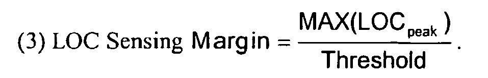
- If the LOC signal during a capture detection window following a subthreshold test pulse is larger in amplitude than expected, e.g. because of noise, false capture detections may be made. Therefore a safe margin between the maximum amplitude of the LOC signal and ER sensing threshold is desired to prevent false capture detections. An acceptable LOC sensing margin may be on the order of 0.1, for example.
- If the LOC sensing margin as calculated according to Equation (3) above is higher than a predetermined acceptable value, an alternative sensing vector may be tested at
step 364 or the reference sensing threshold may be adjusted. A less sensitive sensing threshold (higher numeric value) may be selected for the same test vector and the test may be repeated. - If the LOC sensing margin is acceptable, the time at which capture detection and/or the time of a detected peak amplitude of a capture signal may be evaluated at
decision step 354. If an early capture detection is made, for example within 10 ms of the end of the blanking interval, the detection may be due to a high polarization signal that has not substantially diminished such that it is interfering with evoked response sensing. An early capture detection may be suspected of being unreliable due to polarization artifact. - If a late capture detection is made, for example within 10 ms of the end of the capture detection window, an inverted slew of the sensed signal may have occurred due to over recharging of the pacing output capacitor after delivering the test pulse. Therefore, a late capture detection may be suspected of being unreliable due to capacitor over recharge.
- In addition or alternatively to examining the time of capture detection to exclude early or late capture detections, the time of one or more peak amplitude detections associated with a capture signal may be examined at
decision step 354. If the time of a peak amplitude detection is not consistent with prior peak amplitude detections, or is within the first or last few milliseconds of the capture detection window, the capture detection may be due to oversensing of noise resulting from electromagnetic interference, far-field cardiac signals, skeletal muscle motion, or otherwise. Therefore, the capture detection may be suspected of being unreliable due to noise. In alternative embodiments, the time and amplitude of detected peaks, and possibly other attributes, may be examined together to determine if these signal attributes are consistent. Inconsistencies may indicate a suboptimal sensing vector requiring a new pacing threshold search and vector optimization and re-determination of the associated signal attributes. - At
decision step 356, the number of peaks detected from a capture signal during a capture detection window may be examined. If a large number of peaks are detected, the signal may be contaminated with noise and the capture detection may be considered unreliable. Therefore, the number of peaks detected during a capture detection window may be compared to an acceptable value to eliminate noisy signals. A characteristic frequency of an evoked response signal sensed by a given sense amplifier may be used for determining an acceptable number of peaks, for example on the order of 1 to 4 peaks. If a greater number of peaks are detected during a capture detection window, the signal is noisy. For example, if 60 Hz noise is present, on the order of 6 to 10 peaks could be detected during a capture detection window. - If any of the decision steps 352 through 356 have a negative result, the pacing threshold result of the pacing threshold search may be concluded to be invalid at
step 362. An alternative sensing vector may be tested atstep 364 or the reference sensing threshold may be adjusted, for example in the case of a high LOC sensing margin. If all available sensing vectors have been exhausted, disabling automatic capture verification may be recommended. - Additional signal quality criteria may be defined and evaluated based on signal characteristics determined by
capture detection circuit 150 or digitized signal characteristics determined by A/D converter 222. Such signal characteristics may relate to the time or magnitude of peak amplitudes and time of detections as described above, or additionally or alternatively, relate to other signal characteristics such as signal slopes, integrals, threshold crossings, morphology or otherwise. Various signal quality criteria may therefore be defined based on ratios, differences, or other relationships between signal characteristics obtained from capture and/or LOC signals and a reference sensing threshold. -
Figure 11 is a flow chart summarizing a method for verifying evoked response signal quality during capture verification operations. Methods for determining signal quality parameters during a pacing threshold search may be adapted for use during capture verification operations to verify that signal quality remains acceptable. Verification of signal quality may be performed on a beat-by-beat basis during beat-by-beat capture verification or on a less frequent, sampled basis. If the signal quality is found to have deteriorated, a pacing threshold search and evoked response sensing vector optimization procedure, as described above, may be triggered. - At
step 402, a pacing pulse is delivered in accordance with thedevice 10 operating mode. Atstep 404, a capture detection window is set, and capture detectcircuit 150 detects signal peak amplitudes, and optionally peak times sensed using the most recently determined optimal evoked response sensing vector. If an evoked response is detected atstep 408, based on the previously determined optimal sensing threshold, the peak amplitude detected atstep 406 may be used to determine evoked response signal quality parameters atstep 410. - Signal quality parameters may be determined based on the peak amplitude information detected at
step 406 and loss of capture signal characteristics stored during the most recent pacing threshold search. For example, an ER SNR may be calculated as the ratio of the peak amplitude detected atstep 406 and the highest loss of capture peak amplitude stored during the last pacing threshold search. An evoked response sensing margin may be calculated as the peak amplitude detected atstep 406 and the current sensing threshold. Other signal characteristics used for evaluating signal quality during vector optimization methods, such as early or latent capture detections, number of peaks, etc., may also be used in determining signal quality parameters atstep 410. - If the signal quality parameters meet predetermined acceptable limits, as determined at
decision step 414, then beat-by-beat capture verification may continue, by returning to step 402, using the currently selected evoked response sensing vector and threshold. However, if the signal quality parameters are not acceptable, the evoked response signal sensed using the currently selected vector may have deteriorated. A pacing threshold search may be triggered atstep 416 allowing a sensing vector optimization procedure to be performed to reset the evoked response sensing vector and threshold, as necessary. - If an evoked response is not detected at
decision step 408, the loss of capture signal may optionally be examined for an acceptable loss of capture sensing margin atdecision step 412. The peak amplitude detected atstep 406 may be used to calculate a LOC sensing margin based on the currently selected sensing threshold and compared to an acceptable value atstep 412. If the LOC sensing margin, calculated as the ratio of the peak amplitude detected atstep 406 to the sensing threshold, is too high, a pacing threshold search and evoked response sensing vector optimization procedure may be triggered atstep 416. Worsening signal quality, due to increasing noise for example, may be identified by an increase in the LOC sensing margin before false capture detections are made due to a noisy signal. Thus, signal quality parameters may be used for ongoing verification of acceptable evoked response sensing during capture verification operations. - The circuitry and associated methods provided by the present invention thus allow an ER sensing vector to be optimized based on the quality of the capture (and loss of capture) signals. Rather than only indicating that a capture or LOC detection has been made, the ER sensing vector optimization methods included in the present invention for evaluating the capture and LOC signals provides information on the ER signal quality. Based on this information, unreliable ER sensing vectors and pacing threshold measurements may be eliminated. False capture or false LOC detections may be avoided. Hence, automatic capture verification and capture threshold searches may be performed more reliably when utilizing an optimized ER sensing vector and sensing threshold.
- The detailed descriptions of embodiments provided herein are therefore intended to illustrate the concepts of the present invention and are not to be considered limiting with regard to the following claims.
Claims (1)
- A system implemented in an implantable medical device, the system comprising:means (208) configured to select an evoked response sensing electrode pair;a pulse generator (80) configured to deliver a sequence of test pulses including a first set of test pulses having a first pulse energy exceeding a capture threshold and a second set of test pulses having a second pulse energy less than the capture threshold;a capture detection module (150) configured to receive a signal from the selected evoked response sensing electrode pair; anda processor (224) configured to receive a signal from the selected evoked response sensing electrode pair, configured to determine a maximum signal amplitude of the received signal following each of the test pulses included in the first set and the second set, configured to determine a minimum value of the determined maximum signal amplitudes corresponding to the first set of test pulses, configured to determine a signal quality parameter based on the minimum value, and configured to accept the selected evoked response sensing electrode pair in response to the signal quality parameter.
Applications Claiming Priority (3)
| Application Number | Priority Date | Filing Date | Title |
|---|---|---|---|
| US284870 | 1988-12-15 | ||
| US10/284,870 US7123963B2 (en) | 2002-10-31 | 2002-10-31 | Method of automatic evoked response sensing vector selection using evoked response waveform analysis |
| PCT/US2003/034885 WO2004039447A1 (en) | 2002-10-31 | 2003-10-31 | Method of automatic evoked response sensing vector selection using evoked response waveform analysis |
Publications (2)
| Publication Number | Publication Date |
|---|---|
| EP1578490A1 EP1578490A1 (en) | 2005-09-28 |
| EP1578490B1 true EP1578490B1 (en) | 2009-03-11 |
Family
ID=32175002
Family Applications (1)
| Application Number | Title | Priority Date | Filing Date |
|---|---|---|---|
| EP03778076A Expired - Lifetime EP1578490B1 (en) | 2002-10-31 | 2003-10-31 | System for automatic evoked response sensing vector selection using evoked response waveform analysis |
Country Status (7)
| Country | Link |
|---|---|
| US (1) | US7123963B2 (en) |
| EP (1) | EP1578490B1 (en) |
| JP (1) | JP4423201B2 (en) |
| AU (1) | AU2003286860A1 (en) |
| CA (1) | CA2501954A1 (en) |
| DE (1) | DE60326644D1 (en) |
| WO (1) | WO2004039447A1 (en) |
Families Citing this family (81)
| Publication number | Priority date | Publication date | Assignee | Title |
|---|---|---|---|---|
| US7177689B2 (en) | 2001-10-26 | 2007-02-13 | Cardiac Pacemakers, Inc. | Method and apparatus for capture verification and threshold determination |
| US7286876B2 (en) * | 2001-10-26 | 2007-10-23 | Cardiac Pacemakers, Inc. | Template-based capture verification for multi-site pacing |
| US7113823B2 (en) * | 2001-10-26 | 2006-09-26 | Cardiac Pacemakers, Inc. | Morphology-based optimization of cardiac resynchronization therapy |
| US20050091554A1 (en) * | 2003-08-07 | 2005-04-28 | Dmitrii Loukianov | Event time-stamping |
| US7412287B2 (en) * | 2003-12-22 | 2008-08-12 | Cardiac Pacemakers, Inc. | Automatic sensing vector selection for morphology-based capture verification |
| US7706866B2 (en) * | 2004-06-24 | 2010-04-27 | Cardiac Pacemakers, Inc. | Automatic orientation determination for ECG measurements using multiple electrodes |
| US8233983B2 (en) | 2004-12-17 | 2012-07-31 | St. Jude Medical Ab | Implantable heart stimulator and method for operation thereof |
| US7236828B2 (en) * | 2005-03-31 | 2007-06-26 | Medtronic, Inc. | Implantable cardioverter defibrillator with automatically adaptable sensing configuration |
| US7555340B2 (en) * | 2005-04-01 | 2009-06-30 | Cardiac Pacemakers, Inc. | Electrogram morphology-based CRT optimization |
| WO2007053064A1 (en) * | 2005-10-31 | 2007-05-10 | St. Jude Medical Ab | An implantable heart stimulating device, system and method |
| US7778696B2 (en) * | 2005-11-21 | 2010-08-17 | Cardiac Pacemakers, Inc. | Selection of cardiac capture verification modes |
| US20070179538A1 (en) * | 2006-01-30 | 2007-08-02 | Deno D C | Implantable subcutaneous medical device providing post-extra-systolic potentiation therapy |
| WO2007133130A1 (en) * | 2006-05-16 | 2007-11-22 | St. Jude Medical Ab | An implantable heart stimulating device and method |
| US8200341B2 (en) | 2007-02-07 | 2012-06-12 | Cameron Health, Inc. | Sensing vector selection in a cardiac stimulus device with postural assessment |
| US7623909B2 (en) * | 2006-05-26 | 2009-11-24 | Cameron Health, Inc. | Implantable medical devices and programmers adapted for sensing vector selection |
| US20070276452A1 (en) * | 2006-05-26 | 2007-11-29 | Cameron Health, Inc. | Implantable medical device systems having initialization functions and methods of operation |
| US8788023B2 (en) | 2006-05-26 | 2014-07-22 | Cameron Health, Inc. | Systems and methods for sensing vector selection in an implantable medical device |
| US7904153B2 (en) * | 2007-04-27 | 2011-03-08 | Medtronic, Inc. | Method and apparatus for subcutaneous ECG vector acceptability and selection |
| EP1995685A3 (en) * | 2007-05-21 | 2012-08-01 | Biotronik CRM Patent AG | Medical device for monitoring biological signal |
| US9037239B2 (en) | 2007-08-07 | 2015-05-19 | Cardiac Pacemakers, Inc. | Method and apparatus to perform electrode combination selection |
| US8265736B2 (en) | 2007-08-07 | 2012-09-11 | Cardiac Pacemakers, Inc. | Method and apparatus to perform electrode combination selection |
| US20090299421A1 (en) * | 2008-06-02 | 2009-12-03 | Medtronic, Inc. | Evaluation of implantable medical device sensing integrity based on evoked signals |
| WO2009148425A1 (en) * | 2008-06-02 | 2009-12-10 | Medtronic, Inc. | Impedance variability analysis to identify lead-related conditions |
| WO2009148428A1 (en) * | 2008-06-02 | 2009-12-10 | Medtronic, Inc. | Electrode lead integrity reports |
| US8126553B2 (en) * | 2008-06-02 | 2012-02-28 | Medtronic, Inc. | Sensing integrity determination based on cardiovascular pressure |
| WO2009148429A1 (en) | 2008-06-02 | 2009-12-10 | Medtronic, Inc. | Electrogram storage for suspected non-physiological episodes |
| US7974690B2 (en) * | 2008-06-30 | 2011-07-05 | Medtronic, Inc. | Lead integrity testing during suspected tachyarrhythmias |
| US9522277B2 (en) * | 2008-07-28 | 2016-12-20 | Medtronic, Inc. | Lead integrity testing triggered by sensed signal saturation |
| US7953488B2 (en) * | 2008-07-31 | 2011-05-31 | Medtronic, Inc. | Pre-qualification of an alternate sensing configuration |
| JP5591239B2 (en) * | 2008-08-28 | 2014-09-17 | コーニンクレッカ フィリップス エヌ ヴェ | Nutrition tube |
| US8078277B2 (en) | 2008-10-29 | 2011-12-13 | Medtronic, Inc. | Identification and remediation of oversensed cardiac events using far-field electrograms |
| US10118042B2 (en) | 2008-10-31 | 2018-11-06 | Medtronic, Inc. | Lead integrity testing triggered by sensed asystole |
| US9931049B2 (en) * | 2009-11-13 | 2018-04-03 | The General Hospital Corporation | Method and apparatus for the detection and control of repolarization alternans |
| US8396543B2 (en) * | 2010-01-28 | 2013-03-12 | Medtronic, Inc. | Storage of data for evaluation of lead integrity |
| US20110208261A1 (en) * | 2010-02-24 | 2011-08-25 | Pacesetter, Inc. | Systems and methods for assessing and reprogramming sensing vectors for use with an implantable cardiac rhythm management device |
| US9138585B2 (en) | 2010-08-06 | 2015-09-22 | Cardiac Pacemakers, Inc. | User interface system for use with multipolar pacing leads |
| US8401646B2 (en) | 2010-10-21 | 2013-03-19 | Medtronic, Inc. | Method and apparatus to determine the relative energy expenditure for a plurality of pacing vectors |
| US9020596B2 (en) | 2011-07-15 | 2015-04-28 | Cardiac Pacemakers, Inc. | Management of fusion beat detection during capture threshold determination |
| US8626291B2 (en) | 2011-07-28 | 2014-01-07 | Medtronic, Inc. | Method for discriminating anodal and cathodal capture |
| US8527050B2 (en) | 2011-07-28 | 2013-09-03 | Medtronic, Inc. | Method for discriminating anodal and cathodal capture |
| US9554717B2 (en) | 2011-07-29 | 2017-01-31 | Pacesetter, Inc. | Devices, systems and methods to monitor and treat heart failure (HF) |
| US8798731B2 (en) | 2011-07-29 | 2014-08-05 | Pacesetter, Inc. | Devices, systems and methods to perform arrhythmia discrimination based on the atrial and ventricular activation times |
| US9002453B2 (en) | 2011-07-29 | 2015-04-07 | Pacesetter, Inc. | Devices, systems and methods to perform arrhythmia discrimination based on R-R interval stability corresponding to a plurality of ventricular regions |
| US8774909B2 (en) | 2011-09-26 | 2014-07-08 | Medtronic, Inc. | Episode classifier algorithm |
| US8437840B2 (en) | 2011-09-26 | 2013-05-07 | Medtronic, Inc. | Episode classifier algorithm |
| US8744560B2 (en) | 2011-09-30 | 2014-06-03 | Medtronic, Inc. | Electrogram summary |
| US9668668B2 (en) | 2011-09-30 | 2017-06-06 | Medtronic, Inc. | Electrogram summary |
| US8521281B2 (en) | 2011-10-14 | 2013-08-27 | Medtronic, Inc. | Electrogram classification algorithm |
| US8886296B2 (en) | 2011-10-14 | 2014-11-11 | Medtronic, Inc. | T-wave oversensing |
| US9199087B2 (en) | 2011-11-21 | 2015-12-01 | Medtronic, Inc. | Apparatus and method for selecting a preferred pacing vector in a cardiac resynchronization device |
| US9037238B2 (en) | 2011-11-21 | 2015-05-19 | Michael C. Soldner | Method for efficient delivery of dual site pacing |
| US8682433B2 (en) | 2011-11-21 | 2014-03-25 | Medtronic, Inc. | Method for efficient delivery of dual site pacing |
| US8750998B1 (en) * | 2012-12-06 | 2014-06-10 | Medtronic, Inc. | Effective capture test |
| US9061157B2 (en) | 2012-12-06 | 2015-06-23 | Medtronic, Inc. | Effective capture |
| US8750999B1 (en) * | 2012-12-06 | 2014-06-10 | Medtronic, Inc. | Effective capture test |
| US8738132B1 (en) * | 2012-12-06 | 2014-05-27 | Medtronic, Inc. | Effective capture test |
| US9320905B2 (en) | 2012-12-06 | 2016-04-26 | Medtronic, Inc. | Effective capture test |
| US8666490B1 (en) | 2012-12-13 | 2014-03-04 | Pacesetter, Inc. | Capture confirmation for multi-site pacing |
| US9579065B2 (en) | 2013-03-12 | 2017-02-28 | Cameron Health Inc. | Cardiac signal vector selection with monophasic and biphasic shape consideration |
| US10434318B2 (en) | 2013-12-18 | 2019-10-08 | Cardiac Pacemakers, Inc. | Systems and methods for facilitating selecting of one or more vectors in a medical device |
| US9457191B2 (en) | 2013-12-18 | 2016-10-04 | Cardiac Pacemakers, Inc. | System and method for assessing and selecting stimulation vectors in an implantable cardiac resynchronization therapy device |
| US9750942B2 (en) | 2013-12-18 | 2017-09-05 | Cardiac Pacemakers, Inc. | Systems and methods for determining parameters for each of a plurality of vectors |
| US9339656B2 (en) | 2014-02-28 | 2016-05-17 | Medtronic, Inc. | Methods and systems for identifying reasons for ineffective left ventricular capture in cardiac resynchronization therapy based on EGM morphology |
| US10376705B2 (en) | 2014-04-01 | 2019-08-13 | Medtronic, Inc. | Method and apparatus for discriminating tachycardia events in a medical device |
| US9526908B2 (en) | 2014-04-01 | 2016-12-27 | Medtronic, Inc. | Method and apparatus for discriminating tachycardia events in a medical device |
| US9808640B2 (en) | 2014-04-10 | 2017-11-07 | Medtronic, Inc. | Method and apparatus for discriminating tachycardia events in a medical device using two sensing vectors |
| US9352165B2 (en) | 2014-04-17 | 2016-05-31 | Medtronic, Inc. | Method and apparatus for verifying discriminating of tachycardia events in a medical device having dual sensing vectors |
| US9795312B2 (en) * | 2014-04-24 | 2017-10-24 | Medtronic, Inc. | Method and apparatus for adjusting a blanking period for selecting a sensing vector configuration in a medical device |
| US10252067B2 (en) | 2014-04-24 | 2019-04-09 | Medtronic, Inc. | Method and apparatus for adjusting a blanking period during transitioning between operating states in a medical device |
| US10278601B2 (en) | 2014-04-24 | 2019-05-07 | Medtronic, Inc. | Method and apparatus for selecting a sensing vector configuration in a medical device |
| US10244957B2 (en) | 2014-04-24 | 2019-04-02 | Medtronic, Inc. | Method and apparatus for selecting a sensing vector configuration in a medical device |
| WO2015164293A1 (en) * | 2014-04-24 | 2015-10-29 | Medtronic, Inc. | Method and apparatus for selecting a sensing vector configuration in a medical device |
| US9610025B2 (en) | 2014-07-01 | 2017-04-04 | Medtronic, Inc. | Method and apparatus for verifying discriminating of tachycardia events in a medical device having dual sensing vectors |
| WO2016044944A1 (en) * | 2014-09-24 | 2016-03-31 | Vivosonic Inc. | System, method and apparatus for detection of signals in noise and monitoring state of consciousness |
| US9549681B2 (en) | 2014-11-18 | 2017-01-24 | Siemens Medical Solutions Usa, Inc. | Matrix-based patient signal analysis |
| US9741342B2 (en) * | 2014-11-26 | 2017-08-22 | Panasonic Intellectual Property Corporation Of America | Method and apparatus for recognizing speech by lip reading |
| US9750943B2 (en) | 2015-02-26 | 2017-09-05 | Medtronic, Inc. | Monitoring of pacing capture using acceleration |
| US11801390B2 (en) | 2018-06-06 | 2023-10-31 | Medtronic, Inc. | Identification and adjustment for loss of effective cardiac resynchronization therapy |
| US12527958B2 (en) | 2022-06-30 | 2026-01-20 | Medtronic, Inc. | Dynamically optimized evoked response sensing |
| EP4727637A1 (en) * | 2023-06-13 | 2026-04-22 | Medtronic, Inc. | Noise identification and reduction for recording of signals with cardiac activity on spinal cord stimulation (scs) leads |
| US20250303161A1 (en) * | 2024-03-29 | 2025-10-02 | Advanced Bionics Llc | Electrode electrical status-based designation of electrodes of an implantable stimulator for measuring an evoked response |
Citations (1)
| Publication number | Priority date | Publication date | Assignee | Title |
|---|---|---|---|---|
| US5855594A (en) * | 1997-08-08 | 1999-01-05 | Cardiac Pacemakers, Inc. | Self-calibration system for capture verification in pacing devices |
Family Cites Families (26)
| Publication number | Priority date | Publication date | Assignee | Title |
|---|---|---|---|---|
| US4502492A (en) * | 1983-04-28 | 1985-03-05 | Medtronic, Inc. | Low-polarization low-threshold electrode |
| US4549548A (en) * | 1983-09-14 | 1985-10-29 | Vitafin N.V. | Pacemaker system with automatic event-programmed switching between unipolar and bipolar operation |
| US4628934A (en) * | 1984-08-07 | 1986-12-16 | Cordis Corporation | Method and means of electrode selection for pacemaker with multielectrode leads |
| US5222493A (en) * | 1990-10-01 | 1993-06-29 | Siemens Pacesetter, Inc. | Verification of capture using an indifferent electrode mounted on the pacemaker connector top |
| US5117824A (en) * | 1990-11-14 | 1992-06-02 | Medtronic, Inc. | Apparatus for monitoring electrical physiologic signals |
| EP0578748B1 (en) * | 1991-04-05 | 1996-05-01 | Medtronic, Inc. | Subcutaneous multi-electrode sensing system |
| US5324310A (en) * | 1992-07-01 | 1994-06-28 | Medtronic, Inc. | Cardiac pacemaker with auto-capture function |
| US5350410A (en) * | 1992-11-23 | 1994-09-27 | Siemens Pacesetter, Inc. | Autocapture system for implantable pulse generator |
| US5683431A (en) * | 1996-03-27 | 1997-11-04 | Medtronic, Inc. | Verification of capture by sensing evoked response across cardioversion electrodes |
| SE9602846D0 (en) * | 1996-07-23 | 1996-07-23 | Pacesetter Ab | A stimulation device |
| US5707398A (en) * | 1996-11-12 | 1998-01-13 | Pacesetter, Inc. | Automatic determination of optimum electrode configuration for a cardiac stimulator |
| US5873898A (en) * | 1997-04-29 | 1999-02-23 | Medtronic, Inc. | Microprocessor capture detection circuit and method |
| US5861013A (en) * | 1997-04-29 | 1999-01-19 | Medtronic Inc. | Peak tracking capture detection circuit and method |
| US6434428B1 (en) * | 1998-07-29 | 2002-08-13 | Pacesetter, Inc. | System and method for optimizing far-field R-wave sensing by switching electrode polarity during atrial capture verification |
| US6505071B1 (en) | 1999-12-15 | 2003-01-07 | Cardiac Pacemakers, Inc. | Cardiac management device with capability of noise detection in automatic capture verification |
| US20010049543A1 (en) * | 2000-05-15 | 2001-12-06 | Kroll Mark W. | Method and apparatus for biventricular stimulation and capture monitoring |
| US6782291B1 (en) * | 2000-09-05 | 2004-08-24 | Pacesetter, Inc. | Implantable cardiac stimulation device with automatic evoked response sensing electrode configuration selection and method |
| US6430448B1 (en) * | 2000-11-07 | 2002-08-06 | Pacesetter, Inc. | Stimulating electrode having low polarization and method of making same |
| US6567701B2 (en) * | 2000-12-21 | 2003-05-20 | Medtronic, Inc. | Method and system for discriminating captured beats from non-captured beats in a cardiac pacing system |
| US6643546B2 (en) * | 2001-02-13 | 2003-11-04 | Quetzal Biomedical, Inc. | Multi-electrode apparatus and method for treatment of congestive heart failure |
| US6613826B2 (en) * | 2001-09-01 | 2003-09-02 | Toyota Technical Center, U.S.A., Inc. | Aqueous coating composition |
| US7006869B2 (en) * | 2001-09-10 | 2006-02-28 | Pacesetter, Inc. | Method and device for enhanced capture tracking by discrimination of fusion beats |
| US7177689B2 (en) * | 2001-10-26 | 2007-02-13 | Cardiac Pacemakers, Inc. | Method and apparatus for capture verification and threshold determination |
| US6937901B2 (en) * | 2001-10-31 | 2005-08-30 | Cardiac Pacemakers, Inc. | Capture verification for cardiac resynchronization pacing optimization |
| US6915164B2 (en) * | 2002-04-16 | 2005-07-05 | Pacesetter, Inc. | Automatic capture using independent channels in bi-chamber stimulation |
| US6978178B2 (en) | 2002-04-30 | 2005-12-20 | Medtronic, Inc. | Method and apparatus for selecting an optimal electrode configuration of a medical electrical lead having a multiple electrode array |
-
2002
- 2002-10-31 US US10/284,870 patent/US7123963B2/en not_active Expired - Fee Related
-
2003
- 2003-10-31 EP EP03778076A patent/EP1578490B1/en not_active Expired - Lifetime
- 2003-10-31 WO PCT/US2003/034885 patent/WO2004039447A1/en not_active Ceased
- 2003-10-31 AU AU2003286860A patent/AU2003286860A1/en not_active Abandoned
- 2003-10-31 CA CA002501954A patent/CA2501954A1/en not_active Abandoned
- 2003-10-31 JP JP2004548650A patent/JP4423201B2/en not_active Expired - Fee Related
- 2003-10-31 DE DE60326644T patent/DE60326644D1/en not_active Expired - Lifetime
Patent Citations (1)
| Publication number | Priority date | Publication date | Assignee | Title |
|---|---|---|---|---|
| US5855594A (en) * | 1997-08-08 | 1999-01-05 | Cardiac Pacemakers, Inc. | Self-calibration system for capture verification in pacing devices |
Also Published As
| Publication number | Publication date |
|---|---|
| US7123963B2 (en) | 2006-10-17 |
| JP2006504474A (en) | 2006-02-09 |
| WO2004039447A1 (en) | 2004-05-13 |
| EP1578490A1 (en) | 2005-09-28 |
| US20040088018A1 (en) | 2004-05-06 |
| JP4423201B2 (en) | 2010-03-03 |
| AU2003286860A1 (en) | 2004-05-25 |
| CA2501954A1 (en) | 2004-05-13 |
| DE60326644D1 (en) | 2009-04-23 |
Similar Documents
| Publication | Publication Date | Title |
|---|---|---|
| EP1578490B1 (en) | System for automatic evoked response sensing vector selection using evoked response waveform analysis | |
| US6731985B2 (en) | Implantable cardiac stimulation system and method for automatic capture verification calibration | |
| US6567701B2 (en) | Method and system for discriminating captured beats from non-captured beats in a cardiac pacing system | |
| US6477422B1 (en) | Method and apparatus for capture detection | |
| US7076290B2 (en) | Method and apparatus for detecting and discriminating arrhythmias | |
| US8792971B2 (en) | Method and apparatus for identifying oversensing using far-field intracardiac electrograms and marker channels | |
| US20050038478A1 (en) | Activation recovery interval for classification of cardiac beats in an implanted device | |
| US6865421B2 (en) | Method and apparatus for automatic capture verification using polarity discrimination of evoked response | |
| US7706865B1 (en) | Apparatus and method for cardiac rhythm detection | |
| US20030144595A1 (en) | Implantable syncope monitor and method of using the same | |
| US20080269624A1 (en) | Morphology based arrhythmia detection | |
| US6195584B1 (en) | Method and apparatus for determining atrial lead dislocation | |
| US20040127949A1 (en) | Method and system for detecting capture with cancellation of pacing artifact | |
| EP2654888B1 (en) | Rate initialization and overdrive pacing for capture threshold testing | |
| US11766207B2 (en) | Methods, devices and systems for improving R-wave detection and arrhtymia detection accuracy | |
| US8082036B2 (en) | Automatic signal amplitude measurement system in the setting of abnormal rhythms | |
| EP1899008B1 (en) | Apparatus for validating a pacing train associated with t-shock delivery | |
| US6766197B1 (en) | System and method with improved automatic testing functions for automatic capture verification | |
| US6947794B1 (en) | System and method with improved automatic testing functions for defining capture thresholds | |
| US20060241710A1 (en) | System and method for capture management | |
| US11806536B2 (en) | Method and device for managing his bundle pacing in a non-tracking mode during AF/AT | |
| US20090281588A1 (en) | Determining atrial time periods in conjunction with real-time testing |
Legal Events
| Date | Code | Title | Description |
|---|---|---|---|
| PUAI | Public reference made under article 153(3) epc to a published international application that has entered the european phase |
Free format text: ORIGINAL CODE: 0009012 |
|
| 17P | Request for examination filed |
Effective date: 20050531 |
|
| AK | Designated contracting states |
Kind code of ref document: A1 Designated state(s): AT BE BG CH CY CZ DE DK EE ES FI FR GB GR HU IE IT LI LU MC NL PT RO SE SI SK TR |
|
| AX | Request for extension of the european patent |
Extension state: AL LT LV MK |
|
| DAX | Request for extension of the european patent (deleted) | ||
| RBV | Designated contracting states (corrected) |
Designated state(s): CH DE FR LI NL SE |
|
| RIN1 | Information on inventor provided before grant (corrected) |
Inventor name: SAWCHUK, ROBERT, T. Inventor name: HEINKS, MICHAEL, W. Inventor name: GRADEN, DAVID, W. |
|
| 17Q | First examination report despatched |
Effective date: 20080325 |
|
| GRAP | Despatch of communication of intention to grant a patent |
Free format text: ORIGINAL CODE: EPIDOSNIGR1 |
|
| RTI1 | Title (correction) |
Free format text: SYSTEM FOR AUTOMATIC EVOKED RESPONSE SENSING VECTOR SELECTION USING EVOKED RESPONSE WAVEFORM ANALYSIS |
|
| GRAS | Grant fee paid |
Free format text: ORIGINAL CODE: EPIDOSNIGR3 |
|
| GRAA | (expected) grant |
Free format text: ORIGINAL CODE: 0009210 |
|
| AK | Designated contracting states |
Kind code of ref document: B1 Designated state(s): CH DE FR LI NL SE |
|
| REG | Reference to a national code |
Ref country code: CH Ref legal event code: EP |
|
| REF | Corresponds to: |
Ref document number: 60326644 Country of ref document: DE Date of ref document: 20090423 Kind code of ref document: P |
|
| PG25 | Lapsed in a contracting state [announced via postgrant information from national office to epo] |
Ref country code: NL Free format text: LAPSE BECAUSE OF FAILURE TO SUBMIT A TRANSLATION OF THE DESCRIPTION OR TO PAY THE FEE WITHIN THE PRESCRIBED TIME-LIMIT Effective date: 20090311 |
|
| NLV1 | Nl: lapsed or annulled due to failure to fulfill the requirements of art. 29p and 29m of the patents act | ||
| PG25 | Lapsed in a contracting state [announced via postgrant information from national office to epo] |
Ref country code: SE Free format text: LAPSE BECAUSE OF FAILURE TO SUBMIT A TRANSLATION OF THE DESCRIPTION OR TO PAY THE FEE WITHIN THE PRESCRIBED TIME-LIMIT Effective date: 20090611 |
|
| PLBE | No opposition filed within time limit |
Free format text: ORIGINAL CODE: 0009261 |
|
| STAA | Information on the status of an ep patent application or granted ep patent |
Free format text: STATUS: NO OPPOSITION FILED WITHIN TIME LIMIT |
|
| 26N | No opposition filed |
Effective date: 20091214 |
|
| REG | Reference to a national code |
Ref country code: CH Ref legal event code: PL |
|
| PG25 | Lapsed in a contracting state [announced via postgrant information from national office to epo] |
Ref country code: CH Free format text: LAPSE BECAUSE OF NON-PAYMENT OF DUE FEES Effective date: 20091031 Ref country code: LI Free format text: LAPSE BECAUSE OF NON-PAYMENT OF DUE FEES Effective date: 20091031 |
|
| REG | Reference to a national code |
Ref country code: FR Ref legal event code: PLFP Year of fee payment: 13 |
|
| REG | Reference to a national code |
Ref country code: FR Ref legal event code: PLFP Year of fee payment: 14 |
|
| PGFP | Annual fee paid to national office [announced via postgrant information from national office to epo] |
Ref country code: FR Payment date: 20161025 Year of fee payment: 14 Ref country code: DE Payment date: 20161027 Year of fee payment: 14 |
|
| REG | Reference to a national code |
Ref country code: DE Ref legal event code: R119 Ref document number: 60326644 Country of ref document: DE |
|
| REG | Reference to a national code |
Ref country code: FR Ref legal event code: ST Effective date: 20180629 |
|
| PG25 | Lapsed in a contracting state [announced via postgrant information from national office to epo] |
Ref country code: DE Free format text: LAPSE BECAUSE OF NON-PAYMENT OF DUE FEES Effective date: 20180501 |
|
| PG25 | Lapsed in a contracting state [announced via postgrant information from national office to epo] |
Ref country code: FR Free format text: LAPSE BECAUSE OF NON-PAYMENT OF DUE FEES Effective date: 20171031 |