EP1578216B1 - Juice extractor with enhanced quality and yield performance and methods of making same - Google Patents
Juice extractor with enhanced quality and yield performance and methods of making same Download PDFInfo
- Publication number
- EP1578216B1 EP1578216B1 EP03808959A EP03808959A EP1578216B1 EP 1578216 B1 EP1578216 B1 EP 1578216B1 EP 03808959 A EP03808959 A EP 03808959A EP 03808959 A EP03808959 A EP 03808959A EP 1578216 B1 EP1578216 B1 EP 1578216B1
- Authority
- EP
- European Patent Office
- Prior art keywords
- cutter
- base
- cutting blade
- cup
- juice extractor
- Prior art date
- Legal status (The legal status is an assumption and is not a legal conclusion. Google has not performed a legal analysis and makes no representation as to the accuracy of the status listed.)
- Expired - Lifetime
Links
Images


Classifications
-
- A—HUMAN NECESSITIES
- A23—FOODS OR FOODSTUFFS; TREATMENT THEREOF, NOT COVERED BY OTHER CLASSES
- A23N—MACHINES OR APPARATUS FOR TREATING HARVESTED FRUIT, VEGETABLES OR FLOWER BULBS IN BULK, NOT OTHERWISE PROVIDED FOR; PEELING VEGETABLES OR FRUIT IN BULK; APPARATUS FOR PREPARING ANIMAL FEEDING- STUFFS
- A23N1/00—Machines or apparatus for extracting juice
- A23N1/003—Machines or apparatus for extracting juice especially for citrus fruits
Definitions
- This invention relates to the field of food processing, and, more particularly to juice extractors.
- Citrus juice extraction on a commercial scale can be advantageously performed with a juice extractor including upper and lower cups that move relative to one another along a reciprocal path of travel.
- the sides of both the upper and lower cups typically comprise fingers that support a fruit so that it can be squeezed without bursting.
- the fingers of the upper cup interdigitate or intermesh with those of the lower cup.
- An orange or other fruit can be fed, for example, to the bottom cup by a cam-operated feeding device.
- the upper and lower cups are then brought together so that the respective fingers of the cup intermesh and the fruit therebetween is accordingly squeezed.
- Sharp, typically circular, cutters are positioned in the top and bottom cups. As the cups move relative to one another, the fruit is pressed against the cutters. The cutters cut plugs from both the top and bottom portions of the fruit as the interdigitating fingers of the two cups mesh together.
- the cutting of the plug from the top portion of the fruit promotes separation of the peel from the internal portions of the fruit (i.e., juice and pulp).
- the plug cut from the lower portion of the fruit allows the internal portions of the fruit to be forced down into a strainer tube positioned just below the lower cup cutter.
- the strainer tube is positioned within a manifold.
- an orifice tube moves upward into the strainer tube applying pressure to the internal portion of the fruit therein. This causes the juice and juice sacs, due to their small particle size, to flow through small holes of the strainer tube and into the juice manifold, thus separating out the juice and pulp.
- Core material that typically includes membrane, seeds, and peel plugs is discharged out of the bottom of the orifice tube.
- Such extractors are disclosed, for example, in U. S. Pat. Nos. 5,970, 861 and 5,992, 311 to Suter et al.
- the juice extractor should accomplish juice extraction rapidly with a high yield rate (i.e., the quantity of juice recovered relative to the amount of fruit processed). Quality considerations, though, dictate that care should be taken regarding the peel oil extracted from the peel during cutting and squeezing. Such oil, if mixed into the juice in higher quantities, reduces the quality of the juice.
- U. S. Pat. No. 5,070, 778 to Cross et al. discloses a cutting head comprising a core and a cylindrical blade portion surrounding the core in a spaced relation thereto. Side openings or windows are formed in the side surface of the cylindrical blade portion, and the core has a conical shape adjacent the windows. Accordingly, pressure from the orifice tube pushes some peel oil out the sides of the cutting head through the windows. Rings of fruit peel resulting from cutting plugs in the fruit nonetheless may be mixed in with the internal portions of the fruit. If so, the result is an increase in peel oil in the juice ultimately produced, and, accordingly, a reduction in the quality of the juice.
- the upper cutter is sized slightly larger than the lower cutter.
- the peel clearance that is, the space between the outer diameter of the upper cutter and adjacent upper cup portions, is typically the same for either one inch or three-quarter inch components, and is based upon the fruit.
- a 22.2 mm (seven-eighths inch) lower cutter was made and used along with a standard sized upper cup for 25.4 mm (one inch) extractor components. Accordingly, to provide the proper peel clearance, the wall thickness of the upper cutter was enlarged to about 2.39 mm (0.094 inches). The thick-walled upper cutter also required a larger bore on the lower cup to provide adequate clearance. Unfortunately, even this attempted arrangement of components was not fully satisfactory in meeting juice quality and yield goals.
- a cutter for use with a juice extractor of the kind including first and second cups that are movable for compressing fruit therebetween during juice extraction, the cutter comprising a cutter base and a cutting blade extending therefrom, characterised in that the cutter base has at least one base opening therein, and the cutting blade extends outwardly from the cutter base to define an interior passageway in communication with the at least one base opening through which debris (e.g., fruit peel and peel oil) can be released.
- the invention also extends to juice extractors comprising first and second cups and a cutter as defined in claims 11 and 17.
- the juice extractor may comprise first and second cups that move relatively to one another for compressing a fruit therebetween during juice extraction.
- the first and second cups may move relatively to one another along a substantially linear reciprocal path of travel in some embodiments.
- the first cup may comprise a plurality of fingers extending radially outwardly to define a first cup bore, which, in turn, may receive the first cutter.
- the first cutter may include a first cutter base having at least one base opening that may open outwardly to a periphery defined by adjacent base portions.
- a first cutting blade may extend outwardly from the first cutter base to define an interior passageway.
- the interior passageway may be in communication with the at least one base opening to release debris therethrough.
- the first cutter may further comprise a shaft extending outwardly from the first cutter base opposite the first cutting blade, and the first cutting blade may have a cylindrical shape and a beveled cutting edge.
- the first cutter may also include a core extending outwardly from the first cutter base in a spaced relation from the first cutting blade.
- the first cutting blade may have at least one blade opening, and the at least one blade opening may be in communication with the at least one base opening.
- the juice extractor may also include at least one debris deflector adjacent the first cutter base.
- the at least one debris deflector may have a pointed edge directed along the interior passageway.
- at least one L-shaped connector With the first cutting blade having at least one blade opening in communication with the at least one base opening, at least one L-shaped connector may be defined.
- the at least one L-shaped connector may connect the first cutter base and first cutting blade together, and the at least one debris deflector may be adjacent an inner portion of the at least one L-shaped support leg.
- the second cup may comprise a ring base defining a second cup bore, and a second plurality of fingers extending outwardly from the ring base.
- the second cup may further comprise a second cutter that includes a second cutting blade that is sized to be received within the interior passageway of the first cutter.
- a flange may extend outwardly from the second cutting blade to mount the second cutter in the second cup bore.
- the flange may be at a level flush with or above adjacent portions of the ring base.
- the flange may serve to direct fruit peel cut by the first and second cutters away from the internal portions of fruit obtained by squeezing the fruit between the first and second cups. By preventing the fruit peel from mixing in with the internal portions, the flange reduces the amount of peel oil in the juice that is ultimately produced. The flange thus enhances juice quality without reducing juice yield.
- An additional aspect relates to a method of making a cutter for use with a juice extractor comprising first and second cups that move relative to one another to compress fruit therebetween during juice extraction.
- the method may include providing a cutter base having at least one base opening therein.
- the method also may include connecting a cutting blade extending outwardly from the cutter base to define an interior passageway that is in communication with the at least one base opening so that debris may be released therethrough.
- the juice extractor 20 illustratively includes first and second cups 22, 24 between which a fruit 21 (e.g., orange, grapefruit, etc.) may be held. With the fruit therebetween, the first and second cups 22, 24 come together by moving relative to one another illustratively along a substantially linear reciprocal path of travel, for example. The fruit peel is separated and the internal portions of the fruit are extracted as the first and second cups 22, 24 come together thereby compressing the fruit 21 as will be readily understood by those skilled in the art.
- a fruit 21 e.g., orange, grapefruit, etc.
- the fruit is held in the second cup 24 with the first cup 22 illustratively descending downwardly from above the second cup 24 and onto the fruit 21.
- a cam drive mechanism 31 connected to the first cup 22 by a drive linkage 29 drives the first cup linearly downward.
- the first and second cups 22, 24 may be oriented in the same horizontal plane, and each may move toward the other in a horizontal direction driven by one of various drive mechanisms known to those skilled in the art.
- first cup 22 comprises a first plurality of fingers 23, and the second cup 24 comprises a second plurality of fingers 25. Both pluralities of fingers 23, 25 extend outwardly to intermesh and compress the fruit 21 as the respective cups 22, 24 move together.
- the first plurality of fingers 23 extends radially outwardly to define a first cup bore 26.
- a first cutter 28 is received within the first cup bore 26 such that it is positioned within a top portion of the first cup 22.
- the first cutter 28 cuts a plug in a top portion of the fruit 21 to permit a separation of the fruit peel from interior portions of the fruit. As will be readily understood by those skilled in the art, this helps prevent the fruit 21 from bursting as it is squeezed between the respective pluralities of fingers 23, 25 of the first and second cups 22,24.
- the first cutter 28 illustratively comprises a first cutter base 30 having three base openings 32A, 32B, 32C. As will be readily appreciated by those skilled in the art, the first cutter 28 may alternately have more than three base openings or it may have as few as one.
- the first cutter 28 further has a first cutting blade 34 extending outwardly from the first cutter base 30.
- the first cutting blade 34 has a cylindrical shape and a beveled cutting edge.
- the first cutting blade 34 in extending outwardly from the first cutter base 30, defines an interior passageway 36.
- the interior passageway 36 is in communication with the base openings 32A, 32B, 32C and thus permits the release of debris therethrough.
- the interior passageway 36 through which debris such as fruit peel is released, lends the first cutter 28 distinct advantages over conventional cutters having no or only side openings.
- the first cutter 28 of the present invention cuts into the fruit 21, the fruit peel and other debris is much less likely to become trapped or wedged therein.
- the debris is pushed along and out the interior passageway 36. Specifically, if the first cup 22 is oriented above the second cup 24 and descends onto the fruit 21, the resulting pressure forces the debris upwardly and out from the first cutter 28 (as indicated by the arrows 27 in FIG. 2 ).
- each of the base openings 32A, 32B, 32C of the first cutter 28 opens outwardly to a periphery defined by adjacent base portions 40A, 40B, 40C. This accordingly enhances the release of debris through the interior passageway 36.
- the first cutting blade 34 has three blade openings 42A, 42B, 42C therein.
- each blade opening 42A, 42B, 42C is illustratively in communication with a respective one of the three base openings 32A, 32B, 32C thus further enhancing the release of debris through the interior passageway 36.
- the first cutter 28 may include a core 38 that extends outwardly from the first cutter base 30 so that the core is positioned within the first cutting blade 34.
- the optionally included core 38 within the first cutting blade 32 is in a spaced relation from the first cutting blade.
- first cutter 28 may optionally include debris deflectors 44 adjacent the first cutter base 30. As illustrated, each debris deflector 44 has a pointed edge 46 directed toward the interior passageway 36. A blade opening 42A in communication with a base opening 32A defines an L- shaped support leg that connects together the first cutter base 30 and the first cutting blade 34. The debris deflector 44 is illustratively adjacent an inner portion of an L-shaped support leg as shown.
- the second cup 24 illustratively comprises a ring base 50 defining a second cup bore 52.
- the second plurality of fingers 25 extends outwardly from the ring base 50.
- the second cup 24 further mounts a second cutter 54 within the second cup bore 52.
- the second cutter 54 illustratively includes a second cutting blade 56.
- the second cutting blade 56 is sized so that it can be received within the interior passageway 36 of the first cutter 28.
- a flange 58 extends outwardly from the second cutting blade 56 to mount the second cutter 54 in the second cup bore 52.
- the flange 58 is illustratively at a level flush with adjacent portions of the ring base 50. As will be readily understood by those skilled in the art the flange 58 may also be at a level above the ring base 50.
- the flange 58 serves to prevent cut and separated fruit peel, including the peel ring resulting from the cutting of plugs in the fruit 21, from becoming mixed in with the internal portions squeezed from the fruit by the first and second cups 22, 24. Accordingly, without reducing juice yield, the flange 58 enhances juice quality by lessening the amount of peel oil that would otherwise be added to the juice during squeezing.
- the optionally included debris deflectors 44 may cooperate with the flange 58 by further segmenting the fruit peel and deflecting it away from the first and second cutters 22, 24 and, hence, away from the internal portions of the fruit 21. Again, the deflection of the peel ring away from the internal portions squeezed from the fruit 21 reduces the amount of peel oil in the juice ultimately produced, thereby enhancing juice quality without reducing juice yield.
- a shaft 60 illustratively extends outwardly from the first cutter base 30 opposite the first cutting blade 34.
- the shaft 60 may secure the first cutter 28 to the drive linkage 29 connected to the cam drive mechanism 31 that illustratively drives the first cup 22 down onto the fruit 21 during juice extraction.
- the fruit 21 is squeezed as the cam drive mechanism 31 drives the first cup 22 together with the second cup 24.
- the first cutter 28 cuts a top plug in the fruit as the first cup 22 moves against the fruit 21.
- the fruit 21 is also forced against the second cutting blade 56, which cuts a bottom plug into a bottom portion of the fruit 21.
- the internal portions 62 of the fruit 21 are forced through the bottom portion plug and into a prefinisher tube 64. Separated fruit peel is discharged between the first cup 22 and the first cutter 28. As detailed above, any fruit peel or debris within the first cutter 28 is released through the interior passageway 36.
- An additional aspect relates to a method of making a cutter 28 for use with a juice extractor 20 that includes first and second cups 22, 24 that move relatively with one another to compress fruit therebetween during juice extraction.
- the method illustrated by flow chart 70 of FIG. 8 includes, after starting (Block 72), providing a cutter base 30 that has at least one base opening 32A, 32B, 32C therein (Block 74).
- Providing a cutter base 30 having at least one base opening 32A, 32B, 32C may entail providing at least one base opening that opens outwardly to a periphery defined by adjacent base portions 40A, 40B, 40C.
- the method further illustratively includes, at Block 76, connecting a cutting blade 34 to extend outwardly from the cutter base 28 to thereby define an interior passageway 36 in communication with the at least one base opening 32A, 32B, 32C so that debris may be released therethrough.
- the method optionally may further entail providing the cutting blade 34 with at least one blade opening 42A, 42B, 42C therein so that the at least one blade opening is in communication with at least one base opening 32A, 32B, 32C.
- the method further includes at Block 78, optionally connecting a core 38 to extend outwardly from the cutter base 28 so that it is positioned within the cutting blade in spaced relation therefrom.
- the method also illustratively includes, at Block 80, optionally connecting at least one debris deflector 44 to the cutter base 30.
- the connecting of at least one debris deflector 44 may optionally entail connecting at least one debris deflector that has a pointed edge 46 directed along the interior passageway 36.
- the first cylindrical cutting blade 34 may preferably have an inner diameter ID 1 in a range of about 25.1 to 25.7 mm (0.990 to 1.010 inches), and a wall thicknessT 1 in a range of about 1.72 to 2.23 mm (0.068 to 0.088 inches).
- the second cylindrical cutting blade 56 may preferably have an outer diameter OD 2 to be received within the inner diameter ID 1 of the first cylindrical cutting blade 34.
- the inner diameter ID 1 of the first cylindrical cutting blade 34 may more preferably be in a range of about 25.32 to 25.48 mm (0.997 to 1.003 inches).
- the wall thicknessT 1 of the first cylindrical cutting blade 34 may more preferably be in a range of about 1.91 to 2.06 mm (0.075 to 0.081 inches). These values are based on desired tolerances of + 0.076 mm (+ 0.003 inch), for example, although other tolerance values are also contemplated by the present invention as will be appreciated by those skilled in the art.
- the second cylindrical cutting blade 56 may preferably have an inner diameter ID 2 in a range of about 21.5 to 23.0 mm (0.845 to 0.905 inches), and, more preferably, in a range of about 22.3 to 22.5 mm (0.878 to 0.884 inches).
- the second cylindrical cutting blade 56 may also have an outer diameter OD 2 less than about 24.6 mm (0.970 inches).
- the outer diameter OD 2 may range from about 24.5 to 24.6 mm (0.963 to 0.970 inches).
- the wall thickness T 2 of the second cutting blade 56 may be in a range of about 1.01 to 1.17 mm (0.040 to 0.046 inches).
- the peel clearance PC may be in a range of about 1.98 to 2.79 mm (0.078 to 0.110 inches) for most oranges, for example. Of course, other values of peel clearance may also be used as will be appreciated by those skilled in the art.
- the spacing of adjacent finger portions of the second cup from the second cutter may be in the conventional range of about 4.98 to 5.13 mm (0.196 to 0.202 inches), for example.
- the prefinisher tube 64 and orifice tube 66 as described above may also be sized appropriately for the second cutter 56 having the inner and outer diameters as noted as will be readily appreciated by those skilled in the art without requiring further discussion.
Description
- This invention relates to the field of food processing, and, more particularly to juice extractors.
- Citrus juice extraction on a commercial scale can be advantageously performed with a juice extractor including upper and lower cups that move relative to one another along a reciprocal path of travel. The sides of both the upper and lower cups typically comprise fingers that support a fruit so that it can be squeezed without bursting. The fingers of the upper cup interdigitate or intermesh with those of the lower cup.
- An orange or other fruit can be fed, for example, to the bottom cup by a cam-operated feeding device. The upper and lower cups are then brought together so that the respective fingers of the cup intermesh and the fruit therebetween is accordingly squeezed.
- Sharp, typically circular, cutters are positioned in the top and bottom cups. As the cups move relative to one another, the fruit is pressed against the cutters. The cutters cut plugs from both the top and bottom portions of the fruit as the interdigitating fingers of the two cups mesh together.
- The cutting of the plug from the top portion of the fruit promotes separation of the peel from the internal portions of the fruit (i.e., juice and pulp). The plug cut from the lower portion of the fruit allows the internal portions of the fruit to be forced down into a strainer tube positioned just below the lower cup cutter. The strainer tube, in turn, is positioned within a manifold.
- After the internal portions of the fruit have been squeezed into the strainer tube, an orifice tube moves upward into the strainer tube applying pressure to the internal portion of the fruit therein. This causes the juice and juice sacs, due to their small particle size, to flow through small holes of the strainer tube and into the juice manifold, thus separating out the juice and pulp. Core material that typically includes membrane, seeds, and peel plugs is discharged out of the bottom of the orifice tube. Such extractors are disclosed, for example, in
U. S. Pat. Nos. 5,970, 861 and5,992, 311 to Suter et al. - Owing to economic efficiency considerations, the juice extractor should accomplish juice extraction rapidly with a high yield rate (i.e., the quantity of juice recovered relative to the amount of fruit processed). Quality considerations, though, dictate that care should be taken regarding the peel oil extracted from the peel during cutting and squeezing. Such oil, if mixed into the juice in higher quantities, reduces the quality of the juice.
-
U. S. Pat. No. 5,070, 778 to Cross et al. discloses a cutting head comprising a core and a cylindrical blade portion surrounding the core in a spaced relation thereto. Side openings or windows are formed in the side surface of the cylindrical blade portion, and the core has a conical shape adjacent the windows. Accordingly, pressure from the orifice tube pushes some peel oil out the sides of the cutting head through the windows. Rings of fruit peel resulting from cutting plugs in the fruit nonetheless may be mixed in with the internal portions of the fruit. If so, the result is an increase in peel oil in the juice ultimately produced, and, accordingly, a reduction in the quality of the juice. - Successful juice extraction involves a trade-off between high yield rates and high juice quality. With respect to the latter, for example, the amount of peel oil that is introduced into the juice during extraction should be limited.
- Another approach to enhancing yield and quality performance was attempted by FMC and included different sized components for the extractor. In particular, typical FMC juice extractors are available in so-called "one inch" and "three-quarter inch" versions. The measurement is the nominal dimension for the inner diameter of the lower cylindrical cutter: approximately 25.4 and 19.1 mm respectively.
- The upper cutter is sized slightly larger than the lower cutter. The peel clearance, that is, the space between the outer diameter of the upper cutter and adjacent upper cup portions, is typically the same for either one inch or three-quarter inch components, and is based upon the fruit. In an attempt to produce higher quality juice while still providing high yield, a 22.2 mm (seven-eighths inch) lower cutter was made and used along with a standard sized upper cup for 25.4 mm (one inch) extractor components. Accordingly, to provide the proper peel clearance, the wall thickness of the upper cutter was enlarged to about 2.39 mm (0.094 inches). The thick-walled upper cutter also required a larger bore on the lower cup to provide adequate clearance. Unfortunately, even this attempted arrangement of components was not fully satisfactory in meeting juice quality and yield goals.
- In view of the foregoing background, it is therefore an object of the present invention to provide a juice extractor and associated methods producing high quality juice and with a relatively high yield.
- This and other objects, features, and advantages in accordance with the present invention are provided by a cutter for use with a juice extractor of the kind including first and second cups that are movable for compressing fruit therebetween during juice extraction, the cutter comprising a cutter base and a cutting blade extending therefrom, characterised in that the cutter base has at least one base opening therein, and the cutting blade extends outwardly from the cutter base to define an interior passageway in communication with the at least one base opening through which debris (e.g., fruit peel and peel oil) can be released. The invention also extends to juice extractors comprising first and second cups and a cutter as defined in claims 11 and 17.
- Unlike with conventional cutting head assemblies that lack such a passageway, pieces of the fruit peel as well as other debris may pass more easily through the base of the cutter rather than being trapped therein or intermingled with the internal portions of the fruit. Accordingly, there is less peel oil introduced into the extracted juice to diminish its quality.
- The juice extractor may comprise first and second cups that move relatively to one another for compressing a fruit therebetween during juice extraction. The first and second cups may move relatively to one another along a substantially linear reciprocal path of travel in some embodiments.
- The first cup may comprise a plurality of fingers extending radially outwardly to define a first cup bore, which, in turn, may receive the first cutter. The first cutter may include a first cutter base having at least one base opening that may open outwardly to a periphery defined by adjacent base portions. A first cutting blade may extend outwardly from the first cutter base to define an interior passageway. The interior passageway may be in communication with the at least one base opening to release debris therethrough.
- The first cutter may further comprise a shaft extending outwardly from the first cutter base opposite the first cutting blade, and the first cutting blade may have a cylindrical shape and a beveled cutting edge. The first cutter may also include a core extending outwardly from the first cutter base in a spaced relation from the first cutting blade. The first cutting blade may have at least one blade opening, and the at least one blade opening may be in communication with the at least one base opening.
- The juice extractor may also include at least one debris deflector adjacent the first cutter base. The at least one debris deflector may have a pointed edge directed along the interior passageway. With the first cutting blade having at least one blade opening in communication with the at least one base opening, at least one L-shaped connector may be defined. The at least one L-shaped connector may connect the first cutter base and first cutting blade together, and the at least one debris deflector may be adjacent an inner portion of the at least one L-shaped support leg.
- The second cup may comprise a ring base defining a second cup bore, and a second plurality of fingers extending outwardly from the ring base. The second cup may further comprise a second cutter that includes a second cutting blade that is sized to be received within the interior passageway of the first cutter.
- A flange may extend outwardly from the second cutting blade to mount the second cutter in the second cup bore. The flange may be at a level flush with or above adjacent portions of the ring base. The flange may serve to direct fruit peel cut by the first and second cutters away from the internal portions of fruit obtained by squeezing the fruit between the first and second cups. By preventing the fruit peel from mixing in with the internal portions, the flange reduces the amount of peel oil in the juice that is ultimately produced. The flange thus enhances juice quality without reducing juice yield.
- An additional aspect relates to a method of making a cutter for use with a juice extractor comprising first and second cups that move relative to one another to compress fruit therebetween during juice extraction. The method may include providing a cutter base having at least one base opening therein. The method also may include connecting a cutting blade extending outwardly from the cutter base to define an interior passageway that is in communication with the at least one base opening so that debris may be released therethrough.
-
-
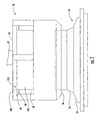
FIG. 1 is a cross-sectional and partial schematic view of portions of a juice extractor prior to compressing the fruit according to the present invention. -
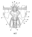
FIG. 2 is a cross-sectional view of a portion of the juice extractor ofFIG. 1 during compression of the fruit. -
FIG. 3 is an enlarged perspective view of the first cutter of the juice extractor ofFIG. 1 . -
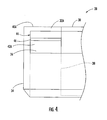
FIG. 4 is an enlarged partial side elevation view of the first cutter ofFIG. 2 . -
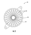
FIG. 5 is a top plan view of the second cup of the juice extractor illustrated inFIG. 1 . -
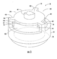
FIG. 6 is a cross-sectional view of the second cup and second cutter associated therewith of the juice extractor illustrated inFIG. 1 . -
FIG. 7 is an enlarged side elevation view of first and second cutters of the juice extractor illustrated inFIG. 1 . -
FIG. 8 is a flow diagram of a method of making a cutter for a juice extractor. -
FIG. 9 is a cross-sectional view of the first and second cutting blades as shown inFIG. 7 with various dimensions marked for clarity of explanation. - The present invention will now be described more fully hereinafter with reference to the accompanying drawings, in which preferred embodiments of the invention are shown. This invention may, however, be embodied in many different forms and should not be construed as limited to the embodiments set forth herein. Rather, these embodiments are provided so that this disclosure will be thorough and complete, and will fully convey the scope of the invention to those skilled in the art. Like numbers refer to like elements throughout.
- Referring initially to
FIGS. 1-4 , ajuice extractor 20 according to the present invention is described. Thejuice extractor 20 illustratively includes first andsecond cups second cups second cups fruit 21 as will be readily understood by those skilled in the art. - The fruit is held in the
second cup 24 with thefirst cup 22 illustratively descending downwardly from above thesecond cup 24 and onto thefruit 21. Illustratively, acam drive mechanism 31 connected to thefirst cup 22 by adrive linkage 29 drives the first cup linearly downward. As will be readily appreciated by those skilled in the art, other orientations of the first andsecond cups second cups - As further illustrated, the
first cup 22 comprises a first plurality offingers 23, and thesecond cup 24 comprises a second plurality offingers 25. Both pluralities offingers fruit 21 as therespective cups - Illustratively, the first plurality of
fingers 23 extends radially outwardly to define a first cup bore 26. Afirst cutter 28 is received within the first cup bore 26 such that it is positioned within a top portion of thefirst cup 22. Thefirst cutter 28 cuts a plug in a top portion of thefruit 21 to permit a separation of the fruit peel from interior portions of the fruit. As will be readily understood by those skilled in the art, this helps prevent thefruit 21 from bursting as it is squeezed between the respective pluralities offingers second cups - The
first cutter 28 illustratively comprises afirst cutter base 30 having threebase openings first cutter 28 may alternately have more than three base openings or it may have as few as one. Thefirst cutter 28 further has afirst cutting blade 34 extending outwardly from thefirst cutter base 30. Illustratively, thefirst cutting blade 34 has a cylindrical shape and a beveled cutting edge. Thefirst cutting blade 34, in extending outwardly from thefirst cutter base 30, defines aninterior passageway 36. Theinterior passageway 36, as shown, is in communication with thebase openings - The
interior passageway 36, through which debris such as fruit peel is released, lends thefirst cutter 28 distinct advantages over conventional cutters having no or only side openings. In contrast to conventional cutters, when thefirst cutter 28 of the present invention cuts into thefruit 21, the fruit peel and other debris is much less likely to become trapped or wedged therein. Instead, under the pressure that results as the first andsecond cups fruit 21 therebetween, the debris is pushed along and out theinterior passageway 36. Specifically, if thefirst cup 22 is oriented above thesecond cup 24 and descends onto thefruit 21, the resulting pressure forces the debris upwardly and out from the first cutter 28 (as indicated by thearrows 27 inFIG. 2 ). - Illustratively, each of the
base openings first cutter 28 opens outwardly to a periphery defined byadjacent base portions interior passageway 36. Additionally, thefirst cutting blade 34 has threeblade openings blade opening base openings interior passageway 36. - Optionally, the
first cutter 28 may include a core 38 that extends outwardly from thefirst cutter base 30 so that the core is positioned within thefirst cutting blade 34. As shown, the optionally includedcore 38 within the first cutting blade 32 is in a spaced relation from the first cutting blade. - Additionally, the
first cutter 28 may optionally includedebris deflectors 44 adjacent thefirst cutter base 30. As illustrated, eachdebris deflector 44 has a pointededge 46 directed toward theinterior passageway 36. Ablade opening 42A in communication with abase opening 32A defines an L- shaped support leg that connects together thefirst cutter base 30 and thefirst cutting blade 34. Thedebris deflector 44 is illustratively adjacent an inner portion of an L-shaped support leg as shown. - Referring additionally now to
FIGS. 5-7 , another aspect of thejuice extractor 20 relative to quality and yield is now described. Thesecond cup 24 illustratively comprises aring base 50 defining a second cup bore 52. The second plurality offingers 25 extends outwardly from thering base 50. - Illustratively, the
second cup 24 further mounts asecond cutter 54 within the second cup bore 52. Thesecond cutter 54 illustratively includes asecond cutting blade 56. As perhaps best shown inFIG. 7 , thesecond cutting blade 56 is sized so that it can be received within theinterior passageway 36 of thefirst cutter 28. - As also illustrated, a
flange 58 extends outwardly from thesecond cutting blade 56 to mount thesecond cutter 54 in the second cup bore 52. Theflange 58 is illustratively at a level flush with adjacent portions of thering base 50. As will be readily understood by those skilled in the art theflange 58 may also be at a level above thering base 50. Theflange 58 serves to prevent cut and separated fruit peel, including the peel ring resulting from the cutting of plugs in thefruit 21, from becoming mixed in with the internal portions squeezed from the fruit by the first andsecond cups flange 58 enhances juice quality by lessening the amount of peel oil that would otherwise be added to the juice during squeezing. - The optionally included
debris deflectors 44, illustratively having pointededges 46, may cooperate with theflange 58 by further segmenting the fruit peel and deflecting it away from the first andsecond cutters fruit 21. Again, the deflection of the peel ring away from the internal portions squeezed from thefruit 21 reduces the amount of peel oil in the juice ultimately produced, thereby enhancing juice quality without reducing juice yield. - A
shaft 60 illustratively extends outwardly from thefirst cutter base 30 opposite thefirst cutting blade 34. Theshaft 60 may secure thefirst cutter 28 to thedrive linkage 29 connected to thecam drive mechanism 31 that illustratively drives thefirst cup 22 down onto thefruit 21 during juice extraction. - Referring again to
FIGS. 1 and2 in particular, thefruit 21 is squeezed as thecam drive mechanism 31 drives thefirst cup 22 together with thesecond cup 24. Thefirst cutter 28 cuts a top plug in the fruit as thefirst cup 22 moves against thefruit 21. Thefruit 21 is also forced against thesecond cutting blade 56, which cuts a bottom plug into a bottom portion of thefruit 21. As a result of increasing pressure during the extraction process, the internal portions 62 of thefruit 21 are forced through the bottom portion plug and into aprefinisher tube 64. Separated fruit peel is discharged between thefirst cup 22 and thefirst cutter 28. As detailed above, any fruit peel or debris within thefirst cutter 28 is released through theinterior passageway 36. - As the internal portions 62 of the
fruit 21 are extracted, they move into aprefinisher tube 64. When extraction is complete, anorifice tube 66 moves upward from below theprefinisher tube 64 creating pressure on the contents therein, which causes extracted juice to flow out through holes in the prefinisher tube and into ajuice manifold 68. The release of fruit peel and other debris through theinternal passageway 36 and its deflection by theflange 58 prevents the debris from mixing with the internal portions of thefruit 21. Accordingly, the quality of the extracted juice is higher. - An additional aspect relates to a method of making a
cutter 28 for use with ajuice extractor 20 that includes first andsecond cups flow chart 70 ofFIG. 8 includes, after starting (Block 72), providing acutter base 30 that has at least onebase opening cutter base 30 having at least onebase opening adjacent base portions - The method further illustratively includes, at
Block 76, connecting acutting blade 34 to extend outwardly from thecutter base 28 to thereby define aninterior passageway 36 in communication with the at least onebase opening cutting blade 34 with at least oneblade opening base opening - Illustratively, the method further includes at
Block 78, optionally connecting a core 38 to extend outwardly from thecutter base 28 so that it is positioned within the cutting blade in spaced relation therefrom. The method also illustratively includes, atBlock 80, optionally connecting at least onedebris deflector 44 to thecutter base 30. The connecting of at least onedebris deflector 44 may optionally entail connecting at least one debris deflector that has a pointededge 46 directed along theinterior passageway 36. - Turning now additionally to
FIG. 9 other features of theextractor 20 relating to enhancing juice quality and yield are now described. The firstcylindrical cutting blade 34 may preferably have an inner diameter ID1 in a range of about 25.1 to 25.7 mm (0.990 to 1.010 inches), and a wall thicknessT1 in a range of about 1.72 to 2.23 mm (0.068 to 0.088 inches). The secondcylindrical cutting blade 56 may preferably have an outer diameter OD2 to be received within the inner diameter ID1 of the firstcylindrical cutting blade 34. These particular component sizes have been found to produce a desired relatively high yield and juice quality. - Prior art attempts at trying various sizes of the cutters, etc. has not produced the desired high juice yield and high juice quality unexpectedly produced by these particular component dimensions. Indeed, it is theorized, without Applicants wishing to be bound thereto, that at least some of the unexpected improvement comes from more efficiently clearing the peel from the inner fruit as a result of the thinner walled
cylindrical cutting blade 34 of thefirst cutter 28 in accordance with this aspect of the invention, and as compared to the thicker walled blade as used in the prior art. It is also theorized, without Applicants wishing to be bound thereto, that the inner diameter of thefirst cutting blade 34 also cooperates with the 22.23 mm (seven-eighths inch)second cutter 54 to provide high yield and without excessive peel oil entering the juice during extraction. - The inner diameter ID1 of the first
cylindrical cutting blade 34 may more preferably be in a range of about 25.32 to 25.48 mm (0.997 to 1.003 inches). In addition, the wall thicknessT1 of the firstcylindrical cutting blade 34 may more preferably be in a range of about 1.91 to 2.06 mm (0.075 to 0.081 inches). These values are based on desired tolerances of + 0.076 mm (+ 0.003 inch), for example, although other tolerance values are also contemplated by the present invention as will be appreciated by those skilled in the art. - The second
cylindrical cutting blade 56 may preferably have an inner diameter ID2 in a range of about 21.5 to 23.0 mm (0.845 to 0.905 inches), and, more preferably, in a range of about 22.3 to 22.5 mm (0.878 to 0.884 inches). The secondcylindrical cutting blade 56 may also have an outer diameter OD2 less than about 24.6 mm (0.970 inches). For example, the outer diameter OD2 may range from about 24.5 to 24.6 mm (0.963 to 0.970 inches). Accordingly, the wall thickness T2 of thesecond cutting blade 56 may be in a range of about 1.01 to 1.17 mm (0.040 to 0.046 inches). - The peel clearance PC may be in a range of about 1.98 to 2.79 mm (0.078 to 0.110 inches) for most oranges, for example. Of course, other values of peel clearance may also be used as will be appreciated by those skilled in the art.
- The spacing of adjacent finger portions of the second cup from the second cutter may be in the conventional range of about 4.98 to 5.13 mm (0.196 to 0.202 inches), for example. In addition, the
prefinisher tube 64 andorifice tube 66 as described above may also be sized appropriately for thesecond cutter 56 having the inner and outer diameters as noted as will be readily appreciated by those skilled in the art without requiring further discussion. - Other aspects relating to the
extractor 20 and associated methods are disclosed in copending application entitled "JUICE EXTRACTOR INCLUDING CUTTER COMPONENTS FOR ENHANCED QUALITY AND YIELD PERFORMANCE AND ASSOCIATED METHODS" filed concurrently herewith on October 15, 2002, publication no.US20040069159A . Accordingly, many modifications and other embodiments of the invention will come to the mind of one skilled in the art having the benefit of the teachings presented in the foregoing descriptions and the associated drawings. Therefore, it is to be understood that the invention is not to be limited to the specific embodiments disclosed, and that other modifications and embodiments are intended to be included within the scope of the appended claims.
Claims (19)
- A cutter (28) for use with a juice extractor (20) including first and second cups (22, 24) being relatively moveable for compressing fruit (21) therebetween during juice extraction, the cutter comprising:a cutter base (30) and a cutting blade (34) extending therefrom,characterised in that the cutter base has at least one base opening (32A, 32B, 32C) therein;
and the cutting blade extends outwardly from said cutter base to define an interior passageway (36) in communication with the at least one base opening to release debris therethrough. - A cutter (28) according to Claim 1 further comprising a core (38) extending outwardly from said cutter base (30) and positioned within said cutting blade (34) in spaced relation therefrom.
- A cutter (28) according to Claim 1 or 2 wherein the at least one base opening (32A, 32B, 32C) opens outwardly to a periphery defined by adjacent base portions (40A, 40B, 40C).
- A cutter (28) according to any preceding Claim wherein said cutting blade has at least one blade opening (42A, 42B, 42C) therein.
- A cutter (28) according to Claim 4 wherein the at least one blade opening (42A, 42B, 42C) is in communication with the at least one base opening (32A, 32B, 32C).
- A cutter (28) according to any preceding Claim further comprising at least one debris deflector (44) carried by or adjacent said cutter base (30).
- A cutter (28) according to Claim 6 wherein said at least one debris deflector (44) has a pointed edge (46) directed along the interior passageway.
- A cutter (28) according to Claim 6 or 7 wherein said cutting blade has at least one blade opening (42A, 42B, 42C) therein and in communication with the at least one base opening (32A, 32B, 32C) to define at least one L-shaped support leg connecting said cutter base (30) and said cutting blade (34) together; and
wherein said at least one debris deflector (44) is adjacent an inner portion of the at least one L-shaped support leg. - A cutter (28) according to any preceding Claim wherein said cutting blade (34) has a cylindrical shape and a beveled cutting edge.
- A cutter (28) according to Claim 1 wherein said cutter further comprises a shaft (60) extending outwardly from said cutter base (30) opposite said cutting blade (34).
- A juice extractor (20) comprising first and second cups (22, 24) and a first cutter (28) according to any one of claims 1- 9.
- A juice extractor (20) according to Claim 11 wherein said second cup (24) comprises a ring base (50) defining a second cup bore (52), and a plurality of fingers (25) extending outwardly from said ring base; and further comprising a second cutter (54) including a second cutting blade (56) sized to be received within the interior passageway (36) of said first cutter (28), and a flange (58) extending outwardly from said second cutting blade and mounting said second cutter in the second cup bore.
- A juice extractor (20) according to Claim 12 wherein said flange (58) is at a level flush with or above adjacent portions of said ring base (50).
- A juice extractor (20) according to Claim 11, 12 or 13 wherein said first cup (22) comprises a plurality of fingers (23) extending radially outward and defining a first cup bore (26).
- A juice extractor (20) according to Claim 14 wherein the first cup bore (26) receives said first cutter (28) therein.
- A juice extractor (20) according to any one of Claims 11 to 15 wherein said first and second cups (22, 24) are relatively moveable along a substantially linear reciprocal path of travel.
- A juice extractor (20) comprising:first and second cups (22, 24) being relatively moveable along a substantially linear reciprocal path of travel;said first cup comprising a first plurality of fingers (23) extending radially outwardly and defining a first cup bore (26);said second cup comprising a ring base (50) defining a second cup bore (52), and a second plurality of fingers (25) extending outwardly from said ring base and intermeshing with said first plurality of fingers to compress a fruit (21) therebetween during juice extraction;a first cutter (28) comprising a first cutter base (30), and a first cutting blade (34) extending outwardly from said first cutter base (30); anda second cutter (54) comprising a second cutting blade (56) sized to be received within said first cutter, characterised in that the second cutter comprises a flange (58) extending outwardly from said second cutting blade (56) and mounting said second cutter in the second cup bore;said flange being at a level flush with or above adjacent portions of said ring base.
- A juice extractor (20) according to Claim 17 further comprising a core (38) extending outwardly from said first cutter base (30) and positioned within said first cutting blade (34) in spaced relation therefrom.
- A juice extractor (20) according to Claim 17 or 18 wherein said first cutting blade (34) has a cylindrical shape and beveled cutting edge.
Applications Claiming Priority (3)
| Application Number | Priority Date | Filing Date | Title |
|---|---|---|---|
| US271249 | 1988-11-14 | ||
| US10/271,249 US6805043B2 (en) | 2002-10-15 | 2002-10-15 | Juice extractor with enhanced quality and yield performance and methods of making same |
| PCT/US2003/026613 WO2004034823A1 (en) | 2002-10-15 | 2003-08-25 | Juice extractor with enhanced quality and yield performance and methods of making same |
Publications (2)
| Publication Number | Publication Date |
|---|---|
| EP1578216A1 EP1578216A1 (en) | 2005-09-28 |
| EP1578216B1 true EP1578216B1 (en) | 2009-07-01 |
Family
ID=32069113
Family Applications (1)
| Application Number | Title | Priority Date | Filing Date |
|---|---|---|---|
| EP03808959A Expired - Lifetime EP1578216B1 (en) | 2002-10-15 | 2003-08-25 | Juice extractor with enhanced quality and yield performance and methods of making same |
Country Status (9)
| Country | Link |
|---|---|
| US (1) | US6805043B2 (en) |
| EP (1) | EP1578216B1 (en) |
| AR (2) | AR041572A1 (en) |
| AU (1) | AU2003265666B2 (en) |
| BR (1) | BR0314887B1 (en) |
| ES (1) | ES2327228T3 (en) |
| MX (1) | MXPA05004083A (en) |
| WO (1) | WO2004034823A1 (en) |
| ZA (1) | ZA200502880B (en) |
Families Citing this family (7)
| Publication number | Priority date | Publication date | Assignee | Title |
|---|---|---|---|---|
| US8047130B2 (en) * | 2007-04-13 | 2011-11-01 | Carlos Mendes Neto | Opposing paired peeling cups for fruit juice extraction devices, and said devices comprising said cups |
| WO2011089278A1 (en) * | 2010-01-20 | 2011-07-28 | Fomesa Agroindustrial, S.L. | An upper cutter for citrus rinds for a juicer and a set formed by an upper cutter and a lower cutter |
| CN102283423B (en) * | 2011-07-06 | 2015-06-24 | 辛梅松 | Full-automatic drum type fruit grain separation orange squeezer |
| CN107529427A (en) * | 2013-05-10 | 2018-01-02 | 竹斯柔公司 | Squeeze the juice system |
| TWM477236U (en) * | 2013-09-12 | 2014-05-01 | Ten Sheng Assorted Houseware Co Ltd | Combined juice extracting device |
| US20150201666A1 (en) * | 2014-01-17 | 2015-07-23 | John Bean Technologies Corporation | Extractor for producing enhanced quality pulp and associated methods |
| CN108523619B (en) * | 2018-04-30 | 2021-05-04 | 赣州市倞华菲尔雪食品有限公司 | Peel opening device |
Family Cites Families (19)
| Publication number | Priority date | Publication date | Assignee | Title |
|---|---|---|---|---|
| US2649730A (en) * | 1949-02-16 | 1953-08-25 | Fmc Corp | Method of and apparatus for extracting juice from whole citrus fruit |
| US2780988A (en) * | 1953-02-24 | 1957-02-12 | Fmc Corp | Method of and apparatus for processing whole fruit |
| US3053170A (en) * | 1960-11-17 | 1962-09-11 | Ralph W Cook | Citrus fruit peel shredder |
| US3236175A (en) * | 1964-06-29 | 1966-02-22 | Fmc Corp | Apparatus for separating liquid from solid material |
| US3717084A (en) * | 1971-01-18 | 1973-02-20 | Fmc Corp | Water spray ring for citrus fruit processing apparatus |
| US3736865A (en) * | 1971-04-19 | 1973-06-05 | Fmc Corp | Fruit processing apparatus |
| US4154163A (en) * | 1977-05-23 | 1979-05-15 | Fmc Corporation | CCX extractor |
| US4376409A (en) * | 1980-08-11 | 1983-03-15 | Fmc Corporation | Citrus fruit juice extractor |
| US4700620A (en) * | 1986-02-10 | 1987-10-20 | Fmc Corporation | Citrus juice extractor |
| US4871569A (en) * | 1988-05-17 | 1989-10-03 | The Procter & Gamble Company | Dual-stream juice processing for recovering juice solids from extractor core material |
| US4951563A (en) * | 1988-09-06 | 1990-08-28 | Warren Loyd C | Fully automatic citrus fruit juice extractor |
| US4922813A (en) * | 1989-02-02 | 1990-05-08 | Fmc Corporation | Low cost quick insert citrus strainer tube |
| US5070778A (en) * | 1989-12-06 | 1991-12-10 | Fmc Corporation | Juice extractor having modified plug-forming cutter |
| US5170700A (en) * | 1990-12-14 | 1992-12-15 | Fmc Corporation | Fluted column for juice extractor |
| BR9502244A (en) * | 1995-06-19 | 1995-11-07 | Neto Carlos Mendes | Arrangement in a fruit juice extraction machine |
| US5992311A (en) * | 1998-05-29 | 1999-11-30 | Fmc Corporation | Juice extractor with hydraulic control of extraction back pressure |
| US5970861A (en) * | 1998-05-29 | 1999-10-26 | Fmc Corporation | Juice extractor with safety release member |
| US6293189B1 (en) * | 2000-03-13 | 2001-09-25 | Tropicana Products, Inc. | Juice extractor |
| US6568319B2 (en) * | 2001-05-14 | 2003-05-27 | Fmc Technologies, Inc. | Juice extractor with improved two-piece orifice tube |
-
2002
- 2002-10-15 US US10/271,249 patent/US6805043B2/en not_active Expired - Lifetime
-
2003
- 2003-08-25 AU AU2003265666A patent/AU2003265666B2/en not_active Ceased
- 2003-08-25 BR BRPI0314887-4A patent/BR0314887B1/en active IP Right Grant
- 2003-08-25 MX MXPA05004083A patent/MXPA05004083A/en active IP Right Grant
- 2003-08-25 ES ES03808959T patent/ES2327228T3/en not_active Expired - Lifetime
- 2003-08-25 WO PCT/US2003/026613 patent/WO2004034823A1/en not_active Application Discontinuation
- 2003-08-25 EP EP03808959A patent/EP1578216B1/en not_active Expired - Lifetime
- 2003-10-09 AR ARP030103683A patent/AR041572A1/en not_active Application Discontinuation
-
2005
- 2005-04-08 ZA ZA200502880A patent/ZA200502880B/en unknown
-
2007
- 2007-06-14 AR ARP070102604A patent/AR063197A2/en not_active Application Discontinuation
Also Published As
| Publication number | Publication date |
|---|---|
| AU2003265666B2 (en) | 2008-09-18 |
| EP1578216A1 (en) | 2005-09-28 |
| US6805043B2 (en) | 2004-10-19 |
| MXPA05004083A (en) | 2005-06-08 |
| BR0314887A (en) | 2005-08-02 |
| AR063197A2 (en) | 2009-01-14 |
| ES2327228T3 (en) | 2009-10-27 |
| AU2003265666A1 (en) | 2004-05-04 |
| AR041572A1 (en) | 2005-05-18 |
| US20040069162A1 (en) | 2004-04-15 |
| WO2004034823A1 (en) | 2004-04-29 |
| BR0314887B1 (en) | 2013-01-22 |
| ZA200502880B (en) | 2006-10-25 |
Similar Documents
| Publication | Publication Date | Title |
|---|---|---|
| US5070778A (en) | Juice extractor having modified plug-forming cutter | |
| US4376409A (en) | Citrus fruit juice extractor | |
| ZA200502880B (en) | Juice extractor with enhanced quality and yield performance and methods of making same | |
| US6568319B2 (en) | Juice extractor with improved two-piece orifice tube | |
| US3736865A (en) | Fruit processing apparatus | |
| US4700620A (en) | Citrus juice extractor | |
| DE202009018741U1 (en) | Electric household appliance for the preparation of juice | |
| US20150201666A1 (en) | Extractor for producing enhanced quality pulp and associated methods | |
| AU2014378034B2 (en) | Juice extraction devices with hollow juice extraction screw | |
| US6923112B2 (en) | Juice extractor including cutter components for enhanced quality and yield performance and associated methods | |
| US7487721B2 (en) | Orifice tube with enhanced angle and associated methods | |
| US3053170A (en) | Citrus fruit peel shredder | |
| KR20170030628A (en) | Food preparation device for extracting juices by pressing | |
| CN210055605U (en) | Squeezing module of juicer | |
| WO1997017855A1 (en) | Separator screen and screening method | |
| EA003150B1 (en) | Method for the production of juice from fruits such as pomegranates | |
| CN210055606U (en) | Squeezing module of juicer | |
| US20040221748A1 (en) | Juice extractor with orifice tube | |
| KR960000061Y1 (en) | Machine for extracting juice | |
| JPH0795937B2 (en) | Juice squeezer and method | |
| US4509418A (en) | Surface for supporting cut fruit in fruit juicer | |
| BRPI0318986B1 (en) | juice extractor and method for making a cutter | |
| DE202024100201U1 (en) | Food processing device | |
| JPS59207116A (en) | Cooking machine | |
| CN111317146A (en) | Full-automatic orange juice feeding and squeezing device for food processing |
Legal Events
| Date | Code | Title | Description |
|---|---|---|---|
| PUAI | Public reference made under article 153(3) epc to a published international application that has entered the european phase |
Free format text: ORIGINAL CODE: 0009012 |
|
| 17P | Request for examination filed |
Effective date: 20050513 |
|
| AK | Designated contracting states |
Kind code of ref document: A1 Designated state(s): AT BE BG CH CY CZ DE DK EE ES FI FR GB GR HU IE IT LI LU MC NL PT RO SE SI SK TR |
|
| AX | Request for extension of the european patent |
Extension state: AL LT LV MK |
|
| DAX | Request for extension of the european patent (deleted) | ||
| RBV | Designated contracting states (corrected) |
Designated state(s): ES GB IT |
|
| REG | Reference to a national code |
Ref country code: DE Ref legal event code: 8566 |
|
| GRAP | Despatch of communication of intention to grant a patent |
Free format text: ORIGINAL CODE: EPIDOSNIGR1 |
|
| RAP1 | Party data changed (applicant data changed or rights of an application transferred) |
Owner name: JOHN BEAN TECHNOLOGIES CORPORATION |
|
| GRAS | Grant fee paid |
Free format text: ORIGINAL CODE: EPIDOSNIGR3 |
|
| GRAA | (expected) grant |
Free format text: ORIGINAL CODE: 0009210 |
|
| AK | Designated contracting states |
Kind code of ref document: B1 Designated state(s): ES GB IT |
|
| REG | Reference to a national code |
Ref country code: GB Ref legal event code: FG4D |
|
| REG | Reference to a national code |
Ref country code: ES Ref legal event code: FG2A Ref document number: 2327228 Country of ref document: ES Kind code of ref document: T3 |
|
| PLBE | No opposition filed within time limit |
Free format text: ORIGINAL CODE: 0009261 |
|
| STAA | Information on the status of an ep patent application or granted ep patent |
Free format text: STATUS: NO OPPOSITION FILED WITHIN TIME LIMIT |
|
| 26N | No opposition filed |
Effective date: 20100406 |
|
| PGFP | Annual fee paid to national office [announced via postgrant information from national office to epo] |
Ref country code: IT Payment date: 20160822 Year of fee payment: 14 |
|
| PG25 | Lapsed in a contracting state [announced via postgrant information from national office to epo] |
Ref country code: IT Free format text: LAPSE BECAUSE OF NON-PAYMENT OF DUE FEES Effective date: 20170825 |
|
| PGFP | Annual fee paid to national office [announced via postgrant information from national office to epo] |
Ref country code: GB Payment date: 20220707 Year of fee payment: 20 Ref country code: ES Payment date: 20220902 Year of fee payment: 20 |
|
| REG | Reference to a national code |
Ref country code: ES Ref legal event code: FD2A Effective date: 20230901 |
|
| REG | Reference to a national code |
Ref country code: GB Ref legal event code: PE20 Expiry date: 20230824 |
|
| PG25 | Lapsed in a contracting state [announced via postgrant information from national office to epo] |
Ref country code: GB Free format text: LAPSE BECAUSE OF EXPIRATION OF PROTECTION Effective date: 20230824 Ref country code: ES Free format text: LAPSE BECAUSE OF EXPIRATION OF PROTECTION Effective date: 20230826 |