Technical Field
The invention relates to a carrier of a distribution point in
the field of telecommunications as well as a distribution
point comprising at least one carrier.
Background
In the field of telecommunications numerous customers are
connected with the switch of a telecommunications company via
telecommunication lines. The customers can also be called
subscribers. The switch is also called an exchange. Between
the subscriber and the switch, sections of the
telecommunication lines are connected with telecommunications
modules. The telecommunications modules establish an
electrical connection between a wire, which is connected at
the telecommunications module at a first side, and another
wire, which is connected to the telecommunications module at
a second side. The telecommunications modules may comprise a
housing in which wire guides are integrated. Furthermore,
one or more printed circuit boards can be integrated with the
telecommunications modules and can extend from the housing of
a telecommunications module.
The described telecommunications modules can be located at
any type of distribution point. A typical distribution point
is the main distribution frame located in the central office
of a telecommunications company. However, further
distribution points are known in the art, such as
distribution points outside the central office, which e.g.
serve a number of streets or houses. Also office buildings
or floors within buildings can have distribution points.
The distribution points usually comprise carriers of a
suitable type, such as racks or sub-racks, to which the
telecommunications modules can be mounted. These carriers
can comprise a so-called back-mount frame, which has a
structure that is adapted to a particular type of
telecommunications module. The back-mount frames can
comprise elongate, trough-like structures comprising parallel
walls, to which telecommunications modules can be mounted,
e.g. by latching mechanisms. The walls can comprise openings
at regular intervals so as to define a predetermined spacing,
or pitch, for the telecommunications modules mounted thereon.
Furthermore, the applicant's subsidiary, Quante AG, based in
Germany, offers a mounting system called Flexirail which is
constituted by two parallel profiles having a cross-sectional
configuration which is suitable for releasably mounting
telecommunications modules thereon.
EP 0 498 790 A1 discloses a modular rack for accommodating
printed circuit boards. Sub-assemblies are made of
horizontal rods, which are connected by side plates.
Adjacent assemblies are connected by the side plates.
Telecommunications modules as described above are not
mountable to the disclosed structure.
WO 98/35413 describes a modular general-purpose distribution
frame comprising plural hollow bodies forming a skeleton of
the frame.
Finally, US 2003/0133272 A1 discloses an apparatus and method
for facilitating capacity expansion of a modular frame. The
apparatus comprises a housing and at least two mounting
brackets, to which connection blocks can be mounted by
utilizing block-mounting brackets. All of the above
described racks and frames do not allow an easy change or
extension of the structure thereof.
Summary of the Invention
The invention provides a carrier of a distribution point in
the field of telecommunications with increased versatility.
Furthermore, this versatility is realized in a distribution
point comprising at least one carrier provided by the
invention.
The carrier of a distribution point in the field of
telecommunications has a generally open, frame-like
structure. The carrier can also be called a mounting
structure and is intended to cover any structure or assembly,
which allows telecommunications modules to be mounted
thereon. The carrier can be a part of a rack, which is
located in a distribution point in the field of
telecommunications. In this context, a rack is considered a
structure which can "stand alone", i.e. does typically not
require a further mounting structure. As mentioned, the
carrier described herein can be part of such a rack.
Furthermore, it is generally possible for the carrier
described herein that it also stands alone and provides an
integrated structure for mounting telecommunications modules
thereon.
The carrier can be provided at any type of distribution point
in the field of telecommunications, e.g. a main distribution
frame located in the central office of the telecommunications
company, any type of intermediate distribution frame, an
outside distribution point such as a cabinet located at the
curb side or a distribution point provided in a building,
such as an office building or on a particular floor of an
office building.
The frame-like, generally open structure of the carrier is
realized by at least three substantially parallel bars, which
are located in at least two planes. The bars can also be
called rods and encompass any elongate and, as regards the
cross-section, compact element. The bars can generally be
seen as mounting elements, which extend in one direction,
thus forming an elongated structure. For example, the cross-section
of each of the bars can be profiled in a manner
suitable to mount telecommunications modules thereon.
Furthermore, the cross-section of the bars can be adapted to
mount one or more adapters or intermediate elements thereon.
These adapters and/or intermediate elements may also have an
elongate shape corresponding to the general structure of the
bars. In such a modification telecommunications modules can
be mounted to the adapter or intermediate elements.
The at least three substantially parallel bars of the carrier
can be of the same or of different cross-sections. As the
bars are located in at least two planes, their cross-section
can be adapted to the particular location where a particular
bar is used. In this context, the at least two planes which
are defined by the at least three bars can be seen in a
cross-sectional view at a right angle with regard to the
extension of the bars. In such a cross-section, there will
be typically two bars which define a front plane.
Correspondingly, typically two bars will define a backplane,
which will usually be substantially parallel with the front
plane. As described in more detail below, due to different
types of objects, amongst others telecommunications modules,
which are to be mounted to the bars, the bars of the front
plane can have a cross-section which differs from that of the
backplane. However, the cross-section of all bars can be
identical. In this case, the manufacturing costs can be kept
at a lower level due to a high degree of standardization.
To provide an integral carrier, the bars are maintained in a
fixed relationship to each other. In particular, they can be
directly, or indirectly connected with each other. The
maintaining of the bars in a fixed relationship to each other
can be realized by any suitable structure. For example, one
or more plate-like elements can be used to connect the bars
with each other so as to define a generally open, frame-like
structure, which will then be closed at at least one side by
the described plate. However, the bars can also be connected
with each other by further bars or rods extending
substantially perpendicular to the bars, which are to be
connected to each other.
Finally, at least one of the bars is adapted to mount
telecommunications modules thereon. In a specific embodiment
of the carrier described herein two substantially parallel
bars cooperate to define a mounting structure for
telecommunications modules. As mentioned above, the bars can
advantageously have a constant cross-section. Instead or in
addition thereto an adapter or intermediate element, which
may have substantially the same length as the bar, can be
attached to the bar. Advantageously, such an adapter or
intermediate element also has a constant cross-section
throughout. This provides enhanced flexibility for mounting
telecommunications modules for the following reasons.
Firstly, the carrier having bars as described above does not
define a predetermined pitch for mounting telecommunications
modules. Rather, telecommunications modules can be mounted
at any desired location along the bars and can particularly
be moved along the bars by sliding them relative to the bars.
Consequently, the capacity of the carrier is not limited by a
predetermined pitch, but the carrier can be equipped with as
many telecommunications modules as it can accommodate. Also
in a situation when the configuration of telecommunications
modules is to be changed, the carrier described herein
permits great versatility. As described in more detail
below, wire guides can be mounted to the carrier in addition
to and preferably between telecommunications modules. If a
need for wire guides arises, two adjacent telecommunications
modules merely have to be moved apart from each other along
the bars for a sufficient distance so as to mount wire guides
in between. Furthermore, as there are different types of
wire guides, one type of wire guide can be replaced for a
different type of wire guide, when the need arises.
Furthermore, the carrier is flexible with regard to its
length, i.e. its extension in the direction of the bars. As
the size of the carrier is essentially only limited by the
length of the bars used, these can be provided at any
suitable or desired length. In particular, this length is in
no manner dependent on a particular pitch. Rather, any
length can be realized so as to provide a carrier suitable
for any number of telecommunications modules and/or wire
guides and/or further components. As an example, the
telecommunications module disclosed in the WO 2003/061303 can
be mounted to the carrier. In particular, the structure of
this known telecommunications module in general, and with
regard to the wire guides, can be used as a reference, which
is incorporated herein, for the structures described herein.
As regards the versatility, it should be emphasized that the
telecommunications modules can be used without any wire
guides. Further, one wire guide comprising any suitable
number of wire guiding channels can be combined with a
telecommunications module. Two wire guides as described
above can be provided adjacent the telecommunications module
on each side thereof. Furthermore, two wire guides can be
arranged on the same side of a telecommunications module.
Finally, plural wire guides can be arranged adjacent any
desired sides of a particular telecommunications module.
It is, furthermore, beneficial for the carrier that the bars
are arranged so as to define at least two planes. These
planes can be used to provide defined mounting locations for
specific parts of telecommunications modules or further
components to be mounted thereon. As mentioned above,
telecommunications modules can be directly or indirectly
mounted to two bars defining a front plane. Two further
bars, defining a backplane substantially parallel to the
front plane, can be used to hold a printed circuit board.
The printed circuit board can be provided with connectors and
suitable components. For example, printed circuit boards can
be connected with the connectors, on the one hand, and the
telecommunications modules at their rear side, on the other
hand. Thus, an assembly of plural telecommunications modules
can be connected with each other in a flexible and reliable
manner. These advantages are obtained by the versatile
carrier having a modular structure being comprised of very
few basic elements, such as the bars and those components
connecting the bars with each other. Finally, that bar or
those bars which is/are intended to mount telecommunications
modules thereon can be constituted by a bar such as the
product Flexirail offered by 3M/Quante AG, of Neuss, Germany.
Although the carrier can have any suitable number of bars in
at least two planes, it is currently preferred that four bars
are provided which define, in cross-section, a rectangular
structure. As mentioned above, the cross-section is obtained
from a section perpendicular to the extension of the bars.
In the described rectangular structure two planes are
provided which allow flexible mounting of different types of
components such as telecommunications modules, on the one
hand, and a printed circuit board, on the other hand, at
different depths and/or levels.
In general, the bars can be of any cross-section and the
mounting of the telecommunications modules can be adapted to
allow the telecommunications modules to be mounted to bars of
a certain cross-section. In particular, the bars can also
have a profiled cross-section comprising suitable projections
and/or undercuts for cooperating with structures like latch
hooks and/or bulges of components, which are to be mounted to
the bars. Telecommunications modules can be provided with
suitable latch hooks. Furthermore, an adapter-bar or any
other suitable intermediate element can be provided with one
or more bulges cooperating with undercuts of the bars of the
carrier. Thus, telecommunications modules can be directly
attached to the bars. Furthermore, telecommunications
modules can be indirectly attached to the bars by attaching
one or more adapters to the bars, and mounting the
telecommunications modules to the one or more adapters.
The bars can be maintained in a fixed relationship to each
other, in particular, indirectly connected with each other by
one or more plates or side walls. The plates can extend
perpendicular to the direction of the bars and provide a
simple and efficient connection of the bars as well as a type
of closure at the sides of the carrier. Generally, the front
and back as well as the top and bottom of the carrier are
defined by the bars and remain open, and plates or walls are
preferably used only at/as sides. The bars can, e.g. be
connected with the plates by screws or clamps.
In practice, the carrier can comprise at least one adapter,
which is attachable to one or more of the bars and adapted to
mount telecommunications modules thereon. The adapter can
have an elongate structure and be of substantially the same
length as the bars. The adapter can have one or more
projections or bulges which can cooperate with undercuts in
the cross-section of the bars so as to allow the mounting
thereof. Thus, the bar is appropriately shaped or profiled
to allow the adapter to be mounted thereon. As an
alternative, the adapter can have an appropriate shape or
profile to allow the mounting thereof to the bar. Finally,
any type of cooperating structure, both on the bar and the
adapter, can be used. It should also be mentioned that there
can be more than one adapter or intermediate element provided
on a single bar to allow the mounting of telecommunications
modules to one of the adapters or intermediate elements.
In particular, the adapter can be mounted to the bar by being
slid into a profiled section of the bar, e.g. so as to
accommodate the bulges and/or projections of the adapter in
the undercut of the bar. The adapter can, as seen in the
cross-section, provide a suitable projection or flange so as
to allow telecommunications modules having latch hooks to be
mounted thereon.
The carrier can comprise one or more printed circuit boards.
One printed circuit board can be provided at a rear side of
the carrier so as to constitute a so-called backplane. The
printed circuit can be mounted directly to one or more bars.
Alternatively, adapters or intermediate elements, as
described above, can be used for this purpose. In the case
of a backplane, the printed circuit board extends essentially
parallel with the bars. This allows plural
telecommunications modules, which can have integrated printed
circuit boards for various purposes, to be connected with
each other. In particular, portions of the
telecommunications modules or the printed circuit boards
thereof, can be connected with connectors, which can be
provided on the printed circuit board constituting the
backplane. As apparent, one or more printed circuit boards
can thus be provided in an orientation substantially
perpendicular to the extension of the bars. As described
below, these can be guided by suitable guides. In
particular, the last mentioned printed circuit boards can be
used to carry splitter circuits. Splitter circuits are now
widely used in ADSL-technology. This technology allows at
least two different signals to be transmitted by a single
line. This is achieved by transmitting the different signals
at different frequencies along the same line. The signals
are combined at a particular point in the telecommunications
line. The combined signal is split at another point. In
particular, at the subscriber side, voice and data signals,
which are separate, are combined and sent to the central
office via the same line. In the central office the combined
signal is split. For the transmission of voice data signals
to the subscriber, separate voice and data signals are
combined at the central office, sent to the subscriber and
split at the subscriber side. After splitting the signal,
the so-called POTS (plain old telephone service) signal can
be used to transmit voice. Furthermore, the remaining parts
of the split signal can be used to transmit data, for
example. The splitters, which are used to split or combine
the signal, can be provided by suitable circuits on printed
circuit boards, which can be accommodated in the carrier, as
described above.
Moreover, printed circuit boards can be used in a
configuration integrated with a telecommunications module or
not, to provide a switch or relay matrix which allows for
test and monitoring access to the contacts of a
telecommunications module as well as to lines connected
therewith. Furthermore, other active electronic parts, such
as a multiplexer or a DSLAM can be integrated with a
telecommunications module. One or more printed circuit
boards can be used in this context. In any case, a further
printed circuit board defining a backplane can provide a test
bus for accessing selected contacts of selected
telecommunications modules. For further details of such a
test and monitoring access system, reference is made to the
WO 03/079599, the contents of which are incorporated herein
by reference. As mentioned, the one or more printed circuit
boards of the carrier can have one or more connectors to
advantageously establish connections with other components,
such as further printed circuit boards.
The carrier can further comprise at least one guiding element
attachable to at least one of the bars. The guiding elements
can be flexibly mounted to any desired and suitable location
on the bars to provide a guide for a printed circuit board
and/or wire guides as described below. As an alternative,
one or more bars can have guiding elements integrated
therewith.
Thus, the guiding element can be adapted to guide one or more
printed circuit boards so that a guiding element can extend
between two bars in a direction perpendicular to the bars and
can comprise a suitable slit along its extension. A printed
circuit board can be inserted into the slit with its edge and
can thus be guided.
The guiding element can, furthermore, be adapted to guide one
or more wire guides. As will be apparent to those skilled in
the field of telecommunications, wire guides can be
constituted by two plates between which walls are formed so
as to define channel-like structures. These channels extend
from one side which is defined in a particular plane, to
another side defined in a plane substantially perpendicular
to the first mentioned plane. Due to the preferably arch-shaped
structure of the interior walls, wires can be guided
from one side to a second side that is substantially
perpendicular to the first side. In the carrier described
herein, such wires guides can be accommodated in an
orientation with the bars being substantially perpendicular
to the sides of the wire guide. As described above, wire
guides of different types and/or different thicknesses, (in
the direction of the bars) can flexibly be mounted to the
carrier. In particular, the wire guides having arch-shaped
channels, can be used, for example, to guide wires from the
top or the bottom of the carrier to a front side, at which
telecommunications modules are mounted, the contacts of which
are exposed so as to connect the wires therewith. As will be
apparent to those skilled in the art, the channels can be
provided with a curve in any suitable manner. In particular,
they could also be quarter-circular. Turning back to the
guiding elements described above, these can be provided in an
orientation essentially perpendicular to the bars, so as to
guide the described wire guides. A guiding element, which is
adapted to guide both a printed circuit board and a wire
guide, can also be provided.
In particular, the guiding element can be adapted to guide a
printed circuit board and one or more cables in parallel
directions. In other words, a slit, in which a printed
circuit board can be guided by engagement with its edge(s),
can extend in parallel to an opening and/or a passage,
through which cables can be guided.
Furthermore, a guiding element, which can be adapted to guide
a wire guide, can comprise at least one opening. Such an
opening can advantageously be used to allow the insertion of
wires into the channels of the wire guide.
Whereas the carrier described herein can, e.g. by the above-mentioned
guiding elements, be prepared to be provided with
wire guides, to provide the function of guiding the wire in
the carrier described herein, the latter comprises at least
one wire guide integrated therewith.
As will be apparent from above, a distribution point in the
field of telecommunications technology can be provided with
enhanced flexibility by utilizing at least one carrier in one
of the above-described feature combinations and at least one
telecommunications module in order to allow, eventually, the
flexible connection of subscriber lines with the exchange.
Brief description of the drawings
Hereinafter, the invention will be described by several, nonlimiting
examples thereof with reference to the drawings, in
which:
Description of Preferred Embodiments of the Invention
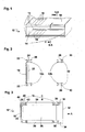
In one embodiment, the carrier 10, as shown in a perspective
view in Fig. 1, generally consists of four bars 12, which are
arranged substantially parallel to each other so as to form a
generally open frame having a rectangular cross-section, as
can be seen from the sectional view of Fig. 2. The bars 12,
which could also be called support bars or rods, are
maintained in a fixed relationship to each other by two side
plates 14, to each of which each bar 12 is connected at an
end thereof. As will be described in more detail below,
guiding elements 16, which are constituted by so-called grid
plates, are mounted to the carrier by being attached to two
bars 12 each. In the embodiment shown, a printed circuit
board 18 is provided at a rear side of the carrier 10 so as
to define a so-called backplane. The carrier having this
general structure can be mounted in a rack or sub-rack of any
type of distribution point so as to allow telecommunications
modules to be mounted thereon as will be described in more
detail below.
Fig. 2, which is a sectional view through A-A perpendicular
to the extension of the bars 12, from direction X, shows the
four bars 12 of the embodiment shown which are arranged to
define, as regards a cross-section, a rectangle. In the
typical orientation two bars, in the drawings of Fig. 2 the
bars 12b at the right side, define a front plane, whereas the
other two bars 12a in Fig. 2 define a backplane. In the
embodiment shown, the backplane is, furthermore, provided
with a printed circuit board 18. As can be taken from Fig.
2, one or more connectors 20 can be provided on the printed
circuit board 18 and can, for example, be soldered thereto
In the embodiment shown, the printed circuit board 18 is
mounted to the bars 12 by suitable adapters 22, each of which
is connected with one of the bars 12. For the purpose of
attaching the adapters 12 as well as further components, as
described in more detail below, to the bars 12, each of the
bars 12 has a specific profile. In particular, the profile
is, in the cross-section as seen in Fig. 2, preferably, but
not necessarily, rectangular with two generally U-shaped
sections 24 at two opposite sides. In the embodiment shown,
at least one of the legs 26 of the U-shaped section 24 has a
portion extending towards the opposite leg. Thus, an
undercut is provided, into which a substantially
complimentary section of the adapter 22 including a
protrusion, can be slid. In other words, the bar 12 and the
adapter 22 are brought in an orientation parallel to each
other and aligned as shown in Fig. 2 so that the adapter 22
can be slid into the complementary section of the bar 12 in a
direction perpendicular to the plane of the paper of Fig. 2.
In this manner, during the preparation of the carrier 10, a
reliable connection can be established between the bar 12 and
the adapter 22.
In the embodiment shown, the bars 12b on the right side, i.e.
those bars which define a front plane, have, at their front
side, i.e. the right side of Fig. 2, a U-shaped section 24
having legs 28, both of which comprise a portion being
directed to the opposite leg 28. Thus, a structure is
defined into which an adapter 22 of a different type can be
slid as described above for the adapter 22 of the left side.
It should be mentioned, that the attachment structure can be
the same or different for all adapters 22. To allow
telecommunications modules to be mounted by utilizing the
adapters 22 of the right side, these adapters comprise a
flange 30 extending parallel to the imaginary front plane and
defining a projection for mounting telecommunications modules
thereon.
Fig. 3 illustrates another embodiment, in which the carrier
10 of the previous figures is shown in combination with,
amongst other things, a typical telecommunications module 32.
This telecommunications module 32 comprises at each side
thereof, i.e. the upper and lower side according to Fig. 3, a
flexible latch hook 34 for cooperation with the flange 30.
As can be taken from the drawings, the telecommunications
module 32 is mounted to the carrier 10 by movement in the
direction of arrow A. In the course of this movement, the
latch hooks 32 will be deflected by engagement with the edges
of the flanges 30 and will, due to the flexibility provided
by utilizing, e.g. plastic for the latch hooks 34, return to
the position as shown in Fig. 3. In this position, the latch
hooks will engage the flanges 30 and prevent the
telecommunications module 32 from being taken out, i.e. being
moved opposite to the direction of A. However, if a
disassembly of a telecommunications module is intended, the
latch hooks 34 are disengaged and taken off by moving the
telecommunications module opposite to the direction of arrow
A.
In the embodiment of Fig. 3, a printed circuit board 36 is
provided between the telecommunications module 32 and the
connector 20 of the backplane 18. As the skilled person will
realize, the printed circuit board 36 has a considerable
dimension in the plane of Fig. 3, whereas it has a
comparatively small thickness, i.e. a small extension in a
direction in which the bars 12 extend. Thus a suitable
guiding can be provided by guiding elements 38, which are; in
the embodiment shown, each provided between two bars 12. As
will become apparent more clearly from Fig. 4, the guiding
elements 38 are elongate elements extending between the two
bars 12. On that side, which faces the printed circuit board
36, each guiding element 38 is provided with a slot (not
shown). In order to guide the printed circuit board 36, each
slot has a width substantially identical or somewhat larger
than the thickness of the printed circuit board 36. In this
manner, the printed circuit board 36 can be inserted with its
opposite edges between the guiding elements 38 and can be
securely guided by these elements.
At the sides of the guiding elements 38 as seen in Fig. 3,
these guiding elements 38 can be attached to the bars 12 by a
suitable clip. For this purpose, a suitable projection 40 is
connected with the remainder of the guiding element 38 via
thin joint 42. In this manner, the projection 40 can easily
be deflected when the guiding element 38 is to be attached to
the bars 12 by being moved in the direction of arrow B. When
the projection 40 encounters the upper edge of the bar 12 it
will, assisted by a taper 44, be somewhat deflected to the
inside, i.e. towards the remainder of the guiding element 38,
so that it can pass the edge of the bar 12 and enter the
space defined by the U-shaped section 24 of the bar 12.
Thus, both guiding elements 38 can easily be attached to the
bars 12 and provide guidance for the printed circuit board 36
inserted between two guiding elements 38.
Fig. 4 shows a top view of the carrier 10 of Fig. 3 in the
direction of arrow B. For the sake of clarity, the upper two
bars 12 and guiding elements 36 according to Fig. 3 are shown
in dotted lines to clearly show the remaining components. In
particular, it can be taken from Fig.4, that the printed
circuit boards 36 are comparably thin and are, in the
embodiment shown, each connected with a connector 20 of the
backplane 18. As can also be seen from Fig. 4, several
telecommunications modules 32 are mounted at the front side
directly adjacent each other. Therefore, the pitch is
defined by the width of each telecommunications module alone.
The width of the guiding elements 38 guiding the printed
circuit board 36 is adapted thereto and allows flexible
mounting of telecommunications modules 32 including printed
circuit boards 36 connected therewith. Furthermore, this can
achieve a high capacity. In other words, a high number of
telecommunications modules can be mounted to the carrier in a
given space. When the backplane 18 comprises one or more
connectors 20, the backplane 18 has to be changed or adapted
to a situation, in which additional printed circuit boards
are to be connected with the backplane 18 or are arranged at
a different distance from each other. However, when the
backplane lacks connectors 20 as well as in a case, where the
positions of connectors 20 match a different arrangement of
printed circuit boards connected therewith, the backplane
does not necessarily have to be adapted to such a change. In
the situation of Fig. 4, the guiding elements 38 can also
define the pitch, i.e. the distances at which
telecommunications modules 32 can be arranged. This means,
however, that any desired pitch can be realized by guiding
elements which are adapted in a suitable manner.
This advantage can also be realized by the embodiment of Fig.
5, in which telecommunications modules 32 are not only
mounted to a front side, but also at the rear side. The
mounting structure in detail, including adapters 22 is, in
the embodiment shown, identical for the telecommunications
module 32 of the backside. As shown in Fig.5, a printed
circuit board 36 can extend between the telecommunications
modules 32 of the front and the rear side.
Fig. 6 shows schematically the structure of a wire guide 50.
As mentioned above, the wire guide 50 can generally be formed
like those wires guides, which are derivable from the above-mentioned
WO 2003/061303. The wire guide 50 preferably
consists of two substantially rectangular plates 52, one of
which is visible in Fig. 6. The second plate 52 will in the
completed wire guide 50 be arranged substantially parallel to
the plate 52 which can be seen in Fig. 6 and will be spaced
apart there from a few millimeters in the direction of the
viewer. In order to guide wires from a first, e.g. front
side 54 to a second, e.g. topside 56, several arch-shaped
walls 58 are formed so as to extend from the first 54 to the
second side 56. The arch-shaped walls 58 are substantially
arranged so as to constitute concentric arches, at least
portions of which can correspond to quarter circles. Fig. 6
is a merely schematic view and that any other number and
shape of arch-shaped walls 58 as well as wire guiding
channels defined thereby are possible. In particular, the
wire guiding channels can even be straight so as to guide
wires from a front to a rear of the carrier. It is,
furthermore, evident from Fig. 6 that the very same wire
guide can be turned 180° about a horizontal axis so as to
guide wires to and from a bottom side instead of a top side
as shown for the orientation of Fig. 6. Thus, the wire
guides are standardized and can be flexibly used with
suitable guiding elements in the novel carrier. In this
context, other shapes of the wire guiding channels are
possible, so that other angles of turning the wire guides, in
order to guide the wires to other sides, are possible.
As can be taken from Fig. 7, which is a view similar to that
of Fig. 4 and additionally shows the wire guides of Fig. 6,
the wire guides 50 are comparably thin and arranged between
the telecommunications modules 32. In the top view of Fig.
7, the bars 12 of the topside are also visible. It is,
furthermore, apparent that the openings 60 of the wire guides
50, which are drawn schematically only for the top two wires
guides, are exposed at the topside. In this manner wires can
be inserted into the openings 60 and are guided to the front
side (the right side of Fig. 7) so as to be connected with
contacts of the telecommunications modules. As can be seen
from a comparison between Fig. 7 and Fig. 4, the printed
circuit boards 36 extending between the telecommunications
modules 32 and the plane 18 are also present.
Fig. 8 shows a side view of a guiding element 38, which is
adapted to guide a printed circuit board 36 as shown in Fig.
3. The clipping mechanism is clearly visible. Furthermore,
Fig. 8 shows a lug 52, which serves to guide external wires
or cables.
Fig. 9 shows a top view of guiding element 38. In this
embodiment, an opening 54 is provided, which enables a
connector such as a connector of the sub-D-type to be
inserted and to be connected with a complementary connector
provided on the printed circuit board.
Fig. 10 shows a sectional view of a further embodiment of a
guiding element 38 in a state in which a printed circuit
board 36 is guided. As can be taken from Fig. 10, the
guiding element 38 comprises a slot 56, into which the edge
of the printed circuit board 36 is inserted. In the
embodiment of Fig. 10, the guiding element is provided with
an internal opening 58, which serves as a cable guide in
order to guide cables in the direction parallel to the
extension of the guiding element 38, i.e. perpendicular to
the plane of Fig. 10.
Finally, Fig. 11 shows a top view of a guiding element 38
adapted to guide wire guides such as that shown in Fig. 6.
In order to allow wires to pass through, openings 62
corresponding to the openings of the wire guides are
provided. To facilitate the guiding of the wire guides by
the guiding elements 38, the wire guide 50 can have a thin
protrusion extending from its edge, the protrusion generally
corresponding to the edge of a printed circuit board 36.
Thus, this protrusion can be inserted into a suitable slot 56
of the guiding elements in order to achieve the guiding
function.
As regards the materials used, the bars 12 and plates 14 can
be made of metal. The plates 14 can be made of sheet metal.
The bars can be made of extruded metal, such as aluminum.
The adapters 22, guiding elements 38 and wire guides 50 can
be made of plastic. Furthermore, the housing of the
telecommunications modules 32 can be made of plastic.
As can be seen from the foregoing, e.g. a comparison of Figs.
4 and 7, the carrier 10 is extremely versatile in that any
desired number of telecommunications modules, wire guides and
further desired components can be arranged in a adjacent
arrangement in any desired order.