Background of the Invention
1. Field of the Invention
The present invention relates to power management for battery powered devices, and
more particularly, to a power management topology that includes an external AC/DC adapter
that is controlled by battery charge controller associated with a portable device.
2. Background Description
Present battery charging topologies are divided into two separate designs and
implementation: AC adapters and battery charging topologies.
AC adapters have two present designs:
Most adapters in use today include PWM circuitry and controllers (including power
switches and DC/DC converter circuitry such as Buck, flyback, boost, bridge, or other type of
converter topology) to generate a regulated output.
Battery Chargers in systems like notebook computers, cellular phones and PDA's are
generally used to control battery charging and/or power distribution to a system. Battery
chargers generally have three popular designs:
Figure 1 depicts a conventional power management topology for a portable device. The
system includes a portable device 10 that includes one or more batteries 30 and one or more
active systems 18, 20, and/or 22 coupled to an AC/DC adapter 12. The adapter 12 operates to
deliver controlled power to both charge the batteries and power any systems coupled thereto. A
battery charger circuit 14 is provided to provide regulated power (voltage and/or current) to the
battery 30 based on, for example, battery charging current, battery voltage, and/or available
power from the adapter 12. Referring to Figure 1A, a block diagram of a conventional battery
charger circuit 14 is depicted. As is well understood in the art, the charger generally includes a
plurality of error amplifiers 34 that monitor battery voltage and/or current and generate an error
signal if the battery voltage and/or current exceed some predetermined threshold. Additionally,
an error amplifier may be included to monitor input power availability and generate an error
signal if the available power from the adapter 12 is exceeded. The charger 14 also includes a
PWM generator and controller 36. The error signals generated by the error amplifiers are
received by the controller 36 and operate to adjust the duty cycle of the PWM generator. The
PWM signal is supplied to power switches and DC/DC converter 38 to generate a regulated DC
source for charging the batteries.
Similarly, the AC/DC adapter 12 includes a PWM generator and controller, and further
includes power switches and a DC/DC converter to provide a regulated output power source.
Thus, a redundancy exists since both the adapter 12 and the charger 14 include a PWM generator
and controller, power switches and a DC/DC converter.
SUMMARY OF THE INVENTION
Accordingly, the present invention provides a power management topology that includes
an external AC/DC adapter that is controlled by battery charge controller. In the exemplary
embodiments, the charge controller includes the error amplifiers to generate a feedback control
signal, while the AC/DC adapter is modified to receive the control feedback signal to regulate
the duty cycle of the PWM generator associated with the adapter. Thus, in the exemplary
embodiments, the need for a PWM generator and controller, as well as power switches and a
DC/DC converter are eliminated in the charger circuit, thereby economizing power topologies, as
well as removing heat-generating portions of a conventional battery charger circuit to the
external AC/DC adapter.
System exemplary embodiments include a power management topology for a portable
electronic device, comprising a portable electronic device comprising a rechargeable battery and
a charge controller comprising circuitry generating a feedback signal indicative of battery
voltage and/or battery charging current. The topology also includes an external AC/DC adapter
generating a DC source signal from an AC source, said adapter comprising a PWM generator
generating a PWM signal and controller. The controller receives the feedback signal and adjusts
the duty cycle of the PWM signal thereby adjusting the voltage and/or current value of the DC
source signal.
In other exemplary embodiments, the present invention provides an AC/DC adapter
comprising a PWM generator generating a PWM signal, a controller receiving a feedback signal
generated by an external portable electronic device, and a DC/DC converter circuit generating a
DC source signal. The controller adjusts the duty cycle of the PWM signal based on the
feedback signal thereby adjusting the voltage and/or current value of the DC source signal.
It will be appreciated by those skilled in the art that although the following Detailed
Description will proceed with reference being made to preferred embodiments and methods of
use, the present invention is not intended to be limited to these preferred embodiments and
methods of use. Rather, the present invention is of broad scope and is intended to be limited as
only set forth in the accompanying claims.
Other features and advantages of the present invention will become apparent as the
following Detailed Description proceeds, and upon reference to the Drawings, wherein like
numerals depict like parts, and wherein:
Brief Description of the Drawings
Figure 1 is a block diagram of a conventional power management circuit;
Figure 1A is a block diagram of a conventional battery charger circuit;
Figure 2 is a block diagram of one exemplary of the power management topology of the
present invention; and
Figure 3A, 3B and 3C depict block diagrams of exemplary AC/DC adapter topologies
according to the present invention.
Detailed Description of Exemplary Embodiments
Figure 2 depicts a block diagram of an exemplary power management topology according
to the present invention. As with the conventional power management topology of Figure 1, the
topology of Figure 2 includes a system 10 powered by an AC/DC adapter 32. However, in this
exemplary embodiment, the adapter 32 is feedback enabled to receive one or more feedback
control signals generated by the error amplifiers associated with the charger. Thus, in this
exemplary embodiment, it is only necessary for the charger to include error amplifiers, and is
thus generalized as a charge controller 24. The charge controller 24 includes a plurality of error
amplifiers that monitor battery voltage and/or current and generate an error signal if the battery
voltage and/or current exceed some predetermined threshold. Additionally, an error amplifier
may be included to monitor input power availability and generate an error signal based on the
charging requirement of the battery balanced with the power requirement of the active system.
These error signals are generally defined herein as feedback control signals 26, and are used to
adjust the duty cycle of a PWM generator. One such battery charger topology is disclosed in
U.S. Application Serial No. 09/948,828 entitled "Voltage Mode, High Accuracy Battery
Charger," now US Patent No. 6,498,461, assigned to the same Assignee, and hereby
incorporated by reference in its entirety. In the '461 patent, feedback control signals are
generated for battery voltage, battery charging current, and/or available power from the DC
source to adjust the duty cycle of the PWM generator, thereby adjusting power delivered to the
battery. Other charge topologies are well-known in the art, and all such battery charging circuits
are deemed interchangeable and equivalent circuitry for the charge controller 24 of the present
invention.
As set forth above, a conventional switched mode power supply (SWPS) AC/DC adapter
includes PWM circuitry (generator and controller), power switches and DC/DC converter
circuitry for generating a constant DC source. In the exemplary embodiment, the PWM
controller of the AC/DC adapter is adapted to receive the feedback information generated by the
charge controller 24 to adjust the DC output.
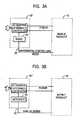
Figures 3A, 3B and 3C depict exemplary communication topologies to facilitate
communication between the charge controller 24 associated with the portable system 10 and the
adapter 32 of the present invention. In Figure 3A, the adapter 32' is modified to include a serial
communications interface 38 (e.g., RS232, RS434, Firewire, USB, etc.) to receive a serial
control signal 26' generated by the charge controller. In this embodiment, the feedback control
signal generated by the charge control is converted into serial communication data and
forwarded to the adapter 32'. In Figure 3B, the control signal 26" is an analog signal generated
by the error amplifiers, and accordingly, an appropriate analog interface (e.g., buffer) may be
provided in the adapter 32". Figure 3C does not utilize a separate control signal line, but rather,
modulates the feedback signal 26'" onto the power line. In this embodiment, both the adapter
32'" and system 10' are adapted with modulation/demodulation circuitry (42 and 44,
respectively) to generate a feedback signal 26'" that is transposed on the power line.
Thus, the present invention provides power management topologies that obviate the need
for power circuitry associated with a conventional battery charger circuit, and instead utilize the
power circuitry already present in an AC/DC adapter to generate regulated controllable power to
charge a battery and/or power a portable device. Advantageously, the costs of power switches
and power dissipation within the appliance have been eliminated. The cost of an additional
controller has been eliminated. Printed circuit board space has been saved within the appliance
as there is no need for bulky power switches. Additionally, optimum charge algorithms can be
implemented resulting in short battery charge times with full charge. Those skilled in the art will
recognize numerous modifications to the present invention. These and all other modifications as
may be apparent to one skilled in the art are deemed within the spirit and scope of the present
invention, only as limited by the appended claims.