EP1577977A1 - Electrical junction box - Google Patents
Electrical junction box Download PDFInfo
- Publication number
- EP1577977A1 EP1577977A1 EP05251642A EP05251642A EP1577977A1 EP 1577977 A1 EP1577977 A1 EP 1577977A1 EP 05251642 A EP05251642 A EP 05251642A EP 05251642 A EP05251642 A EP 05251642A EP 1577977 A1 EP1577977 A1 EP 1577977A1
- Authority
- EP
- European Patent Office
- Prior art keywords
- bus bars
- junction box
- tabs
- bus bar
- casing
- Prior art date
- Legal status (The legal status is an assumption and is not a legal conclusion. Google has not performed a legal analysis and makes no representation as to the accuracy of the status listed.)
- Granted
Links
Images


Classifications
-
- H—ELECTRICITY
- H01—ELECTRIC ELEMENTS
- H01R—ELECTRICALLY-CONDUCTIVE CONNECTIONS; STRUCTURAL ASSOCIATIONS OF A PLURALITY OF MUTUALLY-INSULATED ELECTRICAL CONNECTING ELEMENTS; COUPLING DEVICES; CURRENT COLLECTORS
- H01R9/00—Structural associations of a plurality of mutually-insulated electrical connecting elements, e.g. terminal strips or terminal blocks; Terminals or binding posts mounted upon a base or in a case; Bases therefor
- H01R9/22—Bases, e.g. strip, block, panel
- H01R9/24—Terminal blocks
- H01R9/2458—Electrical interconnections between terminal blocks
-
- B—PERFORMING OPERATIONS; TRANSPORTING
- B60—VEHICLES IN GENERAL
- B60R—VEHICLES, VEHICLE FITTINGS, OR VEHICLE PARTS, NOT OTHERWISE PROVIDED FOR
- B60R16/00—Electric or fluid circuits specially adapted for vehicles and not otherwise provided for; Arrangement of elements of electric or fluid circuits specially adapted for vehicles and not otherwise provided for
- B60R16/02—Electric or fluid circuits specially adapted for vehicles and not otherwise provided for; Arrangement of elements of electric or fluid circuits specially adapted for vehicles and not otherwise provided for electric constitutive elements
- B60R16/023—Electric or fluid circuits specially adapted for vehicles and not otherwise provided for; Arrangement of elements of electric or fluid circuits specially adapted for vehicles and not otherwise provided for electric constitutive elements for transmission of signals between vehicle parts or subsystems
- B60R16/0239—Electronic boxes
-
- H—ELECTRICITY
- H01—ELECTRIC ELEMENTS
- H01R—ELECTRICALLY-CONDUCTIVE CONNECTIONS; STRUCTURAL ASSOCIATIONS OF A PLURALITY OF MUTUALLY-INSULATED ELECTRICAL CONNECTING ELEMENTS; COUPLING DEVICES; CURRENT COLLECTORS
- H01R2201/00—Connectors or connections adapted for particular applications
- H01R2201/26—Connectors or connections adapted for particular applications for vehicles
Definitions
- This invention relates to an electrical junction box, especially for a vehicle, and more particularly relates to an electrical junction box containing bus bars which constitute an internal circuit which can form a splice circuit to a connector.
- the invention also relates to a vehicle having such an electrical junction box mounted in it.
- an electrical junction box to be mounted on a motor vehicle in Japanese Laid-Open Patent Application No. 2000-92660 and US Patent 6220875, and as shown in Figure 10 of the present application.
- This box has a casing having an upper casing member 2 and a lower casing member 3.
- a lamination body in which flat bus bars 5A to 5D are laminated with insulation plates 4A to 4D alternately is disposed in the casing. Punching out a conductive metal plate along a circuit pattern forms the flat bus bars 4A to 4D.
- the flat bus bars constitute an internal circuit. Bending given portions of the flat bus bars 5A to 5D forms tabs 5a.
- the tabs 5a project into connector receiving sockets 6, relay receiving sockets 7, and fuse containing portions 8 provided on the upper casing member 2 and lower casing member 3.
- the internal circuit is also composed of a material such as a single core wire, a single core wire to which an insulation displacement terminal is jointed, or a combination of a bus bar and a single core wire.
- the internal circuit is composed of a single core wire or a combination of the single core wire and a bus bar, the same problems occur.
- an object of the present invention is to provide an electrical junction box in which a splice circuit to a connector can be simply constructed and various branched connections can easily be formed, while making possible a small size of the box.
- the present invention provides an electrical junction box having:
- the internal circuit of this electrical junction box includes the lateral or flat bus bars and vertical bus bars. These bus bars are joined to one another by pressure contacts.
- the connector housing sockets can be disposed intensively (at high density) on the exterior of the casing on the arrangement area for the vertical bus bars.
- the tabs to be fitted to the connectors are mainly tabs of the vertical bus bars. Accordingly, it is possible to reduce the number of connector connection tabs provided on the flat bus bars, which are joined to the vertical bus bar.
- a circuit pattern of the flat bus bars can be simplified, flexibility in design of circuits can be enhanced, and the number of lamination layers of the flat bus bars can be decreased.
- the vertical bus bars can be connected to the connectors at a high density.
- an electrical junction box at least one of said second bus bars has a plurality of said tabs, spaced apart along the second bus bar and located at the upper side and/or the lower side thereof, which tabs extend respectively into different ones of said connector housing sockets, whereby a direct connection is made via the second bus bar between at least two of said external electrical connectors, in use.
- the tabs coupled to the terminals in one or more of the connectors form a splice connection through the vertical bus bar.
- the terminals in a single connector fitted in this socket can be spliced. Also, if the tabs pass through the terminal holes in different connector housing sockets juxtaposed in the longitudinal direction of the vertical bus bar, it is possible to form a splice circuit between different connectors.
- the present invention can reduce the number of parts significantly and enhance flexibility in design of circuit patterns of flat bus bars.
- the tabs provided on the vertical bus bar may however be bent at an angle of 90 degrees to pass through the terminal holes in the base wall of the connector housing socket.
- a long side direction of the rectangular connector housing socket then accords with a long side direction (width direction) of the tabs.
- the long side direction of the connector housing sockets juxtaposed and in the longitudinal direction of the vertical bus bars is perpendicular to the long side direction of the tabs.
- the long side direction of terminal holes in a typical connector housing socket is positioned parallel to a long side direction of the connector housing socket while a long side direction of a connector joined to an end of an electrical cable and fitted in a connector housing socket accords with a long side direction of terminals in the connector. Consequently, the direction of the tab of the vertical bus bar is positioned perpendicular to the direction of the terminal of the connector to be fitted to the tab and the terminal cannot be fitted in a typical connector used conventionally. Accordingly, in the present invention, the tabs of the vertical bus bar may be bent at an angle of 90 degrees to be fitted in the typical conventional connector, thereby eliminating the need of a redesigned connector.
- the flat first bus bars and insulation layers may be laminated on one another alternately.
- An end of the each flat bus bar may be bent to form each of the forked terminal portion thereof, which connects to the vertical bus bar.
- the forked terminals may be covered with a protective insulation block.
- the block is provided with terminal containing-chambers for receiving the respective forked terminals and with terminal holes for insertion of terminal portions of the vertical bus bars.
- the terminal holes communicate with the terminal containing-chambers.
- the protective insulation block may be fixed on one of the insulation layers.
- the protective insulation block covers the forked terminals of the flat bus bars, it is possible to prevent these terminals from being broken by external interference before they are coupled to the vertical bus bar. Also, since the vertical bus bar terminals are inserted into the terminal holes communicated with the terminal containing-chambers of the block to bring the vertical bus bars into press contact with the forked terminals, the forked terminals and vertical bus bars are smoothly brought into pressure contact with each other together, thereby preventing deformation and breakage of the respective terminals.
- the forked terminals of the flat bus bars on different layers of the stacked assembly of the bus bars may be brought into pressure contact with a single vertical bus bar, so that the flat bus bars are joined to each other through the single vertical bus bar.
- the vertical bus bar can carry out a connection between layers of the flat bus bars, it is not necessary to use transfer terminals in order to carry out a connection between different layers of the flat bus bars. It is therefore possible to reduce the number of parts and to eliminate an assembling step, and it is also possible to enhance flexibility in design of circuits of the flat bus bars, thereby forming a circuit pattern efficiently and allowing reduction of the number of laminations of the flat bus bars.
- a plurality of forked terminals may be provided on one of the flat bus bars, and these terminals are brought into press contact with a plurality of the vertical bus bars.
- the vertical bus bars are joined to one another through the flat bus bar.
- Tabs may extend from the flat bus bars and pass through terminal holes in connector housing sockets, in fuse containing portions and relay containing portions on the first region for flat bus bars on the upper casing member and/or the lower casing member, to achieve connection to fuses, relays and connectors.
- the connector housing sockets can be disposed intensively on the second region for the vertical bus bars, there can be achieved a tolerance in positioning the fuse containing portions and relay containing portions in view of a relationship between the positions of the tabs of the flat bus bars. This can enhance flexibility in design of circuits of the flat bus bars.
- the vertical bus bars and flat bus bars constitute the internal circuit and many juxtaposed vertical bus bars can be brought into pressure contact with the flat bus bars, the vertical bus bars coupled to the connectors can be easily joined to the flat bus bars coupled to fuses or relays to form circuits.
- a plurality of tabs extend from the vertical bus bar in the longitudinal direction of the bus bar and these tabs are joined to the terminals of the connector.
- the orientation words “upper”, “lower”, “upwards”, “downwards”, “vertical”, “laterally”, “sideways” etc. are used for convenience of description of the electrical junction box. In actual use, the box may be arranged in any suitable direction.
- FIGS 1 to 5 show a first embodiment of an electrical junction box in accordance with the present invention.
- the electrical junction box 10 has a casing including an upper casing member 11 and a lower casing member 12, both formed of molded plastics material.
- An internal circuit is accommodated in the casing.
- the internal circuit includes vertical bus bars 20, a lamination body 32 in which flat bus bars 30 and insulation plates 31 are laminated alternately, and a printed circuit board 40.
- the vertical bus bars 20 are so called because they each have a main base portion 23 which lies in a plane which extends upwardly and downwardly (vertically) relative to the upper and lower casing members 11, 12.
- the flat bus bars 30 are so called because they each have a main portion which lies in a plane which extends laterally or sideways (i.e. flat) relative to the upper and lower casing members 11, 12.
- the electrical junction box 10 is divided laterally into a first half side which is an arrangement area S1 for the vertical bus bars 20 (the area enclosed by an alternate long and short dash line in Figures 3A and 3B) in which a plurality of the vertical bus bars 20 are juxtaposed and a second half side which is an arrangement area S2 for flat bus bars (an area enclosed by an alternate long and short two-dashes line in Figures 3A and 3B) in which the lamination body 32 including the flat bus bars 30 and insulation plates 31 are disposed.
- a plurality of parallel juxtaposed vertical bus bar containing-chambers 13 are provided in the arrangement area S1 for the vertical bus bars 20 in the lower casing member 12.
- the chambers 13 extend from the boundary between the arrangement area S1 and the arrangement area S2 to the other side of the arrangement area S1.
- a main base portion 23 of each vertical bus bar 20 is pushed into and thereby secured in the respective chamber 13.
- the numerous vertical bus bars 20 are pushed into the chambers 13 with their first ends being aligned at the side of the arrangement area S2. Their second ends are at the opposite side of the area S1.
- a bus bar connection tab 21 extends upward and makes a press contact with a tuning fork terminal 33 of at least one of the flat bus bars 30.
- a press contact here means a pressure contact in which electrical contact is maintained by pressure exerted by the contacting components.
- each flat bus bar 30 is positioned in the arrangement area S2 and an end portion of the flat bus bar 30 is disposed at the boundary between the arrangement area S2 and the arrangement area S1.
- the tuning fork terminal 33 is bent downward from an end of the flat bus bar 30 to engage the bus bar connection tab 21 of the vertical bus bar 20.
- the terminal 33 is disposed perpendicularly to the connection tab 21 of the vertical bus bar 20.
- the tuning fork terminals 33 of the flat bus bars 30 are staggered laterally in the arrangement area S2 so that the vertical bus bars 20 can be arranged at a narrow pitch, i.e. close together.
- the tuning fork terminals 33 of the flat bus bars 30 are previously covered with a protection resin block 50 to protect them, before they are brought into press contact with the connection tabs 21 of the vertical bus bars 20.
- the protection resin block 50 is provided with chambers 51 containing the terminals 33 and staggered in the same manner as the terminals 33.
- the connection tabs 21 of the vertical bus bars 20 are inserted into the chambers 51 through terminal holes 52 formed in the bottom walls of the chambers 51.
- the protection resin block 50 is fixed on the lower side of the lowermost insulation plate 31 (see Figure 1) and the tuning fork terminals 33 of the flat bus bars 30 are pushed downwards into the chambers 51.
- each vertical bus bar 20 is disposed vertically in the electrical junction box.
- a plurality of tabs 22 extend upward or downward from one or both of the upper and lower edges of the base portion 23 and are spaced away from one another at their respective positions on the base portion 23.
- the tabs 22 extending upward from the base portions 23 project into the connector housing sockets 14 of the upper casing member 11 while the tabs extending downward from the base portion 23 project into the connector housing sockets 15 in the lower casing member 12.
- the tabs 22 extending from the upper and lower edges of the base portion 23 of the vertical bus bar 20 are not bent with respect to the base portion 23 (i.e. they lie in the same plane as the base portion 23), so that the width direction of the tab 22 accords with the longitudinal direction of the vertical bus bar 20.
- the tabs 22 project into plural connector housing sockets 14 and 15 (indicated by 14A, 14B and 15A, 15B, and 15C in Figure 3), which are juxtaposed in the longitudinal direction of the vertical bus bars 20.
- the connector housing sockets 14 and 15 have rectangular configurations, as seen in Figure 3.
- the long side direction of each of the connector housing sockets 14 and 15 is perpendicular to the width direction of each tab 22.
- the tabs 22 extending from the same vertical bus bar 20 thus can project into the juxtaposed connector housing sockets 14A, 14B and 15A to 15C.
- the long side direction of each of slot-shaped terminal holes 14b and 15b formed in bottom walls 14a and 15a of the connector housing sockets 14 and 15 is perpendicular to the long side direction of each of the connector housing sockets 14 and 15 in correspondence with the direction of each of the tabs 22 that pass through the terminal holes 14b and 15b.
- the terminal holes 14b and 15b are staggered in the sockets 14A, 14B, so that the mating terminals of the connectors to be coupled to the tabs 22 may be arranged at a small pitch (close spacing.
- terminal containing-chambers 61 are provided by a staggered manner in rows in the connector 60 which is to be fitted into the connector housing socket 14.
- the terminal containing-chambers 61 houses electrical terminals (not shown) which engage the tabs 22 that project into the corresponding connector housing socket 14.
- the terminals of the connector 60 are of a conventional type, formed by bending sheet metal, and have slots to engage the tabs 22 in a conventional manner. These terminals are joined to wires of for example a wiring harness of a motor vehicle.
- the terminal in the chamber 61 in the connector 60 is positioned with its slot in a direction corresponding to that of the tab 22 which projects into the socket 14 in the upper casing member 11.
- the width direction of the tab 22 is perpendicular to the long side direction of the rectangular connector housing socket 14.
- the tab 22 extends from the base portion 23 of the vertical bus bar 20 as it is and is not bent at an angle of 90 degrees.
- the slot direction of the mating terminal in the chamber 61 of the connector 60 is also perpendicular to a long side direction of the connector housing socket 14.
- each bus bar 20 The plurality of tabs 22 of each bus bar 20 are spaced away from one another and extend into a plurality of the juxtaposed connector containing-sections 14A and 14B (15A, 15B, 15C) in the arrangement area S1. Accordingly, the connectors 60 may be spliced (electrically connected) through the vertical bus bars 20 in a simple manner.
- terminal portions 34 are formed on each flat bus bar 30 by bending the given portions of the bus bar 30 upward or downward.
- the terminal portions 34 project for example into a relay housing socket 16 or a fuse housing socket 17 in the upper casing member 11, or they project for example into a connector housing socket 17 or a fuse housing socket 18 in the lower casing member 12 (see Figures 3A and 3B).
- a printed board containing-section 19 is formed by a raised upper wall portion of the upper casing member 11, at a given position of the upper casing member 11.
- a printed board 40 (pcb) is accommodated in this section 19 with an insulation plate 41 interposed in the casing between the lamination body 32 and the printed board 40.
- Elongate conductor connection tabs 35 extend upward from at least one of the flat bus bars 30.
- the conductor connection tabs 35 pass through a raised connection tab support section 42 of the insulation plate 41 and the tabs 35 are connected to conductors of the printed board 40 disposed above in the section 19 by means of soldering.
- the printed board 40 is supported at a given height in the section 19 by means of soldering the printed board 40 to board securing-tabs 36 that extend from the flat bus bar 30 and pass through raised securing tab supports 43.
- the internal circuit includes the vertical bus bars 20 and flat bus bars 30
- the external connectors 60 can be disposed intensively on the arrangement area S1 to be connected to the tabs 22 of the vertical bus bars 20
- a circuit pattern of the flat bus bars 30 is simplified and flexibility in design of circuits is enhanced. Accordingly, it is possible to reduce the number of lamination layers of the lamination body 32 including the flat bus bars 30 and insulation plates 31, thereby lowering cost of production and reducing the size of the electrical junction box 10.
- the protection resin block 50 covers the tuning fork terminals 33 of the flat bus bars 30, it is possible to prevent the tuning fork terminals 33 from being broken by external interference before the terminals 33 are coupled to the vertical bus bars 20. Also, since the bus bar connection tabs 21 coupled to the tuning fork terminals 33 are constrained at the regular insertion positions by the terminal holes 52 in the protection resin block 50, it is possible to prevent the bus bar connection tabs 21 and tuning fork terminals 33 from being deflected excessively by a pushing force exerted upon press contact between the tuning fork terminals 33 and the bus bar connection tabs 21. This permits size reduction of the tab 21, increasing the contact pressure.
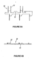
- Figures 6A, 6B and 7 show a second embodiment of the present invention, which differs from the first embodiment in that tabs extend from vertical bus bars in a direction different from that in the first embodiment.
- the tabs 22' extending from the base portion 23' of the vertical bus bar 20' are bent at an angle of 90 degrees near the edge of the base portion 23' so that the width direction of the tab 22' accords with the long side direction of a connector housing socket 14'.
- FIGS 8 and 9 show a third embodiment of the present invention, in which a vertical bus bar 20" is used as a transfer bus bar for intermediate layer connection of flat bus bars. Also a flat bus bar 30" is used as a transfer bus bar for coupling the vertical bus bars 20" to each other. These features may be added to the construction of the first embodiment.
- FIG 8 shows that tuning fork terminals 34A" and 33B" formed by bending flat bus bars 30A" and 30B" of different layers are disposed at the opposed positions in a lateral direction. These opposed tuning fork terminals 34A” and 33B" are brought into press contact with bus bar connection tab 21" of the same vertical bus bar 20". Thus, the flat bus bars 33A" and 33B" of the different layers are connected through the vertical bus bar 20".
- tuning fork terminals 33C extend from a base portion of one flat bus bar 30C".
- the tuning fork terminals 33C" are brought into press contact with the bus bar connection tabs 21" of several of the vertical bus bars 20".
- the different vertical bus bars 20" are coupled to one another through the single flat bus bar 30C".
- the flat bus bar 30C" is provided with only the tuning fork terminals 33C" in this third embodiment, a terminal portion to be coupled to a terminal of a connector or other component may be provided additionally on the flat bus bar 30C".
Landscapes
- Engineering & Computer Science (AREA)
- Mechanical Engineering (AREA)
- Connection Or Junction Boxes (AREA)
Abstract
Description
- This invention relates to an electrical junction box, especially for a vehicle, and more particularly relates to an electrical junction box containing bus bars which constitute an internal circuit which can form a splice circuit to a connector. The invention also relates to a vehicle having such an electrical junction box mounted in it.
- Heretofore, the present applicants have proposed an electrical junction box to be mounted on a motor vehicle in Japanese Laid-Open Patent Application No. 2000-92660 and US Patent 6220875, and as shown in Figure 10 of the present application. This box has a casing having an
upper casing member 2 and alower casing member 3. A lamination body in whichflat bus bars 5A to 5D are laminated withinsulation plates 4A to 4D alternately is disposed in the casing. Punching out a conductive metal plate along a circuit pattern forms theflat bus bars 4A to 4D. The flat bus bars constitute an internal circuit. Bending given portions of theflat bus bars 5A to 5D formstabs 5a. Thetabs 5a project intoconnector receiving sockets 6, relay receiving sockets 7, andfuse containing portions 8 provided on theupper casing member 2 andlower casing member 3. - The internal circuit is also composed of a material such as a single core wire, a single core wire to which an insulation displacement terminal is jointed, or a combination of a bus bar and a single core wire.
- However, in the case of the
electrical junction box 1 of Figure 10, or in the case where terminals in connectors to be received in the differentconnector receiving sockets 6 must be spliced to one another, or particularly in the case where terminals of the bus bars on different layers must be spliced to one another, an internal circuit is complicated and efficiency in arrangement of circuits is low. Consequently, there are problems that the number of lamination layers of the bus bars is increased, cost in production is increased, and the electrical junction box is of large size. - In the case where the internal circuit is composed of a single core wire or a combination of the single core wire and a bus bar, the same problems occur.
- In view of the above problems, an object of the present invention is to provide an electrical junction box in which a splice circuit to a connector can be simply constructed and various branched connections can easily be formed, while making possible a small size of the box.
- The present invention provides an electrical junction box having:
- a casing comprising upper and lower casing members coupled together, said casing having a plurality of connector housing sockets which, in use, receive external electrical connectors,
- a plurality of first bus bars each having a main portion which extends in a lateral plane relative to said casing, said first bus bars being arranged in a first region of said casing,
- a plurality of second bus bars each having a main portion which extends in a vertical plane relative to said casing, said second bus bars being arranged in a plurality of juxtaposed compartments of said casing in a second region of said casing which is located alongside and laterally with respect to said first region, said first and second bus bars having interconnecting terminal portions by which respective first bus bars make electrical connections with respective second bus bars at the zone where said first and second regions join, each said electrical connection between the first and second bus bars comprising a forked terminal portion of one bus bar and a projecting terminal portion of the other bus bar, the forked terminal portion making pressure contact with the projecting terminal portion,
-
- The internal circuit of this electrical junction box includes the lateral or flat bus bars and vertical bus bars. These bus bars are joined to one another by pressure contacts. The connector housing sockets can be disposed intensively (at high density) on the exterior of the casing on the arrangement area for the vertical bus bars. The tabs to be fitted to the connectors are mainly tabs of the vertical bus bars. Accordingly, it is possible to reduce the number of connector connection tabs provided on the flat bus bars, which are joined to the vertical bus bar. Thus, a circuit pattern of the flat bus bars can be simplified, flexibility in design of circuits can be enhanced, and the number of lamination layers of the flat bus bars can be decreased.
- Also, since the tabs can extend from opposite sides at the same positions on the vertical bus bars, the vertical bus bars can be connected to the connectors at a high density.
- Preferably an electrical junction box at least one of said second bus bars has a plurality of said tabs, spaced apart along the second bus bar and located at the upper side and/or the lower side thereof, which tabs extend respectively into different ones of said connector housing sockets, whereby a direct connection is made via the second bus bar between at least two of said external electrical connectors, in use. In this way the tabs coupled to the terminals in one or more of the connectors form a splice connection through the vertical bus bar.
- Thus, in the case where a plurality of tabs extending from single vertical bus bar pass through a plurality of terminal holes in a single connector housing socket, the terminals in a single connector fitted in this socket can be spliced. Also, if the tabs pass through the terminal holes in different connector housing sockets juxtaposed in the longitudinal direction of the vertical bus bar, it is possible to form a splice circuit between different connectors.
- Thus, since the plural tabs extending from the vertical bus bar are coupled to the connector or connectors, it is possible to make a splice connection simply. In comparison with a conventional internal circuit that has used only flat bus bars, the present invention can reduce the number of parts significantly and enhance flexibility in design of circuit patterns of flat bus bars.
- The tabs provided on the vertical bus bar may however be bent at an angle of 90 degrees to pass through the terminal holes in the base wall of the connector housing socket. A long side direction of the rectangular connector housing socket then accords with a long side direction (width direction) of the tabs.
- Thus, the long side direction of the connector housing sockets juxtaposed and in the longitudinal direction of the vertical bus bars is perpendicular to the long side direction of the tabs. Generally, the long side direction of terminal holes in a typical connector housing socket is positioned parallel to a long side direction of the connector housing socket while a long side direction of a connector joined to an end of an electrical cable and fitted in a connector housing socket accords with a long side direction of terminals in the connector. Consequently, the direction of the tab of the vertical bus bar is positioned perpendicular to the direction of the terminal of the connector to be fitted to the tab and the terminal cannot be fitted in a typical connector used conventionally. Accordingly, in the present invention, the tabs of the vertical bus bar may be bent at an angle of 90 degrees to be fitted in the typical conventional connector, thereby eliminating the need of a redesigned connector.
- The flat first bus bars and insulation layers may be laminated on one another alternately. An end of the each flat bus bar may be bent to form each of the forked terminal portion thereof, which connects to the vertical bus bar. The forked terminals may be covered with a protective insulation block. The block is provided with terminal containing-chambers for receiving the respective forked terminals and with terminal holes for insertion of terminal portions of the vertical bus bars. The terminal holes communicate with the terminal containing-chambers. The protective insulation block may be fixed on one of the insulation layers.
- With this construction, since the protective insulation block covers the forked terminals of the flat bus bars, it is possible to prevent these terminals from being broken by external interference before they are coupled to the vertical bus bar. Also, since the vertical bus bar terminals are inserted into the terminal holes communicated with the terminal containing-chambers of the block to bring the vertical bus bars into press contact with the forked terminals, the forked terminals and vertical bus bars are smoothly brought into pressure contact with each other together, thereby preventing deformation and breakage of the respective terminals.
- The forked terminals of the flat bus bars on different layers of the stacked assembly of the bus bars may be brought into pressure contact with a single vertical bus bar, so that the flat bus bars are joined to each other through the single vertical bus bar. With this construction, since the vertical bus bar can carry out a connection between layers of the flat bus bars, it is not necessary to use transfer terminals in order to carry out a connection between different layers of the flat bus bars. It is therefore possible to reduce the number of parts and to eliminate an assembling step, and it is also possible to enhance flexibility in design of circuits of the flat bus bars, thereby forming a circuit pattern efficiently and allowing reduction of the number of laminations of the flat bus bars.
- A plurality of forked terminals may be provided on one of the flat bus bars, and these terminals are brought into press contact with a plurality of the vertical bus bars. The vertical bus bars are joined to one another through the flat bus bar. Thus, it is possible to utilize the flat bus bar for joining of the vertical bus bars and thus to obtain various splice connections between the connectors through the vertical bus bars.
- Tabs may extend from the flat bus bars and pass through terminal holes in connector housing sockets, in fuse containing portions and relay containing portions on the first region for flat bus bars on the upper casing member and/or the lower casing member, to achieve connection to fuses, relays and connectors. In the invention, since the connector housing sockets can be disposed intensively on the second region for the vertical bus bars, there can be achieved a tolerance in positioning the fuse containing portions and relay containing portions in view of a relationship between the positions of the tabs of the flat bus bars. This can enhance flexibility in design of circuits of the flat bus bars.
- It will be apparent from the foregoing that according to the present invention, since the vertical bus bars and flat bus bars constitute the internal circuit and many juxtaposed vertical bus bars can be brought into pressure contact with the flat bus bars, the vertical bus bars coupled to the connectors can be easily joined to the flat bus bars coupled to fuses or relays to form circuits.
- Furthermore, since the tabs extending from the upper edge and/or the lower edge of the vertical bus bars are joined to the connectors, it is possible to intensively dispose the connector housing sockets on the second region for vertical bus bars. Thus, since it is not necessary to provide many tabs for connection to connectors on the flat bus bar, a circuit pattern of the flat bus bars will be simplified and thus the number of laminations of the flat bus bars will be reduced.
- In particular, a plurality of tabs extend from the vertical bus bar in the longitudinal direction of the bus bar and these tabs are joined to the terminals of the connector. Thus, it is possible simply to form a splice circuit through the vertical bus bar in the same connector or between different connectors.
- In this specification, the orientation words "upper", "lower", "upwards", "downwards", "vertical", "laterally", "sideways" etc. are used for convenience of description of the electrical junction box. In actual use, the box may be arranged in any suitable direction.
- Embodiments of the present invention will be described below by way of non-limitative example, referring to the drawings. In the drawings: -
- Figure 1 is an exploded perspective view of a first embodiment of an electrical junction box in accordance with the present invention.
- Figure 2 is a sectional view of the electrical junction box of Figure 1, in a vertical plane.
- Figure 3A is a plan view of the electrical junction box of Figure 1, and Figure 3B is a bottom view of the electrical junction box of Figure 1.
- Figures 4A and 4B are a plan view and a sectional view of a protection resin block of the box of Figure 1, illustrating tuning fork terminals of a flat bus bar and bus bar connection tabs of a vertical bus bar pressed into and secured in the protection resin block.
- Figure 5 is a plan view of a connector to be fitted in a connector housing socket of the box of Figure 1.
- Figure 6A is a front elevation view of a vertical bus bar used in a second embodiment of the electrical junction box in accordance with the present invention, and Figure 6B is a plan view of this vertical bus bar.
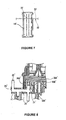
- Figure 7 is an explanatory view, illustrating a relationship between tabs of the vertical bus bar and a connector housing socket.
- Figure 8 is a sectional view of a part of a third embodiment of an electrical junction box in accordance with the present invention, illustrating that laminated flat bus bars are jointed to each other through the vertical bus bars.
- Figure 9 is a plan view of a flat bus bar used for coupling vertical bus bars to one another in an embodiment of this invention.
- Figure 10 is an exploded perspective view of a known electrical junction box described above.
-
- Figures 1 to 5 show a first embodiment of an electrical junction box in accordance with the present invention. The
electrical junction box 10 has a casing including anupper casing member 11 and alower casing member 12, both formed of molded plastics material. An internal circuit is accommodated in the casing. The internal circuit includes vertical bus bars 20, alamination body 32 in which flat bus bars 30 andinsulation plates 31 are laminated alternately, and a printedcircuit board 40. The vertical bus bars 20 are so called because they each have amain base portion 23 which lies in a plane which extends upwardly and downwardly (vertically) relative to the upper andlower casing members lower casing members - The
electrical junction box 10 is divided laterally into a first half side which is an arrangement area S1 for the vertical bus bars 20 (the area enclosed by an alternate long and short dash line in Figures 3A and 3B) in which a plurality of the vertical bus bars 20 are juxtaposed and a second half side which is an arrangement area S2 for flat bus bars (an area enclosed by an alternate long and short two-dashes line in Figures 3A and 3B) in which thelamination body 32 including the flat bus bars 30 andinsulation plates 31 are disposed. - As shown in Figures 1 and 2, a plurality of parallel juxtaposed vertical bus bar containing-
chambers 13 are provided in the arrangement area S1 for the vertical bus bars 20 in thelower casing member 12. Thechambers 13 extend from the boundary between the arrangement area S1 and the arrangement area S2 to the other side of the arrangement area S1. Amain base portion 23 of eachvertical bus bar 20 is pushed into and thereby secured in therespective chamber 13. - The numerous vertical bus bars 20 are pushed into the
chambers 13 with their first ends being aligned at the side of the arrangement area S2. Their second ends are at the opposite side of the area S1. As shown in Figure 2, at the first end of each bar 20 a busbar connection tab 21 extends upward and makes a press contact with atuning fork terminal 33 of at least one of the flat bus bars 30. A press contact here means a pressure contact in which electrical contact is maintained by pressure exerted by the contacting components. - On the other hand, each
flat bus bar 30 is positioned in the arrangement area S2 and an end portion of theflat bus bar 30 is disposed at the boundary between the arrangement area S2 and the arrangement area S1. Thetuning fork terminal 33 is bent downward from an end of theflat bus bar 30 to engage the busbar connection tab 21 of thevertical bus bar 20. The terminal 33 is disposed perpendicularly to theconnection tab 21 of thevertical bus bar 20. When thelamination body 32 is accommodated in thelower casing member 12, a givenconnection tab 21 is inserted into and secured in the slit in the terminal 33, as shown in Figure 2. - The
tuning fork terminals 33 of the flat bus bars 30 are staggered laterally in the arrangement area S2 so that the vertical bus bars 20 can be arranged at a narrow pitch, i.e. close together. - The
tuning fork terminals 33 of the flat bus bars 30 are previously covered with aprotection resin block 50 to protect them, before they are brought into press contact with theconnection tabs 21 of the vertical bus bars 20. As shown in Figure 4A, theprotection resin block 50 is provided withchambers 51 containing theterminals 33 and staggered in the same manner as theterminals 33. Theconnection tabs 21 of the vertical bus bars 20 are inserted into thechambers 51 throughterminal holes 52 formed in the bottom walls of thechambers 51. Theprotection resin block 50 is fixed on the lower side of the lowermost insulation plate 31 (see Figure 1) and thetuning fork terminals 33 of the flat bus bars 30 are pushed downwards into thechambers 51. - The
base portion 23 of eachvertical bus bar 20 is disposed vertically in the electrical junction box. A plurality oftabs 22 extend upward or downward from one or both of the upper and lower edges of thebase portion 23 and are spaced away from one another at their respective positions on thebase portion 23. Thetabs 22 extending upward from thebase portions 23 project into theconnector housing sockets 14 of theupper casing member 11 while the tabs extending downward from thebase portion 23 project into theconnector housing sockets 15 in thelower casing member 12. - The
tabs 22 extending from the upper and lower edges of thebase portion 23 of thevertical bus bar 20 are not bent with respect to the base portion 23 (i.e. they lie in the same plane as the base portion 23), so that the width direction of thetab 22 accords with the longitudinal direction of thevertical bus bar 20. - The
tabs 22 project into pluralconnector housing sockets 14 and 15 (indicated by 14A, 14B and 15A, 15B, and 15C in Figure 3), which are juxtaposed in the longitudinal direction of the vertical bus bars 20. Theconnector housing sockets connector housing sockets tab 22. - The
tabs 22 extending from the samevertical bus bar 20 thus can project into the juxtaposedconnector housing sockets terminal holes bottom walls connector housing sockets connector housing sockets tabs 22 that pass through theterminal holes sockets tabs 22 may be arranged at a small pitch (close spacing. - As shown in Figure 5, terminal containing-
chambers 61 are provided by a staggered manner in rows in theconnector 60 which is to be fitted into theconnector housing socket 14. The terminal containing-chambers 61 houses electrical terminals (not shown) which engage thetabs 22 that project into the correspondingconnector housing socket 14. - The terminals of the
connector 60 are of a conventional type, formed by bending sheet metal, and have slots to engage thetabs 22 in a conventional manner. These terminals are joined to wires of for example a wiring harness of a motor vehicle. The terminal in thechamber 61 in theconnector 60 is positioned with its slot in a direction corresponding to that of thetab 22 which projects into thesocket 14 in theupper casing member 11. - Thus, as mentioned, the width direction of the
tab 22 is perpendicular to the long side direction of the rectangularconnector housing socket 14. However, thetab 22 extends from thebase portion 23 of thevertical bus bar 20 as it is and is not bent at an angle of 90 degrees. The slot direction of the mating terminal in thechamber 61 of theconnector 60 is also perpendicular to a long side direction of theconnector housing socket 14. - Since the
connector housing sockets 15 provided in the arrangement area S1 in thelower casing member 12 have the same structure as those in theupper casing member 11, their detailed explanation will be omitted here. - The plurality of
tabs 22 of eachbus bar 20 are spaced away from one another and extend into a plurality of the juxtaposed connector containing-sections connectors 60 may be spliced (electrically connected) through the vertical bus bars 20 in a simple manner. - On the other hand,
terminal portions 34 are formed on eachflat bus bar 30 by bending the given portions of thebus bar 30 upward or downward. Theterminal portions 34 project for example into arelay housing socket 16 or afuse housing socket 17 in theupper casing member 11, or they project for example into aconnector housing socket 17 or afuse housing socket 18 in the lower casing member 12 (see Figures 3A and 3B). - As shown in Figure 2, a printed board containing-
section 19 is formed by a raised upper wall portion of theupper casing member 11, at a given position of theupper casing member 11. A printed board 40 (pcb) is accommodated in thissection 19 with aninsulation plate 41 interposed in the casing between thelamination body 32 and the printedboard 40. Elongateconductor connection tabs 35 extend upward from at least one of the flat bus bars 30. Theconductor connection tabs 35 pass through a raised connectiontab support section 42 of theinsulation plate 41 and thetabs 35 are connected to conductors of the printedboard 40 disposed above in thesection 19 by means of soldering. The printedboard 40 is supported at a given height in thesection 19 by means of soldering the printedboard 40 to board securing-tabs 36 that extend from theflat bus bar 30 and pass through raised securing tab supports 43. - In the above-described construction, since the interior of the casing is divided into the arrangement area S1 for vertical bus bars and the arrangement area S2 for flat bus bars, and the internal circuit includes the vertical bus bars 20 and flat bus bars 30, there are achieved advantages that the
external connectors 60 can be disposed intensively on the arrangement area S1 to be connected to thetabs 22 of the vertical bus bars 20, a circuit pattern of the flat bus bars 30 is simplified and flexibility in design of circuits is enhanced. Accordingly, it is possible to reduce the number of lamination layers of thelamination body 32 including the flat bus bars 30 andinsulation plates 31, thereby lowering cost of production and reducing the size of theelectrical junction box 10. - Since the
protection resin block 50 covers thetuning fork terminals 33 of the flat bus bars 30, it is possible to prevent thetuning fork terminals 33 from being broken by external interference before theterminals 33 are coupled to the vertical bus bars 20. Also, since the busbar connection tabs 21 coupled to thetuning fork terminals 33 are constrained at the regular insertion positions by the terminal holes 52 in theprotection resin block 50, it is possible to prevent the busbar connection tabs 21 andtuning fork terminals 33 from being deflected excessively by a pushing force exerted upon press contact between thetuning fork terminals 33 and the busbar connection tabs 21. This permits size reduction of thetab 21, increasing the contact pressure. - Figures 6A, 6B and 7 show a second embodiment of the present invention, which differs from the first embodiment in that tabs extend from vertical bus bars in a direction different from that in the first embodiment. The tabs 22' extending from the base portion 23' of the vertical bus bar 20' are bent at an angle of 90 degrees near the edge of the base portion 23' so that the width direction of the tab 22' accords with the long side direction of a connector housing socket 14'.
- With the construction of Figures 6A, 6B and 7, it is possible to couple the tabs 22' of the vertical bus bars 20' to the terminals in an external conventional connector whose long side direction accords with the length direction of a terminal slot.
- Since the other structures and operational effects in the second embodiment are the same as those in the first embodiment, their explanation will be omitted.
- Figures 8 and 9 show a third embodiment of the present invention, in which a
vertical bus bar 20" is used as a transfer bus bar for intermediate layer connection of flat bus bars. Also aflat bus bar 30" is used as a transfer bus bar for coupling the vertical bus bars 20" to each other. These features may be added to the construction of the first embodiment. - Figure 8 shows that
tuning fork terminals 34A" and 33B" formed by bendingflat bus bars 30A" and 30B" of different layers are disposed at the opposed positions in a lateral direction. These opposedtuning fork terminals 34A" and 33B" are brought into press contact with busbar connection tab 21" of the samevertical bus bar 20". Thus, the flat bus bars 33A" and 33B" of the different layers are connected through thevertical bus bar 20". - Also, as shown in Figure 9, only the
tuning fork terminals 33C" extend from a base portion of oneflat bus bar 30C". Thetuning fork terminals 33C" are brought into press contact with the busbar connection tabs 21" of several of the vertical bus bars 20". Thus, the different vertical bus bars 20" are coupled to one another through the singleflat bus bar 30C". - Although the
flat bus bar 30C" is provided with only thetuning fork terminals 33C" in this third embodiment, a terminal portion to be coupled to a terminal of a connector or other component may be provided additionally on theflat bus bar 30C". - With the constructions of Figures 8 and 9, it is possible to efficiently arrange the bus bars by using either the
vertical bus bar 20" or theflat bus bar 30" as a transfer bus bar and by connecting the other bus bars to each other between the layers. - Since the other structures and operational effects in the second embodiment are the same as those in the first embodiment, their explanation will be omitted. The same reference numerals are used for corresponding elements in the several embodiments.
said second bus bars having tabs which project into said connector housing sockets in order to make electrical connection to terminals of said external electrical connectors, in use.
Claims (9)
- An electrical junction box (10) having:said first and second bus bars (20, 30) having interconnecting terminal portions (21, 33) by which respective first bus bars make electrical connections with respective second bus bars at the zone where said first and second regions join, each said electrical connection between the first and second bus bars comprising a forked terminal portion (33) of one bus bar and a projecting terminal portion (21) of the other bus bar, the forked terminal portion (33) making pressure contact with the projecting terminal portion (21),a casing comprising upper and lower casing members (11, 12) coupled together, said casing having a plurality of connector housing sockets (14, 15) which, in use, receive external electrical connectors,a plurality of first bus bars (30) each having a main portion which extends in a lateral plane relative to said casing, said first bus bars (30) being arranged in a first region (52) of said casing,a plurality of second bus bars (20) each having a main portion (23) which extends in a vertical plane relative to said casing, said second bus bars (20) being arranged in a plurality of juxtaposed compartments (13) of said casing in a second region (51) of said casing which is located alongside and laterally with respect to said first region (52),
said second bus bars (20) having tabs (22) which project into said connector housing sockets (14, 15) in order to make electrical connection to terminals of said external electrical connectors, in use. - An electrical junction box according to claim 1, wherein at least one of said second bus bars (20) has a plurality of said tabs (22), spaced apart along the second bus bar and located at the upper side and/or the lower side thereof, which tabs (22) extend respectively into different ones of said connector housing sockets (14, 15), whereby a direct connection is made via the second bus bar between at least two of said external electrical connectors, in use.
- An electrical junction box according to claim 1 or 2, wherein said tabs (22') of said second bus bars (20') are bent through 90°, relative to said main portions of said second bus bars, to project into said connector housing sockets (14, 15), said connector housing sockets (14, 15) being elongate and having their elongate direction aligned with the width direction of said tabs (22') of said second bus bars (20') which are bent through 90°.
- An electrical junction box according to any one of claims 1 to 3, wherein in said first region (52) said first bus bars (30) are stacked one above another with insulation layers (31) interposed between them, and end portions of said first bus bars (30) are bent to form said terminal portions (33) of said electrical connections.
- An electrical junction box according to claim 4, wherein said terminal portions (33) of a plurality of said first bus bars (30), stacked one above another, make electrical connections to the same one of said second bus bars (20) whereby said first bus bars (30) are electrically connected together via the second bus bar (20).
- An electrical junction box according to any one of claims 1 to 5, having a protective insulation block (50) in which said electrical connections between first and second bus bars (20, 30) are housed, said protective insulation block (50) having chambers (51) which receive said forked terminal portions (33) and terminal holes (52) which communicate with said chambers and receive said projecting terminal portions (21).
- An electrical junction box according to any one of claims 1 to 6, wherein one of said first bus bars (30) makes electrical connection to a plurality of said second bus bars (20) which are thereby electrically connected together via the first bus bar (30).
- An electrical junction box according to any one of claims 1 to 7, wherein said forked terminal portions (33) are provided by said first bus bars (30).
- A vehicle having an electrical junction box according to any one of claims 1 to 8 mounted therein.
Applications Claiming Priority (4)
| Application Number | Priority Date | Filing Date | Title |
|---|---|---|---|
| JP2004076551 | 2004-03-17 | ||
| JP2004076551A JP2005269739A (en) | 2004-03-17 | 2004-03-17 | Electrical junction box and vertical bus bar used for the same |
| JP2004086722 | 2004-03-24 | ||
| JP2004086722A JP4188866B2 (en) | 2004-03-24 | 2004-03-24 | Electrical junction box |
Publications (2)
| Publication Number | Publication Date |
|---|---|
| EP1577977A1 true EP1577977A1 (en) | 2005-09-21 |
| EP1577977B1 EP1577977B1 (en) | 2007-08-29 |
Family
ID=34840251
Family Applications (1)
| Application Number | Title | Priority Date | Filing Date |
|---|---|---|---|
| EP20050251642 Not-in-force EP1577977B1 (en) | 2004-03-17 | 2005-03-17 | Electrical junction box |
Country Status (3)
| Country | Link |
|---|---|
| EP (1) | EP1577977B1 (en) |
| CN (1) | CN100566062C (en) |
| DE (1) | DE602005002165T2 (en) |
Cited By (3)
| Publication number | Priority date | Publication date | Assignee | Title |
|---|---|---|---|---|
| WO2007080069A1 (en) * | 2006-01-07 | 2007-07-19 | Leopold Kostal Gmbh & Co. Kg | Electrical device |
| US8237535B2 (en) | 2010-04-16 | 2012-08-07 | World Properties, Inc. | Integral planar transformer and busbar |
| CN109693623A (en) * | 2017-10-23 | 2019-04-30 | 李尔公司 | Electric unit |
Families Citing this family (2)
| Publication number | Priority date | Publication date | Assignee | Title |
|---|---|---|---|---|
| JP5088090B2 (en) * | 2007-10-26 | 2012-12-05 | 住友電装株式会社 | In-vehicle electrical junction box |
| CN103444031B (en) * | 2011-03-24 | 2017-05-17 | 古河电气工业株式会社 | Electrical junction box |
Citations (3)
| Publication number | Priority date | Publication date | Assignee | Title |
|---|---|---|---|---|
| DE3928751A1 (en) * | 1988-08-30 | 1990-03-22 | Yazaki Corp | Electrical termination box for vehicle electrics - has conductor strips contacted by connector elements with contact pins projecting perpendicularly |
| EP0782216A2 (en) * | 1995-12-14 | 1997-07-02 | Sumitomo Wiring Systems, Ltd. | An electrical connection box, a connection construction, a bus bar fixing construction and a connection terminal |
| EP1245454A2 (en) * | 2001-03-26 | 2002-10-02 | Sumitomo Wiring Systems, Ltd. | Junction box |
-
2005
- 2005-03-17 DE DE200560002165 patent/DE602005002165T2/en active Active
- 2005-03-17 EP EP20050251642 patent/EP1577977B1/en not_active Not-in-force
- 2005-03-17 CN CNB2005100551397A patent/CN100566062C/en not_active Expired - Fee Related
Patent Citations (3)
| Publication number | Priority date | Publication date | Assignee | Title |
|---|---|---|---|---|
| DE3928751A1 (en) * | 1988-08-30 | 1990-03-22 | Yazaki Corp | Electrical termination box for vehicle electrics - has conductor strips contacted by connector elements with contact pins projecting perpendicularly |
| EP0782216A2 (en) * | 1995-12-14 | 1997-07-02 | Sumitomo Wiring Systems, Ltd. | An electrical connection box, a connection construction, a bus bar fixing construction and a connection terminal |
| EP1245454A2 (en) * | 2001-03-26 | 2002-10-02 | Sumitomo Wiring Systems, Ltd. | Junction box |
Cited By (5)
| Publication number | Priority date | Publication date | Assignee | Title |
|---|---|---|---|---|
| WO2007080069A1 (en) * | 2006-01-07 | 2007-07-19 | Leopold Kostal Gmbh & Co. Kg | Electrical device |
| DE102006000958B4 (en) | 2006-01-07 | 2021-08-12 | Kostal Automobil Elektrik Gmbh & Co. Kg | Electric device |
| US8237535B2 (en) | 2010-04-16 | 2012-08-07 | World Properties, Inc. | Integral planar transformer and busbar |
| CN109693623A (en) * | 2017-10-23 | 2019-04-30 | 李尔公司 | Electric unit |
| CN109693623B (en) * | 2017-10-23 | 2022-05-13 | 李尔公司 | Electrical unit |
Also Published As
| Publication number | Publication date |
|---|---|
| DE602005002165D1 (en) | 2007-10-11 |
| CN1671022A (en) | 2005-09-21 |
| EP1577977B1 (en) | 2007-08-29 |
| DE602005002165T2 (en) | 2008-05-29 |
| CN100566062C (en) | 2009-12-02 |
Similar Documents
| Publication | Publication Date | Title |
|---|---|---|
| EP1145914B1 (en) | Electrical junction box | |
| US5057026A (en) | Electric junction box | |
| EP1674346B1 (en) | Electric distribution box and method of assembling the same | |
| EP0939453B1 (en) | An electrical connection box | |
| US7390198B2 (en) | Electric junction box | |
| US7927111B2 (en) | Electrical junction box | |
| EP1669247B1 (en) | Electric connection box | |
| US7387516B2 (en) | Electric junction box | |
| JP2005006474A (en) | Electric connection box | |
| US6672883B2 (en) | Electrical junction box for a vehicle | |
| US6835073B2 (en) | Junction box | |
| EP1577977B1 (en) | Electrical junction box | |
| EP1174973A1 (en) | Junction box | |
| EP1577982B1 (en) | Electrical junction box and continuity inspection jig assembly fitted on the electrical junction box | |
| JP3465784B2 (en) | Electrical junction box | |
| JP4188866B2 (en) | Electrical junction box | |
| JP5049648B2 (en) | Electrical junction box | |
| JP4470989B2 (en) | Junction box | |
| JP4049546B2 (en) | Junction box | |
| JP2891313B2 (en) | Relay circuit for flat wire harness | |
| EP1577983A2 (en) | Electrical junction box | |
| JP2008086070A (en) | Electrical connection box | |
| JP2001177952A (en) | Electrical junction box | |
| JP2001230011A (en) | Connection structure of connector and flat circuit body and connector for flat circuit body | |
| JP2003032847A (en) | Junction box |
Legal Events
| Date | Code | Title | Description |
|---|---|---|---|
| PUAI | Public reference made under article 153(3) epc to a published international application that has entered the european phase |
Free format text: ORIGINAL CODE: 0009012 |
|
| AK | Designated contracting states |
Kind code of ref document: A1 Designated state(s): AT BE BG CH CY CZ DE DK EE ES FI FR GB GR HU IE IS IT LI LT LU MC NL PL PT RO SE SI SK TR |
|
| AX | Request for extension of the european patent |
Extension state: AL BA HR LV MK YU |
|
| 17P | Request for examination filed |
Effective date: 20060321 |
|
| AKX | Designation fees paid |
Designated state(s): DE FR GB |
|
| 17Q | First examination report despatched |
Effective date: 20060721 |
|
| GRAP | Despatch of communication of intention to grant a patent |
Free format text: ORIGINAL CODE: EPIDOSNIGR1 |
|
| GRAS | Grant fee paid |
Free format text: ORIGINAL CODE: EPIDOSNIGR3 |
|
| GRAA | (expected) grant |
Free format text: ORIGINAL CODE: 0009210 |
|
| AK | Designated contracting states |
Kind code of ref document: B1 Designated state(s): DE FR GB |
|
| REG | Reference to a national code |
Ref country code: GB Ref legal event code: FG4D |
|
| REF | Corresponds to: |
Ref document number: 602005002165 Country of ref document: DE Date of ref document: 20071011 Kind code of ref document: P |
|
| EN | Fr: translation not filed | ||
| PLBE | No opposition filed within time limit |
Free format text: ORIGINAL CODE: 0009261 |
|
| STAA | Information on the status of an ep patent application or granted ep patent |
Free format text: STATUS: NO OPPOSITION FILED WITHIN TIME LIMIT |
|
| 26N | No opposition filed |
Effective date: 20080530 |
|
| GBPC | Gb: european patent ceased through non-payment of renewal fee |
Effective date: 20090317 |
|
| PG25 | Lapsed in a contracting state [announced via postgrant information from national office to epo] |
Ref country code: GB Free format text: LAPSE BECAUSE OF NON-PAYMENT OF DUE FEES Effective date: 20090317 |
|
| PG25 | Lapsed in a contracting state [announced via postgrant information from national office to epo] |
Ref country code: FR Free format text: LAPSE BECAUSE OF FAILURE TO SUBMIT A TRANSLATION OF THE DESCRIPTION OR TO PAY THE FEE WITHIN THE PRESCRIBED TIME-LIMIT Effective date: 20080425 |
|
| PGFP | Annual fee paid to national office [announced via postgrant information from national office to epo] |
Ref country code: DE Payment date: 20160308 Year of fee payment: 12 |
|
| REG | Reference to a national code |
Ref country code: DE Ref legal event code: R119 Ref document number: 602005002165 Country of ref document: DE |
|
| PG25 | Lapsed in a contracting state [announced via postgrant information from national office to epo] |
Ref country code: DE Free format text: LAPSE BECAUSE OF NON-PAYMENT OF DUE FEES Effective date: 20171003 |