EP1577872A1 - Projection type video display device - Google Patents
Projection type video display device Download PDFInfo
- Publication number
- EP1577872A1 EP1577872A1 EP03782910A EP03782910A EP1577872A1 EP 1577872 A1 EP1577872 A1 EP 1577872A1 EP 03782910 A EP03782910 A EP 03782910A EP 03782910 A EP03782910 A EP 03782910A EP 1577872 A1 EP1577872 A1 EP 1577872A1
- Authority
- EP
- European Patent Office
- Prior art keywords
- light
- display panel
- light source
- solid light
- projection type
- Prior art date
- Legal status (The legal status is an assumption and is not a legal conclusion. Google has not performed a legal analysis and makes no representation as to the accuracy of the status listed.)
- Withdrawn
Links
Images



Classifications
-
- G—PHYSICS
- G09—EDUCATION; CRYPTOGRAPHY; DISPLAY; ADVERTISING; SEALS
- G09G—ARRANGEMENTS OR CIRCUITS FOR CONTROL OF INDICATING DEVICES USING STATIC MEANS TO PRESENT VARIABLE INFORMATION
- G09G3/00—Control arrangements or circuits, of interest only in connection with visual indicators other than cathode-ray tubes
- G09G3/20—Control arrangements or circuits, of interest only in connection with visual indicators other than cathode-ray tubes for presentation of an assembly of a number of characters, e.g. a page, by composing the assembly by combination of individual elements arranged in a matrix no fixed position being assigned to or needed to be assigned to the individual characters or partial characters
-
- G—PHYSICS
- G09—EDUCATION; CRYPTOGRAPHY; DISPLAY; ADVERTISING; SEALS
- G09G—ARRANGEMENTS OR CIRCUITS FOR CONTROL OF INDICATING DEVICES USING STATIC MEANS TO PRESENT VARIABLE INFORMATION
- G09G3/00—Control arrangements or circuits, of interest only in connection with visual indicators other than cathode-ray tubes
- G09G3/20—Control arrangements or circuits, of interest only in connection with visual indicators other than cathode-ray tubes for presentation of an assembly of a number of characters, e.g. a page, by composing the assembly by combination of individual elements arranged in a matrix no fixed position being assigned to or needed to be assigned to the individual characters or partial characters
- G09G3/34—Control arrangements or circuits, of interest only in connection with visual indicators other than cathode-ray tubes for presentation of an assembly of a number of characters, e.g. a page, by composing the assembly by combination of individual elements arranged in a matrix no fixed position being assigned to or needed to be assigned to the individual characters or partial characters by control of light from an independent source
- G09G3/3406—Control of illumination source
- G09G3/3413—Details of control of colour illumination sources
-
- G—PHYSICS
- G02—OPTICS
- G02B—OPTICAL ELEMENTS, SYSTEMS OR APPARATUS
- G02B19/00—Condensers, e.g. light collectors or similar non-imaging optics
- G02B19/0004—Condensers, e.g. light collectors or similar non-imaging optics characterised by the optical means employed
- G02B19/0028—Condensers, e.g. light collectors or similar non-imaging optics characterised by the optical means employed refractive and reflective surfaces, e.g. non-imaging catadioptric systems
-
- G—PHYSICS
- G02—OPTICS
- G02B—OPTICAL ELEMENTS, SYSTEMS OR APPARATUS
- G02B19/00—Condensers, e.g. light collectors or similar non-imaging optics
- G02B19/0033—Condensers, e.g. light collectors or similar non-imaging optics characterised by the use
- G02B19/0047—Condensers, e.g. light collectors or similar non-imaging optics characterised by the use for use with a light source
- G02B19/0061—Condensers, e.g. light collectors or similar non-imaging optics characterised by the use for use with a light source the light source comprising a LED
- G02B19/0066—Condensers, e.g. light collectors or similar non-imaging optics characterised by the use for use with a light source the light source comprising a LED in the form of an LED array
-
- G—PHYSICS
- G02—OPTICS
- G02B—OPTICAL ELEMENTS, SYSTEMS OR APPARATUS
- G02B27/00—Optical systems or apparatus not provided for by any of the groups G02B1/00 - G02B26/00, G02B30/00
- G02B27/09—Beam shaping, e.g. changing the cross-sectional area, not otherwise provided for
- G02B27/0938—Using specific optical elements
- G02B27/095—Refractive optical elements
- G02B27/0955—Lenses
- G02B27/0961—Lens arrays
-
- G—PHYSICS
- G02—OPTICS
- G02B—OPTICAL ELEMENTS, SYSTEMS OR APPARATUS
- G02B27/00—Optical systems or apparatus not provided for by any of the groups G02B1/00 - G02B26/00, G02B30/00
- G02B27/10—Beam splitting or combining systems
- G02B27/1006—Beam splitting or combining systems for splitting or combining different wavelengths
- G02B27/1013—Beam splitting or combining systems for splitting or combining different wavelengths for colour or multispectral image sensors, e.g. splitting an image into monochromatic image components on respective sensors
-
- G—PHYSICS
- G02—OPTICS
- G02B—OPTICAL ELEMENTS, SYSTEMS OR APPARATUS
- G02B27/00—Optical systems or apparatus not provided for by any of the groups G02B1/00 - G02B26/00, G02B30/00
- G02B27/10—Beam splitting or combining systems
- G02B27/1006—Beam splitting or combining systems for splitting or combining different wavelengths
- G02B27/102—Beam splitting or combining systems for splitting or combining different wavelengths for generating a colour image from monochromatic image signal sources
-
- G—PHYSICS
- G02—OPTICS
- G02B—OPTICAL ELEMENTS, SYSTEMS OR APPARATUS
- G02B27/00—Optical systems or apparatus not provided for by any of the groups G02B1/00 - G02B26/00, G02B30/00
- G02B27/10—Beam splitting or combining systems
- G02B27/1006—Beam splitting or combining systems for splitting or combining different wavelengths
- G02B27/102—Beam splitting or combining systems for splitting or combining different wavelengths for generating a colour image from monochromatic image signal sources
- G02B27/1046—Beam splitting or combining systems for splitting or combining different wavelengths for generating a colour image from monochromatic image signal sources for use with transmissive spatial light modulators
-
- G—PHYSICS
- G02—OPTICS
- G02B—OPTICAL ELEMENTS, SYSTEMS OR APPARATUS
- G02B27/00—Optical systems or apparatus not provided for by any of the groups G02B1/00 - G02B26/00, G02B30/00
- G02B27/10—Beam splitting or combining systems
- G02B27/12—Beam splitting or combining systems operating by refraction only
- G02B27/123—The splitting element being a lens or a system of lenses, including arrays and surfaces with refractive power
-
- G—PHYSICS
- G02—OPTICS
- G02B—OPTICAL ELEMENTS, SYSTEMS OR APPARATUS
- G02B27/00—Optical systems or apparatus not provided for by any of the groups G02B1/00 - G02B26/00, G02B30/00
- G02B27/10—Beam splitting or combining systems
- G02B27/14—Beam splitting or combining systems operating by reflection only
- G02B27/149—Beam splitting or combining systems operating by reflection only using crossed beamsplitting surfaces, e.g. cross-dichroic cubes or X-cubes
-
- G—PHYSICS
- G02—OPTICS
- G02F—OPTICAL DEVICES OR ARRANGEMENTS FOR THE CONTROL OF LIGHT BY MODIFICATION OF THE OPTICAL PROPERTIES OF THE MEDIA OF THE ELEMENTS INVOLVED THEREIN; NON-LINEAR OPTICS; FREQUENCY-CHANGING OF LIGHT; OPTICAL LOGIC ELEMENTS; OPTICAL ANALOGUE/DIGITAL CONVERTERS
- G02F1/00—Devices or arrangements for the control of the intensity, colour, phase, polarisation or direction of light arriving from an independent light source, e.g. switching, gating or modulating; Non-linear optics
- G02F1/01—Devices or arrangements for the control of the intensity, colour, phase, polarisation or direction of light arriving from an independent light source, e.g. switching, gating or modulating; Non-linear optics for the control of the intensity, phase, polarisation or colour
- G02F1/13—Devices or arrangements for the control of the intensity, colour, phase, polarisation or direction of light arriving from an independent light source, e.g. switching, gating or modulating; Non-linear optics for the control of the intensity, phase, polarisation or colour based on liquid crystals, e.g. single liquid crystal display cells
- G02F1/133—Constructional arrangements; Operation of liquid crystal cells; Circuit arrangements
-
- G—PHYSICS
- G09—EDUCATION; CRYPTOGRAPHY; DISPLAY; ADVERTISING; SEALS
- G09G—ARRANGEMENTS OR CIRCUITS FOR CONTROL OF INDICATING DEVICES USING STATIC MEANS TO PRESENT VARIABLE INFORMATION
- G09G3/00—Control arrangements or circuits, of interest only in connection with visual indicators other than cathode-ray tubes
- G09G3/20—Control arrangements or circuits, of interest only in connection with visual indicators other than cathode-ray tubes for presentation of an assembly of a number of characters, e.g. a page, by composing the assembly by combination of individual elements arranged in a matrix no fixed position being assigned to or needed to be assigned to the individual characters or partial characters
- G09G3/34—Control arrangements or circuits, of interest only in connection with visual indicators other than cathode-ray tubes for presentation of an assembly of a number of characters, e.g. a page, by composing the assembly by combination of individual elements arranged in a matrix no fixed position being assigned to or needed to be assigned to the individual characters or partial characters by control of light from an independent source
-
- G—PHYSICS
- G09—EDUCATION; CRYPTOGRAPHY; DISPLAY; ADVERTISING; SEALS
- G09G—ARRANGEMENTS OR CIRCUITS FOR CONTROL OF INDICATING DEVICES USING STATIC MEANS TO PRESENT VARIABLE INFORMATION
- G09G3/00—Control arrangements or circuits, of interest only in connection with visual indicators other than cathode-ray tubes
- G09G3/20—Control arrangements or circuits, of interest only in connection with visual indicators other than cathode-ray tubes for presentation of an assembly of a number of characters, e.g. a page, by composing the assembly by combination of individual elements arranged in a matrix no fixed position being assigned to or needed to be assigned to the individual characters or partial characters
- G09G3/34—Control arrangements or circuits, of interest only in connection with visual indicators other than cathode-ray tubes for presentation of an assembly of a number of characters, e.g. a page, by composing the assembly by combination of individual elements arranged in a matrix no fixed position being assigned to or needed to be assigned to the individual characters or partial characters by control of light from an independent source
- G09G3/36—Control arrangements or circuits, of interest only in connection with visual indicators other than cathode-ray tubes for presentation of an assembly of a number of characters, e.g. a page, by composing the assembly by combination of individual elements arranged in a matrix no fixed position being assigned to or needed to be assigned to the individual characters or partial characters by control of light from an independent source using liquid crystals
-
- H—ELECTRICITY
- H04—ELECTRIC COMMUNICATION TECHNIQUE
- H04N—PICTORIAL COMMUNICATION, e.g. TELEVISION
- H04N9/00—Details of colour television systems
- H04N9/12—Picture reproducers
- H04N9/31—Projection devices for colour picture display, e.g. using electronic spatial light modulators [ESLM]
- H04N9/3141—Constructional details thereof
- H04N9/315—Modulator illumination systems
-
- H—ELECTRICITY
- H04—ELECTRIC COMMUNICATION TECHNIQUE
- H04N—PICTORIAL COMMUNICATION, e.g. TELEVISION
- H04N9/00—Details of colour television systems
- H04N9/12—Picture reproducers
- H04N9/31—Projection devices for colour picture display, e.g. using electronic spatial light modulators [ESLM]
- H04N9/3141—Constructional details thereof
- H04N9/315—Modulator illumination systems
- H04N9/3155—Modulator illumination systems for controlling the light source
-
- G—PHYSICS
- G09—EDUCATION; CRYPTOGRAPHY; DISPLAY; ADVERTISING; SEALS
- G09G—ARRANGEMENTS OR CIRCUITS FOR CONTROL OF INDICATING DEVICES USING STATIC MEANS TO PRESENT VARIABLE INFORMATION
- G09G2320/00—Control of display operating conditions
- G09G2320/06—Adjustment of display parameters
- G09G2320/0626—Adjustment of display parameters for control of overall brightness
- G09G2320/0646—Modulation of illumination source brightness and image signal correlated to each other
-
- G—PHYSICS
- G09—EDUCATION; CRYPTOGRAPHY; DISPLAY; ADVERTISING; SEALS
- G09G—ARRANGEMENTS OR CIRCUITS FOR CONTROL OF INDICATING DEVICES USING STATIC MEANS TO PRESENT VARIABLE INFORMATION
- G09G2330/00—Aspects of power supply; Aspects of display protection and defect management
- G09G2330/02—Details of power systems and of start or stop of display operation
- G09G2330/021—Power management, e.g. power saving
-
- G—PHYSICS
- G09—EDUCATION; CRYPTOGRAPHY; DISPLAY; ADVERTISING; SEALS
- G09G—ARRANGEMENTS OR CIRCUITS FOR CONTROL OF INDICATING DEVICES USING STATIC MEANS TO PRESENT VARIABLE INFORMATION
- G09G2360/00—Aspects of the architecture of display systems
- G09G2360/16—Calculation or use of calculated indices related to luminance levels in display data
Definitions
- the present invention relates to a projection type video display such as a liquid crystal projector, and the like.
- an illuminating device used for a liquid crystal projector, and etc. is formed of a lamp such as an ultra-high pressure mercury lamp, a metal halide lamp, a xenon lamp, and etc., and a parabolic reflector that renders the irradiating light a parallel light. Furthermore, in recent years, from the viewpoint of a longer operating life, and a power-saving, and the like, it is attempted to use a light-emitting diode (LED) as a light source (see Japanese Patent Laying-open No.H10-186507).
- LED light-emitting diode
- the power-saving in the prior art is achieved by a low-power-consumption operating characteristic of a solid light source itself, and a further power-saving illumination device has not been realized.
- a projection type video display of the present invention comprises a first solid light source that emits a light in red, a second solid light source that emits a light in green, a third solid light source that emits a light in blue, a display panel for receiving and modulating the lights in colors from the light sources, a means for projecting a full color image light formed of the modulated lights in colors, a light source adjustment means for adjusting an amount of emitted light of the solid light sources by controlling power supplied thereto on the basis of video signal information, and a means for controlling a driving signal to each display panel so as to correspond to an adjustment of the amount of the emitted lights in respective colors.
- an amount of emitted light of the solid light sources is adjusted in accordance with a video signal by controlling power supplied to the solid light sources, so that the more dark videos exist, the less power is consumed.
- it is not necessary to have high cooling capacity, and besides, it is possible to reduce power consumption for cooling.
- Each solid light source may be formed of being provided with a plurality of solid light-emitting elements and the light source adjustment means may adjust an amount of emitted light of each solid light source by controlling the number of pieces of light emission out of the plurality of solid light-emitting elements. Or, it may be configured that each solid light source is formed of being provided with a plurality of solid light-emitting elements and the light source adjustment means adjusts the amount of emitted light of each solid light source by controlling power supplied to each solid light emitting element.
- each solid light source is formed of being provided with a plurality of solid light-emitting elements and the light source adjustment means causes each solid light-emitting element to perform a pulse light-emission and adjusts the amount of emitted light of each solid light-emitting element by controlling a duty ratio of the pulse light-emission.
- the amount of emitted light of the solid light sources for respective colors may be adjusted by controlling the power supplied thereto so as to obtain the highest value of respective colors in 1-frame video in a state where a value of a gradation of the display panel is the highest. This enables the power consumption to be reduced as much as possible.
- the projection type video display may be configured that a light in white obtained by combining lights in respective colors from respective light sources is guided to a single-panel full color display panel as the display panel.
- the projection type video display may be configured that the light in white obtained by combining lights in respective colors from respective light sources is separated and each of the lights in respective colors is respectively guided to the red color-use display panel, the green color-use display panel, and the blue color-use display panel as the display panel.
- the projection type video display may be configured that each of the lights in respective colors is guided to the red color-use display panel, the green color-use display, and the blue color-use display panel as the light in respective colors.
- FIG 1 is a diagram showing an optical system and a control system of a three-panel projection type video display.
- This projection type video display is provided with three illuminating devices 1 R, 1G, and 1B (Hereinafter, a numeral “1" is used when showing not specifying each illuminating device).
- the light source 1 R emits a light in red
- the light source 1 G emits a light in green
- the light source 1B emits a light in blue.
- the light emitted from each of the illuminating devices 1 is guided by a convex lens 2 to liquid crystal display panels 3R, 3G, and 3B (Hereinafter, a numeral "3" is used when showing not specifying each liquid crystal panel).
- Each liquid crystal display panel 3 is formed of being provided with an incidence-side polarizing plate, a panel portion formed by sealing a liquid crystal between a pair of glass plates (in which a dot electrode and an alignment film are formed), and an emission-side polarizing plate.
- Modulated lights image lights in respective colors modulated by passing through the liquid crystal display panels 3R, 3G, and 3B are combined by a dichroic prism 4, and rendered color image light.
- the color image light is projected by a projection lens 5, and is displayed on a screen.
- the illuminating device 1 is formed of a light source 12 in which LED chips 11 are arranged in an array shape and lens cells 14 are arranged on a light-emission side of each of the LED chips 11, and a pair of fly's eye lenses 13 that integrates and guides to the liquid crystal panel 3 the light emitted from each of the LED chips 11 and rendered parallel by the lens cells 14.
- the pair of fly's eye lenses 13 is structured of a pair of lens clusters 13a, 13b, and each pair of lenses guides the light emitted from each LED chip 11 to an entire surface of the liquid crystal display panel 3.
- the LED chips 11 are molded by transparent resin and as a result of this transparent resin being formed in a convex shape, the lens cells 14 are formed.
- the LED chip 11, the lens cell 14, and each lens in the lens cluster 13a are formed in a rectangular shape, and further, an aspect ratio of the rectangular is coincident or approximately coincident with an aspect ratio of the liquid crystal display panel 3. It is noted that the aspect ratios of the LED chip 11, the lens cell 14, and each lens in the lens cluster 13a may be rendered different from the aspect ratio of the liquid crystal display panel 3. In this case, it is preferable that an aspect ratio of light flux guided to the liquid crystal panel 3 is rendered coincident or approximately coincident with the aspect ratio of the liquid crystal panel 3 by using an anamorphic lens.
- An optimal processing portion 21 inputs a video signal (RGB signals) and analyzes a 1-frame video in the video signal. Specifically, the optimal processing portion detects intensity of red color (red color gradation signal), intensity of green color (green color gradation signal), and intensity of blue color (blue color gradation signal) of respective dots forming 1-frame video.
- red color gradation signal intensity of red color
- green color gradation signal intensity of green color
- blue color blue color
- the optimal processing portion 21 applies to a light source gain adjustment portion 22 a control signal for rendering a gain of the illuminating device 1R 0 percent (minimum amount of light).
- the light source gain adjustment portion 22 receives the control signal and controls a power (voltage) to be supplied to the illuminating device 1R.
- the optimal processing portion 21 applies to an LCD signal processing portion 23 a driving instruction for rendering the amount of light transmission 0 percent, for example, with regard to all dots of the liquid crystal display panel 3R.
- the LCD signal processing portion 23 drives the dots of the liquid crystal display panel 3R on the basis of the driving instruction.
- the amount of light transmission is 100 percent
- the amount of emitted light is 50 percent.
- a correction corresponding to the amount of emitted light of the illuminating device 1R being rendered 50 percent may be applied to the original intensity of red color according to the video signal.
- the amount of emitted light of the solid light sources for respective colors may be adjusted according to a power supply control such that the highest value of respective colors in the 1-frame video is obtained in a state where a value of a gradation of the display panel is the highest.
- a power supply control such that the highest value of respective colors in the 1-frame video is obtained in a state where a value of a gradation of the display panel is the highest.
- Such the control enables a least amount of power to be consumed in the illuminating device 1.
- the present invention is not limited to such the control, and as for the dots of which value of the intensity of red color is 50 percent, such a control as to render the amount of light transmission 70 percent and to render the amount of the emitted light of the illuminating device 1R 70 percent may be performed.
- a correction corresponding to the amount of emitted light of the illuminating device 1R being rendered 70 percent may be applied to the original intensity of red color according to the video signal.
- a conventional projection type video display receives power supply in such a manner as to emit light at a highest amount of light also in displaying black video.
- the projection type video display according to the present invention is capable of rendering 0 (zero) the power supply to the illuminating device 1, for example, in displaying the black video. As a result, it is possible to greatly reduce the power consumption.
- each illuminating device 1 that is, the LED chips 11
- the power (voltage) supplied to each illuminating device 1 is controlled by the light source gain adjustment portion 22, and however, the amount of emitted light of each illuminating device 1 may be adjusted by controlling the number of the LED chips 11 made to emit light.
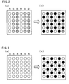
- Figure 2 shows the illuminating device in which three illuminating devices 1R, 1G, and 1B exist. A portion (a) in Figure 2 shows a state where all the LED chips 11 are turned on, and a portion (b) in Figure 2 shows a state where some of the LED chips 11 are turned off in the illuminating devices 1R, 1G, and 1B. The LED chips 11 that are turned off are shown by a black color in the Figure.
- Figure 3 is a front view showing the illuminating device 1 R shown in Figure 1. That is, the illuminating device 1 R is formed in such a manner that the LED chips 11 that emit a light in red are arranged in an array shape in one plane surface. A portion (a) in Figure 3 shows the state where all the LED chips 11 are turned on, and a portion (b) in Figure 3 shows the state where some of the LED chips 11 are turned off.
- the LED chips When turning off the LED chips 11, as shown in the portion (b) in Figure 2 and the portion (b) in Figure 3, the LED chips may be turned off in a dispersing fashion, but this is not always the case, and the LED chips may be turned off orderly from the LED chips located on an edge side.
- the LED chips 11 are caused to perform a pulse light-emission, and as shown in Figure 4, the amount of light may be controlled by changing a duty ratio of the pulse light-emission during each frame period (1V: vertical period).
- the configuration using the liquid crystal display panel is shown, however, the present invention is not limited to using the liquid crystal display panel. Instead, a display panel, a type in which each one of micro mirrors is driven singly (for example, a digital micro mirror device: DMD), may be used.
- a display panel a type in which each one of micro mirrors is driven singly (for example, a digital micro mirror device: DMD)
- DMD digital micro mirror device
- the illuminating devices 1R, 1G, and 1B are arranged in such a manner as to face respectively three of four side surfaces of the dichroic prism 4, and a light in white is emitted from the other side surface of the dichroic prism 4. Then, the light in white is irradiated onto a single panel DMD 9 via a lens 7 and a curved surface mirror 10.
- the light reflected by the single panel DMD 9 (full color image light) is projected by a projection lens 5.
- the illuminating devices 1R, 1G and 1B are arranged in such a manner as to face respectively three of four side surfaces of the dichroic prism 4, and the light in white is emitted from the other side surface of the dichroic prism 4. Then the light in white is guided to a total internal reflection (TIR) prism 30 via the lens 7. The light in white reflected by the total internal reflection prism 30 is guided to a color separation prism 31 formed of three prisms.
- TIR total internal reflection
- the lights in respective colors are guided to the DMDs for respective colors 9R, 9G, and 9B.
- Reflected lights (image lights in respective colors) therefrom are incident on the color separation prism 31 again, and emitted from the color separation prism 31 after becoming a full color image light.
- the full color image light emitted from the color separation prism 31 transmits the total internal reflection prism 30 and is projected by a projection lens 5.
- the configuration of the illuminating device 1 is not limited to the above-described configuration.
- a rod integrator instead of a pair of fly's eye lenses 13, it is possible to use a rod integrator.
- the solid light source is not limited to the light emitting diode (LED) and it is possible to use a laser diode, and the like.
- the optimal processing portion 21 may perform a three-level determination (dark, middle, bright) toward the input video signal and may control the amount of light and the driving of the panel under the three levels.
- the amount of emitted light of the solid light source is adjusted in accordance with the video signal, so that the more dark videos exit, the less the power is consumed. Moreover, there are such advantages that it is not necessary to have high cooling capacity and it is possible to reduce power consumption for cooling.
Landscapes
- Physics & Mathematics (AREA)
- General Physics & Mathematics (AREA)
- Optics & Photonics (AREA)
- Engineering & Computer Science (AREA)
- Theoretical Computer Science (AREA)
- Computer Hardware Design (AREA)
- Multimedia (AREA)
- Signal Processing (AREA)
- Spectroscopy & Molecular Physics (AREA)
- Chemical & Material Sciences (AREA)
- Crystallography & Structural Chemistry (AREA)
- Nonlinear Science (AREA)
- Mathematical Physics (AREA)
- Projection Apparatus (AREA)
- Control Of Indicators Other Than Cathode Ray Tubes (AREA)
- Liquid Crystal Display Device Control (AREA)
- Liquid Crystal (AREA)
Abstract
An optimal processing portion (21) inputs a video signal (RGB signals) and analyzes
1-frame video in the video signal. For example, if the intensity of red color is 0 percent in all
dots in 1-frame video, the optimal processing portion (21) applies to a light source gain
adjustment portion (22) a control signal for rendering a gain of the illuminating device (1R) 0
percent (minimum amount of light). The light source gain adjustment portion (22) receives the
control signal and controls power supply to the illuminating device (1R). In addition, the
optimal processing portion (21) applies a driving instruction for rendering the amount of light
transmission 0 percent with regard to all dots of the liquid crystal display panel (3R), for
example, to a LCD signal processing portion (23).
Description
The present invention relates to a projection type video display such as a liquid crystal
projector, and the like.
Generally, an illuminating device used for a liquid crystal projector, and etc., is formed
of a lamp such as an ultra-high pressure mercury lamp, a metal halide lamp, a xenon lamp,
and etc., and a parabolic reflector that renders the irradiating light a parallel light.
Furthermore, in recent years, from the viewpoint of a longer operating life, and a
power-saving, and the like, it is attempted to use a light-emitting diode (LED) as a light
source (see Japanese Patent Laying-open No.H10-186507).
However, the power-saving in the prior art is achieved by a low-power-consumption
operating characteristic of a solid light source itself, and a further power-saving illumination
device has not been realized.
In view of the foregoing circumstances, it is an object of the present invention to
provide a projection type video display capable of realizing a power-saving by using a solid
light source such as a light-emitting-diode, and the like.
In order to solve the above-mentioned problem, a projection type video display of the
present invention comprises a first solid light source that emits a light in red, a second solid
light source that emits a light in green, a third solid light source that emits a light in blue, a
display panel for receiving and modulating the lights in colors from the light sources, a means
for projecting a full color image light formed of the modulated lights in colors, a light source
adjustment means for adjusting an amount of emitted light of the solid light sources by
controlling power supplied thereto on the basis of video signal information, and a means for
controlling a driving signal to each display panel so as to correspond to an adjustment of the
amount of the emitted lights in respective colors.
With the above-described configuration, an amount of emitted light of the solid light
sources is adjusted in accordance with a video signal by controlling power supplied to the solid
light sources, so that the more dark videos exist, the less power is consumed. In addition, it is
not necessary to have high cooling capacity, and besides, it is possible to reduce power
consumption for cooling.
Each solid light source may be formed of being provided with a plurality of solid
light-emitting elements and the light source adjustment means may adjust an amount of emitted
light of each solid light source by controlling the number of pieces of light emission out of the
plurality of solid light-emitting elements. Or, it may be configured that each solid light source
is formed of being provided with a plurality of solid light-emitting elements and the light source
adjustment means adjusts the amount of emitted light of each solid light source by controlling
power supplied to each solid light emitting element. Or, it may be configured that each solid
light source is formed of being provided with a plurality of solid light-emitting elements and the
light source adjustment means causes each solid light-emitting element to perform a pulse
light-emission and adjusts the amount of emitted light of each solid light-emitting element by
controlling a duty ratio of the pulse light-emission.
The amount of emitted light of the solid light sources for respective colors may be
adjusted by controlling the power supplied thereto so as to obtain the highest value of respective
colors in 1-frame video in a state where a value of a gradation of the display panel is the highest.
This enables the power consumption to be reduced as much as possible.
The projection type video display may be configured that a light in white obtained by
combining lights in respective colors from respective light sources is guided to a single-panel
full color display panel as the display panel. Or, the projection type video display may be
configured that the light in white obtained by combining lights in respective colors from
respective light sources is separated and each of the lights in respective colors is respectively
guided to the red color-use display panel, the green color-use display panel, and the blue
color-use display panel as the display panel. Or, the projection type video display may be
configured that each of the lights in respective colors is guided to the red color-use display
panel, the green color-use display, and the blue color-use display panel as the light in respective
colors.
Hereinafter, a projection type video display according to an embodiment of the present
invention will be described referring to Figures 1 to 6.
Figure 1 is a diagram showing an optical system and a control system of a three-panel
projection type video display. This projection type video display is provided with three
illuminating devices 1 R, 1G, and 1B (Hereinafter, a numeral "1" is used when showing not
specifying each illuminating device). The light source 1 R emits a light in red, the light source
1 G emits a light in green, and the light source 1B emits a light in blue. The light emitted from
each of the illuminating devices 1 is guided by a convex lens 2 to liquid crystal display panels
3R, 3G, and 3B (Hereinafter, a numeral "3" is used when showing not specifying each liquid
crystal panel). Each liquid crystal display panel 3 is formed of being provided with an
incidence-side polarizing plate, a panel portion formed by sealing a liquid crystal between a
pair of glass plates (in which a dot electrode and an alignment film are formed), and an
emission-side polarizing plate. Modulated lights (image lights in respective colors) modulated
by passing through the liquid crystal display panels 3R, 3G, and 3B are combined by a dichroic
prism 4, and rendered color image light. The color image light is projected by a projection lens
5, and is displayed on a screen.
The illuminating device 1 is formed of a light source 12 in which LED chips 11 are
arranged in an array shape and lens cells 14 are arranged on a light-emission side of each of the
LED chips 11, and a pair of fly's eye lenses 13 that integrates and guides to the liquid crystal
panel 3 the light emitted from each of the LED chips 11 and rendered parallel by the lens cells
14. The pair of fly's eye lenses 13 is structured of a pair of lens clusters 13a, 13b, and each pair
of lenses guides the light emitted from each LED chip 11 to an entire surface of the liquid
crystal display panel 3. The LED chips 11 are molded by transparent resin and as a result of this
transparent resin being formed in a convex shape, the lens cells 14 are formed. The LED chip
11, the lens cell 14, and each lens in the lens cluster 13a are formed in a rectangular shape, and
further, an aspect ratio of the rectangular is coincident or approximately coincident with an
aspect ratio of the liquid crystal display panel 3. It is noted that the aspect ratios of the LED
chip 11, the lens cell 14, and each lens in the lens cluster 13a may be rendered different from the
aspect ratio of the liquid crystal display panel 3. In this case, it is preferable that an aspect ratio
of light flux guided to the liquid crystal panel 3 is rendered coincident or approximately
coincident with the aspect ratio of the liquid crystal panel 3 by using an anamorphic lens.
An optimal processing portion 21 inputs a video signal (RGB signals) and analyzes a
1-frame video in the video signal. Specifically, the optimal processing portion detects intensity
of red color (red color gradation signal), intensity of green color (green color gradation signal),
and intensity of blue color (blue color gradation signal) of respective dots forming 1-frame
video. Here, in order to simplify the description, it is assumed that the intensity of respective
colors is normally within a range of a 256-gradation, and this range is between 0 and 100
percent, an amount of light transmission of the liquid crystal display panel 3 is controlled by a
100-gradation, and as for each illuminating device 1, too, the amount of light is adjusted by
each 1 percent in a range of between 1 and 100 percent.
If the intensity of red color is 0 percent in all dots in the 1-frame video, the optimal
processing portion 21 applies to a light source gain adjustment portion 22 a control signal for
rendering a gain of the illuminating device 1R 0 percent (minimum amount of light). The light
source gain adjustment portion 22 receives the control signal and controls a power (voltage) to
be supplied to the illuminating device 1R. Moreover, the optimal processing portion 21 applies
to an LCD signal processing portion 23 a driving instruction for rendering the amount of light
transmission 0 percent, for example, with regard to all dots of the liquid crystal display panel
3R. The LCD signal processing portion 23 drives the dots of the liquid crystal display panel 3R
on the basis of the driving instruction.
When a highest value of the intensity of red color in the 1-frame video is 50 percent, as
for the dots of which value of the intensity of red color is 50 percent, the amount of light
transmission is 100 percent, and as for the illuminating device 1R, the amount of emitted light is
50 percent. With regard to the dots having the value of intensity of red color other than 50
percent, a correction corresponding to the amount of emitted light of the illuminating device
1R being rendered 50 percent may be applied to the original intensity of red color according to
the video signal. That is, the amount of emitted light of the solid light sources for respective
colors may be adjusted according to a power supply control such that the highest value of
respective colors in the 1-frame video is obtained in a state where a value of a gradation of the
display panel is the highest. Such the control enables a least amount of power to be consumed
in the illuminating device 1. Needless to say, the present invention is not limited to such the
control, and as for the dots of which value of the intensity of red color is 50 percent, such a
control as to render the amount of light transmission 70 percent and to render the amount of the
emitted light of the illuminating device 1R 70 percent may be performed. In this case, too, with
regard to the dots having the value of intensity of red color other than 50 percent, a correction
corresponding to the amount of emitted light of the illuminating device 1R being rendered 70
percent may be applied to the original intensity of red color according to the video signal.
In addition, a similar control may be performed also with regard to other colors. A
conventional projection type video display receives power supply in such a manner as to emit
light at a highest amount of light also in displaying black video. However, the projection type
video display according to the present invention is capable of rendering 0 (zero) the power
supply to the illuminating device 1, for example, in displaying the black video. As a result, it is
possible to greatly reduce the power consumption.
It is noted that, in the above-described configuration, the power (voltage) supplied to
each illuminating device 1 (that is, the LED chips 11) is controlled by the light source gain
adjustment portion 22, and however, the amount of emitted light of each illuminating device 1
may be adjusted by controlling the number of the LED chips 11 made to emit light. Figure 2
shows the illuminating device in which three illuminating devices 1R, 1G, and 1B exist. A
portion (a) in Figure 2 shows a state where all the LED chips 11 are turned on, and a portion (b)
in Figure 2 shows a state where some of the LED chips 11 are turned off in the illuminating
devices 1R, 1G, and 1B. The LED chips 11 that are turned off are shown by a black color in the
Figure. It is noted that the lights in respective colors are superposed and emitted from such the
illuminating device, so that the light may be guided to a single-panel full color display panel.
Or, the light may be divided into the lights in respective colors by a dichroic mirror and guided
to the display panels for respective colors. In addition, Figure 3 is a front view showing the
illuminating device 1 R shown in Figure 1. That is, the illuminating device 1 R is formed in such
a manner that the LED chips 11 that emit a light in red are arranged in an array shape in one
plane surface. A portion (a) in Figure 3 shows the state where all the LED chips 11 are turned
on, and a portion (b) in Figure 3 shows the state where some of the LED chips 11 are turned off.
When turning off the LED chips 11, as shown in the portion (b) in Figure 2 and the portion (b)
in Figure 3, the LED chips may be turned off in a dispersing fashion, but this is not always the
case, and the LED chips may be turned off orderly from the LED chips located on an edge side.
Furthermore, the LED chips 11 are caused to perform a pulse light-emission, and as
shown in Figure 4, the amount of light may be controlled by changing a duty ratio of the pulse
light-emission during each frame period (1V: vertical period).
Moreover, the configuration using the liquid crystal display panel is shown, however,
the present invention is not limited to using the liquid crystal display panel. Instead, a display
panel, a type in which each one of micro mirrors is driven singly (for example, a digital micro
mirror device: DMD), may be used. In the case of the single-panel projection type video
display, for example, as shown in Figure 5, the illuminating devices 1R, 1G, and 1B are
arranged in such a manner as to face respectively three of four side surfaces of the dichroic
prism 4, and a light in white is emitted from the other side surface of the dichroic prism 4.
Then, the light in white is irradiated onto a single panel DMD 9 via a lens 7 and a curved surface
mirror 10. The light reflected by the single panel DMD 9 (full color image light) is projected by
a projection lens 5. In addition, in the case of the three-panel projection type video display, for
example, as shown in Figure 6, the illuminating devices 1R, 1G and 1B are arranged in such a
manner as to face respectively three of four side surfaces of the dichroic prism 4, and the light in
white is emitted from the other side surface of the dichroic prism 4. Then the light in white is
guided to a total internal reflection (TIR) prism 30 via the lens 7. The light in white reflected by
the total internal reflection prism 30 is guided to a color separation prism 31 formed of three
prisms. Then, the lights in respective colors are guided to the DMDs for respective colors 9R,
9G, and 9B. Reflected lights (image lights in respective colors) therefrom are incident on the
color separation prism 31 again, and emitted from the color separation prism 31 after becoming
a full color image light. The full color image light emitted from the color separation prism 31
transmits the total internal reflection prism 30 and is projected by a projection lens 5.
The configuration of the illuminating device 1 is not limited to the above-described
configuration. For example, instead of a pair of fly's eye lenses 13, it is possible to use a rod
integrator. Also the solid light source is not limited to the light emitting diode (LED) and it is
possible to use a laser diode, and the like. In addition, the optimal processing portion 21 may
perform a three-level determination (dark, middle, bright) toward the input video signal and
may control the amount of light and the driving of the panel under the three levels.
As described above, with the present invention, the amount of emitted light of the solid
light source is adjusted in accordance with the video signal, so that the more dark videos exit,
the less the power is consumed. Moreover, there are such advantages that it is not necessary to
have high cooling capacity and it is possible to reduce power consumption for cooling.
Claims (8)
- A projection type video display, comprising:a first solid light source that emits a light in red;a second solid light source that emits a light in green;a third solid light source that emits a light in blue;a display panel for receiving and modulating said lights in colors from said light sources;a means for projecting a full color image light formed of said modulated lights in colors;a light source adjustment means for adjusting an amount of emitted light of said solid light sources by controlling power supplied thereto on the basis of video signal information; anda means for controlling a driving signal to each display panel so as to correspond to an adjustment of the amount of the emitted lights in respective colors.
- A projection type video display according to claim 1, wherein each solid light source is formed of being provided with a plurality of solid light-emitting elements, and said light source adjustment means controls an amount of emitted light of each solid light source by controlling the number of pieces of light emission out of the plurality of solid light-emitting elements.
- A projection type video display according to claim 1, wherein each solid light source is formed of being provided with a plurality of solid light-emitting elements, and said light source adjustment means adjusts an amount of emitted light of each solid light source by controlling power supplied to each solid light-emitting element.
- A projection type video display according to claim 1, wherein each solid light source is formed of being provided with a plurality of solid light-emitting elements, said light source adjustment means causes each solid light-emitting element to perform a pulse light-emission and adjusts an amount of emitted light of each solid light-emitting element by controlling a duty ratio of the pulse light-emission.
- A projection type video display according to any one of claims 1 to 4, wherein the amount of emitted light of said solid light sources for respective colors is adjusted by controlling the power supplied thereto so as to obtain the highest value of respective colors in 1-frame video in a state where a value of a gradation of the display panel is the highest.
- A projection type video display according to any one of claims 1 to 5, wherein a light in white obtained by combining lights in respective colors from respective light sources is guided to a single-panel full color display panel as said display panel.
- A projection type video display according to any one of claims 1 to 5, wherein a light in white obtained by combining lights in respective colors from respective light sources is separated, and each of the lights in respective colors is guided to a red color-use display panel, a green color-use display panel, and a blue color-use display panel as said display panel, respectively.
- A projection type video display according to any one of claims 1 to 5, wherein each of the lights in respective colors is guided to the red color-use display panel, the green color-use display panel, and the blue-color use display panel as the light in respective colors.
Applications Claiming Priority (3)
| Application Number | Priority Date | Filing Date | Title |
|---|---|---|---|
| JP2002377873 | 2002-12-26 | ||
| JP2002377873 | 2002-12-26 | ||
| PCT/JP2003/016835 WO2004059608A1 (en) | 2002-12-26 | 2003-12-25 | Projection type video display device |
Publications (2)
| Publication Number | Publication Date |
|---|---|
| EP1577872A1 true EP1577872A1 (en) | 2005-09-21 |
| EP1577872A4 EP1577872A4 (en) | 2008-11-26 |
Family
ID=32677410
Family Applications (1)
| Application Number | Title | Priority Date | Filing Date |
|---|---|---|---|
| EP03782910A Withdrawn EP1577872A4 (en) | 2002-12-26 | 2003-12-25 | Projection type video display device |
Country Status (6)
| Country | Link |
|---|---|
| US (1) | US7270425B2 (en) |
| EP (1) | EP1577872A4 (en) |
| JP (1) | JP4245563B2 (en) |
| KR (1) | KR100816971B1 (en) |
| CN (1) | CN100424547C (en) |
| WO (1) | WO2004059608A1 (en) |
Cited By (11)
| Publication number | Priority date | Publication date | Assignee | Title |
|---|---|---|---|---|
| WO2007138576A1 (en) * | 2006-05-25 | 2007-12-06 | Mirage Innovations Ltd. | Illumination system with optical integrator for an image projector |
| WO2008035259A1 (en) * | 2006-09-20 | 2008-03-27 | Koninklijke Philips Electronics N.V. | Dynamic gamut control |
| WO2008040308A1 (en) * | 2006-09-26 | 2008-04-10 | Osram Opto Semiconductors Gmbh | Optical projection device |
| EP1942373A2 (en) * | 2007-01-05 | 2008-07-09 | Hitachi, Ltd. | Projection type display apparatus and optical unit |
| US7492512B2 (en) | 2004-07-23 | 2009-02-17 | Mirage International Ltd. | Wide field-of-view binocular device, system and kit |
| US7499216B2 (en) | 2004-07-23 | 2009-03-03 | Mirage Innovations Ltd. | Wide field-of-view binocular device |
| US7573640B2 (en) | 2005-04-04 | 2009-08-11 | Mirage Innovations Ltd. | Multi-plane optical apparatus |
| US7625882B2 (en) | 2003-05-27 | 2009-12-01 | Vascular Biogenics Ltd. | Oxidized lipids and uses thereof in the treatment of inflammatory diseases and disorders |
| USRE42992E1 (en) | 2003-02-19 | 2011-12-06 | Mirage Innovations Ltd. | Chromatic planar optic display system |
| US8206743B2 (en) | 2000-11-17 | 2012-06-26 | Vascular Biogenics Ltd. | Promoters exhibiting endothelial cell specificity and methods of using same for regulation of angiogenesis |
| US8415318B2 (en) | 2001-10-19 | 2013-04-09 | Vascular Biogenics Ltd. | Polynucleotide constructs, pharmaceutical compositions and methods for targeted downregulation of angiogenesis and anticancer therapy |
Families Citing this family (46)
| Publication number | Priority date | Publication date | Assignee | Title |
|---|---|---|---|---|
| JP3909595B2 (en) * | 2003-04-23 | 2007-04-25 | セイコーエプソン株式会社 | Display device and dimming method thereof |
| WO2005031445A1 (en) * | 2003-09-30 | 2005-04-07 | Koninklijke Philips Electronics, N.V. | Light source array for lcd applications |
| JP4616577B2 (en) * | 2004-04-22 | 2011-01-19 | 株式会社日立製作所 | Video display device |
| JP4107266B2 (en) * | 2004-06-11 | 2008-06-25 | セイコーエプソン株式会社 | Display device and dimming method thereof |
| JP4731142B2 (en) * | 2004-09-16 | 2011-07-20 | 株式会社リコー | Color display device, projector, and eyepiece type display device |
| JP4254672B2 (en) * | 2004-09-21 | 2009-04-15 | 株式会社ニコン | Portable information equipment |
| CN101917498B (en) * | 2004-09-21 | 2012-06-13 | 株式会社尼康 | Mobile information device |
| US20110310357A1 (en) * | 2004-11-15 | 2011-12-22 | Kuo-Ching Chiang | Multiple rate projector |
| US9083781B2 (en) | 2004-11-15 | 2015-07-14 | Bascule Development Ag Llc | Portable image-capturing device with embedded projector |
| US7874486B2 (en) | 2004-11-15 | 2011-01-25 | Kuo-Ching Chiang | Portable communication device with DMD |
| US7178735B2 (en) * | 2004-11-15 | 2007-02-20 | Kuo Ching Chiang | Multi-function portable communication device |
| EP1830225B1 (en) | 2004-11-26 | 2013-12-25 | Nikon Corporation | Projector device |
| KR101306615B1 (en) * | 2004-12-23 | 2013-09-11 | 돌비 레버러토리즈 라이쎈싱 코오포레이션 | Wide color gamut displays |
| KR100718962B1 (en) * | 2004-12-28 | 2007-05-16 | 엘지전자 주식회사 | Projection display driving device |
| JP4736436B2 (en) * | 2005-01-20 | 2011-07-27 | 株式会社日立製作所 | Projection type display device and multi-screen display device |
| JP2006301325A (en) * | 2005-04-21 | 2006-11-02 | Victor Co Of Japan Ltd | Image display device |
| KR101189085B1 (en) * | 2005-07-14 | 2012-11-09 | 삼성디스플레이 주식회사 | Backlight unit and liquid crystal display having the same |
| JP5320661B2 (en) * | 2006-03-28 | 2013-10-23 | セイコーエプソン株式会社 | Image display device |
| JP5277518B2 (en) * | 2006-04-21 | 2013-08-28 | カシオ計算機株式会社 | Projection apparatus, display control method, and program |
| US8144172B2 (en) * | 2006-05-24 | 2012-03-27 | Panasonic Corporation | Color temperature correction device and display device |
| JP2007333140A (en) * | 2006-06-16 | 2007-12-27 | Bosch Corp | Electromagnetic proportional control valve for flow control and pump for fuel supply |
| JP4239107B2 (en) * | 2006-08-25 | 2009-03-18 | カシオ計算機株式会社 | Light source device and projector |
| US7468831B2 (en) * | 2007-02-20 | 2008-12-23 | Miradia, Inc. | Contrast with fast response light source |
| US20090153805A1 (en) * | 2007-12-14 | 2009-06-18 | Fu Zhun Precision Industry (Shen Zhen) Co., Ltd. | Portable projector with a heat dissipation system |
| US8011792B2 (en) * | 2007-12-28 | 2011-09-06 | Sanyo Electric Co., Ltd. | Lighting unit and projection display apparatus |
| TWI376562B (en) * | 2008-06-04 | 2012-11-11 | Delta Electronics Inc | Light transformation apparatus and light source apparatus comprising the same |
| JPWO2010064559A1 (en) * | 2008-12-05 | 2012-05-10 | 三洋電機株式会社 | Illumination device and projection display device |
| JP2010224316A (en) * | 2009-03-24 | 2010-10-07 | Sanyo Electric Co Ltd | Projection type video display |
| CN101988630B (en) * | 2009-07-31 | 2013-01-09 | 深圳市光峰光电技术有限公司 | Stage lighting system and method thereof for proving high-brightness white light |
| JP5436097B2 (en) * | 2009-08-25 | 2014-03-05 | 三菱電機株式会社 | Condensing optical system and projection-type image display device |
| US8714750B2 (en) * | 2010-01-21 | 2014-05-06 | Sony Corporation | Displaying projector status visibly |
| US8277049B2 (en) * | 2010-02-02 | 2012-10-02 | National Kaohsiung First University Of Science And Technology | Projector using LEDs as light sources |
| JP5703631B2 (en) | 2010-08-26 | 2015-04-22 | セイコーエプソン株式会社 | projector |
| TW201229653A (en) * | 2010-12-31 | 2012-07-16 | Bascule Dev Ag Llc | Transmitting color image projector and the method thereof |
| TWI418920B (en) * | 2011-03-31 | 2013-12-11 | Young Optics Inc | Projection apparatus |
| TWI446002B (en) * | 2011-04-29 | 2014-07-21 | Delta Electronics Inc | Light source apparatus |
| JP5999959B2 (en) * | 2012-04-05 | 2016-09-28 | 三菱電機株式会社 | Projection type projector |
| JP5984482B2 (en) * | 2012-04-26 | 2016-09-06 | 三菱電機株式会社 | Projection type projector |
| US20140211173A1 (en) * | 2013-01-30 | 2014-07-31 | 3M Innovative Properties Company | Optical projection subsystem |
| WO2014183583A1 (en) * | 2013-05-17 | 2014-11-20 | 深圳市绎立锐光科技开发有限公司 | Light-emitting device and stage lamp system |
| CN103391412B (en) * | 2013-07-23 | 2016-06-01 | 华东师范大学 | The method for displaying image of a kind of light-source brightness Automatic adjusument and device |
| JP2016180802A (en) * | 2015-03-23 | 2016-10-13 | キヤノン株式会社 | Projection control device, control method and program |
| CN107129931B (en) * | 2017-06-27 | 2023-04-18 | 中国计量科学研究院 | Biomolecule optical detector metering standard device and use method |
| CN111352287A (en) * | 2018-12-24 | 2020-06-30 | 深圳光峰科技股份有限公司 | Light source system and projection equipment |
| CN209590522U (en) * | 2019-04-16 | 2019-11-05 | 中强光电股份有限公司 | Lighting system and projection device |
| CN112596332B (en) * | 2020-12-23 | 2022-03-11 | 广景视睿科技(深圳)有限公司 | Projection system and projector |
Family Cites Families (26)
| Publication number | Priority date | Publication date | Assignee | Title |
|---|---|---|---|---|
| US6243055B1 (en) * | 1994-10-25 | 2001-06-05 | James L. Fergason | Optical display system and method with optical shifting of pixel position including conversion of pixel layout to form delta to stripe pattern by time base multiplexing |
| JPH10186507A (en) | 1996-10-31 | 1998-07-14 | Sanyo Electric Co Ltd | Rear projection display |
| US5971545A (en) * | 1997-06-25 | 1999-10-26 | Hewlett-Packard Company | Light source for projection display |
| JP3585097B2 (en) * | 1998-06-04 | 2004-11-04 | セイコーエプソン株式会社 | Light source device, optical device and liquid crystal display device |
| WO1999064912A1 (en) * | 1998-06-05 | 1999-12-16 | Seiko Epson Corporation | Light source and display device |
| JP2000214827A (en) * | 1999-01-21 | 2000-08-04 | Toray Ind Inc | Field sequential driving type color liquid crystal display |
| TW380213B (en) * | 1999-01-21 | 2000-01-21 | Ind Tech Res Inst | Illumination apparatus and image projection apparatus includes the same |
| JP2000221499A (en) | 1999-01-28 | 2000-08-11 | Sony Corp | Light source for image display device and image display device |
| JP4590647B2 (en) * | 1999-07-30 | 2010-12-01 | 日東光学株式会社 | Light source device and projector device |
| KR20010050623A (en) * | 1999-10-04 | 2001-06-15 | 모리시타 요이찌 | Display technique for high gradation degree |
| JP2001343706A (en) * | 2000-05-31 | 2001-12-14 | Sony Corp | Video display device |
| EP1303796B1 (en) * | 2000-07-10 | 2005-04-27 | Corporation For Laser Optics Research | Systems and methods for speckle reduction through bandwidth enhancement |
| JP2002278505A (en) * | 2001-03-19 | 2002-09-27 | Canon Inc | Image processing device |
| JP3640173B2 (en) * | 2001-04-02 | 2005-04-20 | ソニー株式会社 | Image display device |
| CA2452064A1 (en) * | 2001-06-26 | 2003-01-03 | Honeywell International Inc. | Projection system utilizing fiber optic illumination |
| KR100444986B1 (en) * | 2001-09-29 | 2004-08-21 | 삼성전자주식회사 | Illumination system and a projector imploying it |
| KR100440959B1 (en) * | 2001-11-08 | 2004-07-21 | 삼성전자주식회사 | Illumination system and projection system employing it |
| US6932477B2 (en) * | 2001-12-21 | 2005-08-23 | Koninklijke Philips Electronics N.V. | Apparatus for providing multi-spectral light for an image projection system |
| JP2004111357A (en) * | 2002-07-09 | 2004-04-08 | Topcon Corp | Light source device |
| US6769772B2 (en) * | 2002-10-11 | 2004-08-03 | Eastman Kodak Company | Six color display apparatus having increased color gamut |
| JP2004184777A (en) * | 2002-12-04 | 2004-07-02 | Nec Viewtechnology Ltd | Light source device and projection type display device |
| WO2004080053A2 (en) * | 2003-02-28 | 2004-09-16 | Florida Atlantic University | Displays using solid state light sources |
| KR100970720B1 (en) * | 2003-04-15 | 2010-07-16 | 삼성전자주식회사 | Projection type image display device |
| JP2004335992A (en) * | 2003-04-18 | 2004-11-25 | Victor Co Of Japan Ltd | Light source unit and projection display device applied with the light source unit |
| US7360900B2 (en) * | 2004-03-10 | 2008-04-22 | Seiko Epson Corporation | Illuminating apparatus, image display apparatus, and projector |
| JP2005284051A (en) * | 2004-03-30 | 2005-10-13 | Hitachi Ltd | Semiconductor light emitting element, light source unit using the same, optical unit, and image display device |
-
2003
- 2003-12-25 CN CNB200380107244XA patent/CN100424547C/en not_active Expired - Fee Related
- 2003-12-25 WO PCT/JP2003/016835 patent/WO2004059608A1/en not_active Ceased
- 2003-12-25 KR KR1020057011937A patent/KR100816971B1/en not_active Expired - Fee Related
- 2003-12-25 US US10/540,544 patent/US7270425B2/en not_active Expired - Fee Related
- 2003-12-25 JP JP2004562950A patent/JP4245563B2/en not_active Expired - Fee Related
- 2003-12-25 EP EP03782910A patent/EP1577872A4/en not_active Withdrawn
Cited By (17)
| Publication number | Priority date | Publication date | Assignee | Title |
|---|---|---|---|---|
| US8206743B2 (en) | 2000-11-17 | 2012-06-26 | Vascular Biogenics Ltd. | Promoters exhibiting endothelial cell specificity and methods of using same for regulation of angiogenesis |
| US8158611B2 (en) | 2000-11-24 | 2012-04-17 | Vascular Biogenics Ltd. | Methods employing and compositions containing defined oxidized phospholipids for prevention and treatment of atherosclerosis |
| US7893291B2 (en) | 2000-11-24 | 2011-02-22 | Vascular Biogenics Ltd. | Methods employing and compositions containing defined oxidized phospholipids for prevention and treatment of atherosclerosis |
| US8415318B2 (en) | 2001-10-19 | 2013-04-09 | Vascular Biogenics Ltd. | Polynucleotide constructs, pharmaceutical compositions and methods for targeted downregulation of angiogenesis and anticancer therapy |
| USRE42992E1 (en) | 2003-02-19 | 2011-12-06 | Mirage Innovations Ltd. | Chromatic planar optic display system |
| US7973023B2 (en) | 2003-05-27 | 2011-07-05 | Vascular Biogenics Ltd. | Oxidized lipids and uses thereof in the treatment of inflammatory diseases and disorders |
| US7625882B2 (en) | 2003-05-27 | 2009-12-01 | Vascular Biogenics Ltd. | Oxidized lipids and uses thereof in the treatment of inflammatory diseases and disorders |
| US7902176B2 (en) | 2003-05-27 | 2011-03-08 | Vascular Biogenics Ltd. | Oxidized lipids and uses thereof in the treatment of inflammatory diseases and disorders |
| US8501715B2 (en) | 2003-05-27 | 2013-08-06 | Vascular Biogenics Ltd. | Oxidized lipids and uses thereof in the treatment of inflammatory diseases and disorders |
| US7499216B2 (en) | 2004-07-23 | 2009-03-03 | Mirage Innovations Ltd. | Wide field-of-view binocular device |
| US7492512B2 (en) | 2004-07-23 | 2009-02-17 | Mirage International Ltd. | Wide field-of-view binocular device, system and kit |
| US7573640B2 (en) | 2005-04-04 | 2009-08-11 | Mirage Innovations Ltd. | Multi-plane optical apparatus |
| WO2007138576A1 (en) * | 2006-05-25 | 2007-12-06 | Mirage Innovations Ltd. | Illumination system with optical integrator for an image projector |
| WO2008035259A1 (en) * | 2006-09-20 | 2008-03-27 | Koninklijke Philips Electronics N.V. | Dynamic gamut control |
| US8390643B2 (en) | 2006-09-20 | 2013-03-05 | Koninklijke Philips Electronics N.V. | Dynamic gamut control |
| WO2008040308A1 (en) * | 2006-09-26 | 2008-04-10 | Osram Opto Semiconductors Gmbh | Optical projection device |
| EP1942373A2 (en) * | 2007-01-05 | 2008-07-09 | Hitachi, Ltd. | Projection type display apparatus and optical unit |
Also Published As
| Publication number | Publication date |
|---|---|
| EP1577872A4 (en) | 2008-11-26 |
| CN100424547C (en) | 2008-10-08 |
| KR20050088218A (en) | 2005-09-02 |
| US20060050245A1 (en) | 2006-03-09 |
| JPWO2004059608A1 (en) | 2006-04-27 |
| KR100816971B1 (en) | 2008-03-26 |
| CN1729502A (en) | 2006-02-01 |
| WO2004059608A1 (en) | 2004-07-15 |
| JP4245563B2 (en) | 2009-03-25 |
| US7270425B2 (en) | 2007-09-18 |
Similar Documents
| Publication | Publication Date | Title |
|---|---|---|
| US7270425B2 (en) | Projection type video display | |
| US7766490B2 (en) | Multi-color primary light generation in a projection system using LEDs | |
| CN100401183C (en) | Projector | |
| EP3561594B1 (en) | Illumination system, projection device and operating method thereof | |
| US7530708B2 (en) | Surface emitting light source and projection display device using the same | |
| US9081268B2 (en) | Lighting device and projection-type display apparatus including lighting device | |
| KR100841532B1 (en) | Image display | |
| EP1596247A1 (en) | Light source with four or five colours and projector | |
| US8593579B2 (en) | Projection display | |
| TW200400365A (en) | Image display device and projector | |
| US20130271673A1 (en) | Projector and image display method | |
| CN108227356B (en) | Projection display system | |
| US7237909B2 (en) | Optical member, illuminating device, and projection type video display | |
| US7360901B2 (en) | Cross dichroic mirror, illuminating device, and projection type video display | |
| US7852329B2 (en) | Image display apparatus | |
| CN100565330C (en) | Light supply apparatus and projector | |
| EP1627527B1 (en) | Illumination system for videoprojector utilizing one or more led diodes matrices | |
| JP4186662B2 (en) | Illumination device and projection device | |
| US20050213344A1 (en) | Light source device for illumination | |
| JP2001268588A (en) | Lighting device and projection display device | |
| JP4466035B2 (en) | Lighting device and projector | |
| US20240411216A1 (en) | Selective Illumination of a Spatial Light Modulator | |
| JP2006184666A (en) | Light source device and image forming apparatus |
Legal Events
| Date | Code | Title | Description |
|---|---|---|---|
| PUAI | Public reference made under article 153(3) epc to a published international application that has entered the european phase |
Free format text: ORIGINAL CODE: 0009012 |
|
| 17P | Request for examination filed |
Effective date: 20050621 |
|
| AK | Designated contracting states |
Kind code of ref document: A1 Designated state(s): DE FR GB |
|
| A4 | Supplementary search report drawn up and despatched |
Effective date: 20081027 |
|
| 17Q | First examination report despatched |
Effective date: 20110315 |
|
| STAA | Information on the status of an ep patent application or granted ep patent |
Free format text: STATUS: THE APPLICATION HAS BEEN WITHDRAWN |
|
| 18W | Application withdrawn |
Effective date: 20130916 |