EP1577802A1 - Computer program for designing a microfluidic device - Google Patents
Computer program for designing a microfluidic device Download PDFInfo
- Publication number
- EP1577802A1 EP1577802A1 EP04026273A EP04026273A EP1577802A1 EP 1577802 A1 EP1577802 A1 EP 1577802A1 EP 04026273 A EP04026273 A EP 04026273A EP 04026273 A EP04026273 A EP 04026273A EP 1577802 A1 EP1577802 A1 EP 1577802A1
- Authority
- EP
- European Patent Office
- Prior art keywords
- piece
- information
- flow path
- treating member
- sample
- Prior art date
- Legal status (The legal status is an assumption and is not a legal conclusion. Google has not performed a legal analysis and makes no representation as to the accuracy of the status listed.)
- Withdrawn
Links
Images



Classifications
-
- G—PHYSICS
- G16—INFORMATION AND COMMUNICATION TECHNOLOGY [ICT] SPECIALLY ADAPTED FOR SPECIFIC APPLICATION FIELDS
- G16H—HEALTHCARE INFORMATICS, i.e. INFORMATION AND COMMUNICATION TECHNOLOGY [ICT] SPECIALLY ADAPTED FOR THE HANDLING OR PROCESSING OF MEDICAL OR HEALTHCARE DATA
- G16H20/00—ICT specially adapted for therapies or health-improving plans, e.g. for handling prescriptions, for steering therapy or for monitoring patient compliance
- G16H20/10—ICT specially adapted for therapies or health-improving plans, e.g. for handling prescriptions, for steering therapy or for monitoring patient compliance relating to drugs or medications, e.g. for ensuring correct administration to patients
-
- G—PHYSICS
- G06—COMPUTING OR CALCULATING; COUNTING
- G06F—ELECTRIC DIGITAL DATA PROCESSING
- G06F30/00—Computer-aided design [CAD]
-
- B—PERFORMING OPERATIONS; TRANSPORTING
- B01—PHYSICAL OR CHEMICAL PROCESSES OR APPARATUS IN GENERAL
- B01L—CHEMICAL OR PHYSICAL LABORATORY APPARATUS FOR GENERAL USE
- B01L3/00—Containers or dishes for laboratory use, e.g. laboratory glassware; Droppers
- B01L3/50—Containers for the purpose of retaining a material to be analysed, e.g. test tubes
- B01L3/502—Containers for the purpose of retaining a material to be analysed, e.g. test tubes with fluid transport, e.g. in multi-compartment structures
- B01L3/5027—Containers for the purpose of retaining a material to be analysed, e.g. test tubes with fluid transport, e.g. in multi-compartment structures by integrated microfluidic structures, i.e. dimensions of channels and chambers are such that surface tension forces are important, e.g. lab-on-a-chip
Definitions
- the present invention relates to a program for designing a treating member to be used when treatments such as chemical reactions are conducted as an automated process, and a system for providing a service to design a treating member using the program concerned.
- a chemical treatment process is constituted with a sequence of individual treatments referred to as unit chemical operations such as centrifugal separation and mixing/reaction.
- unit chemical operations such as centrifugal separation and mixing/reaction.
- Various processes have been developed, and these various chemical treatment processes require complicated operations; generally, individual treatment steps are carried out by hand sequentially in such a way that samples and reagents are placed in glass flasks and test tubes.
- automated devices are available.
- Examples of such automated devices include a centrifugal separator in which components in a sample solution inside a test tube are separated by specific gravity by revolving the test tube, an evaporator device in which a flask is made to rotate and the liquid inside the flask is evaporated, and a general-purpose robot device which sucks up a trace of liquid inside a test tube and transfers the liquid to another test tube or a reaction vessel.
- WO 00/78455 describes a microstructure and a method for examination using amplification as a device automating by rotary drive a particular chemical treatment process and a particular chemical analysis, both having been predetermined.
- a DNA mixture solution is made to pass through a glass filter as an inorganic substrate, and thereafter made to pass through a cleaning liquid and an eluent, thus merely the DNA being recovered.
- the glass filter is arranged on a rotatable structure, and reagents such as the cleaning liquid and the eluent are held respectively in individual reagent reservoirs in the structure.
- the respective regents are made to flow by the centrifugal force generated by the rotation of the structure, and the valves arranged in the micro flow paths connecting between the respective reagent reservoirs and the glass filter are opened, the reagents being thereby made to pass through the glass filter.
- microstructures are needed to be designed in compliance with the plural unit chemical operations constituting the chemical treatment process.
- a program or a system which provides microstructures in compliance with an arbitrary chemical treatment process has not yet been known.
- the present invention takes as its object the provision of a program for designing a treating member which program can provide a treating member automating a sequential process in compliance with an arbitrary treatment process and a system for providing a service system to design the treating member.
- a program for designing a treating member involved in the present invention which program has achieved the aforementioned object may include a step for acquiring a piece of input information including a treatment sequence; and a step for designing a flow path, along which a sample moves, based on the above described piece of input information. According to the present program, there can be constructed a piece of drive control information about the designed treating member.
- the system for designing a treating member involved in the present invention may include a step for acquiring a piece of design information about a flow path along which a sample moves, designed based on a piece of input information including a treatment sequence; a step for creating a piece of control information for controlling a treating-member fabrication unit based on the above described piece of design information; and a step for outputting the above described piece of control information to the above described treating-member fabrication unit.
- the system for designing a treating member involved in the present invention may include a step for acquiring a piece of input information including a treatment sequence; a step for designing a flow path along which a sample moves based on the above described piece of input information; a step for creating a piece of control information for controlling a treating-member fabrication unit based on a piece of design information about the designed flow path; and a step for outputting the above described piece of control information to the above described treating-member fabrication unit.
- the piece of input information further include one or more pieces of information selected from the group consisting of a piece of operation information about the above described sample, a piece of treatment condition information about the above described sample, and a piece of information associated with samples.
- the flow path can be designed by optimizing the piece of shape information, read out from the database in which the treatment sequence and the piece of shape information are stored to correlate with each other, based on a piece of information included in the piece of input information.
- a treating member which automates a sequential process in compliance with an arbitrary chemical treatment process. More specifically, according to the program for designing a treating member and the system for designing a treating member, involved in the present invention, there can be designed a treating member for carrying out an arbitrary process, based on a piece of information about the treatment sequence included in the piece of input information.
- the system for designing the treating member according to the present invention includes a user terminal 1 belonging to the system user side, a provision terminal 2 for designing a flow path in the treating member to be used in a chemical or other treatment process, and a treating-member fabrication unit 3 for fabricating the treating member.
- the user terminal 1 and the provision terminal 2 are connected to each other through the intermediary of communication network such as Internet and intranet, and can exchange various types of data with each other.
- the unit 3 for fabricating the treating member may be directly connected to the provision terminal 2, or may be connected to the provision terminal 2 through the intermediary of communication networks in a communicatable manner.
- a treating member to actualize the treatment sequence desired by a user of the system is designed on the provision terminal 2, and the treating member is fabricated by the unit 3 for fabricating the treating member based on this design. More specifically, on the provision terminal 2, according to a processing program to be described later in detail, there are executed a step for acquiring a piece of input information including the treatment sequence desired by the user of the system and a step for designing the flow path in the treating member based on the above described piece of input information.
- a chemical treatment process will be described as a treatment process in which a treating member fabricated by taking advantage of the present system for designing a treating member.
- the treatment process using the treating member is not limited to a chemical treatment process, but may be a treatment process such as a process in which merely a physical treatment is carried out.
- a device for carrying out a chemical treatment process includes a fixing jig 20 for placing and holding a treating member 10 on the top thereof, a rotary drive mechanism 21 to turn the fixing jig 20, a control section 30 to control the turning of the fixing jig 20 by the rotary drive mechanism 21.
- the rotary drive mechanism 21 includes a drive member 22 such as a stepping motor and a shaft 23 connected to the drive member 22.
- the fixing jig 20 is fixed to the shaft 23 of the rotary drive mechanism 21.
- a pair of treating members 10 can be disposed symmetrically with the shaft 23 of the rotary drive mechanism 21 as a center therebetween.
- the treating member 10 is arranged with an inlet 11 for introducing a sample in the vicinity of one end thereof, and an outlet 14 for recovering the sample in the vicinity of the other end thereof.
- the treating member 10 has a flow path consisting of a groove 13 along which a sample flows and a reaction section 12 to apply a predetermined treatment to the sample, between the inlet 11 and the outlet 14.
- the treating member 10 like this can be fabricated by molding a resin such as polypropylene.
- the treating member 10 is temporarily fixed onto the fixing jig 20 in such a way that the end in the vicinity of which the inlet 11 is arranged is located on the side of the shaft 23 of the rotary drive mechanism 21 and the other end in the vicinity of which the outlet 14 is arranged is located to be away from the shaft 23.
- the device for carrying out a chemical treatment process configured as described above is operated as follows. Firstly, an operator drops a sample into the inlet 11 of the treating member 10, and thereafter the treating member 10 is fixed onto the fixing jig 20. Additionally, the operator inputs predetermined treatment conditions (for example, the rotation velocity, rotation time and stop time) into the control section 30 for the purpose of carrying out a desired chemical treatment process.
- predetermined treatment conditions for example, the rotation velocity, rotation time and stop time
- the rotary drive mechanism 21 repeats rotation and halt.
- the treating member 10 rotates together with the fixing jig 20 with the aid of the action of the rotary drive mechanism 21, the sample migrates toward the outer circumference owing to centrifugal force. Additionally, when the rotation is halted, the migration of the sample is also halted. Consequently, by appropriately repeating the rotation and halt, the sample dropped into the treating member 10 can be appropriately made to migrate and halted toward the circumference. More specifically, according to the treatment conditions input by the operator, the sample is guided into the flow path consisting of the groove 13 and the reaction section 12, and thus a desired chemical treatment process can be applied. In the reaction section 12, a reaction of the sample is started.
- Plural reaction sections may be arranged at positions downstream of the reaction section 12, namely, at positions on the circumference side of the reaction section 12, as the case may be. By further applying rotation and halt, the sample is successively delivered and different unit chemical operations can be sequentially carried out.
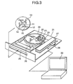
- the chemical treatment process can also be carried out by means of such a device as shown in Fig. 3.
- the device shown in Fig. 3 is a device in which a chemical treatment process is carried out by using a treating member 10 made of a disc.
- sample introduction inlets 11 are arranged in the vicinity of the rotational center of the disc.
- flow paths each consisting of a micro reaction section 12 and the like are arranged.
- the treating member 10 also comprises a reagent charging section 16 which contains a reagent in advance.
- a flow path blocking section 15 made of a thermosensitive material is arranged between the reagent charging section 16 and a reaction section 12.
- the flow path blocking section 15 prevents the sample charged in the reagent charging section 16 from flowing into the reaction section 12.
- the flow path blocking section 15 has a function such that the section is fused when the section receives an amount of heat larger than a certain value, and thus the flow path is opened.
- the treating member 10 may be covered with a case although the case is not shown in the figure.
- the surface of the case concerned is provided a slit for use in introducing therethrough a sample into the treating member 10 and for use in operating or detecting therethrough the flow of the sample.
- the drive device 21 is arranged with an insertion slot 25 for inserting the treating member 10.
- a fixing jig 20 is arranged at a position away from the insertion slot.
- the fixing jig 20 is connected to a rotary mechanism 26.
- a sample handling device 22 for controlling the flow of the sample, a heating device 23 for heating the sample and a measurement device 24 for measuring the reaction condition of the sample are arranged on a drive arm 27.
- the measurement device 24 is arranged with an irradiation light source and a photodetector for detecting the intensity and spectrum of the reflected light.
- the drive arm 27 is connected to an arm drive mechanism 28 for scanning from the center of the circle of the treating member 10 toward the circumference thereof.
- the drive mechanism 21 is connected to an input unit 30. Alternatively, the drive mechanism 21 and the input unit 30 may be integrated into one unit. With the configuration described above, the operations are developed as follows.
- a sample is dropped into the introduction inlets 11 of the treating member 10.
- the treating member 10 is inserted into the insertion slot 25.
- the treating member 10 is set onto the fixing jig 20 in a manner cooperating with the insertion slot 25. The condition thus formed completes the preparation for startup.
- the operator reads out a piece of operation control information from a memory device in the input unit, corresponding to the chemical treatment process for the treating member 10 piece with the aid of the input unit 30.
- the treating member 10 starts to rotate.
- the sample is starts to flow toward the circumference owing to the centrifugal force accompanying the rotation.
- the disc decreases the rotation velocity, the treating member 10 is thereby made to rotate slowly, and the flow path blocking section 15 on the treating member 10 is adjusted in position to face the sample handling device 22.
- a predetermined beam of light is irradiated from the sample handling device 22 onto the flow path blocking section 15.
- the flow path blocking section 15 is heated by the beam of light and fused, and the reagent charging section 16 and the reaction section 12 are made to communicatively connected with each other.
- the treating member 10 starts to rotate once again from this condition, the sample in the reagent charging section 16 flows into the reaction section 12 owing to centrifugal force.
- the sample and a reagent can be mixed together in the reaction section 12.
- the rotation velocity is once again decreased, and the above described reaction section 12 is in turn adjusted in position to face the heating device 23.
- the reaction section 12 is heated by the radiation heat due to a heater in the heating device 23.
- the reaction is promoted by this heating.
- the arm drive mechanism 27 operates to locate the measurement device 24 directly above the above described reaction section 12. Thereafter, a predetermined beam of light is irradiated toward the reaction section 12 from the irradiation light source of the measurement device 24.
- the photodetector in the measurement device 24 can find the extent of reaction, the concentrations and the like of the components contributed to the reaction in the sample by detecting a set of optical information including the absorption spectrum, fluorescence or the like in the reaction section 12.
- the flow path blocking section 15 is fused by irradiating a beam of light from the sample handling device 22 to communicate the reagent charging section 16 with the reaction section 12; however, as is obvious, the blockade may be removed by a mechanical boring operation or the like. Additionally, also in the heating device 23, heating may be made by direct contact with a heater. Alternatively, the whole treating member 10 may be heated.
- a treating member 10 capable of carrying out plural different unit chemical operations, an arbitrary chemical treatment process can be carried out.
- description will be made on the program for designing a treating member for use in acquiring a piece of design information about the treating member 10 on the occasion of fabricating the treating member 10 to be used in the aforementioned chemical treatment process.
- the treating member 10 there is adopted a treating member for carrying out operation to separate micro particles such as bacteria present in urine, environmental water and the like.
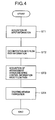
- the present program for designing a treating member can design a treating member 10 on the provision terminal 2 according to the flowchart as shown in Fig. 4.
- the present program for designing a treating member is installed in the provision terminal, and designs on the provision terminal a treating member for carrying out the treatment sequence desired by a system user.
- a piece of input information including the treatment sequence is acquired from the user terminal 1.
- the treatment sequence means a piece of information representing as a time series the unit chemical operations included in the chemical treatment process desired by the system user.
- the piece of input information includes, in addition to the piece of information representing the treatment sequence, a piece of liquid sample related information such as the liquid amount and liquid viscosity of the analyte sample used in chemical treatment process, a piece of treatment condition information, a piece of information about the apparatus owned by the system user, a piece of ID information specific to the system user and the like.
- the unit chemical operations include a centrifugal separation operation, a mixing operation, a fractionation operation and the like.
- a mixing operation it is preferable that a set of information about the liquid amount and the composition of the solution to be the object of mixing is concurrently acquired as a part of the piece of input information.
- a fractionation operation it is preferable that a piece of information about the liquid amount and the component to be fractionated of the solution is concurrently acquired as a part of the piece of input information.
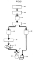
- the piece of input information acquired in step 1 is decomposed into pieces of information about the flow path on the rotary member, for example, with the aid of the system for designing a treating member as shown in Fig. 5 and Fig. 6. More specifically, the step 2 selects a piece of path shape/dimension information for each of the plural unit chemical operations included in the piece of input information.
- the present program can also select a piece of path shape/dimension information in compliance with the plural unit chemical operations included in the piece of input information, by use of a database in which a piece of information about the unit chemical operations and a piece of path shape/dimension information appropriate to the unit chemical operations concerned are stored to correlate with each other.
- a piece of input information covering the above described unit chemical operations (1) to (8) is acquired, a piece of design information about a treating member is acquired in the following way as shown in Fig. 6.
- a flow path element for use in centrifugal separation extending along the centrifugal force direction (a radial direction) is given to be a fundamental shape.
- the fundamental shape is corrected on the basis thereof, and the piece of flow path shape/dimension information corresponding to the unit chemical operation (1) is acquired.
- the piece of flow path shape/dimension information is temporarily accumulated in a recording device 51 as a piece of flow path information for carrying out the unit chemical operation (1).
- a piece of input information acquired includes the sample composition, the physical property values of a material to be precipitated and the like, a piece of information about the acceleration to be exerted by the centrifugal separation, the time required and the like is obtained by calculation based on the piece of input information.
- a piece of operation information about the device for carrying out the chemical treatment process can be obtained based on these pieces of information.
- the set of operation information obtained is accumulated in the recording device 51.
- a capillary flow path element for fractionation transversely extending from the side face of the flow path element for centrifugal separation designed in the above described (1) and bent to the upstream side, is given to be a fundamental shape.
- the liquid flow in the capillary flow path element for fractionation is described.
- the centrifugal separation is completed, and the rotation of the rotary member is halted; then, the clear supernatant liquid in the flow path element for centrifugal separation fills the capillary flow path element for fractionation owing to the capillary force.
- the outlet of the capillary flow path element for fractionation is situated in an outer position away from the rotation center than the inlet, the clear supernatant liquid in the flow path element for centrifugal separation starts to continuously flow owing to the siphon effect.
- the piece of physical property information representing the surface tension of the sample solution and the like, included in the piece of input information, the width of the flow path and the like for the capillary flow are generated as a piece of design information, and on the generated piece of design information, the fundamental shape is corrected to acquire the piece of flow path shape/dimension information corresponding to the unit chemical operation (2).
- the piece of flow path shape/dimension information is temporarily accumulated in the recording device 51 as a piece of flow path information for carrying out the unit chemical operation (2).
- the minimum time for the clear supernatant liquid to fill the capillary flow path element for fractionation and the minimum time needed for complete flow out of the clear supernatant liquid from the interior of the flow path element for centrifugal separation by means of a syphon are obtained by calculation.
- a piece of operation information about the device for carrying out the chemical treatment process can be obtained based on these pieces of information.
- the piece of operation information obtained is accumulated in the recording device 51.
- a piece of flow path shape/dimension information corresponding to the unit chemical operation (3) as a first step, there is given a flow path element for mixing which forms one flow path from two confluent flow paths extending along the direction of the centrifugal force (the radial direction).
- a flow path element for mixing which forms one flow path from two confluent flow paths extending along the direction of the centrifugal force (the radial direction).
- specific dimensions and the like based on the piece of information about the liquid amount, the viscosity, the composition and the like of the solution to be an object of mixing, included in the piece of input information, the fundamental shape is corrected on the basis thereof, and the piece of flow path shape/dimension information corresponding to the unit chemical operation (3) is acquired.
- the piece of flow path shape/dimension information is temporarily accumulated in the recording device 51 as a piece of flow path information for carrying out the unit chemical operation (3).
- the fundamental shape of the above described flow path element for mixing can be corrected in such a way that a large number of micro protrusions or a large number of micro convexities and concavities are arranged inside the flow path element.
- a piece of operation information including the flow velocities with which the two liquids should be respectively introduced into the flow path element for mixing there can be obtained by calculation a piece of operation information including the flow velocities with which the two liquids should be respectively introduced into the flow path element for mixing.
- a piece of operation information about the device for carrying out the chemical treatment process can be obtained based on these pieces of information.
- the obtained piece of operation information is accumulated in the recording device 51.
- the fundamental shape is corrected according to a piece of information included in the piece of input information; thus, there can be obtained pieces of path shape/dimension information respectively corresponding to the unit chemical operations (4) to (7).
- the unit chemical operations (4) to (7) there can be acquired pieces of operation information about the device with which the chemical treatment process is carried out.
- the unit chemical operation (8) is an operation which recovers the precipitate formed by the unit chemical operation (6), no particular piece of flow path shape/dimension information is needed.
- the pieces of flow path shape/dimension information for carrying out the respective unit chemical operations (1) to (7) and the pieces of operation information in the respective unit chemical operations can be sequentially accumulated in the recording device 51.
- step 3 the pieces of flow path shape/dimension information, accumulated in the recording device 51, for carrying out the respective unit chemical operations are read out, and the flow path of the treating member 10 is designed by means of a device 52 for designing a treating member. More specifically, the device 52 for designing a treating member, as a first step, arranges the pieces of path shape/dimension information for carrying out the respective unit chemical operations according to the time series, sequentially from the inlet toward the outlet. Specifically, as shown in Fig.
- the pieces of flow path shape/dimension information corresponding to the respective unit chemical operations (1) to (7) are read out, the arrangement designs for the respective flow paths on the treating member is carried out, and the respective flow paths are arranged in such a way that the flow paths are shifted away little by little from the rotation center along the radial direction.
- the piece of arrangement information is accumulated in a device 53 for recording a treating member structure.
- the present step because the locations along the radial direction from the center of the respective flow path elements are determined, based on the locations along the radial direction and the pieces of operation information needed for the respective flow path elements, there are acquired pieces of drive information including the rotation numbers and the like in carrying out the respective treatments. More specifically, in the present step, there can be acquired a piece of drive control information about the device with which the chemical treatment process is carried out.
- the piece of drive control information is accumulated in a device 60 for recording the piece of drive information about the treating member. Incidentally, the piece of drive information accumulated in the device 60 for recording the piece of drive control information about a treating member is transmitted to the user terminal 1.
- step 4 the piece of design information about the treating member in the device 53 for recording a treating member structure is transmitted to a tool 70 for high speed processing of a treating member.
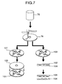
- the tool 70 for high speed processing of a treating member fabricates the treating member, based on the received piece of design information about the treating member, in a manner as shown in Fig. 7.
- the fabrication process of a treating member shown in Fig. 7 is an example, and the fabrication of a treating member based on the piece of design information about the treating member is not limited to the method shown in Fig. 7, but any other methods may be applied.
- the surface 78 of a blank workpiece coated with a negative photosensitive resin is exposed to light in conformity with the flow path shape with the aid of a laser 76. Then, a corrosive liquid is applied onto the surface 78 of the blank workpiece to remove the exposed area. Consequently, a treating member 101 on which the desired flow path is formed can be fabricated, and is used in a condition such that a lid 102 is adhered thereto.
- a stamper 103 may be made in such a way that the surface 78 of a blank workpiece coated with a positive photosensitive resin is exposed to light in conformity with the flow path shape with the aid of the laser 76, and a corrosive liquid is applied onto the surface to remove the resin while the flow path portion is left intact.
- a treating member 104 can be fabricated in such a way that a resin is poured onto the stamper 103, and after curing, the resin is released.
- the treating member fabricated as described above is used in a device owned by the user side and shown in Fig. 3, and repeats rotation/halt according to the piece of drive control information.
- the piece of drive control information may be made to be arbitrarily alterable in pieceting on the user side.
- chemical experiments based on altering various types of parameters can be easily carried out.
- a system and a program for designing a treating member involved in the present invention there can be acquired a piece of design information about a treating member desired by the user, and concurrently a piece of drive control information about the treating member fabricated based on the concerned piece of design information. Accordingly, on the user side, by merely presenting at least a desired treatment sequence, there can be obtained a piece of drive control information about the device to be used for the treating member capable of carrying out the treatment sequence concerned and for the treatment process using the treating member concerned.
- the design of the treating member is carried out on the provision terminal side; however, the technical scope of the present invention is not limited to the first best embodiment.
- the system for designing a treating member may be a system in which a piece of design information about the treating member 10 is acquired on the user terminal 1 belonging to the system user side, and the acquired piece of design information is output toward the provision terminal.
- a program for designing a treating member is installed in the user terminal 1, and steps 1 up to 3 shown in Fig. 4 are executed on the user terminal 1.
- the program for designing a treating member may be arranged to be downloaded into the user terminal 1 after the system user have received certification from the provision terminal 2.
- the user terminal 1 outputs the piece of design information about the treating member acquired at step 3 toward the provision terminal.
- the acquired piece of design information about the treating member is transmitted to the tool 70 for high speed processing of the treating member (step 4).
- the tool 70 for high speed processing of the treating member can fabricate the treating member in a manner as shown in Fig. 7, based on the received piece of design information about the treating member.
- the piece of design information about the treating member is acquired by use of the program for designing a treating member, and consequently, no piece of input information is needed to be transmitted from the user terminal 1 to the provision terminal 2.
- the piece of input information includes pieces of information which the system user does not want to disclose such as a piece of information about the unit chemical operations of the chemical treatment process desired by the user side.
- the piece of design information about the treating member is output from the system user to the provision terminal 2 side, and hence a piece of information which the system user does not want to disclose can be concealed from the provider side.
Landscapes
- Engineering & Computer Science (AREA)
- Physics & Mathematics (AREA)
- Health & Medical Sciences (AREA)
- Theoretical Computer Science (AREA)
- Geometry (AREA)
- Medicinal Chemistry (AREA)
- General Physics & Mathematics (AREA)
- Evolutionary Computation (AREA)
- Computer Hardware Design (AREA)
- Chemical & Material Sciences (AREA)
- Bioinformatics & Cheminformatics (AREA)
- General Engineering & Computer Science (AREA)
- Epidemiology (AREA)
- General Health & Medical Sciences (AREA)
- Medical Informatics (AREA)
- Primary Health Care (AREA)
- Public Health (AREA)
- Automatic Analysis And Handling Materials Therefor (AREA)
Abstract
The present invention relates to a computer program embodied on a computer readable medium for designing a treating member (10). The computer program contains a first code segment adapted to acquiring a piece of input information containing a treatment sequence (ST1); and a second code segment adapted to designing a flow path along which a sample moves, based on the piece of input information (ST2).
Description
The present invention relates to a program
for designing a treating member to be used when
treatments such as chemical reactions are conducted as
an automated process, and a system for providing a
service to design a treating member using the program
concerned.
In general, a chemical treatment process is
constituted with a sequence of individual treatments
referred to as unit chemical operations such as
centrifugal separation and mixing/reaction. Various
processes have been developed, and these various
chemical treatment processes require complicated
operations; generally, individual treatment steps are
carried out by hand sequentially in such a way that
samples and reagents are placed in glass flasks and
test tubes. However, for some operations, automated
devices are available. Examples of such automated
devices include a centrifugal separator in which
components in a sample solution inside a test tube are
separated by specific gravity by revolving the test
tube, an evaporator device in which a flask is made to
rotate and the liquid inside the flask is evaporated,
and a general-purpose robot device which sucks up a
trace of liquid inside a test tube and transfers the
liquid to another test tube or a reaction vessel.
WO 00/78455 describes a microstructure and a
method for examination using amplification as a device
automating by rotary drive a particular chemical
treatment process and a particular chemical analysis,
both having been predetermined. In this device, by use
of a method for purifying and separating a nucleic acid
mixture, described in JP 8-501321 A, a DNA mixture
solution is made to pass through a glass filter as an
inorganic substrate, and thereafter made to pass
through a cleaning liquid and an eluent, thus merely
the DNA being recovered. The glass filter is arranged
on a rotatable structure, and reagents such as the
cleaning liquid and the eluent are held respectively in
individual reagent reservoirs in the structure. The
respective regents are made to flow by the centrifugal
force generated by the rotation of the structure, and
the valves arranged in the micro flow paths connecting
between the respective reagent reservoirs and the glass
filter are opened, the reagents being thereby made to
pass through the glass filter.
As can be seen clearly from the above
description on conventional techniques, in a sequential
chemical treatment process composed of a sequence of
different unit chemical operations, the individual unit
chemical operations are needed to be carried out by
hand or by combining devices; the state of affairs is
such that there have not yet been proposed a technique
and a device which can completely automate a sequential
process from beginning to end. In the aforementioned
WO 00/78455, there is disclosed a technique in which for
a particular treatment process of gene extraction,
a sequence of operations are completely automated by
making liquids flow by exerting centrifugal force
through rotary driving; however, this technique cannot
meet arbitrary chemical treatment processes.
Furthermore, for the purpose of carrying out
an arbitrary chemical treatment process,
microstructures are needed to be designed in compliance
with the plural unit chemical operations constituting
the chemical treatment process. However, there has not
yet been known a program or a system which provides
microstructures in compliance with an arbitrary
chemical treatment process.
Consequently, the present invention takes as
its object the provision of a program for designing a
treating member which program can provide a treating
member automating a sequential process in compliance
with an arbitrary treatment process and a system for
providing a service system to design the treating
member.
A program for designing a treating member
involved in the present invention which program has
achieved the aforementioned object may include a step for
acquiring a piece of input information including a
treatment sequence; and a step for designing a flow path,
along which a sample moves, based on the above described
piece of input information. According to the present
program, there can be constructed a piece of drive
control information about the designed treating member.
On the other hand, the system for designing a
treating member involved in the present invention may
include a step for acquiring a piece of design
information about a flow path along which a sample moves,
designed based on a piece of input information including a
treatment sequence; a step for creating a piece of control
information for controlling a
treating-member fabrication unit based on the above
described piece of design information; and a step for
outputting the above described piece of control
information to the above described treating-member
fabrication unit. In the present system, there can be
constructed a piece of drive control information about
the designed treating member, and there can be output the
piece of drive control information to the terminal having
output the piece of design information.
Additionally, the system for designing a
treating member involved in the present invention may
include a step for acquiring a piece of input information
including a treatment sequence; a step for designing a
flow path along which a sample moves based
on the above described piece of input information; a
step for creating a piece of control information for
controlling a treating-member fabrication unit based on
a piece of design information about the designed flow
path; and a step for outputting the above described
piece of control information to the above described
treating-member fabrication unit.
It is preferable that in the program and
system for designing the treating member, involved in
the present invention, in addition to a piece of
information about the treatment sequence, the piece of
input information further include one or more pieces of
information selected from the group consisting of a
piece of operation information about the above
described sample, a piece of treatment condition
information about the above described sample, and a
piece of information associated with samples. In the
program and system for designing the treating member,
involved in the present invention, the flow path can be
designed by optimizing the piece of shape information,
read out from the database in which the treatment
sequence and the piece of shape information are stored
to correlate with each other, based on a piece of
information included in the piece of input information.
According to the present invention, there can
be provided a treating member which automates a
sequential process in compliance with an arbitrary
chemical treatment process. More specifically,
according to the program for designing a treating
member and the system for designing a treating member,
involved in the present invention, there can be
designed a treating member for carrying out an
arbitrary process, based on a piece of information
about the treatment sequence included in the piece of
input information.
Other objects, features and advantages of the
invention will become apparent from the following
description of the embodiments of the invention taken
in conjunction with the accompanying drawings.
Detailed description will be made below on
the program for designing the treating member and the
system for designing the treating member, both involved
in the present invention, with reference to the
accompanying drawings.
As shown in Fig. 1, the system for designing
the treating member according to the present invention
includes a user terminal 1 belonging to the system user
side, a provision terminal 2 for designing a flow path
in the treating member to be used in a chemical or
other treatment process, and a treating-member
fabrication unit 3 for fabricating the treating member.
In the present system, the user terminal 1 and the
provision terminal 2 are connected to each other
through the intermediary of communication network such
as Internet and intranet, and can exchange various
types of data with each other. Incidentally, in the
present system, the unit 3 for fabricating the treating
member may be directly connected to the provision
terminal 2, or may be connected to the provision
terminal 2 through the intermediary of communication
networks in a communicatable manner.
In the present system, a treating member to
actualize the treatment sequence desired by a user of
the system is designed on the provision terminal 2, and
the treating member is fabricated by the unit 3 for
fabricating the treating member based on this design.
More specifically, on the provision terminal 2,
according to a processing program to be described later
in detail, there are executed a step for acquiring a
piece of input information including the treatment
sequence desired by the user of the system and a step
for designing the flow path in the treating member
based on the above described piece of input
information.
Firstly, a chemical treatment process will be
described as a treatment process in which a treating
member fabricated by taking advantage of the present
system for designing a treating member. Incidentally,
the treatment process using the treating member is not
limited to a chemical treatment process, but may be a
treatment process such as a process in which merely a
physical treatment is carried out.
As shown in Fig. 2, a device for carrying out
a chemical treatment process includes a fixing jig 20
for placing and holding a treating member 10 on the top
thereof, a rotary drive mechanism 21 to turn the fixing
jig 20, a control section 30 to control the turning of
the fixing jig 20 by the rotary drive mechanism 21.
Into the control section 30, for example, the
rotational velocity, time of rotation, stop time and
the like of the fixing jig 20 are input, and the
control section 30 controls the rotary drive mechanism
21 according to this piece of input information. The
rotary drive mechanism 21 includes a drive member 22
such as a stepping motor and a shaft 23 connected to
the drive member 22. The fixing jig 20 is fixed to the
shaft 23 of the rotary drive mechanism 21. On the
fixing jig 20, a pair of treating members 10 can be
disposed symmetrically with the shaft 23 of the rotary
drive mechanism 21 as a center therebetween.
The treating member 10 is arranged with an
inlet 11 for introducing a sample in the vicinity of
one end thereof, and an outlet 14 for recovering the
sample in the vicinity of the other end thereof. The
treating member 10 has a flow path consisting of a
groove 13 along which a sample flows and a reaction
section 12 to apply a predetermined treatment to the
sample, between the inlet 11 and the outlet 14. The
treating member 10 like this can be fabricated by
molding a resin such as polypropylene.
The treating member 10 is temporarily fixed
onto the fixing jig 20 in such a way that the end in
the vicinity of which the inlet 11 is arranged is
located on the side of the shaft 23 of the rotary drive
mechanism 21 and the other end in the vicinity of which
the outlet 14 is arranged is located to be away from
the shaft 23.
The device for carrying out a chemical
treatment process configured as described above is
operated as follows. Firstly, an operator drops a
sample into the inlet 11 of the treating member 10, and
thereafter the treating member 10 is fixed onto the
fixing jig 20. Additionally, the operator inputs
predetermined treatment conditions (for example, the
rotation velocity, rotation time and stop time) into
the control section 30 for the purpose of carrying out
a desired chemical treatment process.
Thereafter, according to the input
procedures, the rotary drive mechanism 21 repeats
rotation and halt. When the treating member 10 rotates
together with the fixing jig 20 with the aid of the
action of the rotary drive mechanism 21, the sample
migrates toward the outer circumference owing to
centrifugal force. Additionally, when the rotation is
halted, the migration of the sample is also halted.
Consequently, by appropriately repeating the rotation
and halt, the sample dropped into the treating member
10 can be appropriately made to migrate and halted
toward the circumference. More specifically, according
to the treatment conditions input by the operator, the
sample is guided into the flow path consisting of the
groove 13 and the reaction section 12, and thus a
desired chemical treatment process can be applied. In
the reaction section 12, a reaction of the sample is
started. Plural reaction sections (not shown in the
figure) may be arranged at positions downstream of the
reaction section 12, namely, at positions on the
circumference side of the reaction section 12, as the
case may be. By further applying rotation and halt,
the sample is successively delivered and different unit
chemical operations can be sequentially carried out.
Incidentally, in the above described
explanation, description is made on the case where the
procedures of the chemical treatment process are input
each time; however, as is obvious, a recording medium
on which procedures have been beforehand recorded may
be provided and operations may be carried out
sequentially by reading out therefrom a piece of
information about the procedures.
Additionally, the chemical treatment process
can also be carried out by means of such a device as
shown in Fig. 3. The device shown in Fig. 3 is a
device in which a chemical treatment process is carried
out by using a treating member 10 made of a disc.
In the treating member 10, sample
introduction inlets 11 are arranged in the vicinity of
the rotational center of the disc. On the disc surface
of the treating member 10, flow paths each consisting
of a micro reaction section 12 and the like are
arranged. The treating member 10 also comprises a
reagent charging section 16 which contains a reagent in
advance. However, a flow path blocking section 15 made
of a thermosensitive material is arranged between the
reagent charging section 16 and a reaction section 12.
The flow path blocking section 15 prevents the sample
charged in the reagent charging section 16 from flowing
into the reaction section 12. The flow path blocking
section 15 has a function such that the section is
fused when the section receives an amount of heat
larger than a certain value, and thus the flow path is
opened.
Incidentally, the treating member 10 may be
covered with a case although the case is not shown in
the figure. In the case where the treating member 10
is covered with a case, the surface of the case
concerned is provided a slit for use in introducing
therethrough a sample into the treating member 10 and
for use in operating or detecting therethrough the flow
of the sample.
The drive device 21 is arranged with an
insertion slot 25 for inserting the treating member 10.
A fixing jig 20 is arranged at a position away from the
insertion slot. The fixing jig 20 is connected to a
rotary mechanism 26. A sample handling device 22 for
controlling the flow of the sample, a heating device 23
for heating the sample and a measurement device 24 for
measuring the reaction condition of the sample are
arranged on a drive arm 27. The measurement device 24
is arranged with an irradiation light source and a
photodetector for detecting the intensity and spectrum
of the reflected light. The drive arm 27 is connected
to an arm drive mechanism 28 for scanning from the
center of the circle of the treating member 10 toward
the circumference thereof. The drive mechanism 21 is
connected to an input unit 30. Alternatively, the
drive mechanism 21 and the input unit 30 may be
integrated into one unit. With the configuration
described above, the operations are developed as
follows.
Firstly, a sample is dropped into the
introduction inlets 11 of the treating member 10. The
treating member 10 is inserted into the insertion slot
25. The treating member 10 is set onto the fixing jig
20 in a manner cooperating with the insertion slot 25.
The condition thus formed completes the preparation for
startup.
In the next place, the operator reads out a
piece of operation control information from a memory
device in the input unit, corresponding to the chemical
treatment process for the treating member 10 piece with
the aid of the input unit 30. With a startup command,
the treating member 10 starts to rotate. The sample is
starts to flow toward the circumference owing to the
centrifugal force accompanying the rotation. After a
predetermined elapsed time, the disc decreases the
rotation velocity, the treating member 10 is thereby
made to rotate slowly, and the flow path blocking
section 15 on the treating member 10 is adjusted in
position to face the sample handling device 22.
A predetermined beam of light is irradiated
from the sample handling device 22 onto the flow path
blocking section 15. The flow path blocking section 15
is heated by the beam of light and fused, and the
reagent charging section 16 and the reaction section 12
are made to communicatively connected with each other.
When the treating member 10 starts to rotate once again
from this condition, the sample in the reagent charging
section 16 flows into the reaction section 12 owing to
centrifugal force. Thus, the sample and a reagent can
be mixed together in the reaction section 12.
The rotation velocity is once again
decreased, and the above described reaction section 12
is in turn adjusted in position to face the heating
device 23. The reaction section 12 is heated by the
radiation heat due to a heater in the heating device
23. The reaction is promoted by this heating. After
heating for a predetermined time, the arm drive
mechanism 27 operates to locate the measurement device
24 directly above the above described reaction section
12. Thereafter, a predetermined beam of light is
irradiated toward the reaction section 12 from the
irradiation light source of the measurement device 24.
The photodetector in the measurement device 24 can find
the extent of reaction, the concentrations and the like
of the components contributed to the reaction in the
sample by detecting a set of optical information
including the absorption spectrum, fluorescence or the
like in the reaction section 12.
In the above described example, the flow path
blocking section 15 is fused by irradiating a beam of
light from the sample handling device 22 to communicate
the reagent charging section 16 with the reaction
section 12; however, as is obvious, the blockade may be
removed by a mechanical boring operation or the like.
Additionally, also in the heating device 23, heating
may be made by direct contact with a heater.
Alternatively, the whole treating member 10 may be
heated.
In the above described Example, description
has been made on the mixing operation of one sample
with one reagent; however, as is obvious, many
reactions can be combined stepwise by arranging plural
reagents and plural reaction vessels, and plural
blocking sections corresponding thereto along a
direction toward the circumference. In addition to
reactions by mixing, component separation can be made
possible by arranging a chromatographic function on the
way of the flow path. Additionally, increase of the
rotation number makes it possible to give the treating
member a function to separate components in the vessel
based on the difference in specific gravity.
According to the above described example, for
an arbitrary chemical treatment process, it comes to be
possible to carry out the arbitrary chemical treatment
process by using a treating member 10 consistent with
the process. Additionally, in the treating member 10
placed in a case, samples and reagents are not
scattered during its rotation, so that an extremely
safe chemical treatment is possible.
As described above, by using a treating
member 10 capable of carrying out plural different unit
chemical operations, an arbitrary chemical treatment
process can be carried out. In the next place,
description will be made on the program for designing a
treating member for use in acquiring a piece of design
information about the treating member 10 on the
occasion of fabricating the treating member 10 to be
used in the aforementioned chemical treatment process.
In the following description, as an example of the
treating member 10, there is adopted a treating member
for carrying out operation to separate micro particles
such as bacteria present in urine, environmental water
and the like.
The present program for designing a treating
member can design a treating member 10 on the provision
terminal 2 according to the flowchart as shown in Fig.
4. In other words, the present program for designing a
treating member is installed in the provision terminal,
and designs on the provision terminal a treating member
for carrying out the treatment sequence desired by a
system user.
In the flowchart shown in Fig. 4, firstly in
step 1 (represented by "ST1" in Fig. 4, and the
following steps being represented similarly), a piece
of input information including the treatment sequence
is acquired from the user terminal 1. Here, the
treatment sequence means a piece of information
representing as a time series the unit chemical
operations included in the chemical treatment process
desired by the system user. The piece of input
information includes, in addition to the piece of
information representing the treatment sequence, a
piece of liquid sample related information such as the
liquid amount and liquid viscosity of the analyte
sample used in chemical treatment process, a piece of
treatment condition information, a piece of information
about the apparatus owned by the system user, a piece
of ID information specific to the system user and the
like.
In particular, the unit chemical operations
include a centrifugal separation operation, a mixing
operation, a fractionation operation and the like.
When the piece of information representing the
treatment sequence covers a mixing operation, it is
preferable that a set of information about the liquid
amount and the composition of the solution to be the
object of mixing is concurrently acquired as a part of
the piece of input information. Additionally, when the
piece of information representing the treatment
sequence covers a fractionation operation, it is
preferable that a piece of information about the liquid
amount and the component to be fractionated of the
solution is concurrently acquired as a part of the
piece of input information.
Specifically, as an example, there is
acquired a piece of input information covering the
sequential unit chemical operations represented by the
following operations (1) to (8).
In the next place, in the step 2, the piece
of input information acquired in step 1 is decomposed
into pieces of information about the flow path on the
rotary member, for example, with the aid of the system
for designing a treating member as shown in Fig. 5 and
Fig. 6. More specifically, the step 2 selects a piece
of path shape/dimension information for each of the
plural unit chemical operations included in the piece
of input information. For example, the present program
can also select a piece of path shape/dimension
information in compliance with the plural unit chemical
operations included in the piece of input information,
by use of a database in which a piece of information
about the unit chemical operations and a piece of path
shape/dimension information appropriate to the unit
chemical operations concerned are stored to correlate
with each other.
Specifically, when a piece of input
information covering the above described unit chemical
operations (1) to (8) is acquired, a piece of design
information about a treating member is acquired in the
following way as shown in Fig. 6.
Firstly, by making a flow path designing tool
50 retrieve the database, as a piece of flow path
shape/dimension information corresponding to the unit
chemical operation (1), a flow path element for use in
centrifugal separation extending along the centrifugal
force direction (a radial direction) is given to be a
fundamental shape. In the next place, there are given
specific dimensions including the length and width of
the flow path in compliance with the piece of sample
liquid amount information included in the piece of
input information, the fundamental shape is corrected
on the basis thereof, and the piece of flow path
shape/dimension information corresponding to the unit
chemical operation (1) is acquired. The piece of flow
path shape/dimension information is temporarily
accumulated in a recording device 51 as a piece of flow
path information for carrying out the unit chemical
operation (1).
When a piece of input information acquired
includes the sample composition, the physical property
values of a material to be precipitated and the like, a
piece of information about the acceleration to be
exerted by the centrifugal separation, the time
required and the like is obtained by calculation based
on the piece of input information. In this case, as
for the unit chemical operation (1), a piece of
operation information about the device for carrying out
the chemical treatment process can be obtained based on
these pieces of information. The set of operation
information obtained is accumulated in the recording
device 51.
In the next place, by making the flow path
designing tool 50 retrieve the database, as a piece of
flow path shape/dimension information corresponding to
the unit chemical operation (2), in the first instance,
a capillary flow path element for fractionation,
transversely extending from the side face of the flow
path element for centrifugal separation designed in the
above described (1) and bent to the upstream side, is
given to be a fundamental shape. The liquid flow in
the capillary flow path element for fractionation is
described. As a first step, the centrifugal separation
is completed, and the rotation of the rotary member is
halted; then, the clear supernatant liquid in the flow
path element for centrifugal separation fills the
capillary flow path element for fractionation owing to
the capillary force. When the rotation is started once
again, because the outlet of the capillary flow path
element for fractionation is situated in an outer
position away from the rotation center than the inlet,
the clear supernatant liquid in the flow path element
for centrifugal separation starts to continuously flow
owing to the siphon effect. Then, based on the piece
of physical property information representing the
surface tension of the sample solution and the like,
included in the piece of input information, the width
of the flow path and the like for the capillary flow
are generated as a piece of design information, and on
the generated piece of design information, the
fundamental shape is corrected to acquire the piece of
flow path shape/dimension information corresponding to
the unit chemical operation (2). The piece of flow
path shape/dimension information is temporarily
accumulated in the recording device 51 as a piece of
flow path information for carrying out the unit
chemical operation (2).
If the surface tension coefficient, the
viscosity, etc. of the clear supernatant liquid to be
fractionated are acquired as a piece of input
information, based on these pieces of information, the
minimum time for the clear supernatant liquid to fill
the capillary flow path element for fractionation and
the minimum time needed for complete flow out of the
clear supernatant liquid from the interior of the flow
path element for centrifugal separation by means of a
syphon are obtained by calculation. In this case, as
for the unit chemical operation (2), a piece of
operation information about the device for carrying out
the chemical treatment process can be obtained based on
these pieces of information. The piece of operation
information obtained is accumulated in the recording
device 51.
In the next place, as a piece of flow path
shape/dimension information corresponding to the unit
chemical operation (3), as a first step, there is given
a flow path element for mixing which forms one flow
path from two confluent flow paths extending along the
direction of the centrifugal force (the radial
direction). In the next place, there are given
specific dimensions and the like based on the piece of
information about the liquid amount, the viscosity, the
composition and the like of the solution to be an
object of mixing, included in the piece of input
information, the fundamental shape is corrected on the
basis thereof, and the piece of flow path
shape/dimension information corresponding to the unit
chemical operation (3) is acquired. The piece of flow
path shape/dimension information is temporarily
accumulated in the recording device 51 as a piece of
flow path information for carrying out the unit
chemical operation (3).
Incidentally, on the occasion of the unit
chemical operation (3), there can be obtained a piece
of information about the viscosities and affinities of
two liquids to be mixed together based on the database.
Additionally, when one liquid is an aqueous solution
and the other liquid is an organic solvent, and
accordingly there is needed an operation in which the
two liquids are mutually, finely dispersed and
emulsified, the fundamental shape of the above
described flow path element for mixing can be corrected
in such a way that a large number of micro protrusions
or a large number of micro convexities and concavities
are arranged inside the flow path element.
Additionally, based on the pieces of physical
property value information about the two liquids to be
mixed together, there can be obtained by calculation a
piece of operation information including the flow
velocities with which the two liquids should be
respectively introduced into the flow path element for
mixing. In this case, for the unit chemical operation
(3), a piece of operation information about the device
for carrying out the chemical treatment process can be
obtained based on these pieces of information. The
obtained piece of operation information is accumulated
in the recording device 51.
As described below, similarly to the
aforementioned (1) to (3), there is also given a
fundamental shape to each of the unit chemical
operations (4) to (7), the fundamental shape is
corrected according to a piece of information included
in the piece of input information; thus, there can be
obtained pieces of path shape/dimension information
respectively corresponding to the unit chemical
operations (4) to (7). Additionally, in a similar
manner, for the unit chemical operations (4) to (7),
there can be acquired pieces of operation information
about the device with which the chemical treatment
process is carried out. Incidentally, because the unit
chemical operation (8) is an operation which recovers
the precipitate formed by the unit chemical operation
(6), no particular piece of flow path shape/dimension
information is needed.
In the above described manner, the pieces of
flow path shape/dimension information for carrying out
the respective unit chemical operations (1) to (7) and
the pieces of operation information in the respective
unit chemical operations can be sequentially
accumulated in the recording device 51.
In the next place, in step 3, the pieces of
flow path shape/dimension information, accumulated in
the recording device 51, for carrying out the
respective unit chemical operations are read out, and
the flow path of the treating member 10 is designed by
means of a device 52 for designing a treating member.
More specifically, the device 52 for designing a
treating member, as a first step, arranges the pieces
of path shape/dimension information for carrying out
the respective unit chemical operations according to
the time series, sequentially from the inlet toward the
outlet. Specifically, as shown in Fig. 6, the pieces
of flow path shape/dimension information corresponding
to the respective unit chemical operations (1) to (7)
are read out, the arrangement designs for the
respective flow paths on the treating member is carried
out, and the respective flow paths are arranged in such
a way that the flow paths are shifted away little by
little from the rotation center along the radial
direction. The piece of arrangement information is
accumulated in a device 53 for recording a treating
member structure.
Additionally, in the present step, because
the locations along the radial direction from the
center of the respective flow path elements are
determined, based on the locations along the radial
direction and the pieces of operation information
needed for the respective flow path elements, there are
acquired pieces of drive information including the
rotation numbers and the like in carrying out the
respective treatments. More specifically, in the
present step, there can be acquired a piece of drive
control information about the device with which the
chemical treatment process is carried out. The piece
of drive control information is accumulated in a device
60 for recording the piece of drive information about
the treating member. Incidentally, the piece of drive
information accumulated in the device 60 for recording
the piece of drive control information about a treating
member is transmitted to the user terminal 1.
On the other hand, in step 4, the piece of
design information about the treating member in the
device 53 for recording a treating member structure is
transmitted to a tool 70 for high speed processing of a
treating member. The tool 70 for high speed processing
of a treating member fabricates the treating member,
based on the received piece of design information about
the treating member, in a manner as shown in Fig. 7.
Incidentally, the fabrication process of a treating
member shown in Fig. 7 is an example, and the
fabrication of a treating member based on the piece of
design information about the treating member is not
limited to the method shown in Fig. 7, but any other
methods may be applied.
According to the method shown in Fig. 7, as a
first step, based on the piece of flow path shape
information, the surface 78 of a blank workpiece coated
with a negative photosensitive resin is exposed to
light in conformity with the flow path shape with the
aid of a laser 76. Then, a corrosive liquid is applied
onto the surface 78 of the blank workpiece to remove
the exposed area. Consequently, a treating member 101
on which the desired flow path is formed can be
fabricated, and is used in a condition such that a lid
102 is adhered thereto.
Alternatively, a stamper 103 may be made in
such a way that the surface 78 of a blank workpiece
coated with a positive photosensitive resin is exposed
to light in conformity with the flow path shape with
the aid of the laser 76, and a corrosive liquid is
applied onto the surface to remove the resin while the
flow path portion is left intact. In this case, a
treating member 104 can be fabricated in such a way
that a resin is poured onto the stamper 103, and after
curing, the resin is released.
The treating member fabricated as described
above is used in a device owned by the user side and
shown in Fig. 3, and repeats rotation/halt according to
the piece of drive control information. Incidentally,
the piece of drive control information may be made to
be arbitrarily alterable in pieceting on the user side.
Hereby, chemical experiments based on altering various
types of parameters can be easily carried out.
As described above, according to a system and
a program for designing a treating member involved in
the present invention, there can be acquired a piece of
design information about a treating member desired by
the user, and concurrently a piece of drive control
information about the treating member fabricated based
on the concerned piece of design information.
Accordingly, on the user side, by merely presenting at
least a desired treatment sequence, there can be
obtained a piece of drive control information about the
device to be used for the treating member capable of
carrying out the treatment sequence concerned and for
the treatment process using the treating member
concerned.
In the aforementioned first best embodiment,
based on the piece of input information entered by the
system user, the design of the treating member is
carried out on the provision terminal side; however,
the technical scope of the present invention is not
limited to the first best embodiment.
In other words, as a second best embodiment
applied with the present invention, the system for
designing a treating member may be a system in which a
piece of design information about the treating member
10 is acquired on the user terminal 1 belonging to the
system user side, and the acquired piece of design
information is output toward the provision terminal.
In this case, a program for designing a treating member
is installed in the user terminal 1, and steps 1 up to
3 shown in Fig. 4 are executed on the user terminal 1.
In this connection, the program for designing a
treating member may be arranged to be downloaded into
the user terminal 1 after the system user have received
certification from the provision terminal 2.
Additionally, the user terminal 1 outputs the
piece of design information about the treating member
acquired at step 3 toward the provision terminal.
Hereby, on the provision terminal 2 side, the acquired
piece of design information about the treating member
is transmitted to the tool 70 for high speed processing
of the treating member (step 4). Also in the present
system, the tool 70 for high speed processing of the
treating member can fabricate the treating member in a
manner as shown in Fig. 7, based on the received piece
of design information about the treating member.
In the present system, on the user terminal 1
on the system user side, the piece of design
information about the treating member is acquired by
use of the program for designing a treating member, and
consequently, no piece of input information is needed
to be transmitted from the user terminal 1 to the
provision terminal 2. The piece of input information
includes pieces of information which the system user
does not want to disclose such as a piece of
information about the unit chemical operations of the
chemical treatment process desired by the user side.
According to the present system, merely the piece of
design information about the treating member is output
from the system user to the provision terminal 2 side,
and hence a piece of information which the system user
does not want to disclose can be concealed from the
provider side.
It should be further understood by those
skilled in the art that although the foregoing
description has been made on embodiments of the
invention, the invention is not limited thereto and
various changes and modifications may be made without
departing from the spirit of the invention and the
scope of the appended claims.
Claims (12)
- A computer program embodied on a computer readable medium for designing a treating member (10), comprising:a first code segment adapted to acquiring a piece of input information comprising a treatment sequence (ST1); anda second code segment adapted to designing a flow path along which a sample moves, based on said piece of input information (ST2).
- The computer program according to claim 1, wherein said piece of input information further comprises one or more pieces of information selected from the group consisting of a piece of physical property value information about said sample, a piece of treatment condition information about said sample, and a piece of liquid sample related information.
- The computer program according to claim 1 or 2, wherein said flow path is designed by optimizing a piece of shape information, read out from a database in which the treatment sequence and the piece of shape information are stored to correlate with each other, based on a piece of information included in said piece of input information.
- The computer program according to at least one of claims 1 to 3, further comprising a third segment adapted to outputting a piece of design information about the designed flow path.
- The computer program according to at least one of claims 1 to 4, further comprising a fourth segment adapted to constructing a piece of drive control information about the designed treating member.
- A system for providing a service to design a treating member (10), the system comprising the steps of:acquiring a piece of design information about a flow path along which a sample moves, designed based on a piece of input information comprising a treatment sequence;creating a piece of control information for controlling a treating-member fabrication unit (70) based on said piece of design information; andoutputting said piece of control information to said treating-member fabrication unit (70).
- The system according to claim 6, wherein said piece of input information further comprises at least one piece of information selected from the group consisting of a piece of physical property value information about said sample, a piece of treatment condition information about said sample, and a piece of liquid sample related information.
- The system according to claim 6 or 7, wherein said flow path is designed by optimizing a piece of shape information, read out from a database in which a treatment sequence and the piece of shape information are stored so as to correlate with each other, based on a piece of information included in said piece of input information.
- The system according to at least one of claims 6 to 8, further comprising the step of constructing a piece of drive control information about the designed treating member (10), and outputting a piece of drive control information about the designed treating member (10) to a terminal to which has output said piece of design information.
- A system for providing a service to design a treating member (10), comprising the steps of:acquiring a piece of input information comprising a treatment sequence;designing a flow path along which a sample moves based on said piece of input information;creating a piece of control information for controlling a treating-member fabrication unit (70), based on a piece of design information about the designed flow path; andoutputting said piece of control information to said treating-member fabrication unit (70).
- The system according to claim 10, wherein said piece of input information further comprises at least one piece of information selected from the group consisting of a piece of physical property value information about said sample, a piece of treatment condition information about said sample, and a piece of liquid sample related information.
- The system according to claim 10 or 11, wherein said flow path is designed by optimizing a piece of
shape information, read out from a database in which a treatment sequence and the piece of shape information are stored so as to correlate with each other, based on a piece of information included in said piece of input information.
Applications Claiming Priority (2)
| Application Number | Priority Date | Filing Date | Title |
|---|---|---|---|
| JP2004055354A JP2005242941A (en) | 2004-02-27 | 2004-02-27 | Processing member design program and service providing system using the same |
| JP2004055354 | 2004-02-27 |
Publications (1)
| Publication Number | Publication Date |
|---|---|
| EP1577802A1 true EP1577802A1 (en) | 2005-09-21 |
Family
ID=34836466
Family Applications (1)
| Application Number | Title | Priority Date | Filing Date |
|---|---|---|---|
| EP04026273A Withdrawn EP1577802A1 (en) | 2004-02-27 | 2004-11-05 | Computer program for designing a microfluidic device |
Country Status (3)
| Country | Link |
|---|---|
| US (1) | US20050192759A1 (en) |
| EP (1) | EP1577802A1 (en) |
| JP (1) | JP2005242941A (en) |
Families Citing this family (9)
| Publication number | Priority date | Publication date | Assignee | Title |
|---|---|---|---|---|
| US20090136982A1 (en) | 2005-01-18 | 2009-05-28 | Biocept, Inc. | Cell separation using microchannel having patterned posts |
| US20060252087A1 (en) * | 2005-01-18 | 2006-11-09 | Biocept, Inc. | Recovery of rare cells using a microchannel apparatus with patterned posts |
| CN103382434B (en) | 2005-01-18 | 2016-05-25 | 生物概念股份有限公司 | Utilize the microchannel isolated cell that contains the column that is arranged in pattern |
| US20070088331A1 (en) * | 2005-08-18 | 2007-04-19 | Transcutaneous Technologies Inc. | Method and apparatus for managing active agent usage, and active agent injecting device |
| US20070071807A1 (en) * | 2005-09-28 | 2007-03-29 | Hidero Akiyama | Capsule-type drug-releasing device and capsule-type drug-releasing device system |
| BRPI0616487A2 (en) * | 2005-09-30 | 2011-06-21 | Tti Ellebeau Inc | apparatus and method of iontophoresis for systemic release of active agents |
| CN101389956B (en) * | 2005-12-21 | 2013-01-02 | 三星电子株式会社 | Bio memory disc, drive device thereof, and analysis method using drive device thereof |
| US20080077076A1 (en) * | 2006-08-29 | 2008-03-27 | Transcutaneous Technologies Inc. | Iontophoresis device and method for operation with a usb (universal serial bus) power source |
| KR20090106492A (en) | 2006-12-01 | 2009-10-09 | 티티아이 엘뷰 가부시키가이샤 | Systems, devices, and methods for providing or controlling power to devices such as transdermal delivery devices |
Citations (1)
| Publication number | Priority date | Publication date | Assignee | Title |
|---|---|---|---|---|
| US20020107676A1 (en) * | 2000-11-01 | 2002-08-08 | Davidson David L. | Computer system for the analysis and design of extrusion devices |
Family Cites Families (6)
| Publication number | Priority date | Publication date | Assignee | Title |
|---|---|---|---|---|
| US20020151078A1 (en) * | 2000-05-15 | 2002-10-17 | Kellogg Gregory J. | Microfluidics devices and methods for high throughput screening |
| US6942018B2 (en) * | 2001-09-28 | 2005-09-13 | The Board Of Trustees Of The Leland Stanford Junior University | Electroosmotic microchannel cooling system |
| US7185542B2 (en) * | 2001-12-06 | 2007-03-06 | Microfabrica Inc. | Complex microdevices and apparatus and methods for fabricating such devices |
| US7115230B2 (en) * | 2003-06-26 | 2006-10-03 | Intel Corporation | Hydrodynamic focusing devices |
| JP4427989B2 (en) * | 2003-07-22 | 2010-03-10 | 富士ゼロックス株式会社 | Manufacturing method of microstructure |
| US20050026304A1 (en) * | 2003-07-30 | 2005-02-03 | Laurakay Bruhn | Microarray based affinity purification and analysis device coupled with secondary analysis technologies |
-
2004
- 2004-02-27 JP JP2004055354A patent/JP2005242941A/en active Pending
- 2004-11-05 EP EP04026273A patent/EP1577802A1/en not_active Withdrawn
- 2004-11-15 US US10/986,804 patent/US20050192759A1/en not_active Abandoned
Patent Citations (1)
| Publication number | Priority date | Publication date | Assignee | Title |
|---|---|---|---|---|
| US20020107676A1 (en) * | 2000-11-01 | 2002-08-08 | Davidson David L. | Computer system for the analysis and design of extrusion devices |
Non-Patent Citations (7)
| Title |
|---|
| DYNE B ET AL: "Correct-by-construction approach to MEMS design and analysis", PROCEEDINGS OF THE SPIE - THE INTERNATIONAL SOCIETY FOR OPTICAL ENGINEERING SPIE-INT. SOC. OPT. ENG USA, vol. 3680, 1999, pages 142 - 149, XP002337922, ISSN: 0277-786X * |
| MOHAMMADI B ET AL: "Incomplete sensitivities for the design of minimal dispersion fluidic channels", COMPUTER METHODS IN APPLIED MECHANICS AND ENGINEERING ELSEVIER NETHERLANDS, vol. 192, no. 37-38, 12 September 2003 (2003-09-12), pages 4131 - 4145, XP002337918, ISSN: 0045-7825 * |
| NAGEL D J: "Design of MEMS and microsystems", PROCEEDINGS OF THE SPIE - THE INTERNATIONAL SOCIETY FOR OPTICAL ENGINEERING SPIE-INT. SOC. OPT. ENG USA, vol. 3680, 1999, pages 20 - 29, XP002337921, ISSN: 0277-786X * |
| TUROWSKI M ET AL: "Automated generation of compact models for fluidic microsystems", ANALOG INTEGRATED CIRCUITS AND SIGNAL PROCESSING KLUWER ACADEMIC PUBLISHERS NETHERLANDS, vol. 29, no. 1-2, October 2001 (2001-10-01), pages 27 - 36, XP002337919, ISSN: 0925-1030 * |
| VAN KUIJK J ET AL: "Cad tools for lab-on-a-chip systems", IEE SEMINAR MICROENGINEERING, MODELLING AND DESIGN (REF. NO.1999/052) IEE LONDON, UK, 1999, pages 2/1 - 4, XP002337923 * |
| WACHUTKA G: "Physical modeling and simulation of microdevices and microsystems", PROCEEDINGS OF THE SPIE - THE INTERNATIONAL SOCIETY FOR OPTICAL ENGINEERING SPIE-INT. SOC. OPT. ENG USA, vol. 3680, 1999, pages 12 - 19, XP002337924, ISSN: 0277-786X * |
| WEIGL B H ET AL: "Design and rapid prototyping of thin-film laminate-based microfluidic devices", BIOMEDICAL MICRODEVICES KLUWER ACADEMIC PUBLISHERS USA, vol. 3, no. 4, 2001, pages 267 - 274, XP002337920, ISSN: 1387-2176 * |
Also Published As
| Publication number | Publication date |
|---|---|
| US20050192759A1 (en) | 2005-09-01 |
| JP2005242941A (en) | 2005-09-08 |
Similar Documents
| Publication | Publication Date | Title |
|---|---|---|
| JP6790081B2 (en) | Determining the amount of sample in a blood sample | |
| DE69634490T2 (en) | APPARATUS AND METHOD FOR MOVING FLUIDS BY CENTRIFUGAL ACCELERATION IN AUTOMATIC LABORATORY TREATMENT | |
| US20070099290A1 (en) | Customizable chip and method of manufacturing the same | |
| CN102445556B (en) | Apparatus for processing fluid samples | |
| KR101102532B1 (en) | A reagent cartridge, a microfluidic device including the reagent cartridge, a manufacturing method thereof, and a sample analysis method using the same | |
| US6319469B1 (en) | Devices and methods for using centripetal acceleration to drive fluid movement in a microfluidics system | |
| CN1705884B (en) | Analyzing tool and analyzing apparatus | |
| KR100997144B1 (en) | Microfluidic Device | |
| KR101930610B1 (en) | Rotatable cartridge for analyzing a biological sample | |
| JP7045158B2 (en) | Rotatable cartridge with multiple measuring chambers | |
| JP6549151B2 (en) | Rotatable cartridge for measuring properties of biological samples | |
| US20050069913A1 (en) | Devices and methods for using centripetal acceleration to drive fluid movement in a microfluidics system | |
| US20090165876A1 (en) | Microfluidic Structures | |
| EP1577802A1 (en) | Computer program for designing a microfluidic device | |
| CN104838268A (en) | Microfluidic lal-reactive substances testing method and apparatus | |
| JP2005532151A (en) | Microfluidic structure | |
| CA2282307A1 (en) | Laboratory in a disk | |
| Maejima et al. | Centrifugal paperfluidic platform for accelerated distance-based colorimetric signal readout | |
| EP1577010A2 (en) | Microsystem platform and its use | |
| KR20140115912A (en) | Microfluidic Device and Control Method thereof | |
| EP4023338B1 (en) | Cartridge and optical measurement of an analyte with said cartridge | |
| Hrušková et al. | Recent progress in 3D and 4D printing in analytical chemistry with a focus on sample preparation | |
| WO2003096008A1 (en) | Chemical analyzer and gene diagnosing apparatus | |
| Yusoff et al. | Lab-on-a-disk as a potential microfluidic platform for dengue NS1-ELISA | |
| JP7464271B2 (en) | Separation device and method, and inspection device and method |
Legal Events
| Date | Code | Title | Description |
|---|---|---|---|
| PUAI | Public reference made under article 153(3) epc to a published international application that has entered the european phase |
Free format text: ORIGINAL CODE: 0009012 |
|
| AK | Designated contracting states |
Kind code of ref document: A1 Designated state(s): AT BE BG CH CY CZ DE DK EE ES FI FR GB GR HU IE IS IT LI LU MC NL PL PT RO SE SI SK TR |
|
| AX | Request for extension of the european patent |
Extension state: AL HR LT LV MK YU |
|
| 17P | Request for examination filed |
Effective date: 20060119 |
|
| AKX | Designation fees paid |
Designated state(s): CH DE FR LI |
|
| STAA | Information on the status of an ep patent application or granted ep patent |
Free format text: STATUS: THE APPLICATION IS DEEMED TO BE WITHDRAWN |
|
| 18D | Application deemed to be withdrawn |
Effective date: 20060704 |