EP1577773A1 - Multiprozessorsystem mit einem Diagnoseprozessor zur Sicherung des Systemzustands und Verfahren zum Betrieb eines Multiprozessorsystems - Google Patents
Multiprozessorsystem mit einem Diagnoseprozessor zur Sicherung des Systemzustands und Verfahren zum Betrieb eines Multiprozessorsystems Download PDFInfo
- Publication number
- EP1577773A1 EP1577773A1 EP04006103A EP04006103A EP1577773A1 EP 1577773 A1 EP1577773 A1 EP 1577773A1 EP 04006103 A EP04006103 A EP 04006103A EP 04006103 A EP04006103 A EP 04006103A EP 1577773 A1 EP1577773 A1 EP 1577773A1
- Authority
- EP
- European Patent Office
- Prior art keywords
- multiprocessor system
- processor
- multiprocessor
- diagnostic
- diagnostic processor
- Prior art date
- Legal status (The legal status is an assumption and is not a legal conclusion. Google has not performed a legal analysis and makes no representation as to the accuracy of the status listed.)
- Withdrawn
Links
Images
Classifications
-
- G—PHYSICS
- G06—COMPUTING OR CALCULATING; COUNTING
- G06F—ELECTRIC DIGITAL DATA PROCESSING
- G06F11/00—Error detection; Error correction; Monitoring
- G06F11/07—Responding to the occurrence of a fault, e.g. fault tolerance
- G06F11/16—Error detection or correction of the data by redundancy in hardware
- G06F11/20—Error detection or correction of the data by redundancy in hardware using active fault-masking, e.g. by switching out faulty elements or by switching in spare elements
- G06F11/202—Error detection or correction of the data by redundancy in hardware using active fault-masking, e.g. by switching out faulty elements or by switching in spare elements where processing functionality is redundant
- G06F11/2038—Error detection or correction of the data by redundancy in hardware using active fault-masking, e.g. by switching out faulty elements or by switching in spare elements where processing functionality is redundant with a single idle spare processing component
-
- G—PHYSICS
- G06—COMPUTING OR CALCULATING; COUNTING
- G06F—ELECTRIC DIGITAL DATA PROCESSING
- G06F11/00—Error detection; Error correction; Monitoring
- G06F11/07—Responding to the occurrence of a fault, e.g. fault tolerance
- G06F11/0703—Error or fault processing not based on redundancy, i.e. by taking additional measures to deal with the error or fault not making use of redundancy in operation, in hardware, or in data representation
- G06F11/0706—Error or fault processing not based on redundancy, i.e. by taking additional measures to deal with the error or fault not making use of redundancy in operation, in hardware, or in data representation the processing taking place on a specific hardware platform or in a specific software environment
- G06F11/0721—Error or fault processing not based on redundancy, i.e. by taking additional measures to deal with the error or fault not making use of redundancy in operation, in hardware, or in data representation the processing taking place on a specific hardware platform or in a specific software environment within a central processing unit [CPU]
- G06F11/0724—Error or fault processing not based on redundancy, i.e. by taking additional measures to deal with the error or fault not making use of redundancy in operation, in hardware, or in data representation the processing taking place on a specific hardware platform or in a specific software environment within a central processing unit [CPU] in a multiprocessor or a multi-core unit
-
- G—PHYSICS
- G06—COMPUTING OR CALCULATING; COUNTING
- G06F—ELECTRIC DIGITAL DATA PROCESSING
- G06F11/00—Error detection; Error correction; Monitoring
- G06F11/07—Responding to the occurrence of a fault, e.g. fault tolerance
- G06F11/0703—Error or fault processing not based on redundancy, i.e. by taking additional measures to deal with the error or fault not making use of redundancy in operation, in hardware, or in data representation
- G06F11/079—Root cause analysis, i.e. error or fault diagnosis
-
- G—PHYSICS
- G06—COMPUTING OR CALCULATING; COUNTING
- G06F—ELECTRIC DIGITAL DATA PROCESSING
- G06F11/00—Error detection; Error correction; Monitoring
- G06F11/07—Responding to the occurrence of a fault, e.g. fault tolerance
- G06F11/0703—Error or fault processing not based on redundancy, i.e. by taking additional measures to deal with the error or fault not making use of redundancy in operation, in hardware, or in data representation
- G06F11/0793—Remedial or corrective actions
-
- G—PHYSICS
- G06—COMPUTING OR CALCULATING; COUNTING
- G06F—ELECTRIC DIGITAL DATA PROCESSING
- G06F11/00—Error detection; Error correction; Monitoring
- G06F11/07—Responding to the occurrence of a fault, e.g. fault tolerance
- G06F11/16—Error detection or correction of the data by redundancy in hardware
- G06F11/20—Error detection or correction of the data by redundancy in hardware using active fault-masking, e.g. by switching out faulty elements or by switching in spare elements
- G06F11/2002—Error detection or correction of the data by redundancy in hardware using active fault-masking, e.g. by switching out faulty elements or by switching in spare elements where interconnections or communication control functionality are redundant
Definitions
- the invention relates to a method for operating a multiple or multiprocessor system.
- the invention relates to it In addition, the operating according to the method multi or Multiprocessor system itself.
- the invention preferably relates to a multiprocessor system or a method for Operation of such a multiprocessor system for use in the field of automation of technical processes is.
- the multiprocessor system is then as an automation device realized or at least part of a Programmable controller.
- a multiprocessor or multiprocessor system stands in contrast to a single processor system by a plurality of Processing units, ie processors, ASICs or the like, in the following summary as work processors denotes, off.
- the individual work processors process at the same time individual independent control programs or independent parts of a single control program, in Also summarized below as a control program designated.
- the or each control program is in one of the respective Processor associated memory area stored.
- one of the work processors an error in particular an error while processing the respective control program, that leads to a system shutdown, remains either the entire multiprocessor system or at least the working processor affected by the error for Diagnostic purposes, so that in any case the function of the Overall system is affected.
- the multiprocessor system in case of error branches into an endless loop and thus virtually freeze the system state, since in the Infinite loop no changes to the data resulting in the Have led to errors, for. B. essential data of the processor context and the contents of the or each memory become.
- the system state conserved in this way can be analyzed at a later date to determine the cause of the error situation.
- the multiprocessor system provided that the system in Failure can independently trigger a reboot (boot), to resume productive operation as soon as possible.
- the availability of the multiprocessor system is indeed increased in the desired way, but it goes the data before that The occurrence of the error situation was present and expected have caused the error situation, lost, so that a later analysis of the cause of the error situation is impossible.
- a control system So a combination of automation devices, to avoid of critical situations in the controlled and / or supervised technical process often performed redundantly.
- Multiprocessor systems can work with two or more individual ones Multiprocessor systems be redundant.
- One Complete system with redundant single systems or single devices is referred to as a highly available system.
- the failed one System can be "frozen" with regard to its data so that for a later analysis of the cause the error situation are available. During the standstill of the failed system, however, that is actually intended high availability is not given.
- the system state of the error-free system that may not be backed up Also important for analyzing the cause of the error situation is.
- the invention is based on the object, a multiprocessor system and to provide a method for its operation, with to avoid any or all of the above disadvantages or at least reduce its impact to let.
- the above object is accordingly also with a solved corresponding method.
- This is in a procedure for operating a multiprocessor system of the above Art provided that the multiprocessor system communicative is connected to a diagnostic processor and that the diagnostic processor in case of a failure of the multiprocessor system ensures the system state of the multiprocessor system.
- the invention is based on the recognition that only one additional processor, namely the diagnostic processor, the Exclusively for the treatment of tasks related to the diagnosis of the respective multiprocessor system provided is, is suitable, all conceivable error situations handle.
- the diagnostic processor runs independently of the Work processors and is therefore at any time in the Able to monitor these.
- One or more work processors may be the diagnostic processor Initiate specified or predefinable measures.
- An error situation is detected by the diagnostic processor the communicative connection with the respective multiprocessor system. So z. B. be provided that the Multiprocessor system gives a kind of "life sign" by z. B. continuously the content of a particular memory location is switched.
- the diagnostic processor monitors such sign of life and guides in the absence of the sign of life immediately take the appropriate measures.
- the advantage of the invention is the decoupled structure of the whole system, namely the working processors on the one hand and the diagnostic processor, on the other hand, at Error in one or more work processors the function of the diagnostic processor is not concerned, so this the data needed to diagnose the error situation, ie can obtain the system state of the multiprocessor system, while this is stopped (frozen). This diagnostic data are then available for later evaluation.
- the backup includes the system state of the multiprocessor system a backup of the processor context each Working processor.
- the processor context includes all information, in particular contents of the processor's own registers, the behavior and operation of the work processor at the time of occurrence of the error situation influence.
- the backup of the system state of the multiprocessor system also a backup of the contents of the working memory of the affected or all work processors. To this Way can at a later time an error situation be detected, due to the processing of faulty Data, namely contents of the main memory, occurred is, for. B. by pulling a root from a negative Number or the like.
- both multiprocessor systems are preferred communicatively connected by means of a redundancy coupling, see above that they can exchange data with each other, which mutual synchronization are required and that with it the actual redundancy operation, ie the possibility at any time that one of the multiprocessor systems the tasks the other, failed multiprocessor system, first allow.
- a redundancy operation is special in the control and / or monitoring (critical) technical Processes, e.g. As chemical processes, of particular Interest, so that such redundant multiprocessor systems particularly preferably in the form of a redundant automation device with a first and a second such Multiprocessor system are running.
- the further redundant multiprocessor system does not have to be necessary at Site of the control room or the faulty multiprocessor system but can also be located in the premises of an automation service provider be constructed, the transmission the data collected by the diagnostic computer by remote data transmission, z. B. via the Internet, takes place.
- the method just described can be advantageous be added that not only the diagnostic processor of the faulty multiprocessor system the respective system state saves, but that all diagnostic processors the secure the respective system state.
- the System state of the redundant overall system recorded, so that at a later date also recognized error situations and can be investigated only on the basis of a special, both redundant multiprocessor systems have resulted in a mutually influencing constellation.
- the error-free multiprocessor system For signaling the redundancy loss, ie the state where there is no high availability is provided the error-free multiprocessor system sends a message via the redundancy loss to a higher-level unit, in particular a control room computer, settles. This can be over the Diagnostic processor of the error-free multiprocessor system respectively. Alternatively, it is also conceivable that the diagnostic processor the faulty multiprocessor system such Message drops. According to another favorable embodiment it is envisaged that such a declaration will only be if the duration of the redundancy loss is a predetermined or exceeds the specified time period. Such a message can namely be unnecessary if after a restart of the faulty Multiprocessor system of redundant operation immediately can be resumed. The benefit of such Message is evident. Due to such a message, if necessary Service personnel to maintain the redundant multiprocessor system causes. Alternatively, it is also possible that the each supervised or controlled technical process Redundancy loss is transferred to a safe state.
- control room computer via a communicative connection to the redundant multiprocessor system on the or each Diagnostic processor can access the system state of the or read each multiprocessor system.
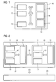
- FIG. 1 shows a multiprocessor system 10 with a plurality of processors, namely a first and second work processor 11, 12.
- the multiprocessor system includes 10 shows another processor, namely a diagnostic processor 13.
- the processors 11, 12, 13 have access to a memory 14 of the multiprocessor system 10.
- This memory 14 is in the form of individual storage areas 15, 16, 17, namely a first main memory area 15, a second Memory area 16 and a diagnostic processor memory area 17, organized.
- Each processor 11 to 13 Thus, a separate memory area 15 to 17 is assigned.
- the multiprocessor system 10 may also be one of the Number of processors 11 to 13 matched number of separate Memory include.
- the communicative connection allows at least communication between the two working processors 11, 12, z. B. for the purpose of data exchange and synchronization.
- the communicative connection enables communication from the diagnosis processor 13 to each working processor 11, 12, z. B. information about its status, in particular So a possible error situation, to receive.
- the communicative connection for each processor 11 to 13 have access to its respective assigned Memory range 15 to 17.
- the diagnostic processor 13 has due to the communicative Connection to the memory 14 Access to the memory areas 15, 16 of the working processors 11, 12 and on the own memory area, the diagnostic processor memory area 17th
- FIG 2 shows that in its graph for reasons clarity reduced multiprocessor system 10 from 1, which together with another, functional the multiprocessor system 10 corresponding multiprocessor system 20 a redundant multiprocessor system 21 forms.
- Both multiprocessor systems 10, 20 are one through a Block arrow only indicated redundancy coupling 22 communicative connected.
- This redundancy coupling 22 is the guarantee the redundancy and the associated high availability of the overall system, the redundant multiprocessor system 21, required data exchange in per se handled in a known manner.
- z. B. each about a central unit of a programmable logic Control with at least two working processors 11, 12 and a diagnostic processor 13.
- the redundant multiprocessor system 21 then z. B. by the interconnection two such central units, which is due to the usual modular design of these devices and the connectivity a system bus is easily possible.
- Such a redundant Multiprocessor system 21 is preferred for control and / or Monitoring of technical processes used, being considered technical Process basically any automatable technical Process 23, so z. B. Production processes for production of goods and merchandise, chemical processes, energy production, Waste treatment and recycling, etc., into consideration comes.
- the respectively controlled or supervised technical Process 23 is also shown only stylized accordingly.
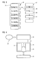
- each Multiprocessor system 10 Every working processor 11, 12 of each multiprocessor system 10, 20 introduces his memory area 15, 16 stored control program 25, 26, which in FIG 3 by a simple Flowchart is shown.
- the diagnostic processor 13 each Multiprocessor system 10, 20 carries its own control program, a diagnostic program 27, located in the diagnostic processor memory area 17 is stored.
- the diagnostic program 27 is for monitoring in the same multiprocessor system 10, 20 existing work processors 11, 12 intended. Therefore, the diagnostic program 27 contains a first one Sequence of instructions 28, with which, so to speak, in an infinite loop 29 a monitoring of the respective work processors 11, 12 takes place.
- This endless loop 29 is interrupted only if for at least one of the working processors 11, 12 by means of the instructions 28 an error situation, eg. B. a Absence of a "sign of life" was detected. Then it will be with first further instructions 30, which are part of the Diagnostic program 27 are a backup of the system health of the respective work processors. To secure the system state is provided in particular that both Work processors are stopped during the backup.
- the system state is a data set or a data sequence, the current status of a working processor 11, 12 represents. It preferably comprises the entire so-called Processor context, ie the contents of the processor-own Register, and possibly the contents of the working processor 11, 12 associated data memory or predetermined or specifiable excerpts thereof.
- Processor context ie the contents of the processor-own Register
- working processor 11, 12 associated data memory or predetermined or specifiable excerpts thereof.
- data storage is while a part of the working memory area 15, 16 understood, in particular the part of the working memory area 15, 16, the not for storing the respective control program 25, 26 is used and therefore only contains data that the control program 25, 26 processed or processed during operation.
- Second further instructions 31 for that of the error situation unaffected multiprocessor system 10, 20 is a Troubleshooting mode activated, either as a separately callable Subroutine on the respective work processor 11, 12 or as a separately invoked subroutine on the Diagnostic processor 13 can be realized.
- the troubleshooting operation provides at least one piece of information as a result going on, as the cause of the error situation, a hardware error comes into consideration. If such a hardware error as Result of the debugging operation is excluded, that of the error situation affected multiprocessor system 10, 20th restarted.
- This reboot can also be part of it of the troubleshooting operation, must not be necessary in Be implemented under the second additional instructions 31.
- After processing the second further instructions 31 branches the diagnostic program 27 again for continuous Monitoring of the working processors 11, 12.
- the secured system state is in the diagnostic processor memory area 17 filed. According to an advantageous embodiment can be provided that the secured system state or a message about the error situation and the Loss of high availability via a data line 32 at one at a central location in the technical process 23, for example a control room, arranged control room computer 33 is transmitted. This is shown in FIG. From here can be off either automatically or by user intervention further action is taken. If the control room computer 33 has access to the Internet 34, the as System state backed up data also to external service providers, for example, the supplier of the control hardware, in particular the redundant multiprocessor system 21, or the supplier of the control programs 25, 26, to analyze the error situation.
- external service providers for example, the supplier of the control hardware, in particular the redundant multiprocessor system 21, or the supplier of the control programs 25, 26, to analyze the error situation.
- a multiprocessor system 10, 20 indicated in addition a plurality of working processors 11, 12 at least one Diagnostic processor 13, which is used to monitor the working processors 11, 12 and in case of error to secure a System state either each work processor 11, 12 or the multiprocessor system 10, 20 is provided. If two or more such multiprocessor systems 10, 20 into one redundant multiprocessor system 21 are combined, For example, each diagnostic processor 13 can determine the system state of its own Multiprocessor system 10, 20 secure, so that in case of failure a system state of the overall system, namely of the redundant multiprocessor system 21, for a later Evaluation is available. The actual backup of the System state requires little time and is always possible since it is assumed that the diagnostic processor 13 of the respective error situation is not affected. After Backup can all work processors 11, 12 or all involved systems 10, 20 resume operation. The Analysis of the data obtained during the backup can offline, So without further operational degradation, done.
Landscapes
- Engineering & Computer Science (AREA)
- Theoretical Computer Science (AREA)
- Quality & Reliability (AREA)
- Physics & Mathematics (AREA)
- General Engineering & Computer Science (AREA)
- General Physics & Mathematics (AREA)
- Hardware Redundancy (AREA)
Abstract
Es wird ein Multiprozessorsystem (10,20) und ein Verfahren zu dessen Betrieb angegeben, wobei neben einer Mehrzahl von Arbeitsprozessoren (11,12) zumindest ein Diagnoseprozessor (13) vorgesehen ist. Diesen überwacht die Arbeitsprozessoren (11,12) und sichert im Fehlerfall einen Systemzustand entweder jedes Arbeitsprozessors (11,12) oder des Multiprozessorsystems (10,20). Weiterhin wird ein redundantes Multiprozessorsystem angegeben, bestehend aus zwei durch eine Redundanzkopplung verbundenen Multiprozessorsystemen, welche jeweils den oben beschriebenen Diagnoseprozessor beinhalten. <IMAGE>
Description
Die Erfindung betrifft ein Verfahren zum Betrieb eines Mehr-
oder Multiprozessorsystems. Die Erfindung betrifft darüber
hinaus auch das nach dem Verfahren arbeitende Mehr- oder
Multiprozessorsystem selbst. Die Erfindung bezieht sich vorzugsweise
auf ein Multiprozessorsystem oder ein Verfahren zum
Betrieb eines solchen Multiprozessorsystems, das zur Anwendung
im Bereich der Automatisierung technischer Prozesse vorgesehen
ist. Das Multiprozessorsystem ist dann als Automatisierungsgerät
realisiert oder zumindest Bestandteil eines
Automatisierungsgerätes.
Ein Mehr- oder Multiprozessorsystem zeichnet sich im Gegensatz
zu einem Einzelprozessorsystem durch eine Mehrzahl von
Verarbeitungseinheiten, also Prozessoren, ASICs oder dergleichen,
im Folgenden zusammenfassend als Arbeitsprozessoren
bezeichnet, aus. Die einzelnen Arbeitsprozessoren verarbeiten
gleichzeitig einzelne unabhängige Steuerungsprogramme oder
unabhängige Teile eines einzelnen Steuerungsprogramms, im
Folgenden zusammenfassend ebenfalls als Steuerungsprogramm
bezeichnet. Bei der Anwendung des Multiprozessorsystems zur
Automatisierung technischer Prozesse handelt es sich bei dem
oder jedem solchen Steuerungsprogramm um ein Programm, das
zur Be- und Verarbeitung von Daten aus dem technischen Prozess
und zur Ausgabe von Steuerungsbefehlen an den technischen
Prozess, etwa zum Ein- oder Ausschalten einzelner Geräte,
vorgesehen ist.
Das oder jedes Steuerungsprogramm ist in einem dem jeweiligen
Arbeitsprozessor zugeordneten Arbeitsspeicherbereich abgelegt.
Falls bei einem der Arbeitsprozessoren ein Fehler, insbesondere
ein Fehler beim Abarbeiten des jeweiligen Steuerungsprogramms,
auftritt, der zu einem Systemstillstand führt,
bleibt entweder das gesamte Multiprozessorsystem oder zumindest
der von dem Fehler betroffene Arbeitsprozessor für
Diagnosezwecke stehen, so dass in jedem Fall die Funktion des
Gesamtsystems betroffen ist.
Eine Wiederaufnahme der Funktion ist erst nach Analyse des
Fehlers sowie einem ggf. manuell auszulösenden Systemneustart
(Wiederanlauf) möglich. Dadurch wird die Verfügbarkeit des
Gesamtsystems deutlich verringert.
Zur Behandlung einer solchen Fehlersituation sind bisher zwei
Verfahren mit jeweils spezifischen Nachteilen bekannt geworden.
Nach einem der Verfahren ist vorgesehen, dass das Multiprozessorsystem
im Fehlerfall in eine Endlosschleife verzweigt
und den Systemzustand damit quasi einfriert, da in der
Endlosschleife keine Veränderungen an den Daten, die zu dem
Fehler geführt haben, z. B. wesentlichen Daten des Prozessorkontexts
und dem Inhalt des oder jedes Arbeitsspeichers, vorgenommen
werden. Der auf diese Weise konservierte Systemzustand
kann zu einem späteren Zeitpunkt analysiert werden,
um die Ursache für die Fehlersituation zu ermitteln.
Ein weiterer Betrieb des Multiprozessorsystems, also auch der
von der Fehlersituation nicht direkt betroffenen Arbeitsprozessoren,
ist nicht möglich. Das "Einfrieren" des gesamten
Systems ist erforderlich, weil Aktionen oder das Ausbleiben
von Aktionen eines Arbeitsprozessors den Stillstand anderer
Arbeitsprozessoren zur Folge haben können. Nach Beseitigung
der Fehlersituation ist ein ggf. manuell auszulösender Neustart
erforderlich. Während der Zeit zwischen Eintreten der
Fehlersituation und Neustart ist das Multiprozessorsystem
nicht verfügbar, so dass auch ein gesteuerter und/oder überwachter
technischer Prozess während dieser Zeit unterbrochen
ist.
Gemäß dem anderen Verfahren ist zur Erhöhung der Verfügbarkeit
des Multiprozessorsystems vorgesehen, dass das System im
Fehlerfall selbständig einen Neustart (booten) auslösen kann,
um möglichst rasch den Produktivbetrieb wieder aufzunehmen.
Die Verfügbarkeit des Multiprozessorsystems wird dabei zwar
in gewünschter Weise erhöht, aber es gehen die Daten, die vor
Eintreten der Fehlersituation vorgelegen haben und die voraussichtlich
die Fehlersituation herbeigeführt haben, verloren,
so dass eine spätere Analyse der Ursache der Fehlersituation
unmöglich ist.
Bei speziellen Anwendungsfällen wird ein Steuerungssystem,
also eine Kombination von Automatisierungsgeräten, zur Vermeidung
von kritischen Situationen im gesteuerten und/oder
überwachten technischen Prozess häufig redundant ausgeführt.
Auch Multiprozessorsysteme können mit zwei oder mehr einzelnen
Multiprozessorsystemen redundant ausgeführt sein. Ein
Gesamtsystem mit redundanten Einzelsystemen oder Einzelgeräten
wird als hochverfügbares System bezeichnet. Bei einer
Fehlersituation in einem der Systeme übernimmt das redundante
System die Aufgaben des ausgefallenen Systems. Das ausgefallene
System kann hinsichtlich seiner Daten "eingefroren"
werden, so dass diese für eine spätere Analyse der Ursache
der Fehlersituation zur Verfügung stehen. Während des Stillstands
des ausgefallenen Systems ist allerdings die eigentlich
beabsichtigte Hochverfügbarkeit nicht gegeben. Des
Weiteren kann in einer Fehlersituation der Systemzustand des
fehlerfreien Systems nicht gesichert werden, der eventuell
zur Analyse der Ursache der Fehlersituation ebenfalls wichtig
ist.
Der Erfindung liegt die Aufgabe zugrunde, ein Multiprozessorsystem
sowie ein Verfahren zu dessen Betrieb anzugeben, mit
dem sich einzelne oder alle oben genannten Nachteile vermeiden
oder hinsichtlich ihrer Auswirkungen zumindest reduzieren
lassen.
Diese Aufgabe wird erfindungsgemäß mit den Merkmalen des
Anspruchs 1 gelöst. Dazu ist bei einem Multiprozessorsystem
mit mindestens einem ersten und einem zweiten Arbeitsprozessor
vorgesehen, dass mit dem Multiprozessorsystem
mindestens ein Diagnoseprozessor kommunikativ verbunden ist,
wobei der Diagnoseprozessor zur Sicherung des Systemzustands
des Multiprozessorsystems geeignet und vorgesehen ist. Bei
einem solchen Multiprozessorsystem handelt es sich bevorzugt
um das Multiprozessorsystem eines Automatisierungsgerätes,
also z. B. um eine Zentraleinheit einer speicherprogrammierbaren
Steuerung, um einen zum Einsatz in Industrieumgebungen
vorgesehenen Industrierechner oder dergleichen. Der oder
jeder eigentliche Arbeitsprozessor wird also von Vorgängen im
Zusammenhang mit einer evtl. Diagnose vollständig oder zumindest
nahezu vollständig entlastet.
Die oben genannte Aufgabe wird entsprechend auch mit einem
korrespondierenden Verfahren gelöst. Dazu ist bei einem Verfahren
zum Betrieb eines Multiprozessorsystems der oben genannten
Art vorgesehen, dass das Multiprozessorsystem kommunikativ
mit einem Diagnoseprozessor verbunden ist und dass
der Diagnoseprozessor bei einem Fehler des Multiprozessorsystems
den Systemzustand des Multiprozessorsystems sichert.
Die Erfindung geht von der Erkenntnis aus, dass nur ein
zusätzlicher Prozessor, nämlich der Diagnoseprozessor, der
exklusiv für die Behandlung von Aufgaben im Zusammenhang mit
der Diagnose des jeweiligen Multiprozessorsystems vorgesehen
ist, geeignet ist, sämtliche denkbaren Fehlersituationen zu
handhaben. Der Diagnoseprozessor läuft unabhängig von den
Arbeitsprozessoren und ist daher zu jedem Zeitpunkt in der
Lage, diese zu überwachen. Bei einer Fehlersituation bei
einem oder mehreren Arbeitsprozessoren kann der Diagnoseprozessor
vorgegebene oder vorgebbare Maßnahmen einleiten.
Eine Fehlersituation erkennt der Diagnoseprozessor aufgrund
der kommunikativen Verbindung mit dem jeweiligen Multiprozessorsystem.
So kann z. B. vorgesehen sein, dass das
Multiprozessorsystem eine Art "Lebenszeichen" abgibt, indem
z. B. kontinuierlich der Inhalt einer bestimmten Speicherstelle
umgeschaltet wird. Der Diagnoseprozessor überwacht ein
solches Lebenszeichen und leitet bei Ausbleiben des Lebenszeichens
sofort die jeweils vorgesehenen Maßnahmen ein.
Der Vorteil der Erfindung besteht in der entkoppelten Struktur
des Gesamtsystems, nämlich der Arbeitsprozessoren einerseits
und des Diagnoseprozessors andererseits, bei der ein
Fehler bei einem oder mehreren Arbeitsprozessoren die Funktion
des Diagnoseprozessors nicht betrifft, so dass dieser
die zur Diagnose der Fehlersituation benötigten Daten, also
den Systemzustand des Multiprozessorsystems, beschaffen kann,
während dieses angehalten (eingefroren) ist. Diese Diagnosedaten
stehen dann für eine spätere Auswertung zur Verfügung.
Die abhängigen Ansprüche sind auf bevorzugte Ausführungsformen
der vorliegenden Erfindung gerichtet.
Bevorzugt ist zur kommunikativen Verbindung von Multiprozessorsystem
und Diagnoseprozessor der Diagnoseprozessor
mit jedem Arbeitsprozessor kommunikativ verbunden, so dass
der Diagnoseprozessor auf die einzelnen Arbeitsprozessoren
und speziell den diesen jeweils zugeordneten Arbeitsspeicher
direkt zugreifen kann. Dies ist bei einer Fehlersituation,
die nicht nur einzelne oder mehrere Arbeitsprozessoren, sondern
auch etwaige Peripherie betrifft, die einzige Möglichkeit,
bei der der Diagnoseprozessor immer noch auf die Arbeitsprozessoren
Zugriff hat.
Bevorzugt umfasst die Sicherung des Systemzustands des Multiprozessorsystems
eine Sicherung des Prozessorkontexts jedes
Arbeitsprozessors. Der Prozessorkontext umfasst alle Informationen,
also insbesondere Inhalte der prozessoreigenen Register,
die das Verhalten und die Arbeitsweise des Arbeitsprozessors
im Zeitpunkt des Auftretens der Fehlersituation
beeinflussen. Durch das Wiederherstellen des gesicherten
Prozessorkontexts zu einem späteren Zeitpunkt kann die Situation,
die bei Eintreten des Fehlers vorgelegen hat, für
Diagnosezwecke wieder hergestellt werden. Optional umfasst
die Sicherung des Systemzustands des Multiprozessorsystems
auch eine Sicherung des Inhalts des Arbeitsspeichers des
betroffenen oder sämtlicher Arbeitsprozessoren. Auf diese
Weise kann zu einem späteren Zeitpunkt eine Fehlersituation
erkannt werden, die aufgrund der Verarbeitung fehlerhafter
Daten, nämlich Inhalten des Arbeitsspeichers, eingetreten
ist, z. B. durch das Ziehen einer Wurzel aus einer negativen
Zahl oder dergleichen.
Wenn mit einem ersten und einem zweiten Multiprozessorsystem
der oben genannten Art ein redundantes Multiprozessorsystem
gebildet wird, sind beide Multiprozessorsysteme bevorzugt
mittels einer Redundanzkopplung kommunikativ verbunden, so
dass sie untereinander Daten austauschen können, die zur
gegenseitigen Synchronisation erforderlich sind und die damit
den eigentlichen Redundanzbetrieb, also die jederzeitige Möglichkeit,
dass eines der Multiprozessorsysteme die Aufgaben
des anderen, ausgefallenen Multiprozessorsystems übernimmt,
erst ermöglichen. Ein solcher Redundanzbetrieb ist besonders
bei der Steuerung und/oder Überwachung (kritischer) technischer
Prozesse, z. B. chemischer Prozesse, von besonderem
Interesse, so dass solche redundanten Multiprozessorsysteme
besonders bevorzugt in Form eines redundanten Automatisierungsgerätes
mit einem ersten und einem zweiten solchen
Multiprozessorsystem ausgeführt werden.
Wenn der Systemzustand oder der oder jeder Prozessorkontext
des jeweiligen Multiprozessorsystems durch einen Zugriff auf
den jeweiligen Diagnoseprozessor auslesbar ist, können die
vom Diagnoseprozessor gesicherten Daten auch an einem entfernten
Ort zwischengespeichert und/oder analysiert werden.
Als entfernter Ort kommt dabei z. B. eine Leitwarte mit einem
Leitwartenrechner, also eine dem Multiprozessorsystem hierarchisch
übergeordnete Einheit, in Betracht. Von dieser Leitwarte
aus können auch automatisch oder durch einen Benutzereingriff
Maßnahmen zur Beseitigung der Fehlersituation eingeleitet
werden. Schließlich ist möglich, dass mittels des
Leitwartenrechners die vom Diagnoserechner aufgenommenen
Daten an ein weiteres redundantes Multiprozessorsystem übertragen
werden, das das fehlerhafte Multiprozessorsystem nachbildet,
aber nicht mit dem technischen Prozess verbunden ist,
so dass erweiterte Möglichkeiten zur Fehlersuche, etwa auch
durch einen Programmierer, genutzt werden können. Das weitere
redundante Multiprozessorsystem muss sich nicht notwendig am
Ort der Leitwarte oder des fehlerhaften Multiprozessorsystems
befinden, sondern kann auch in den Räumen eines Automatisierungsdienstleisters
aufgebaut sein, wobei die Übermittlung
der vom Diagnoserechner gesammelten Daten per Datenfernübertragung,
z. B. über Internet, erfolgt.
Bei einer Fehlersituation bei mindestens einem der Arbeitsprozessoren
des redundanten Multiprozessorsystems ist bevorzugt
als Verfahren zu dessen Betrieb vorgesehen, dass bei
einem Fehler in einem der Multiprozessorsysteme, also dem
fehlerhaften Multiprozessorsystem, dessen Diagnoseprozessor
den Systemzustand sichert und dann einen Fehlersuchbetrieb
aktiviert, wobei das fehlerhafte Multiprozessorsystem neu
gestartet wird, wenn im Fehlersuchbetrieb kein Hardwarefehler
erkannt wurde. Dieses Verfahren gewährleistet, dass das
fehlerhafte Multiprozessorsystem möglichst schnell nach Eintritt
der Fehlersituation wieder in Betrieb geht, so dass der
Redundanzbetrieb und damit die Hochverfügbarkeit nur kurz
unterbrochen ist. Es hat sich nämlich gezeigt, dass nach
einem Neustart häufig ungünstige Konstellationen, die zu
einer Fehlersituation führen können, beseitigt sind, sofern
nicht ein Hardwarefehler zu der Fehlersituation geführt hat.
Dies wird im Fehlersuchbetrieb aber überprüft, so dass der
Neustart nur dann erfolgt, wenn Aussicht besteht, dass die
Fehlersituation durch den Neustart beseitigt ist.
Das soeben beschriebene Verfahren kann vorteilhaft dahin
gehend ergänzt sein, dass nicht nur der Diagnoseprozessor des
fehlerhaften Multiprozessorsystems den jeweiligen Systemzustand
sichert, sondern dass alle Diagnoseprozessoren den
jeweiligen Systemzustand sichern. Auf diese Weise wird der
Systemzustand des redundanten Gesamtsystems aufgezeichnet, so
dass zu einem späteren Zeitpunkt auch Fehlersituationen erkannt
und untersucht werden können, die sich nur aufgrund
einer besonderen, beide redundanten Multiprozessorsysteme
wechselseitig beeinflussenden Konstellation ergeben haben.
Für den Fall eines automatisch auslösbaren Neustarts des
fehlerhaften Multiprozessorsystems ist bevorzugt vorgesehen,
dass sich das fehlerhafte Multiprozessorsystem nach einem
solchen Neustart über die Redundanzkopplung mit dem anderen,
als dem fehlerfreien Multiprozessorsystem synchronisiert und
damit den Redundanzbetrieb wieder aufnimmt.
Zur Signalisierung des Redundanzverlusts, also des Zustands,
bei dem keine Hochverfügbarkeit gegeben ist, ist vorgesehen,
dass das fehlerfreie Multiprozessorsystem eine Meldung über
den Redundanzverlust an eine übergeordnete Einheit, insbesondere
einen Leitwartenrechner, absetzt. Dies kann über den
Diagnoseprozessor des fehlerfreien Multiprozessorsystems
erfolgen. Alternativ ist auch denkbar, dass der Diagnoseprozessor
des fehlerhaften Multiprozessorsystems eine solche
Meldung absetzt. Gemäß einer weiteren günstigen Ausgestaltung
ist vorgesehen, dass eine solche Meldung nur abgesetzt wird,
wenn die Dauer des Redundanzverlusts eine vorgegebene oder
vorgebbare Zeitspanne übersteigt. Eine solche Meldung kann
nämlich unnötig sein, wenn nach einem Neustart des fehlerhaften
Multiprozessorsystems der Redundanzbetrieb unmittelbar
wieder aufgenommen werden kann. Der Nutzen einer solchen
Meldung ist evident. Aufgrund einer solchen Meldung wird ggf.
Servicepersonal zur Wartung des redundanten Multiprozessorsystems
veranlasst. Alternativ ist auch möglich, dass der
jeweils überwachte oder gesteuerte technische Prozess bei
Redundanzverlust in einen sicheren Zustand überführt wird.
Um solche Maßnahmen oder erweiterten Eingriffs- und Beeinflussungsmöglichkeiten
bewirken zu können, ist vorgesehen,
dass der Leitwartenrechner über eine kommunikative Verbindung
zum redundanten Multiprozessorsystem auf den oder jeden
Diagnoseprozessor zugreifen kann, um den Systemzustand des
oder jedes Multiprozessorsystems auszulesen.
Nachfolgend wird ein Ausführungsbeispiel der Erfindung anhand
der Zeichnung näher erläutert. Einander entsprechende Gegenstände
der Elemente sind in allen Figuren mit den gleichen
Bezugszeichen versehen.
Darin zeigen:
- FIG 1
- ein Multiprozessorsystem,
- FIG 2
- ein redundantes Multiprozessorsystem,
- FIG 3
- eine schematische Darstellung der durch die einzelnen Prozessoren des Multiprozessorsystems ausgeführten Programme und
- FIG 4
- einen Leitwartenrechner als dem redundanten Multiprozessorsystem hierarchisch übergeordnete Einheit zusammen mit dem redundanten Multiprozessorsystem.
FIG 1 zeigt ein Multiprozessorsystem 10 mit einer Mehrzahl
von Prozessoren, nämlich einem ersten und zweiten Arbeitsprozessor
11, 12. Darüber hinaus umfasst das Multiprozessorsystem
10 einen weiteren Prozessor, nämlich einen Diagnoseprozessor
13. Die Prozessoren 11, 12, 13 haben Zugriff auf
einen Speicher 14 des Multiprozessorsystems 10. Dieser Speicher
14 ist in Form einzelner Speicherbereiche 15, 16, 17,
nämlich einem ersten Arbeitsspeicherbereich 15, einem zweiten
Arbeitsspeicherbereich 16 sowie einem Diagnoseprozessorspeicherbereich
17, organisiert. Jedem Prozessor 11 bis 13
ist also ein eigener Speicherbereich 15 bis 17 zugeordnet.
Anstelle eines Speichers 14 mit einer auf die Anzahl der
Prozessoren 11 bis 13 abgestimmten Anzahl Speicherbereiche 15
bis 17 kann das Multiprozessorsystem 10 auch eine auf die
Anzahl der Prozessoren 11 bis 13 abgestimmte Anzahl separater
Speicher umfassen.
Wie durch die Blockpfeile dargestellt, besteht zwischen den
Prozessoren 11 bis 13 untereinander und den Prozessoren 11
bis 13 und dem Speicher 14 eine kommunikative Verbindung. Die
kommunikative Verbindung ermöglicht zumindest eine Kommunikation
zwischen den beiden Arbeitsprozessoren 11, 12, z. B.
zum Zwecke des Datenaustausches und zur Synchronisation. Des
Weiteren ermöglicht die kommunikative Verbindung eine Kommunikation
vom Diagnoseprozessor 13 mit jedem Arbeitsprozessor
11, 12, um z. B. Aufschluss über dessen Status, insbesondere
also eine evtl. Fehlersituation, zu erhalten. Schließlich
ermöglicht die kommunikative Verbindung für jeden Prozessor
11 bis 13 einen Zugriff auf den ihm jeweils zugeordneten
Speicherbereich 15 bis 17. Darüber hinaus kann auch vorgesehen
sein, dass jeder Arbeitsprozessor 11, 12 neben seinem
eigenen Speicherbereich 15, 16 auch auf den Speicherbereich
15, 16 des jeweils anderen Arbeitsprozessors 11, 12 zugreifen
kann. Der Diagnoseprozessor 13 hat aufgrund der kommunikativen
Verbindung zum Speicher 14 Zugriff auf die Speicherbereiche
15, 16 der Arbeitsprozessoren 11, 12 und auf den
eigenen Speicherbereich, den Diagnoseprozessorspeicherbereich
17.
FIG 2 zeigt das in seiner graphischen Darstellung aus Gründen
der Übersichtlichkeit reduzierte Multiprozessorsystem 10 aus
FIG 1, das zusammen mit einem weiteren, funktional dem Multiprozessorsystem
10 entsprechenden Multiprozessorsystem 20 ein
redundantes Multiprozessorsystem 21 bildet.
Beide Multiprozessorsysteme 10, 20 sind über eine durch einen
Blockpfeil nur angedeutete Redundanzkopplung 22 kommunikativ
verbunden. Über diese Redundanzkopplung 22 wird der zur Gewährleistung
der Redundanz und der damit einhergehenden Hochverfügbarkeit
des Gesamtsystems, des redundanten Multiprozessorsystems
21, erforderliche Datenaustausch in an sich
bekannter Weise abgewickelt.
Bei den Multiprozessorsystemen 10, 20 handelt es sich z. B.
jeweils um eine Zentraleinheit einer speicherprogrammierbaren
Steuerung mit mindestens zwei Arbeitsprozessoren 11, 12 und
einem Diagnoseprozessor 13. Das redundante Multiprozessorsystem
21 ergibt sich dann z. B. durch die Zusammenschaltung
zweier solcher Zentraleinheiten, was aufgrund der üblichen
modularen Bauweise dieser Geräte und der Anschließbarkeit an
einen Systembus leicht möglich ist. Ein solches redundantes
Multiprozessorsystem 21 wird bevorzugt zur Steuerung und/oder
Überwachung technischer Prozesse eingesetzt, wobei als technischer
Prozess grundsätzlich jeder automatisierbare technische
Prozess 23, also z. B. Produktionsprozesse zur Herstellung
von Waren und Gütern, chemische Prozesse, Energieerzeugung,
Abfallbehandlung und -verwertung, etc., in Betracht
kommt. Der jeweils gesteuerte oder überwachte technische
Prozess 23 ist entsprechend auch nur stilisiert dargestellt.
FIG 3 zeigt eine schematische Darstellung zur Verdeutlichung
der Grundzüge des Betriebsverfahrens des redundanten Multiprozessorsystems
21 gemäß der Erfindung. Jeder Arbeitsprozessor
11, 12 jedes Multiprozessorsystems 10, 20 führt ein in
seinem Arbeitsspeicherbereich 15, 16 gespeichertes Steuerungsprogramm
25, 26 aus, das in FIG 3 durch ein einfaches
Flussdiagramm dargestellt ist. Der Diagnoseprozessor 13 jedes
Multiprozessorsystems 10, 20 führt ein eigenes Steuerungsprogramm,
ein Diagnoseprogramm 27, aus, das im Diagnoseprozessorspeicherbereich
17 gespeichert ist. Das Diagnoseprogramm
27 ist zur Überwachung der im gleichen Multiprozessorsystem
10, 20 vorhandenen Arbeitsprozessoren 11, 12
vorgesehen. Darum enthält das Diagnoseprogramm 27 eine erste
Folge von Anweisungen 28, mit denen quasi in einer Endlosschleife
29 eine Überwachung der jeweiligen Arbeitsprozessoren
11, 12 erfolgt. Diese Endlosschleife 29 wird nur unterbrochen,
wenn für zumindest einen der Arbeitsprozessoren 11,
12 mittels der Anweisungen 28 eine Fehlersituation, z. B. ein
Ausbleiben eines "Lebenszeichens", erkannt wurde. Dann wird
mit ersten weiteren Anweisungen 30, die Bestandteil des
Diagnoseprogramms 27 sind, eine Sicherung des Systemzustands
der jeweiligen Arbeitsprozessoren veranlasst. Zur Sicherung
des Systemzustands ist insbesondere vorgesehen, dass beide
Arbeitsprozessoren während der Sicherung angehalten werden.
Der Systemzustand ist dabei ein Datensatz oder eine Datenfolge,
die den momentanen Status eines Arbeitsprozessors 11,
12 darstellt. Er umfasst vorzugsweise den gesamten so genannten
Prozessorkontext, also die Inhalte der prozessoreigenen
Register, sowie ggf. den Inhalt des dem Arbeitsprozessor
11, 12 zugeordneten Datenspeichers oder vorgegebene
oder vorgebbare Ausschnitte davon. Als Datenspeicher wird
dabei ein Teil des Arbeitsspeicherbereichs 15, 16 verstanden,
insbesondere der Teil des Arbeitsspeicherbereichs 15, 16, der
nicht zur Speicherung des jeweiligen Steuerungsprogramms 25,
26 verwendet wird und darum nur Daten enthält, die das Steuerungsprogramm
25, 26 im laufenden Betrieb be- oder verarbeitet.
Im Anschluss an die Sicherung des Systemzustands wird mit
zweiten weiteren Anweisungen 31 für das von der Fehlersituation
nicht betroffene Multiprozessorsystem 10, 20 die
Fortsetzung des Betriebs veranlasst. Für das von der Fehlersituation
betroffene Multiprozessorsystem 10, 20 wird ein
Fehlersuchbetrieb aktiviert, der entweder als separat aufrufbares
Unterprogramm auf dem jeweiligen Arbeitsprozessor
11, 12 oder als separat aufrufbares Unterprogramm auf dem
Diagnoseprozessor 13 realisiert sein kann. Der Fehlersuchbetrieb
liefert als Ergebnis zumindest eine Information dahin
gehend, ob als Ursache für die Fehlersituation ein Hardwarefehler
in Betracht kommt. Wird ein solcher Hardwarefehler als
Ergebnis des Fehlersuchbetriebs ausgeschlossen, wird das von
der Fehlersituation betroffene Multiprozessorsystem 10, 20
neu gestartet. Dieser Neustart (booten) kann auch Bestandteil
des Fehlersuchbetriebs sein, muss also nicht notwendig im
Rahmen der zweiten weiteren Anweisungen 31 realisiert sein.
Nach Abarbeitung der zweiten weiteren Anweisungen 31 verzweigt
das Diagnoseprogramm 27 wieder zur kontinuierlichen
Überwachung der Arbeitsprozessoren 11, 12.
Wenn bei einer Fehlersituation nicht nur die Sicherung des
Systemzustands des von der Fehlersituation betroffenen Multiprozessorsystems
10, 20, sondern auch der Systemzustand des
komplementären Multiprozessorsystems 10, 20 gesichert werden
soll, tauschen die auf beiden Multiprozessorsystemen 10, 20
durch den jeweiligen Diagnoseprozessor 13 ausgeführten Diagnoseprogramme
27 über die Redundanzkopplung 22 in dieser
Hinsicht Daten aus, um auch bei dem nicht von der Fehlersituation
betroffenen Multiprozessorsystem 10, 20 die gewünschte
Sicherung des Systemzustands mit zeitweiligem Anhalten
der jeweiligen Arbeitsprozessoren 11, 12 während
dieser Sicherung zu veranlassen.
Der gesicherte Systemzustand wird im Diagnoseprozessorspeicherbereich
17 abgelegt. Gemäß einer vorteilhaften Ausgestaltung
kann vorgesehen sein, dass der gesicherte Systemzustand
oder eine Meldung über die Fehlersituation und den
Verlust der Hochverfügbarkeit über eine Datenleitung 32 an
einen an zentraler Stelle im technischen Prozess 23, beispielsweise
einer Leitwarte, angeordneten Leitwartenrechner
33 übermittelt wird. Dies ist in FIG 4 dargestellt. Von hier
aus können entweder automatisch oder durch Benutzereingriff
weitere Maßnahmen veranlasst werden. Wenn der Leitwartenrechner
33 Zugriff auf das Internet 34 hat, können die als
Systemzustand gesicherten Daten auch an externe Dienstleister,
beispielsweise den Lieferanten der Steuerungshardware,
also insbesondere des redundanten Multiprozessorsystems
21, oder den Lieferanten der Steuerungsprogramme 25,
26, zur Analyse der Fehlersituation übermittelt werden.
Es wird ein Multiprozessorsystem 10, 20 angegeben, das neben
einer Mehrzahl von Arbeitsprozessoren 11, 12 zumindest einen
Diagnoseprozessor 13 aufweist, der zur Überwachung der Arbeitsprozessoren
11, 12 und im Fehlerfall zur Sicherung eines
Systemzustands entweder jedes Arbeitsprozessors 11, 12 oder
des Multiprozessorsystems 10, 20 vorgesehen ist. Wenn zwei
oder mehrere solcher Multiprozessorsysteme 10, 20 zu einem
redundanten Multiprozessorsystem 21 zusammengeschlossen sind,
kann jeder Diagnoseprozessor 13 den Systemzustand des eigenen
Multiprozessorsystems 10, 20 sichern, so dass im Fehlerfall
ein Systemzustand des übergeordneten Gesamtsystems, nämlich
des redundanten Multiprozessorsystems 21, für eine spätere
Auswertung zur Verfügung steht. Die eigentliche Sicherung des
Systemzustands benötigt nur wenig Zeit und ist stets möglich,
da vorausgesetzt wird, dass der Diagnoseprozessor 13 von der
jeweiligen Fehlersituation nicht betroffen ist. Nach der
Sicherung können alle Arbeitsprozessoren 11, 12 oder alle
beteiligten Systeme 10, 20 den Betrieb wieder aufnehmen. Die
Analyse der bei der Sicherung gewonnenen Daten kann offline,
also ohne weitere Betriebsbeeinträchtigung, erfolgen.
Claims (13)
- Multiprozessorsystem (10), insbesondere Automatisierungsgerät mit einem Multiprozessorsystem (10), mit mindestens einem ersten und einem zweiten Arbeitsprozessor (11, 12), gekennzeichnet durch mindestens einen mit dem Multiprozessorsystem (10) kommunikativ verbundenen Diagnoseprozessor (13), wobei der Diagnoseprozessor (13) zur Sicherung des Systemzustands des Multiprozessorsystems (10) geeignet und vorgesehen ist.
- Multiprozessorsystem nach Anspruch 1, wobei zur kommunikativen Verbindung von Multiprozessorsystem (10) und Diagnoseprozessor (13) der Diagnoseprozessor (13) mit jedem Arbeitsprozessor (11, 12) kommunikativ verbunden ist.
- Multiprozessorsystem nach Anspruch 1 oder 2, wobei die Sicherung des Systemzustands des Multiprozessorsystems (10) eine Sicherung des Prozessorkontexts jedes Arbeitsprozessors (11, 12) umfasst.
- Verfahren zum Betrieb eines Multiprozessorsystems (10), insbesondere eines Automatisierungsgerätes mit einem Multiprozessorsystem (10), mit mindestens einem ersten und einem zweiten Arbeitsprozessor (11, 12), dadurch gekennzeichnet, dass das Multiprozessorsystem (10) kommunikativ mit einem Diagnoseprozessor (13) verbunden ist und
dass der Diagnoseprozessor (13) bei einem Fehler des Multiprozessorsystems (10) den Systemzustand des Multiprozessorsystems (10) sichert. - Verfahren zum Betrieb eines Multiprozessorsystems nach Anspruch 4, wobei die kommunikative Verbindung von Multiprozessorsystem (10) und Diagnoseprozessor (13) als kommunikative Verbindung zwischen dem Diagnoseprozessor (13) und jedem Arbeitsprozessor (11, 12) realisiert ist.
- Multiprozessorsystem nach Anspruch 3 oder 4, wobei zur Sicherung des Systemzustands des Multiprozessorsystems (10) eine Sicherung des Prozessorkontexts jedes Arbeitsprozessors (11, 12) erfolgt.
- Redundantes Multiprozessorsystem mit einem ersten und einem zweiten Multiprozessorsystem (10) jeweils nach einem der Ansprüche 1, 2 oder 3, insbesondere redundantes Automatisierungsgerät mit einem ersten und einem zweiten solchen Multiprozessorsystem (10), wobei erstes und zweites Multiprozessorsystem untereinander mittels einer Redundanzkopplung (22) kommunikativ verbunden sind.
- Redundantes Multiprozessorsystem nach Anspruch 7, wobei der Systemzustand oder der oder jeder Prozessorkontext des jeweiligen Multiprozessorsystems (10, 20) durch einen Zugriff auf den jeweiligen Diagnoseprozessor (13) auslesbar ist.
- Verfahren zum Betrieb eines redundanten Multiprozessorsystems nach Anspruch 7 oder 8, wobei bei einem Fehler in einem der Multiprozessorsysteme (10, 20) - fehlerhaftes Multiprozessorsystem (10) - dessen Diagnoseprozessor (13) den Systemzustand sichert und dann einen Fehlersuchbetrieb aktiviert, wobei das fehlerhafte Multiprozessorsystem (10) neu gestartet wird, wenn im Fehlersuchbetrieb kein Hardwarefehler erkannt wurde.
- Verfahren zum Betrieb eines redundanten Multiprozessorsystems nach Anspruch 7 oder 8, wobei bei einem Fehler in einem der Multiprozessorsysteme (10, 20) - fehlerhaftes Multiprozessorsystem (10) - der Diagnoseprozessor (13) jedes Multiprozessorsystems (10, 20) den jeweiligen Systemzustand sichert, wobei für fehlerhaftes Multiprozessorsystem (10) dann ein Fehlersuchbetrieb aktiviert wird und wobei das fehlerhafte Multiprozessorsystem (10) neu gestartet wird, wenn im Fehlersuchbetrieb kein Hardwarefehler erkannt wurde.
- Verfahren nach Anspruch 9 oder 10, wobei sich das fehlerhafte Multiprozessorsystem (10) nach dem Neustart über die Redundanzkopplung (22) mit dem anderen, fehlerfreien Multiprozessorsystem (10) synchronisiert und damit den Redundanzbetrieb wieder aufnimmt.
- Verfahren nach Anspruch 9, 10 oder 11, wobei das andere, fehlerfreie Multiprozessorsystem (10) eine Meldung über den Redundanzverlust an eine übergeordnete Einheit, insbesondere einen Leitwartenrechner (33), absetzt.
- Verfahren nach Anspruch 12, wobei der Leitwartenrechner (33) über eine kommunikative Verbindung zum redundanten Multiprozessorsystem (10) auf den oder jeden Diagnoseprozessor (13) zugreift, um den Systemzustand des oder jedes Multiprozessorsystems (10, 20) auszulesen.
Priority Applications (1)
| Application Number | Priority Date | Filing Date | Title |
|---|---|---|---|
| EP04006103A EP1577773A1 (de) | 2004-03-15 | 2004-03-15 | Multiprozessorsystem mit einem Diagnoseprozessor zur Sicherung des Systemzustands und Verfahren zum Betrieb eines Multiprozessorsystems |
Applications Claiming Priority (1)
| Application Number | Priority Date | Filing Date | Title |
|---|---|---|---|
| EP04006103A EP1577773A1 (de) | 2004-03-15 | 2004-03-15 | Multiprozessorsystem mit einem Diagnoseprozessor zur Sicherung des Systemzustands und Verfahren zum Betrieb eines Multiprozessorsystems |
Publications (1)
| Publication Number | Publication Date |
|---|---|
| EP1577773A1 true EP1577773A1 (de) | 2005-09-21 |
Family
ID=34833599
Family Applications (1)
| Application Number | Title | Priority Date | Filing Date |
|---|---|---|---|
| EP04006103A Withdrawn EP1577773A1 (de) | 2004-03-15 | 2004-03-15 | Multiprozessorsystem mit einem Diagnoseprozessor zur Sicherung des Systemzustands und Verfahren zum Betrieb eines Multiprozessorsystems |
Country Status (1)
| Country | Link |
|---|---|
| EP (1) | EP1577773A1 (de) |
Cited By (1)
| Publication number | Priority date | Publication date | Assignee | Title |
|---|---|---|---|---|
| FR3129005A1 (fr) | 2021-11-10 | 2023-05-12 | Vitesco Technologies | Procédé et dispositif de contrôle et commande d’un moteur de véhicule |
Citations (4)
| Publication number | Priority date | Publication date | Assignee | Title |
|---|---|---|---|---|
| EP0414379A2 (de) * | 1989-08-01 | 1991-02-27 | Digital Equipment Corporation | Verfahren zur Softwarefehlerbehandlung |
| EP0286856B1 (de) * | 1987-04-16 | 1993-05-19 | BBC Brown Boveri AG | Fehlertolerante Rechneranordnung |
| US5444859A (en) * | 1992-09-29 | 1995-08-22 | Amdahl Corporation | Method and apparatus for tracing multiple errors in a computer system subsequent to the first occurence and prior to the stopping of the clock in response thereto |
| WO2001016746A2 (en) * | 1999-08-31 | 2001-03-08 | Sun Microsystems, Inc. | Method and apparatus for extracting first failure and attendant operating information from computer system devices |
-
2004
- 2004-03-15 EP EP04006103A patent/EP1577773A1/de not_active Withdrawn
Patent Citations (4)
| Publication number | Priority date | Publication date | Assignee | Title |
|---|---|---|---|---|
| EP0286856B1 (de) * | 1987-04-16 | 1993-05-19 | BBC Brown Boveri AG | Fehlertolerante Rechneranordnung |
| EP0414379A2 (de) * | 1989-08-01 | 1991-02-27 | Digital Equipment Corporation | Verfahren zur Softwarefehlerbehandlung |
| US5444859A (en) * | 1992-09-29 | 1995-08-22 | Amdahl Corporation | Method and apparatus for tracing multiple errors in a computer system subsequent to the first occurence and prior to the stopping of the clock in response thereto |
| WO2001016746A2 (en) * | 1999-08-31 | 2001-03-08 | Sun Microsystems, Inc. | Method and apparatus for extracting first failure and attendant operating information from computer system devices |
Cited By (3)
| Publication number | Priority date | Publication date | Assignee | Title |
|---|---|---|---|---|
| FR3129005A1 (fr) | 2021-11-10 | 2023-05-12 | Vitesco Technologies | Procédé et dispositif de contrôle et commande d’un moteur de véhicule |
| WO2023083703A1 (fr) | 2021-11-10 | 2023-05-19 | Vitesco Technologies GmbH | Procédé et dispositif de contrôle et commande d'un moteur de véhicule |
| US20240375669A1 (en) * | 2021-11-10 | 2024-11-14 | Vitesco Technologies GmbH | Method and device for monitoring and controlling a vehicle engine |
Similar Documents
| Publication | Publication Date | Title |
|---|---|---|
| DE69228803T2 (de) | Wartungs-vorrichtung und verfahren ausgelöst durch wissenbasiertemaschine | |
| EP1297394B1 (de) | Redundantes steuerungssystem sowie steuerrechner und peripherieeinheit für ein derartiges steuerungssystem | |
| EP2657797B1 (de) | Verfahren zum Betreiben eines redundanten Automatisierungssystems | |
| EP0685086B1 (de) | Einrichtung zur automatischen erzeugung einer wissensbasis für ein diagnose-expertensystem | |
| DE4317729A1 (de) | Programmierbare Steuereinheit | |
| EP2667269B1 (de) | Verfahren zum Betreiben eines redundanten Automatisierungssystems | |
| DE3751949T2 (de) | Verfahren zum Starten eines Untersystems in einem verteilten Verarbeitungssystem | |
| DE10324380B4 (de) | Programmierbare Steuerung mit CPU und Kommunikationseinheiten sowie Verfahren zur Steuerung derselben | |
| DE68922440T2 (de) | Gerät und Verfahren zur gleichzeitigen Einreichung von Fehlerunterbrechung und Fehlerdaten zu einem Unterstützungsprozessor. | |
| EP1743225B1 (de) | Redundantes automatisierungssystem umfassend ein master- und ein stand-by-automatisierungsgerät | |
| DE19905841A1 (de) | Vorrichtung zum Verarbeiten sicherheitsrelevanter Daten | |
| DE2647367A1 (de) | Redundante prozessteueranordnung | |
| EP1577773A1 (de) | Multiprozessorsystem mit einem Diagnoseprozessor zur Sicherung des Systemzustands und Verfahren zum Betrieb eines Multiprozessorsystems | |
| DE10132313A1 (de) | Programmgesteuerte Einheit | |
| EP1239369A1 (de) | Fehlertolerante Rechneranordnung und Verfahren zum Betrieb einer derartigen Anordnung | |
| DE3238692A1 (de) | Datenuebertragungssystem | |
| EP1019808B1 (de) | Responsives system und verfahren zur digitalen signalverarbeitung sowie verfahren zum betrieb eines responsiven systems | |
| DE2108836A1 (de) | Anordnung für ein Doppelrechnersystem | |
| EP4715598A1 (de) | System und verfahren zum kompensieren von ausfällen von komponenten | |
| DE102004050905A1 (de) | Monitoring-Einheit zur Überwachung und zur automatisierten Fehlerbehebung von medizinischen Applikationen | |
| EP1195678A2 (de) | Verfahren zum Beitreiben eines Datenverarbeitungssystems mit Redundanz-Datenverarbeitungseinheit | |
| DE19805819B4 (de) | Verfahren zur Überwachung von integrierten Schaltkreisen | |
| DE10228142B4 (de) | System zur Sicherung von Softwarekomponenten und/oder Computerprogrammen | |
| DE102019109353B3 (de) | Dynamische Anomalieerkennung und -behandlung | |
| EP1379952B1 (de) | Programmgesteuerte einheit |
Legal Events
| Date | Code | Title | Description |
|---|---|---|---|
| PUAI | Public reference made under article 153(3) epc to a published international application that has entered the european phase |
Free format text: ORIGINAL CODE: 0009012 |
|
| AK | Designated contracting states |
Kind code of ref document: A1 Designated state(s): AT BE BG CH CY CZ DE DK EE ES FI FR GB GR HU IE IT LI LU MC NL PL PT RO SE SI SK TR |
|
| AX | Request for extension of the european patent |
Extension state: AL LT LV MK |
|
| AKX | Designation fees paid | ||
| STAA | Information on the status of an ep patent application or granted ep patent |
Free format text: STATUS: THE APPLICATION IS DEEMED TO BE WITHDRAWN |
|
| 18D | Application deemed to be withdrawn |
Effective date: 20060322 |
|
| REG | Reference to a national code |
Ref country code: DE Ref legal event code: 8566 |