EP1577688A1 - Chromatic dispersion-compensating optical fibre in the S-band using a higher order mode - Google Patents
Chromatic dispersion-compensating optical fibre in the S-band using a higher order mode Download PDFInfo
- Publication number
- EP1577688A1 EP1577688A1 EP05075590A EP05075590A EP1577688A1 EP 1577688 A1 EP1577688 A1 EP 1577688A1 EP 05075590 A EP05075590 A EP 05075590A EP 05075590 A EP05075590 A EP 05075590A EP 1577688 A1 EP1577688 A1 EP 1577688A1
- Authority
- EP
- European Patent Office
- Prior art keywords
- index
- dispersion
- optical fibre
- compensating optical
- wavelength
- Prior art date
- Legal status (The legal status is an assumption and is not a legal conclusion. Google has not performed a legal analysis and makes no representation as to the accuracy of the status listed.)
- Ceased
Links
Images

Classifications
-
- G—PHYSICS
- G02—OPTICS
- G02B—OPTICAL ELEMENTS, SYSTEMS OR APPARATUS
- G02B6/00—Light guides; Structural details of arrangements comprising light guides and other optical elements, e.g. couplings
- G02B6/02—Optical fibres with cladding with or without a coating
- G02B6/036—Optical fibres with cladding with or without a coating core or cladding comprising multiple layers
- G02B6/03616—Optical fibres characterised both by the number of different refractive index layers around the central core segment, i.e. around the innermost high index core layer, and their relative refractive index difference
- G02B6/03688—Optical fibres characterised both by the number of different refractive index layers around the central core segment, i.e. around the innermost high index core layer, and their relative refractive index difference having 5 or more layers
-
- G—PHYSICS
- G02—OPTICS
- G02B—OPTICAL ELEMENTS, SYSTEMS OR APPARATUS
- G02B6/00—Light guides; Structural details of arrangements comprising light guides and other optical elements, e.g. couplings
- G02B6/02—Optical fibres with cladding with or without a coating
- G02B6/02004—Optical fibres with cladding with or without a coating characterised by the core effective area or mode field radius
- G02B6/02009—Large effective area or mode field radius, e.g. to reduce nonlinear effects in single mode fibres
- G02B6/02014—Effective area greater than 60 square microns in the C band, i.e. 1530-1565 nm
-
- G—PHYSICS
- G02—OPTICS
- G02B—OPTICAL ELEMENTS, SYSTEMS OR APPARATUS
- G02B6/00—Light guides; Structural details of arrangements comprising light guides and other optical elements, e.g. couplings
- G02B6/02—Optical fibres with cladding with or without a coating
- G02B6/02004—Optical fibres with cladding with or without a coating characterised by the core effective area or mode field radius
- G02B6/02009—Large effective area or mode field radius, e.g. to reduce nonlinear effects in single mode fibres
- G02B6/02023—Based on higher order modes, i.e. propagating modes other than the LP01 or HE11 fundamental mode
-
- G—PHYSICS
- G02—OPTICS
- G02B—OPTICAL ELEMENTS, SYSTEMS OR APPARATUS
- G02B6/00—Light guides; Structural details of arrangements comprising light guides and other optical elements, e.g. couplings
- G02B6/02—Optical fibres with cladding with or without a coating
- G02B6/02047—Dual mode fibre
-
- G—PHYSICS
- G02—OPTICS
- G02B—OPTICAL ELEMENTS, SYSTEMS OR APPARATUS
- G02B6/00—Light guides; Structural details of arrangements comprising light guides and other optical elements, e.g. couplings
- G02B6/02—Optical fibres with cladding with or without a coating
- G02B6/02214—Optical fibres with cladding with or without a coating tailored to obtain the desired dispersion, e.g. dispersion shifted, dispersion flattened
- G02B6/02219—Characterised by the wavelength dispersion properties in the silica low loss window around 1550 nm, i.e. S, C, L and U bands from 1460-1675 nm
- G02B6/02252—Negative dispersion fibres at 1550 nm
- G02B6/02261—Dispersion compensating fibres, i.e. for compensating positive dispersion of other fibres
-
- H—ELECTRICITY
- H04—ELECTRIC COMMUNICATION TECHNIQUE
- H04B—TRANSMISSION
- H04B10/00—Transmission systems employing electromagnetic waves other than radio-waves, e.g. infrared, visible or ultraviolet light, or employing corpuscular radiation, e.g. quantum communication
- H04B10/25—Arrangements specific to fibre transmission
- H04B10/2507—Arrangements specific to fibre transmission for the reduction or elimination of distortion or dispersion
- H04B10/2513—Arrangements specific to fibre transmission for the reduction or elimination of distortion or dispersion due to chromatic dispersion
- H04B10/2525—Arrangements specific to fibre transmission for the reduction or elimination of distortion or dispersion due to chromatic dispersion using dispersion-compensating fibres
-
- G—PHYSICS
- G02—OPTICS
- G02B—OPTICAL ELEMENTS, SYSTEMS OR APPARATUS
- G02B6/00—Light guides; Structural details of arrangements comprising light guides and other optical elements, e.g. couplings
- G02B6/02—Optical fibres with cladding with or without a coating
- G02B6/02214—Optical fibres with cladding with or without a coating tailored to obtain the desired dispersion, e.g. dispersion shifted, dispersion flattened
- G02B6/02285—Characterised by the polarisation mode dispersion [PMD] properties, e.g. for minimising PMD
Definitions
- the invention relates to the field of chromatic dispersion-compensating optical fibres for a wavelength multiplexing transmission system.
- the function of the dispersion-compensating optical fibre is to compensate for the chromatic dispersion of a so-called line fibre.
- the invention relates more precisely to an chromatic dispersion-compensating optical fibre in the S-band for use in compensating for the chromatic dispersion of either a standard SMF optical fibre or of an NZ-DSF optical fibre, where the line optical fibre carries an optical signal in the spectral band in use, which is the S-band extending from 1460 nm to 1530 nm.
- a dispersion-compensating optical fibre for a wavelength multiplexing transmission system comprising, from the centre towards the periphery, a core having a variable index profile then a cladding of constant index, wherein, the chromatic dispersion is less than - 150 ps/nm.km, the chromatic dispersion slope is strictly negative, and the effective area is greater than 40 ⁇ m 2 .
- the difference between the wavelength corresponding to the overall minimum chromatic dispersion and the wavelength corresponding to an upper limit of an operating spectral range greater than 30 nm is greater than 35 nm, and the relative variation of the dispersion slope over said operating spectral range has an absolute value less than 30 %.
- a limited mode dispersion compensating optical fiber supporting at least one high order spatial mode comprising: a plurality of core areas, the refractive index profile of which are selected to result in an optical waveguide providing in the LP 02 mode: dispersion more negative than -300 ps/nm/km at a representative wavelength, designated ⁇ 0 , within an operative waveband; projected zero dispersion less than ( ⁇ 0 -75 nm), where projected zero dispersion is defined as ⁇ 0 -Dispersion ( ⁇ 0 )/Slope ( ⁇ 0 ); and third order dispersion less than 2 % over the operative waveband, where third order dispersion is defined as the maximum deviation from a best line fit for dispersion divided the best fit dispersion at ⁇ 0 , said best fit line chosen to minimize said maximum deviation.
- the solution proposed by the invention accordingly relates to an H0M dispersion-compensating optical fibre in the S-band exhibiting as small variations as possible in the chromatic dispersion slope in order to enable effective compensation for chromatic dispersion and for the chromatic dispersion slope across the entire S-band.
- the minimum chromatic dispersion wavelength is selected from a narrow and optimum spectral range in order to ensure a good compromise between the low level of variation in the chromatic dispersion slope in the S-band, the high value for effective area, the very negative chromatic dispersion value, and a chromatic dispersion to chromatic dispersion slope ratio that is as close as possible to that of the line optical fibre to be compensated.
- the optimum range for the minimum chromatic dispersion wavelength and the compromise between the parameters and optical properties being sought are slightly different.
- an chromatic dispersion-compensating optical fibre in the spectral band S extending from 1460 nm to 1530 nm for a wavelength multiplexing transmission system, comprising successively, from the centre to the periphery, a core having a variable index profile and then a cladding of constant index, enabling the propagation, at a wavelength of 1495 nm, in addition to the fundamental mode LP 01 , of at least one higher order mode, the index profile of the core being determined in such a manner that, for said higher mode, on the one hand at a wavelength of 1495 nm, firstly the chromatic dispersion is less than -150 ps/nm-km, secondly the chromatic dispersion to chromatic dispersion slope ratio is between 200 nm and 300 nm, and thirdly the effective area is greater than 60 ⁇ m 2 and, on the other hand, the wavelength
- the index profile of the core is determined in such a manner that, for said higher mode, at a wavelength of 1495 nm, the chromatic dispersion to chromatic dispersion slope ratio is between 200 nm and 250 nm.
- the index profile of the core is determined in such a manner that, for said higher mode, at a wavelength of 1495 nm, the wavelength corresponding to the global chromatic dispersion minimum is between 1570 nm and 1590 nm.
- the index profile of the core is determined in such a manner that, for said higher mode, at a wavelength of 1495 nm, the effective area is greater than 70 ⁇ m 2 , and preferably greater than 80 ⁇ m 2 .
- the maximum index difference ⁇ n 1 between the index of the central slice and the index of the cladding is between 20.10 -3 and 32.10 -3 and the outer radius r 1 of the central slice is between 3 ⁇ m and 4.5 ⁇ m.
- the value of the integral of the index difference relative to the cladding, between a zero radius and the radius r 1 of the portion of the central slice having an index higher than the index of the cladding is between 100.10 -3 and 115.10 -3 ⁇ m.
- the value of twice the integral of the product of the index difference relative to the cladding times the radius, between a zero radius and the radius r 1 of the portion of the central slice having an index higher than the index of the cladding is between 325.10 -3 ⁇ m 2 and 475.10 -3 ⁇ m 2 .
- the value of twice the integral of the product of the index difference relative to the cladding times the radius, between a zero radius and the radius r 3 of the second peripheral slice is between 400.10 -3 ⁇ m 2 and 800.10 -3 ⁇ m 2 .
- the index difference ⁇ n 2 between the index of the first peripheral slice and the index of the cladding is between -4.10 -3 and 5.10 -3 and the outer radius r 2 of the first peripheral slice is between 5 ⁇ m and 11 ⁇ m.
- the index difference ⁇ n 3 between the index of the second peripheral slice and the index of the cladding is between -5.10 -3 and 5.10 -3 and the outer radius r 3 of the second peripheral slice is between 8 ⁇ m and 15 ⁇ m.
- the index difference ⁇ n 4 between the index of the third peripheral slice and the index of the cladding is between -5.10 -3 and 5.10 -3 and the outer radius r 4 of the third peripheral slice is between 11 ⁇ m and 17 ⁇ m.
- the index difference ⁇ n 5 between the index of the fourth peripheral slice and the index of the cladding is between 0 and 10.10 -3 and the outer radius r 5 of the fourth peripheral slice is between 14 ⁇ m and 17 ⁇ m.
- an chromatic dispersion-compensating optical fibre in the spectral band S extending from 1460 nm to 1530 nm, for a wavelength multiplexing transmission system, comprising successively, from the centre to the periphery, a core having a variable index profile and then a cladding of constant index, enabling the propagation, at a wavelength of 1495 nm, in addition to the fundamental mode LP 01 , of at least one higher order mode, the index profile of the core being determined in such a manner that, for said higher mode, on the one hand at a wavelength of 1495 nm, firstly the chromatic dispersion is lower than -150 ps/nm-km, secondly the chromatic dispersion to chromatic dispersion slope ratio is less than 130 nm and thirdly the effective area is greater than 50 ⁇ m 2 and, on the other hand, the wavelength corresponding to the global
- the index profile of the core is determined in such a manner that, for said higher mode, at a wavelength of 1495 nm, the chromatic dispersion to chromatic dispersion slope ratio is between 90 nm and 110 nm.
- the index profile of the core is determined in such a manner that, for said higher mode, at a wavelength of 1495 nm, the wavelength corresponding to the global chromatic dispersion minimum is between 1540 nm and 1560 nm.
- the index profile of the core is determined in such a manner that, for said higher mode, at a wavelength of 1495 nm, the effective area is greater than 65 ⁇ m 2 , preferably greater than 80 ⁇ m 2 .
- the maximum index difference ⁇ n 1 between the index of the central slice and the index of the cladding is between 15.10 -3 and 30.10 -3 and the outer radius r 1 of the central slice is between 3.5 ⁇ m and 5 ⁇ m.
- the value of twice the integral of the product of the index difference relative to the cladding times the radius, between a zero radius and the radius r 1 of the portion of the central slice having an index higher than the index of the cladding is between 375.10 -3 ⁇ m 2 and 525.10 -3 ⁇ m 2 .
- the value of twice the integral of the product of the index difference relative to the cladding times the radius, between a zero radius and the radius r 3 of the second peripheral slice is between 400.10 -3 ⁇ m 2 and 700.10 -3 ⁇ m 2 .
- the index difference ⁇ n 2 between the index of the first peripheral slice and the index of the cladding is between -7.10 -3 and 5.10 -3 and the outer radius r 2 of the first peripheral slice is between 5 ⁇ m and 10 ⁇ m.
- the index difference ⁇ n 3 between the index of the second peripheral slice and the index of the cladding is between -5.10 -3 and 5.10 -3 and the outer radius r 3 of the second peripheral slice is between 7 ⁇ m and 15 ⁇ m.
- the index difference ⁇ n 4 between the index of the third peripheral slice and the index of the cladding is between -5.10 -3 and 5.10 -3 and the outer radius r 4 of the third peripheral slice is between 10 ⁇ m and 16 ⁇ m.
- the index difference ⁇ n 5 between the index of the fourth peripheral slice and the index of the cladding is between 0 and 10.10 -3 and the outer radius r 5 of the fourth peripheral slice is between 14 ⁇ m and 17 ⁇ m.
- the optical fibre preferably has the following advantageous characteristics.
- the higher order mode is the mode LP 02 , for which mode chromatic dispersion-compensating optical fibres exhibiting very negative chromatic dispersions can readily be obtained, and which mode is not very sensitive to defects in the circular geometry of the fibre, which defects are responsible for the polarisation problems.
- Other higher order modes are, however, possible, such as for example the mode LP 11 or the mode LP 03 .
- the index profile of the core is determined in such a manner that, for said higher mode, at a wavelength of 1495 nm, the chromatic dispersion is less than -200 ps/nm-km, preferably less than -250 ps/nm-km, advantageously less than -300 ps/nm-km, which makes it possible, for a given line optical fibre, to reduce the length of the compensation optical fibre to be used.
- the operational spectral band used is the S-band from 1460 nm to 1530 nm.
- An optical fibre wavelength multiplexing transmission system described in greater detail hereinafter, integrating an H0M type dispersion-compensating optical fibre according to the invention will preferably have an absolute value for cumulative chromatic dispersion for each wavelength between 1460 nm and 1530 nm of less than 30 ps/nm on average over 100 km of transmission.
- the index profile of the core comprises at least four slices.
- the index profile of the core advantageously comprises at least five slices.
- the more negative the chromatic dispersion the higher the number of slices in the index profile of the core required to obtain good linearity of the curve for the chromatic dispersion as a function of the wavelength for the H0M type dispersion-compensating optical fibre according to the invention. That high number of slices makes it possible to obtain an H0M type chromatic dispersion-compensating optical fibre that, whilst enabling very good compensation for chromatic dispersion, does not have too serious an effect on the other properties of said H0M type chromatic dispersion-compensating optical fibre.
- the shape of the slices is, for example, rectangular, but it may also be triangular, trapezoidal or alpha-shaped.
- the H0M type chromatic dispersion-compensating optical fibre comprises a variable index profile of a core having four slices.
- the variable index profile of the core thus comprises successively, from the centre to the periphery, a central slice having a maximum index higher than the index of the cladding, a first peripheral slice having a maximum index less than the maximum index of the central slice, a second peripheral slice having a maximum index less than the maximum index of the central slice, and a third peripheral slice having a maximum index less than the maximum index of the central slice.
- the H0M type optical fibre providing dispersion compensation comprises a variable index profile of a core having five slices.
- the variable index profile of the core accordingly comprises successively, from the centre to the periphery, a central slice having a maximum index higher than the index of the cladding, a first peripheral slice having a maximum index less than the maximum index of the central slice, a second peripheral slice having a maximum index less than the maximum index of the central slice, a third peripheral slice having a maximum index less than the maximum index of the central slice, and a fourth peripheral slice having a maximum index less than the maximum index of the central slice.
- the invention relates also to a chromatic dispersion compensation module integrating an H0M type chromatic dispersion-compensating optical fibre according to the invention.
- a chromatic dispersion compensation module integrating an H0M type chromatic dispersion-compensating optical fibre according to the invention.
- that module comprises successively in series a first mode converter capable of converting the fundamental mode to the higher order mode, an dispersion-compensating optical fibre according to the invention and a second mode converter capable of converting the higher order mode back to the fundamental mode.
- That module may be integrated in an optical fibre wavelength multiplexing transmission system, which system accordingly comprises successively in series a line optical fibre and a compensation module according to the invention.
- the ratio between the length of the line optical fibre and the length of the dispersion compensation optical fibre is preferably more or less the inverse of the absolute value of the ratio between the chromatic dispersion of the line optical fibre at a wavelength of 1495 nm and the chromatic dispersion of the chromatic dispersion compensation optical fibre at a wavelength of 1495 nm, in order to enable optimised compensation.
- Figure 1 is a table giving the values of radii and index differences for some examples of profiles of H0M type dispersion-compensating optical fibres according to the invention for use in compensating a standard SMF optical fibre.
- the left-hand column shows the denomination of the profiles from H0M1 to H0M5.
- the second column indicates the number of slices that the core index profile of the example under consideration comprises.
- the next five columns give radii of the core variable index profile in ⁇ m.
- the last five columns give the index differences relative to the cladding of constant index multiplied by a thousand (no units). Not all the boxes in the Table have been completed, since the profiles do not all have the same number of slices.
- Figure 2 is a table giving other properties of the profiles of H0M type chromatic dispersion-compensating optical fibres according to the invention shown in Figure 1 for the mode LP 02 .
- the left-hand column gives the denomination of the profiles already explained above.
- the next column indicates the number of slices that each profile under consideration comprises. For each profile under consideration, the other columns give properties of the slice of optical fibre corresponding to the profile under consideration.
- the next column gives the chromatic dispersion in ps/nm-km at a wavelength of 1495 nm.
- the next column gives the chromatic dispersion to chromatic dispersion slope ratio in nm at a wavelength of 1495 nm.
- the next column gives the effective area A eff in ⁇ m 2 at a wavelength of 1495 nm.
- the next column gives the minimum chromatic dispersion wavelength ⁇ min in nm.
- the last two columns give the maximum relative variations in chromatic dispersion slope as a %, respectively, for operational spectral ranges from 1475 nm to 1515 nm and from 1465 nm to 1525 nm.
- the relative variation in the dispersion slope over an operational spectral range corresponds to the quotient between, on the one hand, the difference between the maximum chromatic dispersion slope over said operational spectral range and the minimum chromatic dispersion slope over said operational spectral range and, on the other hand, the mean chromatic dispersion slope for said operational spectral range.
- Optical fibres having four slices and preferably five slices make it possible to achieve better compromises between the most negative chromatic dispersion possible, the greatest effective area possible and the most linear chromatic dispersion slope possible over the operational spectral range under consideration.
- a minimum dispersion wavelength in the preferred narrow range of from 1570 nm to 1590 nm also makes it possible to improve the compromise.
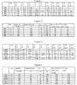
- Figure 3 is a table giving the values of radii and index differences for some examples of profiles of H0M type chromatic dispersion-compensating optical fibres according to the invention for use in compensating an NZ-DSF optical fibre.
- Figure 3 is similar to Figure 1, but the left-hand column gives the denomination of the profiles from H0M7 to H0M12.
- Figure 4 is a table giving other properties of the profiles of H0M type chromatic dispersion-compensating optical fibres according to the invention shown in Figure 3 for the mode LP 02 .
- Optical fibres having four slices and preferably five slices make it possible to achieve better compromises between the most negative chromatic dispersion possible, the greatest effective area possible and the most linear chromatic dispersion slope possible over the operational spectral range under consideration.
- a minimum dispersion wavelength within the preferred narrow range of from 1540 nm to 1560 nm also makes it possible to improve the compromise.
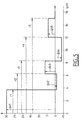
- Figure 5 shows diagrammatically a five-slice profile type of an H0M type chromatic dispersion-compensating optical fibre according to the invention.
- Plotted along the abscissa are the radii in ⁇ m.
- Plotted along the ordinate are the index differences multiplied by a thousand without units.
- the first slice called the central slice, has a maximum index difference ⁇ n 1 with the constant index of the cladding and an outer radius r 1 .
- the maximum index difference ⁇ n 1 is positive.
- the index is preferably constant.
- the second slice called the first peripheral slice, has an index difference ⁇ n 2 with the constant index of the cladding and an outer radius r 2 .
- the index difference ⁇ n 2 can be positive or negative.
- a negative index difference corresponds to a buried slice.
- the index is preferably constant between radius r 1 and radius r 2 .
- the third slice called the second peripheral slice, has an index difference ⁇ n 3 with the constant index of the cladding and an outer radius r 3 .
- the index difference ⁇ n 3 can be positive or negative.
- the index is preferably constant between radius r 2 and radius r 3 .
- the fourth slice called the third peripheral slice, has an index difference ⁇ n 4 with the constant index of the cladding and an outer radius r 4 .
- the index difference ⁇ n 4 can be positive or negative.
- the index is preferably constant between radius r 3 and radius r 4 .
- the fifth slice has an index difference ⁇ n 5 with the constant index of the cladding and an outer radius r 5 .
- the index difference ⁇ n 5 can be positive or negative.
- the index is preferably constant between radius r 4 and radius r 5 .
- Beyond the radius r 5 is the cladding of constant index.
- the cladding of constant index starts from the radius r 4 .
- the cladding of constant index starts from the radius r 3 .
- Figure 6 shows diagrammatically an optical fibre wavelength multiplexing transmission system according to the invention.
- the transmission system comprises successively in series the following elements, viewed from upstream to downstream from the point of view of the propagation of the light signal: a line optical fibre 1 followed by a compensation module 3 which comprises first of all a mode converter 2 that converts most of the light energy being propagated according to the fundamental mode LP 01 to a higher order mode, for example LP 02 , and then an H0M type chromatic dispersion-compensating optical fibre 4 according to the invention, compensating for the chromatic dispersion of the line optical fibre 1 but in the higher order mode LP 02 , and then a mode converter 5 that converts most of the light energy being propagated according to the higher order mode LP 02 back to the fundamental mode LP 01 .
- the transmission system according to the invention may also comprise other elements not shown in Figure 6 for reasons of clarity, such as transmitters, receivers, amplifiers, and/or may contain the sequence of elements shown in Figure 6 several times.
- the losses caused by bending for a radius of 10 mm, at a wavelength of 1495 nm are less than 100 dB/m, advantageously less than 50 dB/m.
- the attenuation, at a wavelength of 1495 nm is less than 1.5 dB/km, advantageously less than 1 dB/km.
- the polarisation mode dispersion, at a wavelength of 1495 nm, is less than 0.5 ps/km 1/2 , advantageously less than 0.2 ps/km 1/2 .
Abstract
Description
- The invention relates to the field of chromatic dispersion-compensating optical fibres for a wavelength multiplexing transmission system. The function of the dispersion-compensating optical fibre is to compensate for the chromatic dispersion of a so-called line fibre. The invention relates more precisely to an chromatic dispersion-compensating optical fibre in the S-band for use in compensating for the chromatic dispersion of either a standard SMF optical fibre or of an NZ-DSF optical fibre, where the line optical fibre carries an optical signal in the spectral band in use, which is the S-band extending from 1460 nm to 1530 nm.
- According to a first item of prior art, described in Patent Application FR 0204271, which is hereby incorporated by reference, there is known an example of an H0M chromatic dispersion-compensating optical fibre (or higher order mode optical fibre) in the C-band and/or L-band, which exhibits slight variations in the chromatic dispersion slope in the C- and/or L-band, thus enabling good compensation for chromatic dispersion and for the chromatic dispersion slope of the line optical fibre. That compensating optical fibre is not, however, suitable for use in the S-band. Its minimum chromatic dispersion wavelength is too high and too far removed from the S-band. The minimum chromatic dispersion wavelength is the wavelength corresponding to a global chromatic dispersion minimum.
- According to a second item of prior art, described in
European Patent EP 1 351 417 of the present Applicant, there is known a dispersion-compensating optical fibre for a wavelength multiplexing transmission system, comprising, from the centre towards the periphery, a core having a variable index profile then a cladding of constant index, wherein, the chromatic dispersion is less than - 150 ps/nm.km, the chromatic dispersion slope is strictly negative, and the effective area is greater than 40 µm2. Furthermore, the difference between the wavelength corresponding to the overall minimum chromatic dispersion and the wavelength corresponding to an upper limit of an operating spectral range greater than 30 nm is greater than 35 nm, and the relative variation of the dispersion slope over said operating spectral range has an absolute value less than 30 %. - According to a third item of prior art, described in US Patent Application US2003/0185531, there is known a limited mode dispersion compensating optical fiber supporting at least one high order spatial mode comprising: a plurality of core areas, the refractive index profile of which are selected to result in an optical waveguide providing in the LP02 mode: dispersion more negative than -300 ps/nm/km at a representative wavelength, designated λ0, within an operative waveband; projected zero dispersion less than (λ0-75 nm), where projected zero dispersion is defined as λ0-Dispersion (λ0)/Slope (λ0); and third order dispersion less than 2 % over the operative waveband, where third order dispersion is defined as the maximum deviation from a best line fit for dispersion divided the best fit dispersion at λ0, said best fit line chosen to minimize said maximum deviation.
- The solution proposed by the invention accordingly relates to an H0M dispersion-compensating optical fibre in the S-band exhibiting as small variations as possible in the chromatic dispersion slope in order to enable effective compensation for chromatic dispersion and for the chromatic dispersion slope across the entire S-band. In order to do so, the minimum chromatic dispersion wavelength is selected from a narrow and optimum spectral range in order to ensure a good compromise between the low level of variation in the chromatic dispersion slope in the S-band, the high value for effective area, the very negative chromatic dispersion value, and a chromatic dispersion to chromatic dispersion slope ratio that is as close as possible to that of the line optical fibre to be compensated. Depending on whether the compensation is for a standard SMF (single mode fibre) optical fibre or for an NZ-DSF (non-zero dispersion shifted fibre) optical fibre, the optimum range for the minimum chromatic dispersion wavelength and the compromise between the parameters and optical properties being sought are slightly different.
- In order to compensate a standard SMF optical fibre carrying an optical signal in the S-band, according to the invention there is provided an chromatic dispersion-compensating optical fibre in the spectral band S extending from 1460 nm to 1530 nm for a wavelength multiplexing transmission system, comprising successively, from the centre to the periphery, a core having a variable index profile and then a cladding of constant index, enabling the propagation, at a wavelength of 1495 nm, in addition to the fundamental mode LP01, of at least one higher order mode, the index profile of the core being determined in such a manner that, for said higher mode, on the one hand at a wavelength of 1495 nm, firstly the chromatic dispersion is less than -150 ps/nm-km, secondly the chromatic dispersion to chromatic dispersion slope ratio is between 200 nm and 300 nm, and thirdly the effective area is greater than 60 µm2 and, on the other hand, the wavelength corresponding to the global chromatic dispersion minimum is between 1550 nm and 1600 nm.
- In order to enable more precise compensation for the chromatic dispersion of a standard SMF optical fibre across the entire S-band, preferably the index profile of the core is determined in such a manner that, for said higher mode, at a wavelength of 1495 nm, the chromatic dispersion to chromatic dispersion slope ratio is between 200 nm and 250 nm.
- In order to improve the compromise achieved between the optical properties of the dispersion-compensating optical fibre according to the invention whilst preserving a low variation in the chromatic dispersion slope across the entire S-band, preferably the index profile of the core is determined in such a manner that, for said higher mode, at a wavelength of 1495 nm, the wavelength corresponding to the global chromatic dispersion minimum is between 1570 nm and 1590 nm.
- In order to improve the quality of the compensation of the H0M type chromatic dispersion-compensating optical fibre according to the invention and its other properties, a number of preferred ranges for the indices and the radii of the index profile of the core will now be given. The expression "remains less than" means "is less than" if the parameter is constant and means "remains less than" over the slice under consideration if the parameter is variable over the slice under consideration.
- Preferably the index profile of the core is determined in such a manner that, for said higher mode, at a wavelength of 1495 nm, the effective area is greater than 70 µm2, and preferably greater than 80 µm2.
- Preferably the maximum index difference Δn1 between the index of the central slice and the index of the cladding is between 20.10-3 and 32.10-3 and the outer radius r1 of the central slice is between 3 µm and 4.5 µm.
- Preferably the value of the integralof the index difference relative to the cladding, between a zero radius and the radius r1 of the portion of the central slice having an index higher than the index of the cladding, is between 100.10-3 and 115.10-3 µm.

- Preferably the value of twice the integralof the product of the index difference relative to the cladding times the radius, between a zero radius and the radius r1 of the portion of the central slice having an index higher than the index of the cladding, is between 325.10-3 µm2 and 475.10-3 µm2.

- Preferably the value of twice the integralof the product of the index difference relative to the cladding times the radius, between a zero radius and the radius r3 of the second peripheral slice, is between 400.10-3 µm2 and 800.10-3 µm2.

- Preferably the index difference Δn2 between the index of the first peripheral slice and the index of the cladding is between -4.10-3 and 5.10-3 and the outer radius r2 of the first peripheral slice is between 5 µm and 11 µm.
- Preferably the index difference Δn3 between the index of the second peripheral slice and the index of the cladding is between -5.10-3 and 5.10-3 and the outer radius r3 of the second peripheral slice is between 8 µm and 15 µm.
- Preferably the index difference Δn4 between the index of the third peripheral slice and the index of the cladding is between -5.10-3 and 5.10-3 and the outer radius r4 of the third peripheral slice is between 11 µm and 17 µm.
- Preferably the index difference Δn5 between the index of the fourth peripheral slice and the index of the cladding is between 0 and 10.10-3 and the outer radius r5 of the fourth peripheral slice is between 14 µm and 17 µm.
- To compensate an NZ-DSF optical fibre carrying an optical signal in the S-band, according to the invention there is provided an chromatic dispersion-compensating optical fibre in the spectral band S extending from 1460 nm to 1530 nm, for a wavelength multiplexing transmission system, comprising successively, from the centre to the periphery, a core having a variable index profile and then a cladding of constant index, enabling the propagation, at a wavelength of 1495 nm, in addition to the fundamental mode LP01, of at least one higher order mode, the index profile of the core being determined in such a manner that, for said higher mode, on the one hand at a wavelength of 1495 nm, firstly the chromatic dispersion is lower than -150 ps/nm-km, secondly the chromatic dispersion to chromatic dispersion slope ratio is less than 130 nm and thirdly the effective area is greater than 50 µm2 and, on the other hand, the wavelength corresponding to the global chromatic dispersion minimum is between 1530 nm and 1580 nm.
- In order to enable more precise compensation for the chromatic dispersion of a standard SMF optical fibre across the entire S-band, preferably the index profile of the core is determined in such a manner that, for said higher mode, at a wavelength of 1495 nm, the chromatic dispersion to chromatic dispersion slope ratio is between 90 nm and 110 nm.
- In order to improve the compromise achieved between the optical properties of the dispersion-compensating optical fibre according to the invention whilst preserving a low variation in the chromatic dispersion slope across the entire S-band, preferably the index profile of the core is determined in such a manner that, for said higher mode, at a wavelength of 1495 nm, the wavelength corresponding to the global chromatic dispersion minimum is between 1540 nm and 1560 nm.
- In order to improve the quality of the compensation of the H0M type chromatic dispersion-compensating optical fibre according to the invention and its other properties, a number of preferred ranges for the indices and radii of the index profile of the core will be given. The expression "remains less than" means "is less than" if the parameter is constant and means "remains less than" over the slice under consideration if the parameter is variable over the slice under consideration.
- Preferably the index profile of the core is determined in such a manner that, for said higher mode, at a wavelength of 1495 nm, the effective area is greater than 65 µm2, preferably greater than 80 µm2.
- Preferably the maximum index difference Δn1 between the index of the central slice and the index of the cladding is between 15.10-3 and 30.10-3 and the outer radius r1 of the central slice is between 3.5 µm and 5 µm.
- Preferably the value of twice the integralof the product of the index difference relative to the cladding times the radius, between a zero radius and the radius r1 of the portion of the central slice having an index higher than the index of the cladding, is between 375.10-3 µm2 and 525.10-3 µm2.

- Preferably the value of twice the integralof the product of the index difference relative to the cladding times the radius, between a zero radius and the radius r3 of the second peripheral slice, is between 400.10-3 µm2 and 700.10-3 µm2.

- Preferably the index difference Δn2 between the index of the first peripheral slice and the index of the cladding is between -7.10-3 and 5.10-3 and the outer radius r2 of the first peripheral slice is between 5 µm and 10 µm.
- Preferably the index difference Δn3 between the index of the second peripheral slice and the index of the cladding is between -5.10-3 and 5.10-3 and the outer radius r3 of the second peripheral slice is between 7 µm and 15 µm.
- Preferably the index difference Δn4 between the index of the third peripheral slice and the index of the cladding is between -5.10-3 and 5.10-3 and the outer radius r4 of the third peripheral slice is between 10 µm and 16 µm.
- Preferably the index difference Δn5 between the index of the fourth peripheral slice and the index of the cladding is between 0 and 10.10-3 and the outer radius r5 of the fourth peripheral slice is between 14 µm and 17 µm.
- Whether the compensation is for a standard SMF optical fibre or an NZ-DSF optical fibre, the optical fibre preferably has the following advantageous characteristics.
- Preferably the higher order mode is the mode LP02, for which mode chromatic dispersion-compensating optical fibres exhibiting very negative chromatic dispersions can readily be obtained, and which mode is not very sensitive to defects in the circular geometry of the fibre, which defects are responsible for the polarisation problems. Other higher order modes are, however, possible, such as for example the mode LP11 or the mode LP03.
- Preferably the index profile of the core is determined in such a manner that, for said higher mode, at a wavelength of 1495 nm, the chromatic dispersion is less than -200 ps/nm-km, preferably less than -250 ps/nm-km, advantageously less than -300 ps/nm-km, which makes it possible, for a given line optical fibre, to reduce the length of the compensation optical fibre to be used.
- The operational spectral band used is the S-band from 1460 nm to 1530 nm. An optical fibre wavelength multiplexing transmission system, described in greater detail hereinafter, integrating an H0M type dispersion-compensating optical fibre according to the invention will preferably have an absolute value for cumulative chromatic dispersion for each wavelength between 1460 nm and 1530 nm of less than 30 ps/nm on average over 100 km of transmission.
- Preferably the index profile of the core comprises at least four slices. The index profile of the core advantageously comprises at least five slices. The more negative the chromatic dispersion, the higher the number of slices in the index profile of the core required to obtain good linearity of the curve for the chromatic dispersion as a function of the wavelength for the H0M type dispersion-compensating optical fibre according to the invention. That high number of slices makes it possible to obtain an H0M type chromatic dispersion-compensating optical fibre that, whilst enabling very good compensation for chromatic dispersion, does not have too serious an effect on the other properties of said H0M type chromatic dispersion-compensating optical fibre. Five slices constitutes a good compromise between the properties of the H0M type dispersion-compensating optical fibre and the complexity of its manufacture, for compensation in the spectral band S. The shape of the slices is, for example, rectangular, but it may also be triangular, trapezoidal or alpha-shaped.
- In a first preferred embodiment of the invention, the H0M type chromatic dispersion-compensating optical fibre according to the invention comprises a variable index profile of a core having four slices. The variable index profile of the core thus comprises successively, from the centre to the periphery, a central slice having a maximum index higher than the index of the cladding, a first peripheral slice having a maximum index less than the maximum index of the central slice, a second peripheral slice having a maximum index less than the maximum index of the central slice, and a third peripheral slice having a maximum index less than the maximum index of the central slice.
- In a second preferred embodiment of the invention, the H0M type optical fibre providing dispersion compensation according to the invention comprises a variable index profile of a core having five slices. The variable index profile of the core accordingly comprises successively, from the centre to the periphery, a central slice having a maximum index higher than the index of the cladding, a first peripheral slice having a maximum index less than the maximum index of the central slice, a second peripheral slice having a maximum index less than the maximum index of the central slice, a third peripheral slice having a maximum index less than the maximum index of the central slice, and a fourth peripheral slice having a maximum index less than the maximum index of the central slice.
- The invention relates also to a chromatic dispersion compensation module integrating an H0M type chromatic dispersion-compensating optical fibre according to the invention. Preferably that module comprises successively in series a first mode converter capable of converting the fundamental mode to the higher order mode, an dispersion-compensating optical fibre according to the invention and a second mode converter capable of converting the higher order mode back to the fundamental mode. That module may be integrated in an optical fibre wavelength multiplexing transmission system, which system accordingly comprises successively in series a line optical fibre and a compensation module according to the invention. In that optical fibre wavelength multiplexing transmission system according to the invention, the ratio between the length of the line optical fibre and the length of the dispersion compensation optical fibre is preferably more or less the inverse of the absolute value of the ratio between the chromatic dispersion of the line optical fibre at a wavelength of 1495 nm and the chromatic dispersion of the chromatic dispersion compensation optical fibre at a wavelength of 1495 nm, in order to enable optimised compensation.
- The invention will be better understood and other particularities and advantages will become apparent from the description given hereinbelow and the attached drawings, given by way of example, wherein:
- Figure 1 is a table giving the values of radii and index differences for some examples of profiles of H0M type chromatic dispersion-compensating optical fibres according to the invention for use in compensating a standard SMF optical fibre;
- Figure 2 is a table giving other properties of the profiles of H0M type chromatic dispersion-compensating optical fibres according to the invention shown in Figure 1 for the mode LP02;
- Figure 3 is a table giving the values of radii and index differences for some examples of profiles of H0M type chromatic dispersion-compensating optical fibres according to the invention for use in compensating an NZ-DSF optical fibre;
- Figure 4 is a table giving other properties of the profiles of H0M type chromatic dispersion-compensating optical fibres according to the invention shown in Figure 1 for the mode LP02;
- Figure 5 shows diagrammatically a type of index profile comprising five slices of an H0M type chromatic dispersion-compensating optical fibre according to the invention; and
- Figure 6 shows diagrammatically an optical fibre wavelength multiplexing transmission system according to the invention.
- Figure 1 is a table giving the values of radii and index differences for some examples of profiles of H0M type dispersion-compensating optical fibres according to the invention for use in compensating a standard SMF optical fibre. The left-hand column shows the denomination of the profiles from H0M1 to H0M5. The second column indicates the number of slices that the core index profile of the example under consideration comprises. The next five columns give radii of the core variable index profile in µm. The last five columns give the index differences relative to the cladding of constant index multiplied by a thousand (no units). Not all the boxes in the Table have been completed, since the profiles do not all have the same number of slices.
- Figure 2 is a table giving other properties of the profiles of H0M type chromatic dispersion-compensating optical fibres according to the invention shown in Figure 1 for the mode LP02. The left-hand column gives the denomination of the profiles already explained above. The next column indicates the number of slices that each profile under consideration comprises. For each profile under consideration, the other columns give properties of the slice of optical fibre corresponding to the profile under consideration. The next column gives the chromatic dispersion in ps/nm-km at a wavelength of 1495 nm. The next column gives the chromatic dispersion to chromatic dispersion slope ratio in nm at a wavelength of 1495 nm. The next column gives the effective area Aeff in µm2 at a wavelength of 1495 nm. The next column gives the minimum chromatic dispersion wavelength λmin in nm. The last two columns give the maximum relative variations in chromatic dispersion slope as a %, respectively, for operational spectral ranges from 1475 nm to 1515 nm and from 1465 nm to 1525 nm. The relative variation in the dispersion slope over an operational spectral range corresponds to the quotient between, on the one hand, the difference between the maximum chromatic dispersion slope over said operational spectral range and the minimum chromatic dispersion slope over said operational spectral range and, on the other hand, the mean chromatic dispersion slope for said operational spectral range. Optical fibres having four slices and preferably five slices make it possible to achieve better compromises between the most negative chromatic dispersion possible, the greatest effective area possible and the most linear chromatic dispersion slope possible over the operational spectral range under consideration. A minimum dispersion wavelength in the preferred narrow range of from 1570 nm to 1590 nm also makes it possible to improve the compromise.
- Figure 3 is a table giving the values of radii and index differences for some examples of profiles of H0M type chromatic dispersion-compensating optical fibres according to the invention for use in compensating an NZ-DSF optical fibre. Figure 3 is similar to Figure 1, but the left-hand column gives the denomination of the profiles from H0M7 to H0M12.
- Figure 4 is a table giving other properties of the profiles of H0M type chromatic dispersion-compensating optical fibres according to the invention shown in Figure 3 for the mode LP02. Optical fibres having four slices and preferably five slices make it possible to achieve better compromises between the most negative chromatic dispersion possible, the greatest effective area possible and the most linear chromatic dispersion slope possible over the operational spectral range under consideration. A minimum dispersion wavelength within the preferred narrow range of from 1540 nm to 1560 nm also makes it possible to improve the compromise. The linearity of the chromatic dispersion slope of Examples H0M7, H0M10 and H0M12, the minimum dispersion wavelengths of which are outside said minimum chromatic dispersion wavelength range is appreciably worse than that of the other Examples, their effective areas also being smaller. The attempt to find a low chromatic dispersion to chromatic dispersion slope ratio-seems to have a deleterious effect on the compromise obtained, as shown by the poor linearity of the chromatic dispersion slope of Example H0M12. The most interesting Examples correspond to a threshold of 30% for the column on the far right of the table. That threshold of 30% also applies for chromatic dispersion-compensating optical fibres for use in compensating a standard SMF line optical fibre.
- Figure 5 shows diagrammatically a five-slice profile type of an H0M type chromatic dispersion-compensating optical fibre according to the invention. Plotted along the abscissa are the radii in µm. Plotted along the ordinate are the index differences multiplied by a thousand without units. The first slice, called the central slice, has a maximum index difference Δn1 with the constant index of the cladding and an outer radius r1. The maximum index difference Δn1 is positive. Between a zero radius and the radius r1, the index is preferably constant. The second slice, called the first peripheral slice, has an index difference Δn2 with the constant index of the cladding and an outer radius r2. The index difference Δn2 can be positive or negative. A negative index difference corresponds to a buried slice. The index is preferably constant between radius r1 and radius r2. The third slice, called the second peripheral slice, has an index difference Δn3 with the constant index of the cladding and an outer radius r3. The index difference Δn3 can be positive or negative. The index is preferably constant between radius r2 and radius r3. The fourth slice, called the third peripheral slice, has an index difference Δn4 with the constant index of the cladding and an outer radius r4. The index difference Δn4 can be positive or negative. The index is preferably constant between radius r3 and radius r4. The fifth slice, called the fourth peripheral slice, has an index difference Δn5 with the constant index of the cladding and an outer radius r5. The index difference Δn5 can be positive or negative. The index is preferably constant between radius r4 and radius r5. Beyond the radius r5 is the cladding of constant index. For optical fibres having only four slices, the cladding of constant index starts from the radius r4. For optical fibres having only three slices, the cladding of constant index starts from the radius r3.
- Figure 6 shows diagrammatically an optical fibre wavelength multiplexing transmission system according to the invention. The transmission system comprises successively in series the following elements, viewed from upstream to downstream from the point of view of the propagation of the light signal: a line
optical fibre 1 followed by acompensation module 3 which comprises first of all amode converter 2 that converts most of the light energy being propagated according to the fundamental mode LP01 to a higher order mode, for example LP02, and then an H0M type chromatic dispersion-compensatingoptical fibre 4 according to the invention, compensating for the chromatic dispersion of the lineoptical fibre 1 but in the higher order mode LP02, and then amode converter 5 that converts most of the light energy being propagated according to the higher order mode LP02 back to the fundamental mode LP01. The transmission system according to the invention may also comprise other elements not shown in Figure 6 for reasons of clarity, such as transmitters, receivers, amplifiers, and/or may contain the sequence of elements shown in Figure 6 several times. - Preferably the losses caused by bending for a radius of 10 mm, at a wavelength of 1495 nm, are less than 100 dB/m, advantageously less than 50 dB/m.
- Preferably the attenuation, at a wavelength of 1495 nm, is less than 1.5 dB/km, advantageously less than 1 dB/km.
- Preferably the polarisation mode dispersion, at a wavelength of 1495 nm, is less than 0.5 ps/km1/2, advantageously less than 0.2 ps/km1/2.
Claims (48)
- Chromatic dispersion-compensating optical fibre in the S-band extending from 1460 nm to 1530 nm, for a wavelength multiplexing transmission system, comprising successively, from the centre to the periphery, a core having a variable index profile and then a cladding of constant index, enabling the propagation, at a wavelength of 1495 nm, in addition to the fundamental mode LP01, of at least one higher order mode, the index profile of the core being determined in such a manner that, for said higher mode, on the one hand at a wavelength of 1495 nm, firstly the chromatic dispersion is less than -150 ps/nm-km, secondly the chromatic dispersion to chromatic dispersion slope ratio is between 200 nm and 300 nm, and thirdly the effective area is greater than 60 µm2, and, on the other hand, the wavelength corresponding to the global chromatic dispersion minimum is between 1550 nm and 1600 nm.
- Dispersion-compensating optical fibre according to claim 1, characterised in that the index profile of the core is determined in such a manner that, for said higher mode, at a wavelength of 1495 nm, the chromatic dispersion is less than -200 ps/nm-km.
- Dispersion-compensating optical fibre according to claim 2, characterised in that the index profile of the core is determined in such a manner that, for said higher mode, at a wavelength of 1495 nm, the chromatic dispersion is less than -250 ps/nm-km.
- Dispersion-compensating optical fibre according to claim 3, characterised in that the index profile of the core is determined in such a manner that, for said higher mode, at a wavelength of 1495 nm, the chromatic dispersion is less than -300 ps/nm-km.
- Dispersion-compensating optical fibre according to any one of the preceding claims, characterised in that the higher order mode is the mode LP02.
- Dispersion-compensating optical fibre according to any one of the preceding claims, characterised in that the index profile of the core is determined in such a manner that, for said higher mode, at a wavelength of 1495 nm, the chromatic dispersion to chromatic dispersion slope ratio is between 200 nm and 250 nm.
- Dispersion-compensating optical fibre according to any one of the preceding claims, characterised in that the index profile of the core is determined in such a manner that, for said higher mode, at a wavelength of 1495 nm, the effective area is greater than 70 µm2.
- Dispersion-compensating optical fibre according to claim 7, characterised in that the index profile of the core is determined in such a manner that, for said higher mode, at a wavelength of 1495 nm, the effective area is greater than 80 µm2.
- Dispersion-compensating optical fibre according to any one of the preceding claims, characterised in that the index profile of the core is determined in such a manner that, for said higher mode, at a wavelength of 1495 nm, the wavelength corresponding to the global chromatic dispersion minimum is between 1570 nm and 1590 nm.
- Dispersion-compensating optical fibre according to any one of the preceding claims, characterised in that the variable index profile of the core comprises successively, from the centre to the periphery,
a central slice having a maximum index higher than the index of the cladding,
a first peripheral slice having a maximum index less than the maximum index of the central slice,
a second peripheral slice having a maximum index less than the maximum index of the central slice, and
a third peripheral slice having a maximum index less than the maximum index of the central slice. - Dispersion-compensating optical fibre according to claim 10, characterised in that the maximum index difference (Δn1) between the index of the central slice and the index of the cladding is between 20.10-3 and 32.10-3 and in that the outer radius (r1) of the central slice is between 3 µm and 4.5 µm.
- Dispersion-compensating optical fibre according to either claim 10 or claim 11, characterised in that the value of the integralof the index difference relative to the cladding, between a zero radius and the radius (r1) of the portion of the central slice having an index higher than the index of the cladding, is between 100.10-3 and 115.10-3 µm.

- Dispersion-compensating optical fibre according to any one of claims 10 to 12, characterised in that the value of twice the integralof the product of the index difference relative to the cladding times the radius, between a zero radius and the radius (r1) of the portion of the central slice having an index higher than the index of the cladding, is between 325.10-3 µm2 and 475.10-3 µm2.

- Dispersion-compensating optical fibre according to any one of claims 10 to 13, characterised in that the value of twice the integralof the product of the index difference relative to the cladding times the radius, between a zero radius and the radius (r3) of the second peripheral slice, is between 400.10-3 µm2 and 800.10-3 µm2.

- Dispersion-compensating optical fibre according to any one of claims 10 to 14, characterised in that the index difference (Δn2) between the index of the first peripheral slice and the index of the cladding is between -4.10-3 and 5.10-3 and in that the outer radius (r2) of the first peripheral slice is between 5 µm and 11 µm.
- Dispersion-compensating optical fibre according to any one of claims 10 to 15, characterised in that the index difference (Δn3) between the index of the second peripheral slice and the index of the cladding is between -5.10-3 and 5.10-3 and in that the outer radius (r3) of the second peripheral slice is between 8 µm and 15 µm.
- Dispersion-compensating optical fibre according to any one of claims 10 to 16, characterised in that the index difference (Δn4) between the index of the third peripheral slice and the index of the cladding is between -5.10-3 and 5.10-3 and in that the outer radius (r4) of the third peripheral slice is between 11 µm and 17 µm.
- Dispersion-compensating optical fibre according to any one of claims 10 to 17, characterised in that the variable index profile of the core comprises a fourth peripheral slice having a maximum index less than the maximum index of the central slice, said fourth peripheral slice being situated at the periphery of the third peripheral slice.
- Dispersion-compensating optical fibre according to claim 18, characterised in that the index difference (Δn5) between the index of the fourth peripheral slice and the index of the cladding is between 0 and 10.10-3 and in that the outer radius (r5) of the fourth peripheral slice is between 14 µm and 17 µm.
- Chromatic dispersion-compensating optical fibre in the S-band extending from 1460 nm to 1530 nm, for a wavelength multiplexing transmission system, comprising successively, from the centre to the periphery, a core having a variable index profile and then a cladding of constant index, enabling the propagation, at a wavelength of 1495 nm, in addition to the fundamental mode LP01, of at least one higher order mode, the index profile of the core being determined in such a manner that, for said higher mode, on the one hand at a wavelength of 1495 nm, firstly the chromatic dispersion is less than -150 ps/nm-km, secondly the chromatic dispersion to chromatic dispersion slope ratio is less than 130 nm, and thirdly the effective area is greater than 50 µm2, and, on the other hand, the wavelength corresponding to the global chromatic dispersion minimum is between 1530 nm and 1580 nm.
- Dispersion-compensating optical fibre according to claim 20, characterised in that the index profile of the core is determined in such a manner that, for said higher mode, at a wavelength of 1495 nm, the chromatic dispersion is less than -200 ps/nm-km.
- Dispersion-compensating optical fibre according to claim 21, characterised in that the index profile of the core is determined in such a manner that, for said higher mode, at a wavelength of 1495 nm, the chromatic dispersion is less than -250 ps/nm-km.
- Dispersion-compensating optical fibre according to claim 22, characterised in that the index profile of the core is determined in such a manner that, for said higher mode, at a wavelength of 1495 nm, the chromatic dispersion is less than -300 ps/nm-km.
- Dispersion-compensating optical fibre according to any one of the preceding claims, characterised in that the higher order mode is the mode LP02.
- Dispersion-compensating optical fibre according to any one of the preceding claims, characterised in that the index profile of the core is determined in such a manner that, for said higher mode, at a wavelength of 1495 nm, the chromatic dispersion to chromatic dispersion slope ratio is between 90 nm and 110 nm.
- Dispersion-compensating optical fibre according to any one of the preceding claims, characterised in that the index profile of the core is determined in such a manner that, for said higher mode, at a wavelength of 1495 nm, the effective area is greater than 65 µm2.
- Dispersion-compensating optical fibre according to claim 26, characterised in that the index profile of the core is determined in such a manner that, for said higher mode, at a wavelength of 1495 nm, the effective area is greater than 80 µm2.
- Dispersion-compensating optical fibre according to any one of the preceding claims, characterised in that the index profile of the core is determined in such a manner that, for said higher mode, at a wavelength of 1495 nm, the wavelength corresponding to the global chromatic dispersion minimum is between 1540 nm and 1560 nm.
- Dispersion-compensating optical fibre according to any one of the preceding claims, characterised in that the variable index profile of the core comprises successively, from the centre to the periphery,
a central slice having a maximum index higher than the index of the cladding,
a first peripheral slice having a maximum index less than the maximum index of the central slice,
a second peripheral slice having a maximum index less than the maximum index of the central slice, and
a third peripheral slice having a maximum index less than the maximum index of the central slice. - Dispersion-compensating optical fibre according to claim 29, characterised in that the maximum index difference (Δn1) between the index of the central slice and the index of the cladding is between 15.10-3 and 30.10-3 and in that the outer radius (r1) of the central slice is between 3.5 µm and 5 µm.
- Dispersion-compensating optical fibre according to either claim 29 or claim 30, characterised in that the value of twice the integralof the product of the index difference relative to the cladding times the radius, between a zero radius and the radius (r1) of the portion of the central slice having an index higher than the index of the cladding, is between 375.10-3 and 525.10-3 µm2.

- Dispersion-compensating optical fibre according to any one of claims 29 to 31, characterised in that the value of twice the integralof the product of the index difference relative to the cladding times the radius, between a zero radius and the radius (r3) of the second peripheral slice, is between 400.10-3 µm2 and 700.10-3 µm2.

- Dispersion-compensating optical fibre according to any one of claims 29 to 32, characterised in that the index difference (Δn2) between the index of the first peripheral slice and the index of the cladding is between -7.10-3 and 5.10-3 and in that the outer radius (r2) of the first peripheral slice is between 5 µm and 10 µm.
- Dispersion-compensating optical fibre according to any one of claims 29 to 33, characterised in that the index difference (Δn3) between the index of the second peripheral slice and the index of the cladding is between -5.10-3 and 5.10-3 and in that the outer radius (r3) of the second peripheral slice is between 7 µm and 15 µm.
- Dispersion-compensating optical fibre according to any one of claims 29 to 34, characterised in that the index difference (Δn4) between the index of the third peripheral slice and the index of the cladding is between -5.10-3 and 5.10-3 and in that the outer radi us (r4) of the third peripheral slice is between 10 µm and 16 µm.
- Dispersion-compensating optical fibre according to any one of claims 29 to 35, characterised in that the variable index profile of the core comprises a fourth peripheral slice having a maximum index less than the maximum index of the central slice, said fourth peripheral slice being situated at the periphery of the third peripheral slice.
- Dispersion-compensating optical fibre according to claim 18, characterised in that the index difference (Δn5) between the index of the fourth peripheral slice and the index of the cladding is between 0 and 10.10-3 and in that the outer radius (r5) of the fourth peripheral slice is between 14 µm and 17 µm.
- Dispersion-compensating optical fibre according to any one of the preceding claims, characterised in that the losses caused by bending for a radius of 10 mm, at a wavelength of 1495 nm, are less than 100 dB/m.
- Dispersion-compensating optical fibre according to claim 38, characterised in that the losses caused by bending for a radius of 10 mm, at a wavelength of 1495 nm, are less than 50 dB/m.
- Dispersion-compensating optical fibre according to any one of the preceding claims, characterised in that the attenuation, at a wavelength of 1495 nm, is less than 1.5 dB/km.
- Dispersion-compensating optical fibre according to claim 40, characterised in that the attenuation, at a wavelength of 1495 nm, is less than 1 dB/km.
- Dispersion-compensating optical fibre according to any one of the preceding claims, characterised in that the polarisation mode dispersion, at a wavelength of 1495 nm, is less than 0.5 ps/km1/2.
- Dispersion-compensating optical fibre according to claim 42, characterised in that the polarisation mode dispersion, at a wavelength of 1495 nm, is less than 0.2 ps/km1/2.
- Chromatic dispersion compensation module, characterised in that said module (3) comprises a dispersion-compensating optical fibre (4) according to any one of the preceding claims.
- Chromatic dispersion compensation module according to claim 44, characterised in that said module (3) comprises successively in series a first mode converter (2) capable of converting the fundamental mode to the higher order mode, said dispersion-compensating optical fibre (4) and a second mode converter (5) capable of converting the higher order mode back to the fundamental mode.
- Optical fibre wavelength multiplexing transmission system, characterised in that said system comprises successively in series a line optical fibre (1) and a compensation module (3) according to either claim 44 or claim 45.
- Optical fibre wavelength multiplexing transmission system according to claim 46, characterised in that the ratio between the length of the line optical fibre (1) and the length of the dispersion-compensating optical fibre (4) is more or less the inverse of the absolute value of the ratio between the chromatic dispersion of the line optical fibre (1) at a wavelength of 1495 nm and the chromatic dispersion of the dispersion-compensating optical fibre (4) at a wavelength of 1495 nm.
- Optical fibre wavelength multiplexing transmission system according to either claim 46 or claim 47, characterised in that the absolute value for the cumulative chromatic dispersion for each wavelength between 1460 nm and 1530 nm is less than 30 ps/nm on average over 100 km of transmission.
Applications Claiming Priority (2)
| Application Number | Priority Date | Filing Date | Title |
|---|---|---|---|
| FR0450525A FR2867865B1 (en) | 2004-03-16 | 2004-03-16 | CHROMATIC BAND DISPERSION COMPENSATION OPTICAL FIBER USING HIGHER ORDER MODE |
| FR0450525 | 2004-03-16 |
Publications (1)
| Publication Number | Publication Date |
|---|---|
| EP1577688A1 true EP1577688A1 (en) | 2005-09-21 |
Family
ID=34834278
Family Applications (1)
| Application Number | Title | Priority Date | Filing Date |
|---|---|---|---|
| EP05075590A Ceased EP1577688A1 (en) | 2004-03-16 | 2005-03-10 | Chromatic dispersion-compensating optical fibre in the S-band using a higher order mode |
Country Status (5)
| Country | Link |
|---|---|
| US (2) | US7369732B2 (en) |
| EP (1) | EP1577688A1 (en) |
| JP (1) | JP2005266808A (en) |
| CN (1) | CN100397118C (en) |
| FR (1) | FR2867865B1 (en) |
Families Citing this family (3)
| Publication number | Priority date | Publication date | Assignee | Title |
|---|---|---|---|---|
| FR2867865B1 (en) * | 2004-03-16 | 2008-05-30 | Cit Alcatel | CHROMATIC BAND DISPERSION COMPENSATION OPTICAL FIBER USING HIGHER ORDER MODE |
| AU2008213822B2 (en) * | 2007-02-05 | 2013-08-29 | Ofs Fitel, Llc. | Segmented gain-doping of an optical fiber |
| JP7095473B2 (en) * | 2018-08-07 | 2022-07-05 | 日本電信電話株式会社 | Fiber for loss difference compensation between modes, and optical amplifier |
Citations (3)
| Publication number | Priority date | Publication date | Assignee | Title |
|---|---|---|---|---|
| EP1202088A1 (en) * | 2000-10-26 | 2002-05-02 | Alcatel | Dispersion compensating fiber for the compensation of an optical fiber transmission line with positive chromatical dispersion |
| US20030185531A1 (en) * | 2002-03-26 | 2003-10-02 | Michael Lysiansky | High order mode dispersion compensating fiber |
| EP1351417A1 (en) * | 2002-04-05 | 2003-10-08 | Alcatel | Dispersion-compensation fiber using higher order mode |
Family Cites Families (13)
| Publication number | Priority date | Publication date | Assignee | Title |
|---|---|---|---|---|
| FR1351417A (en) * | 1962-09-26 | 1964-02-07 | Articulated swimming fin | |
| FR2815419B1 (en) * | 2000-10-16 | 2003-10-03 | Cit Alcatel | FIBER FOR COMPENSATION OF CHROMATIC DISPERSION IN BAND OF A FIBER MONOMODE |
| JP2002258090A (en) * | 2001-02-27 | 2002-09-11 | Furukawa Electric Co Ltd:The | Optical fiber with low loss |
| JP2002341157A (en) * | 2001-03-15 | 2002-11-27 | Fujikura Ltd | Wavelength multiplex transmission line and dispersion compensating optical fiber used for the same |
| FR2828939B1 (en) * | 2001-08-27 | 2004-01-16 | Cit Alcatel | OPTICAL FIBER FOR A WAVELENGTH MULTIPLEXED TRANSMISSION SYSTEM |
| AU2003210934A1 (en) * | 2002-02-15 | 2003-09-09 | Corning Incorporated | Low slope dispersion shifted optical fiber |
| US20030185331A1 (en) * | 2002-03-28 | 2003-10-02 | Adc Telecommunications Israel Ltd. | Synchronization module and method |
| US6931186B2 (en) * | 2002-04-05 | 2005-08-16 | Alcatel | Chromatic dispersion compensation module |
| US6856743B2 (en) * | 2002-12-02 | 2005-02-15 | Corning Incorporated | NZDSF optical fiber with low dispersion zero and low slope |
| US7103251B2 (en) * | 2002-12-31 | 2006-09-05 | Corning Incorporated | Dispersion flattened NZDSF fiber |
| US6952519B2 (en) * | 2003-05-02 | 2005-10-04 | Corning Incorporated | Large effective area high SBS threshold optical fiber |
| FR2867865B1 (en) * | 2004-03-16 | 2008-05-30 | Cit Alcatel | CHROMATIC BAND DISPERSION COMPENSATION OPTICAL FIBER USING HIGHER ORDER MODE |
| US7082243B2 (en) * | 2004-04-05 | 2006-07-25 | Corning Incorporated | Large effective area high SBS threshold optical fiber |
-
2004
- 2004-03-16 FR FR0450525A patent/FR2867865B1/en not_active Expired - Fee Related
-
2005
- 2005-03-10 EP EP05075590A patent/EP1577688A1/en not_active Ceased
- 2005-03-11 US US11/077,116 patent/US7369732B2/en not_active Expired - Fee Related
- 2005-03-11 JP JP2005068908A patent/JP2005266808A/en not_active Withdrawn
- 2005-03-16 CN CNB2005100555862A patent/CN100397118C/en not_active Expired - Fee Related
-
2006
- 2006-10-11 US US11/548,502 patent/US7336876B2/en not_active Expired - Fee Related
Patent Citations (3)
| Publication number | Priority date | Publication date | Assignee | Title |
|---|---|---|---|---|
| EP1202088A1 (en) * | 2000-10-26 | 2002-05-02 | Alcatel | Dispersion compensating fiber for the compensation of an optical fiber transmission line with positive chromatical dispersion |
| US20030185531A1 (en) * | 2002-03-26 | 2003-10-02 | Michael Lysiansky | High order mode dispersion compensating fiber |
| EP1351417A1 (en) * | 2002-04-05 | 2003-10-08 | Alcatel | Dispersion-compensation fiber using higher order mode |
Non-Patent Citations (1)
| Title |
|---|
| PANDE KAMNA ET AL: "Design optimization of a dual-core dispersion-compensating fiber with a high figure of merit and a large effective area for dense wavelength-division multiplexed transmission through standard G.655 fibers", APPLIED OPTICS, vol. 42, no. 19, 1 July 2003 (2003-07-01), pages 3785 - 3791 * |
Also Published As
| Publication number | Publication date |
|---|---|
| US20050213909A1 (en) | 2005-09-29 |
| CN100397118C (en) | 2008-06-25 |
| US7369732B2 (en) | 2008-05-06 |
| US7336876B2 (en) | 2008-02-26 |
| FR2867865B1 (en) | 2008-05-30 |
| FR2867865A1 (en) | 2005-09-23 |
| JP2005266808A (en) | 2005-09-29 |
| US20070092190A1 (en) | 2007-04-26 |
| CN1670553A (en) | 2005-09-21 |
Similar Documents
| Publication | Publication Date | Title |
|---|---|---|
| USRE37680E1 (en) | Dispersion shifted optical waveguide fiber | |
| US6263138B1 (en) | Optical fiber for compensating chromatic dispersion of a positive chromatic dispersion optical fiber | |
| US6819850B2 (en) | Optical fiber for a wavelength division multiplex transmission system | |
| EP2362252B1 (en) | Optical fiber and optical communication system including same | |
| EP1149479B1 (en) | Optical system and method having low loss and non-linear effects | |
| KR20010101071A (en) | Optical fiber and optical transmission system including the same | |
| EP1072909A2 (en) | Dispersion compensating optical fiber and optical transmission line | |
| US7327921B2 (en) | Chromatic dispersion compensating optical fibre | |
| US6510268B1 (en) | Optical fiber for compensating the chromatic dispersion of an optical fiber having positive chromatic dispersion | |
| EP1814246A2 (en) | Optical fiber and optical transmission path | |
| US6614973B2 (en) | Monomode optical fiber for optical fiber cable transmission networks with wavelength division multiplexing | |
| US20020054743A1 (en) | Optical fiber for wavelength division multiplex transmission systems | |
| EP1575196A1 (en) | Dispersion compensating fiber module | |
| EP1577688A1 (en) | Chromatic dispersion-compensating optical fibre in the S-band using a higher order mode | |
| JP4548998B2 (en) | Chromatic dispersion compensation and compensation fiber in optical fiber transmission system | |
| US6763168B2 (en) | Optical fiber for in-line compensation of chromatic dispersion in an optical fiber with positive chromatic dispersion | |
| US7171092B2 (en) | Optical fiber with chromatic dispersion compensation in the S band | |
| US20030185531A1 (en) | High order mode dispersion compensating fiber | |
| JP2005266808A5 (en) | ||
| EP1259840B1 (en) | Optical fiber for wdm transmission | |
| US6556756B2 (en) | Dispersion shifted optical waveguide fiber | |
| US6707971B2 (en) | Dispersion management optical transmission system and optical transmission line | |
| US7046889B2 (en) | Dispersion-shifted fiber | |
| EP1653262A2 (en) | Optical system and method having low loss and non-linear effects |
Legal Events
| Date | Code | Title | Description |
|---|---|---|---|
| PUAI | Public reference made under article 153(3) epc to a published international application that has entered the european phase |
Free format text: ORIGINAL CODE: 0009012 |
|
| AK | Designated contracting states |
Kind code of ref document: A1 Designated state(s): AT BE BG CH CY CZ DE DK EE ES FI FR GB GR HU IE IS IT LI LT LU MC NL PL PT RO SE SI SK TR |
|
| AX | Request for extension of the european patent |
Extension state: AL BA HR LV MK YU |
|
| RIN1 | Information on inventor provided before grant (corrected) |
Inventor name: SILLARD, PIERRE Inventor name: DE MONTMORILLON, LOUIS-ANNE Inventor name: MOLIN, DENIS Inventor name: GORLIER, MAXIME |
|
| RIN1 | Information on inventor provided before grant (corrected) |
Inventor name: SILLARD, PIERRE Inventor name: DE MONTMORILLON, LOUIS-ANNE Inventor name: MOLIN, DENIS Inventor name: GORLIER, MAXIME |
|
| 17P | Request for examination filed |
Effective date: 20060125 |
|
| AKX | Designation fees paid |
Designated state(s): AT BE BG CH CY CZ DE DK EE ES FI FR GB GR HU IE IS IT LI LT LU MC NL PL PT RO SE SI SK TR |
|
| 17Q | First examination report despatched |
Effective date: 20060707 |
|
| RAP1 | Party data changed (applicant data changed or rights of an application transferred) |
Owner name: DRAKA COMTEQ B.V. |
|
| RAP1 | Party data changed (applicant data changed or rights of an application transferred) |
Owner name: DRAKA COMTEQ B.V. |
|
| STAA | Information on the status of an ep patent application or granted ep patent |
Free format text: STATUS: THE APPLICATION HAS BEEN REFUSED |
|
| 18R | Application refused |
Effective date: 20090205 |