EP1577683B1 - Caractérisation des propriétés d'une formation géologique par mesures acoustiques et électromagnétiques couplées - Google Patents
Caractérisation des propriétés d'une formation géologique par mesures acoustiques et électromagnétiques couplées Download PDFInfo
- Publication number
- EP1577683B1 EP1577683B1 EP04290707A EP04290707A EP1577683B1 EP 1577683 B1 EP1577683 B1 EP 1577683B1 EP 04290707 A EP04290707 A EP 04290707A EP 04290707 A EP04290707 A EP 04290707A EP 1577683 B1 EP1577683 B1 EP 1577683B1
- Authority
- EP
- European Patent Office
- Prior art keywords
- electromagnetic
- formation
- signal
- seismo
- acoustic
- Prior art date
- Legal status (The legal status is an assumption and is not a legal conclusion. Google has not performed a legal analysis and makes no representation as to the accuracy of the status listed.)
- Expired - Lifetime
Links
- 230000015572 biosynthetic process Effects 0.000 title claims abstract description 184
- 238000005259 measurement Methods 0.000 title description 12
- 238000000034 method Methods 0.000 claims abstract description 59
- 230000001902 propagating effect Effects 0.000 claims abstract description 14
- 230000004044 response Effects 0.000 claims description 41
- 238000003786 synthesis reaction Methods 0.000 claims description 35
- 230000008878 coupling Effects 0.000 claims description 27
- 238000010168 coupling process Methods 0.000 claims description 27
- 238000005859 coupling reaction Methods 0.000 claims description 27
- 230000002194 synthesizing effect Effects 0.000 claims description 19
- 238000005755 formation reaction Methods 0.000 description 118
- 230000035699 permeability Effects 0.000 description 24
- 239000012530 fluid Substances 0.000 description 22
- 239000007787 solid Substances 0.000 description 15
- 230000005684 electric field Effects 0.000 description 13
- 239000002245 particle Substances 0.000 description 13
- 239000003792 electrolyte Substances 0.000 description 7
- 238000004364 calculation method Methods 0.000 description 6
- 150000001768 cations Chemical class 0.000 description 6
- 238000006073 displacement reaction Methods 0.000 description 6
- 238000004458 analytical method Methods 0.000 description 5
- 230000000694 effects Effects 0.000 description 5
- 230000005672 electromagnetic field Effects 0.000 description 5
- 230000005284 excitation Effects 0.000 description 5
- 239000011159 matrix material Substances 0.000 description 5
- 230000010355 oscillation Effects 0.000 description 5
- 230000000737 periodic effect Effects 0.000 description 5
- 238000009792 diffusion process Methods 0.000 description 4
- 230000008901 benefit Effects 0.000 description 2
- 239000007788 liquid Substances 0.000 description 2
- 239000011148 porous material Substances 0.000 description 2
- 230000035945 sensitivity Effects 0.000 description 2
- 150000001450 anions Chemical class 0.000 description 1
- 230000008859 change Effects 0.000 description 1
- 230000000052 comparative effect Effects 0.000 description 1
- 238000001514 detection method Methods 0.000 description 1
- 238000011043 electrofiltration Methods 0.000 description 1
- 238000011065 in-situ storage Methods 0.000 description 1
- 238000004519 manufacturing process Methods 0.000 description 1
- 239000000463 material Substances 0.000 description 1
- 230000005404 monopole Effects 0.000 description 1
- 230000005405 multipole Effects 0.000 description 1
- 230000003534 oscillatory effect Effects 0.000 description 1
- 230000000149 penetrating effect Effects 0.000 description 1
- 238000000053 physical method Methods 0.000 description 1
- 239000011435 rock Substances 0.000 description 1
- 229920006395 saturated elastomer Polymers 0.000 description 1
- 230000001052 transient effect Effects 0.000 description 1
- XLYOFNOQVPJJNP-UHFFFAOYSA-N water Substances O XLYOFNOQVPJJNP-UHFFFAOYSA-N 0.000 description 1
Images


Classifications
-
- G—PHYSICS
- G01—MEASURING; TESTING
- G01V—GEOPHYSICS; GRAVITATIONAL MEASUREMENTS; DETECTING MASSES OR OBJECTS; TAGS
- G01V3/00—Electric or magnetic prospecting or detecting; Measuring magnetic field characteristics of the earth, e.g. declination, deviation
- G01V3/18—Electric or magnetic prospecting or detecting; Measuring magnetic field characteristics of the earth, e.g. declination, deviation specially adapted for well-logging
- G01V3/26—Electric or magnetic prospecting or detecting; Measuring magnetic field characteristics of the earth, e.g. declination, deviation specially adapted for well-logging operating with magnetic or electric fields produced or modified either by the surrounding earth formation or by the detecting device
- G01V3/265—Operating with fields produced by spontaneous potentials, e.g. electrochemicals or produced by telluric currents
-
- G—PHYSICS
- G01—MEASURING; TESTING
- G01V—GEOPHYSICS; GRAVITATIONAL MEASUREMENTS; DETECTING MASSES OR OBJECTS; TAGS
- G01V11/00—Prospecting or detecting by methods combining techniques covered by two or more of main groups G01V1/00 - G01V9/00
- G01V11/007—Prospecting or detecting by methods combining techniques covered by two or more of main groups G01V1/00 - G01V9/00 using the seismo-electric effect
Definitions
- the invention relates generally to characterizing properties of a geological formation saturated with a liquid.
- a logging operation in a borehole consists in physical measurements allowing to determine properties of a formation surrounding the borehole.
- the measurements allow for example to detect an oil reservoir within the formation.
- FIG. 1 schematically illustrates an example of a logging operation from prior art.
- a logging tool 100 is located in a borehole 101 penetrating a formation 102.
- the logging tool 100 comprises a sensor 109, e.g. an acoustic transducer, an electrode etc.
- the sensor 109 allows to measure logging data.
- the logging tool 100 is lowered in the borehole 101 by a cable 104 and slowly raised by a surface equipment 105 over a sheave wheel 106 while the logging data is recorded.
- a depth of the logging tool 100 is measured using a depth gauge 107 which measures a cable displacement.
- the logging tool may further comprise signal generating means 110, e.g. an acoustic transducer, an electrode, etc.
- the signal generating means 110 allow to excite the formation 102 with an exciting signal.
- a response signal generated by the exciting signal e.g. an echo, or an induced signal, may be measured at the sensor 109.
- the logging data acquired may be analysed either in situ near the logging tool 100, or analysed by a data processor 108, or stored, for later analysis.
- the formation 102 may be a porous medium comprising a solid portion and an electrolyte. Electrokinetic phenomena may occur in such a structure.
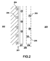
- FIG. 2 schematically illustrates an electrochemical solid/electrolyte interface.
- An electric double layer 206 may be formed at an interface 201 between an electrochemical solid 202 and an electrolyte 203.
- Charged particles, e.g. anions 204 may be located at a boundary of the electrochemical solid 202. Consequently, oppositely charged particles, e.g. cations 205, may tend to agglutinate close to the boundary of the electrochemical solid 202, thus forming the electric double layer 206.
- the electric double layer 206 comprise a first layer 207 and a second layer 208.
- the first layer 207 is composed of adsorbed cations that are attached to the interface 201.
- the second layer 208 known as diffused layer is composed of free cations.
- FIG. 3 schematically illustrates an example of a porous medium.
- the porous medium comprises an electrolyte 303 and a matrix 302, i.e. a solid portion of the porous medium.
- the matrix is essentially constituted of solid particles 307.
- Each solid particle 307 is surrounded by an electric double layer 306, due to an agglomerating of charged particles, e.g. cations 305 close to boundaries of the solid particle 307.
- a relative motion between the matrix 302 and the electrolyte 303 generates a motion of the free cations 305 of the diffused layer 306.
- the free cations 305 are moved following the single preferred direction, thus generating a current.
- the charged particles of the diffused layers 306 may be moved upon the electromagnetic field.
- the solid particles 307 are hence also moved.
- the moving of the solid particles 307 is referred to as an electromagneto-seismic effect in the present document.
- a displacing of the solid particles 307 or a flow of the electrolyte 303 is referred to as an seismo-electromagnetic effect in the present document.
- the first method is based on the fact that if periodic pressure oscillations are passed through a permeable formation, a fluid filling interconnected pores of the permeable formation is forced to move in an oscillatory manner.
- the moving of the fluid is controlled by a viscosity and an inertia of the fluid.
- An effect of the viscosity on the moving of the fluid is a function of a permeability of the formation. For a plurality of formations of different permeabilities but containing fluids of a same viscosity and inertia, a difference in phase between an electric potential and a pressure hence varies with the permeabilities of the formations.
- periodic pressure oscillations are produced in the formation. Indications are obtained of a phase displacement between the periodic pressure oscillations and any periodically varying electro-filtration potential produced by the periodic pressure oscillation.
- a periodically varying electric field is established in the formation. Indications are obtained of a phase displacement between the electric field and any periodic pressure oscillation produced by the periodically varying electric field.
- the phase displacement allows to detect the permeable formations and also to provide indications of their comparative permeabilities.
- a seismic source with two frequencies radiates radially a seismic signal within a borehole.
- a pair of electrodes above and below the seismic source allows to record a seismo-electric signal.
- the seismic source is lowered in the borehole and allows to provide a continuous logging of a formation surrounding the borehole.
- the recorded seismo-electric signal allows to provide a raw evaluating of the permeability of the formation.
- a pressure is applied to a fluid of the sample formation and an induced voltage signal is measured using a pair of measurement electrodes near the application of said pressure.
- a differential fluid pressure in the sample formation is also measured between the electrodes.
- An electric potential is also applied to the sample formation.
- An applied voltage signal is measured using a pair of measurement electrodes near the application of the electric potential.
- An induced differential fluid pressure is measured between the electrodes.
- the permeability is calculated as a simple ratio between applied quantities, i.e. the differential fluid pressure and the applied voltage signal, and induced quantities, i.e. the induced voltage signal and the induced differential fluid pressure.
- the third method may fail to provide a reliable measurement of the permeability of a formation surrounding a borehole.
- a mudcake usually covers a wall of the borehole.
- a characteristic frequency f s marks a maximal change with respect to frequency between the low frequencies and the high frequencies.
- D is a diffusion constant, the diffusion constant being characteristic of the porous medium.
- the method described above when performed over a range of frequencies, allows to determine the characteristic frequency f s .
- a thickness l cake of the mudcake may be evaluated.
- US Patent 5,841,280 to Western Atlas International, published November 24, 1998, describes a fourth method that allows to estimate a porosity of a formation surrounding a borehole.
- a transmitter imparts acoustic energy impulses into a liquid filling the wellbore.
- the acoustic energy impulses reach a wall of the wellbore and propagates in the formation.
- An acoustic response signal may be detected.
- An induced electrical voltage i.e. a seismo-electric signal, is also recorded.
- the transmitter may generate various modes of acoustic waves within the formation, e.g. longitudinal waves, shear wave, Stoneley wave.
- a Stoneley induced electrical voltage associated with a Stoneley wave has a relatively large amplitude.
- a seismo-electric Stoneley signal is synthesized from the detected acoustic energy and from an initial value of the porosity.
- a difference between the synthesized seismo-electric Stoneley signal and the recorded Stoneley induced electrical voltage is calculated.
- the initial value of the porosity is adjusted according to the difference.
- the synthesizing of the seismo-electric Stoneley signal, the calculating of the difference and the adjusting of the porosity are repeated until the difference drops below a predetermined threshold, thus allowing to estimate the porosity.
- Such an iterative inversion method may be applied to an estimating of a conductivity or a porosity of a fluid of the formation.
- the fourth method takes into consideration a propagating of a seismic wave in a porous medium of the formation.
- the frequency ⁇ /2 ⁇ is within a sonic range or within an ultrasonic range.
- Electromagnetic signals within the sonic range or within the ultrasonic range have relatively large wavelengths, which allows to keep only quasistatic terms in the Maxwell's equations.
- a coupling between an electric field and a magnetic field may be considered as low and unsteady effects in the Maxwell's equations are neglected.
- the fourth method uses the coupling equation (eq. 1) for estimating the conductivity of the fluid of the formation.
- the third method fails to take into consideration a possible propagating of a seismic wave in a matrix of the porous medium.
- Evaluating a permeability of the porous medium is hence performed in the third method by a simple ratio calculation.
- the invention provides a method according to claim 1.
- the acoustic wave and the electromagnetic exciting field are generated at a logging tool positioned within a borehole surrounded by the formation.
- an acoustic response signal is measured.
- the acoustic response signal is produced by the acoustic exciting.
- Acoustic properties of the formation are estimated from the acoustic response signal.
- An electromagnetic response signal is measured, the electromagnetic response signal being produced by the electromagnetic exciting. Electromagnetic properties of the formation are estimated from the electromagnetic response signal.
- the method further comprises selecting initial values of inversion parameters.
- a synthesis seismo-electromagnetic signal and a synthesis electromagneto-seismic signal are synthesized using the initial values of the inversion parameters.
- a first difference between the synthesis seismo-electromagnetic signal and the measured seismo-electromagnetic signal is calculated.
- a second difference between the synthesis electromagneto-seismic signal and the measured electromagneto-seismic signal is calculated.
- the values of the inversion parameters are adjusted according to the first difference and to the second difference.
- the method further comprises repeating the synthesizing using the adjusted values of the inversion parameters, the calculating of the first difference, the calculating of the second difference and the adjusting until the first difference and the second difference respectively drop below a first predetermined threshold and a second predetermined threshold.
- the inversion parameters are an electrokinetic coupling coefficient and a mobility.
- the synthesizing is simplified by synthesizing only a synthesis seismo-electromagnetic slow longitudinal signal and a synthesis electromagneto-seismic slow longitudinal signal from a mobility initial value and from an electrokinetic coupling coefficient initial value.
- the analyzing takes into consideration the propagating of the acoustic wave within the formation.
- the seismo-electromagnetic signal is a seismo-electric signal.
- the seismo-electromagnetic signal is a seismo-magnetic signal.
- the electromagneto-seismic signal is a magneto-seismic signal.
- the electromagneto-seismic signal is an electro-seismic signal.
- the logging tool is displaced along the borehole so as to provide a continuous characterizing of the formation as a function of depth.
- the invention provides a system according to claim 11.
- the electromagnetic receiver is an electric receiver allowing to measure a seismo-electric signal produced by the acoustic wave within the formation.
- the electromagnetic receiver is a magnetic receiver allowing to measure a seismo-magnetic signal produced by the acoustic wave within the formation.
- the electromagnetic emitter is an electric emitter allowing excite the formation with an electric exciting field.
- the electromagnetic emitter is a magnetic emitter allowing excite the formation with a magnetic exciting field.
- system further comprises at least one additional electromagnetic receiver and at least one additional acoustic receiver.
- FIG. 1 schematically illustrates an example of a logging operation from prior art.
- FIG. 2 schematically illustrates an electrochemical solid/electrolyte interface.
- FIG. 3 schematically illustrates an example of a porous medium.
- FIG. 4 schematically illustrates an example of a system according to the present invention.
- FIG. 5 schematically illustrates an example of a system according to a preferred embodiment of the present invention.
- FIG. 6 is a flowchart illustrating an example of a method according to an embodiment of the present invention.
- FIG. 7 illustrates an example of an algorithm for evaluating characterizing parameters of a formation surrounding a borehole, according to an embodiment of the present invention.
- Acoustically exciting a formation generates a seismo-electromagnetic signal that comprises a seismo-electric signal and/or a seismo-magnetic signal.
- An electric field or a difference of electrical potentials may be measured, thus allowing to measure the seismo-electric signal.
- a magnetic field is measured, thus allowing to measure the seismo-magnetic signal.
- both the electric field and the electromagnetic field may be measured.
- seismo-electromagnetic may designate a seismo-electric signal produced by an acoustic signal or a seismo-magnetic signal produced by the acoustic signal.
- electromagneto-seismic signal induced within the formation may be designated as "electro-seismic”. If the exciting is only magnetic, the electromagneto-seismic signal induced within the formation may be designated as "magneto-seismic”.
- electro-seismic designates either an electro-seismic signal produced by an electric excitation or a magneto-seismic signal produced by a magnetic excitation.
- Characterizing a formation surrounding a borehole e.g. evaluating a permeability of the formation or a formation factor of the formation, allows to assess a potential moving of a fluid in a porous medium. A quality and a quantity of water or oil reservoirs may subsequently be estimated.
- Evaluating the permeability also allows to determine conditions of a further oil production.
- the formation parameter allows to evaluate a quantity of oil in the formation.
- the third method from prior art involves transient electrokinetic measurements that are rendered difficult by a mudcake of the borehole.
- the second method and the fourth method from prior art provide a measurement of a seismo-electric signal produced by a seismic signal. Such a measurement allows to evaluate a porosity of the formation, as performed in the fourth method.
- the seismic signals are generated at multiple frequencies and amplitudes of the seismo-electric signals produced by the seismic signals are measured at each frequency, which allows to evaluate the permeability of the formation.
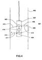
- FIG. 4 schematically illustrates an example of a system according to the present invention.
- Acoustic waves and electromagnetic fields are represented on FIG. 4 by arrows 408, 409, 410, 411, 412 and 413.
- the system allows to characterize a formation 401.
- the formation 401 surrounds a borehole 402.
- the system may comprise a logging tool 407 to be lowered into the borehole 402.
- the system may be located at a surface of the formation 401.
- An acoustic emitter 403 allows to excite the formation 401 with an acoustic wave 408 propagating within the formation 401.
- a seismo-electromagnetic signal 409 produced by the acoustic wave 408 within the formation 401 is measured using an electromagnetic receiver 404.
- An electromagnetic emitter 404 allows to excite the formation 401 with an electromagnetic exciting field 411.
- An electromagneto-seismic signal 413 produced by the electromagnetic exciting field 411 within the formation 401 is measured using an acoustic receiver 403.
- Processing means 414 allow to analyze the measured seismo-electromagnetic signal 409 and the measured electromagneto-seismic signal 413 so as to evaluate characterizing parameters of the formation 401.
- the processing means 414 may be part of the logging tool 407 as represented in FIG. 4 . Alternatively, the processing means are located at a distinct location, e.g. at surface.
- a method according to the present invention allows to provide a more accurate evaluating of a permeability of the formation 401 than the second method and the fourth method from prior art.
- the seismo-electromagnetic signal 409 is produced by the acoustic wave 408 that propagates within the formation 401.
- an applied pressure diffuses into a fluid of the formation.
- the permeability is evaluated by a simple ratio calculation based on a streaming model that fails to take into consideration a propagating of an acoustic wave in a porous medium.
- the method according to the present invention allows to provide a more accurate evaluating of the permeability of the formation 401.
- the method according to the present invention may provide a faster evaluating of the permeability or the other characterizing parameters than the third method from prior art.
- the logging tool 407 may preferably be spaced from walls of the borehole 402 and may be easily displaced so as to allow a continuous characterizing of the formation as a function of depth.
- the logging tool may contact the walls of the borehole.
- the acoustic emitter 403 and the acoustic receiver 403 may be a single device, as represented in FIG. 4 . However, the acoustic emitter 403 and the acoustic receiver 403 may also be distinct devices.
- One or more additional acoustic receiver(s) may be provided.
- the acoustic receiver and the additional acoustic receivers may form an array of acoustic receivers.
- the electromagnetic emitter 404 and the electromagnetic receiver 404 may be a single device, as represented in FIG. 4 . However, the electromagnetic emitter 404 and the electromagnetic receiver 404 may be distinct devices.
- the system may further comprise one or more additional electromagnetic receiver(s) (not represented on FIG. 4 ).
- the electromagnetic receiver and the additional electromagnetic receivers may form an array of acoustic receivers.
- the acoustic emitter 403 and the electromagnetic emitter 404 are located onto the logging tool 407.
- the acoustic wave 408 and the electromagnetic exciting field 411 are hence generated at the logging tool 407.
- the measuring of the seismo-electromagnetic signal may be performed by measuring an electric field only, i.e. the seismo-electromagnetic signal is a seismo-electric signal.
- the measuring of the seismo-electromagnetic signal may be performed by measuring a magnetic field only, i.e. the seismo-electromagnetic signal is a seismo-magnetic signal.
- both the electric field and the magnetic field are measured.
- the exciting of the formation with the electromagnetic exciting field is only electric: an electro-seismic signal is subsequently measured.
- the exciting of the formation with the electromagnetic exciting field is only magnetic and a magneto-seismic signal is measured.
- the formation is excited with both an electric exciting field and a magnetic exciting field, either simultaneously or not. In this latter case, more signals may be measured, thus allowing to insure a reliable evaluating of the characterizing parameters.
- an acoustic response signal 410 is measured after the exciting of the formation 401 with the acoustic wave 408.
- the acoustic response signal 412 is produced by the acoustic exciting.
- the acoustic response signal 410 may be measured at the acoustic receiver 403, as represented in FIG. 4 , or at any other receiver allowing to measure an acoustic signal.
- an electromagnetic response signal 412 may be measured after the exciting of the formation with the electromagnetic exciting field 411.
- the electromagnetic response signal 412 is produced by the electromagnetic exciting.
- the electromagnetic response signal 412 may be measured at the electromagnetic receiver 404, as represented in FIG. 4 , or at any other receiver allowing to measure an electromagnetic signal.
- FIG. 5 schematically illustrates an example of a system according to a preferred embodiment of the present invention.
- the system allows to characterize a formation 501 surrounding a borehole 502.
- the system comprises a logging tool 507 to be lowered into the borehole 502.
- An acoustic emitter 503 and an electromagnetic emitter 504 are located onto the logging tool 507.
- the acoustic emitter 503 and the electromagnetic emitter 504 respectively allow to excite the formation 501 with an acoustic wave (not represented on FIG. 5 ) and an electromagnetic exciting field (not represented on FIG. 5 ).
- the acoustic exciting and the electromagnetic exciting are not performed simultaneously.
- the system further comprises an array of acoustic receivers 505 and an array of electromagnetic receivers 506 disposed onto the logging tool 507.
- Various modes of the acoustic wave may propagate within the formation, e.g. a fast longitudinal wave or a slow longitudinal wave, a shear wave, a Stoneley wave.
- the array of acoustic receivers 505 and the array of electromagnetic receivers 506 allow to properly measure signals providing from a desired mode.
- acoustic properties of the formation 501 may be easily determined at a further analyzing, e.g. by a simple ratio between a time of detection and a distance between two acoustic receivers 505.
- electromagnetic properties of the formation 501 may be easily determined due to the array of electromagnetic receivers 506.
- electromagnetic receiver we designate either an electric receiver or a magnetic receiver.
- the electric receiver and the magnetic receiver respectively allow to measure a seismo-electric signal and a seismo-magnetic signal produced by the acoustic wave within the formation.
- the electromagnetic receivers 506 may for example be electrodes, coils, magnetometers etc. depending on which field (electric or magnetic) is to be measured.
- the electromagnetic receivers 506 are relatively close to a wall of the borehole 502 so as to so as measure signals having a relatively high amplitude.
- the electromagnetic receivers 506 may also be relatively close to the electromagnetic emitter 504: typically a distance between each electromagnetic receiver 506 and the electromagnetic emitter 504 is relatively small compared to a wavelength of the acoustic wave.
- the acoustic receivers 505 may for example be made of a piezoelectric material. However, any other receiver allowing to measure a mechanical signal, e.g. a pressure field or particles velocities, may be used. Preferably the acoustic receivers 505 are relatively close to a wall of the borehole 502 so as to measure signals having a relatively high amplitude.
- the electromagnetic receivers 506 may either allow measurements relative to a single axis, to two axes or to three axes.
- the acoustic receivers 505 may either allow measurements relative to a single axis, to two axes or to three axes.
- electromagnetic emitter we designate either an electric emitter or a magnetic emitter.
- the electric emitter allows to excite the formation with an electric exciting field and the magnetic emitter allows to excite the formation with a magnetic exciting field.
- electroconductive exciting field hence designate either the electric exciting field, the magnetic exciting field or a combination.
- a frequency range of the electromagnetic exciting field is such that a coupling between an electric field and a magnetic field in Maxwell's equations may be neglected: the electromagnetic exciting field is considered to be either the electric exciting field or the magnetic exciting field.
- the electromagnetic emitter 504 may for example be an electrode, a coil, or any other device allowing to create an electric field or a magnetic field.
- the acoustic emitter 503 may be a transducer, or any device allowing to excite the formation 501 with an acoustic wave.
- the acoustic emitter 503 may be a monopole, a dipole, or a multipole. The dipole allows for example to excite the formation 501 with a shear acoustic wave.
- the electromagnetic emitter 504 and the acoustic emitter 503 have a same frequency content.
- the acoustic wave and the electromagnetic exciting field have a same frequency so as to allow a further analysis of measured signals.
- the frequency is below a critical frequency of the formation 501. Typically, the frequency is below 5 kHz.
- the acoustic exciting and the electromagnetic exciting allow to measure four signals (not represented on FIG. 5 ) :
- the processing means 508 may be a computer located at surface, a processor within the logging tool, or any other device allowing to evaluate the characterizing parameters.
- FIG. 6 is a flowchart illustrating an example of a method according to an embodiment of the present invention. The method allows to characterize a formation surrounding a borehole.
- the method comprises exciting a formation with an acoustic wave propagating into the formation (box 61).
- a seismo-electromagnetic signal produced by the acoustic wave within the formation is subsequently measured (box 62).
- An acoustic response signal corresponding to the acoustic wave is also measured (box 63).
- the measuring of the acoustic response signal (box 63) may be performed before the measuring of the seismo-electromagnetic signal (box 62), after the measuring of the seismo-electromagnetic signal (box 62), or simultaneously.
- the method further comprises exciting a formation with an electromagnetic exciting field (box 64).
- An electromagneto-seismic signal produced by the electromagnetic exciting field within the formation is subsequently measured (box 65).
- An electromagnetic response signal corresponding to the electromagnetic exciting field is also measured (box 66).
- the measuring of the electromagnetic response signal (box 66) may be performed before the measuring of the electromagneto-seismic signal (box 65), after the measuring of the electromagneto-seismic signal (box 62), or simultaneously.
- the exciting with the acoustic wave (box 61), the measuring of the seismo-electromagnetic signal (box 62) and the measuring of the electromagnetic response signal (box 63) may be performed after the exciting with the electromagnetic exciting field (box 64) and subsequent measuring steps (boxes 65 and 66). More generally, the exciting steps (boxes 61 and 64) and the measuring steps (boxes 62, 63, 65 and 66) may be performed following any order that allows proper measurements.
- an analysis may be performed so as to evaluate characterizing parameters of the formation.
- the acoustic response signal produced by the acoustic exciting (box 61) is an acoustic wave reflected at the formation or having traveled through the formation. Acoustic properties of the formation, e.g. velocities of various modes of acoustic waves, an acoustic impedance may be estimated from the acoustic response signal (box 67).
- the estimating of the acoustic properties may for example be performed following an iterative inversion method: an initial value of the acoustic properties is selected. A synthesis acoustic response signal is synthesized from the initial value of the acoustic properties. An acoustic difference between the synthesis acoustic response signal and the measured acoustic response signal is calculated. The value of the acoustic properties is adjusted according to the acoustic difference. The synthesizing, the calculating of the acoustic difference and the adjusting may be repeated until the acoustic difference drops below a predetermined acoustic threshold.
- the electromagnetic response signal produced by the electromagnetic exciting (box 64) is sensitive to electromagnetic properties of the formation. Electromagnetic properties of the formation, e.g. an overall electrical conductivity ⁇ ( ⁇ ) or dielectric properties, may be estimated from the electromagnetic response signal (box 68).
- the estimating of the electromagnetic properties may for example be performed following an iterative inversion method: an initial value of the electromagnetic properties is selected. A synthesis electromagnetic response signal is synthesized from the initial value of the electromagnetic properties. An electromagnetic difference between the synthesis electromagnetic response signal and the measured electromagnetic response signal is calculated. The value of the electromagnetic properties is adjusted according to the electromagnetic difference. The synthesizing, the calculating of the electromagnetic difference and the adjusting may be repeated until the electromagnetic difference drops below a predetermined electromagnetic threshold.
- the estimating of the acoustic properties (box 67) and the estimating of the electromagnetic properties (box 68) may be performed with a method distinct from the iterative inversion method.
- the acoustic properties e.g. a value of the velocities for longitudinal waves and shear waves, and/or the electromagnetic properties may be estimated from another logging measurement.
- the estimating of the acoustic properties may also be performed after the estimating of the electromagnetic properties (box 68), or simultaneously.
- the estimating of the acoustic properties (box 67) and the estimating of the electromagnetic properties (box 68) allow to evaluate the characterizing parameters (box 69).
- the characterizing parameters may for example be an electrokinetic coupling coefficient L, a formation factor F of the formation and a mobility, i.e. a ratio k / ⁇ of a permeability of the formation over a viscosity of a fluid within the formation.
- the permeability k may easily be deduced from the ratio kl ⁇ and from the viscosity ⁇ .
- the electrokinetic coupling coefficient L and the permeability k generally vary with a frequency of the acoustic wave or of the electromagnetic exciting field.
- FIG. 7 illustrates an example of an algorithm for evaluating characterizing parameters of a formation surrounding a borehole, according to an embodiment of the present invention.
- the algorithm of FIG. 7 may be executed by processing means of a system according to the present invention.
- Initial values of inversion parameters are selected (box 71).
- the inversion parameters are an electrokinetic coupling coefficient L and a mobility, i.e. a ratio k / ⁇ of a permeability of the formation over a viscosity of a fluid within the formation.
- the inversion parameters may be any other parameter involved in equations relating to electrokinetic phenomena.
- a synthesis seismo-electromagnetic signal and a synthesis electromagneto-seismic signal are synthesized (box 72) using the initial values of the electrokinetic coupling coefficient L, i.e. a coupling initial value, and the initial values of the ratio k / ⁇ , i.e. a mobility initial value.
- a first difference D1 is calculated between the synthesis seismo-electromagnetic signal and a measured seismo-electromagnetic signal and a second difference D2 is calculated between the synthesis electromagneto-seismic signal and a measured electromagneto-seismic signal (box 73).
- the calculating may for example involve a least squares method.
- the first difference D1 is compared to a first predetermined threshold T1 and the second difference D2 is compared to a second predetermined threshold T2 (box 74). If the first difference D1 and the second difference D2 are respectively below the first predetermined threshold T1 and the second predetermined threshold T2, it is considered that the values of the inversion parameters are properly estimated.
- the values of the inversion parameters i.e. the ratio k / ⁇ of the permeability of the formation over the viscosity and the value of the electrokinetic coupling coefficient L are adjusted according to the first difference and to the second difference (box 75).
- the synthesizing of the synthesis seismo-electromagnetic signal and of the synthesis electromagneto-seismic signal, the calculating of the first difference and of the second difference, and the adjusting are repeated until the first difference D1 and the second difference D2 drop respectively below the first predetermined threshold T1 and the second predetermined threshold T2.
- the synthesizing of the synthesis seismo-electromagnetic signal and of the synthesis electromagneto-seismic signal, the calculating of the first difference and of the second difference, and the adjusting may be performed following any order allowing a proper estimating of the inversion parameters.
- a value of a formation factor F of the formation may be determined (box 76).
- the determining of the formation factor may require to estimate the electrokinetic coupling coefficient L( ⁇ ) at different angular frequencies.
- the algorithm for evaluating the inversion parameters may be applied to the seismo-electromagnetic signal and to the electromagneto-seismic signal simultaneously, as represented in FIG. 7 .
- the seismo-electromagnetic signal and the electromagneto-seismic signal are inverted simultaneously to evaluate the electrokinetic coupling coefficient L and the mobility k / ⁇ .
- one or more steps of the algorithm may be applied to a single signal and be subsequently repeated.
- the whole algorithm may even be applied to the electromagneto-seismic signal first, and then to the seismo-electromagnetic signal, or vice-versa, before an additional step in which the electrokinetic coupling coefficient L and the mobility k / ⁇ are estimated from intermediate parameters.
- the synthesizing takes into consideration a propagating of an acoustic wave in the formation.
- the propagating of the acoustic wave in a matrix of a porous medium may be considered.
- the synthesizing is based on Pride's coupling equations (eq. 1 and 2).
- acoustic waves are generated within the formation, e.g. a fast longitudinal acoustic wave, a slow longitudinal acoustic wave, a shear acoustic wave, a Stoneley acoustic wave.
- a fast longitudinal acoustic wave e.g. a fast longitudinal acoustic wave, a slow longitudinal acoustic wave, a shear acoustic wave, a Stoneley acoustic wave.
- the fast longitudinal acoustic wave and the slow longitudinal acoustic wave indeed fail to generate a magnetic field and the shear acoustic wave fails to generate an electric field.
- an electro-seismic fast longitudinal signal, an electro-seismic slow longitudinal signal and an electro-seismic Stoneley signal are produced within the formation.
- the synthesizing of a complete synthesis seismo-electromagnetic signal involves relatively complex calculation when based on Pride's coupling equation (eq. 1).
- the synthesizing may be simplified by considering only a single mode of acoustic wave, e.g. the slow longitudinal acoustic wave.
- a plurality of well-chosen modes of acoustic waves is considered, e.g. the slow longitudinal acoustic wave and the fast longitudinal acoustic wave.
- a plurality of modes of acoustic waves may be separately considered, thus involving a plurality of relatively simplified calculations.
- the synthesizing of a complete synthesis electromagneto-seismic signal involves relatively complex calculation when based on Pride's second coupling equation (eq. 2).
- the synthesizing may be simplified by considering only a single mode of electromagneto-seismic signal, e.g. the electro-seismic slow longitudinal signal.
- a plurality of well-chosen modes of electromagneto-seismic signals is considered, e.g. the electro-seismic slow longitudinal signal and the electro-seismic fast longitudinal signal.
- the slow longitudinal acoustic wave has a relatively high sensitivity to the mobility. In the case of an acoustic excitation, the slow longitudinal acoustic wave hence is preferably considered.
- a synthesis seismo-electromagnetic slow longitudinal signal is synthesized from the mobility initial value and from the coupling initial value.
- the high sensitivity to the mobility of the slow longitudinal acoustic wave is well known from the art.
- the method of the present invention considers the seismo-electromagnetic slow longitudinal signal associated to the slow longitudinal acoustic wave to provide information about the mobility. Unlike the slow longitudinal acoustic wave which is relatively difficult to measure directly, the seismo-electromagnetic slow longitudinal signal may be measured relatively easily.
- the first difference is calculated between the synthesis seismo-electromagnetic slow longitudinal signal and a slow longitudinal portion of the measured seismo-electromagnetic signal.
- the second difference is calculated between the synthesis electromagneto-seismic slow longitudinal signal and a slow longitudinal portion of the measured electromagneto-seismic signal.
- the first difference and the second difference are subsequently compared to predetermined thresholds, as described in FIG. 7 .
- the values of the inversion parameters i.e. the permeability of the formation over the viscosity and the value of the electrokinetic coupling coefficient are adjusted according to the first difference and to the second difference.
- the synthesizing steps, the calculating steps and the adjusting steps may be repeated, thus providing an iterative inversion method for characterizing the formation.
- the fast longitudinal wave, the Stoneley wave and the shear wave may also be considered, either alone or in combination with the slow longitudinal wave.
- a distinct method may be used to analyze the seismo-electromagnetic signal and the electromagneto-seismic signal.
- spontaneous and acoustic may be used indifferently in the present description: both terms relates to a mechanical phenomenon.
Landscapes
- Life Sciences & Earth Sciences (AREA)
- Physics & Mathematics (AREA)
- Engineering & Computer Science (AREA)
- General Life Sciences & Earth Sciences (AREA)
- General Physics & Mathematics (AREA)
- Geophysics (AREA)
- Remote Sensing (AREA)
- Chemical Kinetics & Catalysis (AREA)
- Electrochemistry (AREA)
- Electromagnetism (AREA)
- Chemical & Material Sciences (AREA)
- Environmental & Geological Engineering (AREA)
- Geology (AREA)
- Geophysics And Detection Of Objects (AREA)
- Investigating Or Analyzing Materials By The Use Of Ultrasonic Waves (AREA)
Claims (16)
- Procédé de caractérisation d'une formation (401 ; 501) avec un outil de diagraphie (407 ; 507) positionné à l'intérieur d'un trou de sonde (402 ; 502) entouré par la formation (401 ; 501), caractérisé en ce que le procédé comprend :l'excitation (61) avec l'outil de diagraphie (407 ; 507) de la formation (401 ; 501) avec une onde acoustique se propageant dans la formation (401 ; 501) ;la mesure (62) d'un signal sismo-électromagnétique produit par l'onde acoustique à l'intérieur de la formation (401 ; 501) ;l'excitation (64) avec l'outil de diagraphie (407 ; 507) de la formation (401 ; 501) avec un champ électromagnétique d'excitation ;la mesure (65) d'un signal électromagnéto-sismique produit par le champ électromagnétique d'excitation à l'intérieur de la formation (401 ; 501) ;l'analyse (69) du signal sismo-électromagnétique mesuré et du signal électromagnéto-sismique mesuré pour évaluer des paramètres de caractérisation de la formation (401 ; 501).
- Procédé selon la revendication 1, comprenant en outré :la mesure (63) d'un signal de réponse acoustique, le signal de réponse acoustique étant produit par l'excitation acoustique ;l'estimation (67) de propriétés acoustiques de la formation (401 ; 501) à partir du signal de réponse acoustique ;la mesure (66) d'un signal de réponse électromagnétique, le signal de réponse électromagnétique étant produit par l'excitation électromagnétique ;l'estimation (68) de propriétés électromagnétiques de la formation (401 ; 501) à partir du signal de réponse électromagnétique.
- Procédé selon la revendication 2, comprenant en outré :la sélection (71) de valeurs initiales de paramètres d'inversionla synthèse (72) d'un signal sismo-électromagnétique de synthèse et d'un signal électromagnéto-sismique de synthèse au moyen des valeurs initiales des paramètres d'inversion ;le calcul (73) d'une première différence entre le signal sismo-électromagnétique de synthèse et le signal sismo-électromagnétique mesuré ;le calcul (73) d'une seconde différence entre le signal électromagnéto-sismique de synthèse et le signal électromagnéto-sismique mesuré ;l'ajustement (75) des valeurs des paramètres d'inversion selon la première différence et la seconde différence ;la répétition de la synthèse au moyen des valeurs ajustées des paramètres d'inversion, le calcul de la première différence, le calcul de la seconde différence et l'ajustement jusqu'à ce que la première différence et la seconde différence chutent respectivement en dessous d'un premier seuil prédéterminé et d'un second seuil prédéterminé.
- Procédé selon la revendication 3, dans lequel :les paramètres d'inversion sont un coefficient de couplage électrocinétique et une mobilité ;la synthèse est simplifiée en synthétisant seulement un signal sismo-électromagnétique longitudinal lent de synthèse et un signal électromagnéto-sismique longitudinal lent de synthèse à partir d'une valeur initiale de mobilité et à partir d'une valeur initiale de coefficient de couplage électrocinétique.
- Procédé selon l'une quelconque des revendications 1 à 4, dans lequell'analyse prend en compte la propagation de l'onde acoustique (408) à l'intérieur de la formation (401, 501).
- Procédé selon l'une quelconque des revendications 1 à 5, dans lequel :le signal sismo-électromagnétique (409) est un signal sismo-électrique.
- Procédé selon l'une quelconque des revendications 1 à 5, dans lequel :le signal sismo-électromagnétique (409) est un signal sismo-magnétique.
- Procédé selon l'une quelconque des revendications 1 à 7, dans lequelle signal électromagnéto-sismique (413) est un signal magnéto-sismique.
- Procédé selon l'une quelconque des revendications 1 à 7, dans lequelle signal électromagnéto-sismique (413) est un signal électro-sismique.
- Procédé selon l'une quelconque des revendications 1 à 9, comprenant en outré :le déplacement de l'outil de diagraphie (407 ; 507) le long du trou de sonde (402 ; 502) afin de fournir une caractérisation continue de la formation (401 ; 501) en fonction de la profondeur.
- Système de caractérisation d'une formation (401) entourant un trou de sonde (402), caractérisé en ce que le système comprend :un outil de diagraphie (407) à descendre dans le trou de sonde ;un émetteur acoustique (403) situé sur l'outil de diagraphie, l'émetteur acoustique permettant l'excitation de la formation avec une onde acoustique (408) se propageant à l'intérieur de la formation ;un récepteur électromagnétique (404) pour mesurer un signal sismo-électromagnétique (409) produit par l'onde acoustique à l'intérieur de la formation ;un émetteur électromagnétique (404) situé sur l'outil de diagraphie, l'émetteur électromagnétique permettant l'excitation de la formation avec un champ électromagnétique d'excitation (411) ;un récepteur acoustique (403) pour mesurer un signal électromagnéto-sismique (413) produit par le champ électromagnétique d'excitation à l'intérieur de la formation ;des moyens de traitement (414) pour analyser le signal sismo-électromagnétique mesuré et le signal électromagnéto-sismique mesuré afin d'évaluer des paramètres de caractérisation de la formation.
- Système selon la revendication 11, dans lequel :le récepteur électromagnétique (404) est un récepteur électrique permettant la mesure d'un signal sismo-électrique (409) produit par l'onde acoustique (408) à l'intérieur de la formation (401).
- Système selon la revendication 11, dans lequel :le récepteur électromagnétique (504) est un récepteur magnétique permettant la mesure d'un signal sismo-électrique produit par l'onde acoustique à l'intérieur de la formation (501).
- Système selon l'une quelconque des revendications 11 à 13, dans lequel :l'émetteur électromagnétique (404) est un émetteur électrique permettant l'excitation de la formation (401) avec un champ électrique d'excitation.
- Système selon l'une quelconque des revendications 11 à 13, dans lequel :l'émetteur électromagnétique (504) est un émetteur magnétique permettant l'excitation de la formation (501) avec un champ magnétique d'excitation.
- Système selon la revendication 11 ou 12, comprenant en outré :au moins un récepteur électromagnétique (506) supplémentaire ;au moins un récepteur acoustique (505) supplémentaire.
Priority Applications (5)
| Application Number | Priority Date | Filing Date | Title |
|---|---|---|---|
| AT04290707T ATE418081T1 (de) | 2004-03-16 | 2004-03-16 | Charakterisierung der eigenschaften geologischer formationen durch kombinierte akustische und elektromagnetische messungen |
| EP04290707A EP1577683B1 (fr) | 2004-03-16 | 2004-03-16 | Caractérisation des propriétés d'une formation géologique par mesures acoustiques et électromagnétiques couplées |
| DE602004018454T DE602004018454D1 (de) | 2004-03-16 | 2004-03-16 | Charakterisierung der Eigenschaften geologischer Formationen durch kombinierte akustische und elektromagnetische Messungen |
| PCT/EP2005/002469 WO2005096023A1 (fr) | 2004-03-16 | 2005-03-07 | Proprietes de caracterisation d'une formation geologique au moyen de mesures acoustiques et electromagnetiques couplees |
| US10/598,912 US20070150200A1 (en) | 2004-03-16 | 2005-03-07 | Characterizing properties of a geological formation by coupled acoustic and electromagnetic measurements |
Applications Claiming Priority (1)
| Application Number | Priority Date | Filing Date | Title |
|---|---|---|---|
| EP04290707A EP1577683B1 (fr) | 2004-03-16 | 2004-03-16 | Caractérisation des propriétés d'une formation géologique par mesures acoustiques et électromagnétiques couplées |
Publications (2)
| Publication Number | Publication Date |
|---|---|
| EP1577683A1 EP1577683A1 (fr) | 2005-09-21 |
| EP1577683B1 true EP1577683B1 (fr) | 2008-12-17 |
Family
ID=34833788
Family Applications (1)
| Application Number | Title | Priority Date | Filing Date |
|---|---|---|---|
| EP04290707A Expired - Lifetime EP1577683B1 (fr) | 2004-03-16 | 2004-03-16 | Caractérisation des propriétés d'une formation géologique par mesures acoustiques et électromagnétiques couplées |
Country Status (5)
| Country | Link |
|---|---|
| US (1) | US20070150200A1 (fr) |
| EP (1) | EP1577683B1 (fr) |
| AT (1) | ATE418081T1 (fr) |
| DE (1) | DE602004018454D1 (fr) |
| WO (1) | WO2005096023A1 (fr) |
Families Citing this family (16)
| Publication number | Priority date | Publication date | Assignee | Title |
|---|---|---|---|---|
| CA2544457C (fr) * | 2006-04-21 | 2009-07-07 | Mostar Directional Technologies Inc. | Systeme et methode de telemesure de fond de trou |
| BRPI0711383A2 (pt) * | 2006-05-10 | 2011-11-22 | Baker Hughes Inc | utilização de medições de múltiplos componentes no delineamento de geologia de sedimentos de águas profundas |
| WO2009091283A2 (fr) * | 2006-06-22 | 2009-07-23 | Schlumberger Canada Limited | Procédé de détermination de la perméabilité d'une formation saturée |
| US7813219B2 (en) * | 2006-11-29 | 2010-10-12 | Baker Hughes Incorporated | Electro-magnetic acoustic measurements combined with acoustic wave analysis |
| RU2419819C2 (ru) * | 2007-02-06 | 2011-05-27 | Шлюмберже Текнолоджи Б.В. | Способ, система и скважинный прибор для оценки проницаемости пласта |
| US7944211B2 (en) * | 2007-12-27 | 2011-05-17 | Schlumberger Technology Corporation | Characterization of formations using electrokinetic measurements |
| US8490693B2 (en) * | 2009-02-17 | 2013-07-23 | Schlumberger Technology Corporation | Determining fracture orientation using wellbore acoustic radial profiles |
| US20100213943A1 (en) * | 2009-02-23 | 2010-08-26 | Baker Hughes Incorporated | Method for accentuating signal from ahead of the bit |
| CA2708894A1 (fr) | 2009-07-17 | 2011-01-17 | Baker Hughes Incorporated | Ondes radiales de puits de forage et ondes de stoneley permettant de mesurer la permeabilite d'une formation et la constante electroacoustique |
| GB201017701D0 (en) | 2010-10-20 | 2010-12-01 | Emon Uk Ltd | Methods and apparatus for geophysical prospecting to detect bodies of fluids in underground porous structures |
| BR112014007287A2 (pt) * | 2011-09-27 | 2017-04-18 | Halliburton Energy Services Inc | método e sistema para realizar uma operação de perfuração, e, dispositivo de armazenamento legível por máquina |
| WO2014193382A1 (fr) * | 2013-05-30 | 2014-12-04 | Halliburton Energy Services, Inc. | Appareil de détection électromagnétique pour l'acoustique de forage |
| US9651707B2 (en) | 2013-06-28 | 2017-05-16 | Cgg Services Sas | Methods and systems for joint seismic and electromagnetic data recording |
| US9835609B2 (en) | 2015-03-25 | 2017-12-05 | Chevron U.S.A. Inc. | System and method for determining fluid viscosity of a fluid in a rock formation |
| FR3060636B1 (fr) * | 2016-12-20 | 2019-05-24 | IFP Energies Nouvelles | Procede de surveillance de la salinite au sein d'une formation souterraine |
| US11215035B2 (en) | 2018-02-07 | 2022-01-04 | Schlumberger Technology Corporation | Method to predict reservoir formation permeability using combined acoustic and multi-frequency dielectric measurements |
Family Cites Families (21)
| Publication number | Priority date | Publication date | Assignee | Title |
|---|---|---|---|---|
| US2814017A (en) * | 1953-05-26 | 1957-11-19 | Schlumberger Well Surv Corp | Methods for logging the formations traversed by a borehole |
| EP0275206A3 (fr) * | 1987-01-16 | 1989-11-23 | Gec-Marconi Limited | Diminution du bruit par courant |
| US4964101A (en) * | 1989-03-23 | 1990-10-16 | Schlumberger Technology Corp. | Method for determining fluid mobility characteristics of earth formations |
| US5001675A (en) * | 1989-09-13 | 1991-03-19 | Teleco Oilfield Services Inc. | Phase and amplitude calibration system for electromagnetic propagation based earth formation evaluation instruments |
| US5417104A (en) * | 1993-05-28 | 1995-05-23 | Gas Research Institute | Determination of permeability of porous media by streaming potential and electro-osmotic coefficients |
| NO314646B1 (no) * | 1994-08-15 | 2003-04-22 | Western Atlas Int Inc | Transient-elektromagnetisk måleverktöy og fremgangsmåte for bruk i en brönn |
| US5732776A (en) * | 1995-02-09 | 1998-03-31 | Baker Hughes Incorporated | Downhole production well control system and method |
| GB9521171D0 (en) * | 1995-10-17 | 1995-12-20 | Millar John W A | Detection method |
| US5809458A (en) * | 1996-09-05 | 1998-09-15 | Western Atlas International, Inc. | Method of simulating the response of a through-casing electrical resistivity well logging instrument and its application to determining resistivity of earth formations |
| US5841280A (en) * | 1997-06-24 | 1998-11-24 | Western Atlas International, Inc. | Apparatus and method for combined acoustic and seismoelectric logging measurements |
| US6177882B1 (en) * | 1997-12-01 | 2001-01-23 | Halliburton Energy Services, Inc. | Electromagnetic-to-acoustic and acoustic-to-electromagnetic repeaters and methods for use of same |
| US6018501A (en) * | 1997-12-10 | 2000-01-25 | Halliburton Energy Services, Inc. | Subsea repeater and method for use of the same |
| US6351991B1 (en) * | 2000-06-05 | 2002-03-05 | Schlumberger Technology Corporation | Determining stress parameters of formations from multi-mode velocity data |
| US6585044B2 (en) * | 2000-09-20 | 2003-07-01 | Halliburton Energy Services, Inc. | Method, system and tool for reservoir evaluation and well testing during drilling operations |
| US6470275B1 (en) * | 2000-11-14 | 2002-10-22 | Baker Hughes Incorporated | Adaptive filtering with reference accelerometer for cancellation of tool-mode signal in MWD applications |
| US6807487B2 (en) * | 2001-05-11 | 2004-10-19 | Nonlinear Seismic Imaging, Inc. | Mapping permeable reservoir formations by measuring the elastic nonlinear interactions of a seismic wave as it propagates through the reservoir rock matrix and its pore fluids |
| US6541975B2 (en) * | 2001-08-23 | 2003-04-01 | Kjt Enterprises, Inc. | Integrated borehole system for reservoir detection and monitoring |
| US6909667B2 (en) * | 2002-02-13 | 2005-06-21 | Halliburton Energy Services, Inc. | Dual channel downhole telemetry |
| FR2836557B1 (fr) * | 2002-02-28 | 2004-05-28 | Schlumberger Services Petrol | Procede et dispositif de prospection geophysique d'une formation geologique poreuse contenant au moins un fluide electrolyque |
| US6944548B2 (en) * | 2002-12-30 | 2005-09-13 | Schlumberger Technology Corporation | Formation evaluation through azimuthal measurements |
| US7043370B2 (en) * | 2003-08-29 | 2006-05-09 | Baker Hughes Incorporated | Real time processing of multicomponent induction tool data in highly deviated and horizontal wells |
-
2004
- 2004-03-16 EP EP04290707A patent/EP1577683B1/fr not_active Expired - Lifetime
- 2004-03-16 AT AT04290707T patent/ATE418081T1/de not_active IP Right Cessation
- 2004-03-16 DE DE602004018454T patent/DE602004018454D1/de not_active Expired - Fee Related
-
2005
- 2005-03-07 US US10/598,912 patent/US20070150200A1/en not_active Abandoned
- 2005-03-07 WO PCT/EP2005/002469 patent/WO2005096023A1/fr active Application Filing
Also Published As
| Publication number | Publication date |
|---|---|
| EP1577683A1 (fr) | 2005-09-21 |
| WO2005096023A1 (fr) | 2005-10-13 |
| ATE418081T1 (de) | 2009-01-15 |
| DE602004018454D1 (de) | 2009-01-29 |
| US20070150200A1 (en) | 2007-06-28 |
Similar Documents
| Publication | Publication Date | Title |
|---|---|---|
| US20070150200A1 (en) | Characterizing properties of a geological formation by coupled acoustic and electromagnetic measurements | |
| US8682587B2 (en) | Method and apparatus for determining the permeability of earth formations | |
| CA2235263C (fr) | Appareil et methode de mesures combinees de donnees acoustiques et sismoelectriques | |
| Mikhailov et al. | Using borehole electroseismic measurements to detect and characterize fractured (permeable) zones | |
| US7617050B2 (en) | Method for quantifying resistivity and hydrocarbon saturation in thin bed formations | |
| US20110019500A1 (en) | Method, system and logging tool for estimating permeability of a formation | |
| Lee | Models for gas hydrate-bearing sediments inferred from hydraulic permeability and elastic velocities | |
| US20210255359A1 (en) | Method for estimating rock brittleness from well-log data | |
| US8630146B2 (en) | Method and apparatus for estimating formation permeability and electroacoustic constant of an electrolyte-saturated multi-layered rock taking into account osmosis | |
| Peng et al. | Experimental study of the seismoelectric interface response in wedge and cavity models | |
| US7944211B2 (en) | Characterization of formations using electrokinetic measurements | |
| US20190242221A1 (en) | Method to predict reservoir formation permeability using combined acoustic and multi-frequency dielectric measurements | |
| US7259564B2 (en) | Method and device for determining the position of an interface in relation to a bore hole | |
| Wang et al. | Measurements of the seismoelectric responses in a synthetic porous rock | |
| US7679992B2 (en) | Wettability from electro-kinetic and electro-osmosis measurements | |
| EP1619520A1 (fr) | Procédé et appareil permettant d'estimer la distribution de la perméabilité concernant les essais de puits | |
| US9366777B2 (en) | Measurement of permeability in borehole in the presence of mudcake | |
| US8344726B2 (en) | Acoustic modified NMR (AMNMR) | |
| Jouniaux et al. | Seismo-electrics, electro-seismics, and seismo-magnetics for earth sciences | |
| US7150188B2 (en) | Non-invasive measurement of fluid-pressure diffusivity using electro-osmosis | |
| Zhu et al. | Borehole Model in a Horizontally Layered Strata | |
| Zhu et al. | Seismoelectric measurements in a fractured borehole model | |
| SU1350339A1 (ru) | Способ исследовани пластов-коллекторов | |
| RU2213360C1 (ru) | Способ оценки типа жидкости, насыщающей горные породы | |
| NO20191505A1 (en) | Method for estimating rock brittleness from well-log data |
Legal Events
| Date | Code | Title | Description |
|---|---|---|---|
| PUAI | Public reference made under article 153(3) epc to a published international application that has entered the european phase |
Free format text: ORIGINAL CODE: 0009012 |
|
| AK | Designated contracting states |
Kind code of ref document: A1 Designated state(s): AT BE BG CH CY CZ DE DK EE ES FI FR GB GR HU IE IT LI LU MC NL PL PT RO SE SI SK TR |
|
| AX | Request for extension of the european patent |
Extension state: AL LT LV MK |
|
| 17P | Request for examination filed |
Effective date: 20060131 |
|
| AKX | Designation fees paid |
Designated state(s): AT BE BG CH CY CZ DE DK EE ES FI FR GB GR HU IE IT LI LU MC NL PL PT RO SE SI SK TR |
|
| AXX | Extension fees paid |
Extension state: LT Payment date: 20060131 Extension state: MK Payment date: 20060131 Extension state: LV Payment date: 20060131 Extension state: AL Payment date: 20060131 |
|
| RAP1 | Party data changed (applicant data changed or rights of an application transferred) |
Owner name: SCHLUMBERGER TECHNOLOGY B.V. Owner name: SERVICES PETROLIERS SCHLUMBERGER Owner name: SCHLUMBERGER HOLDINGS LIMITED |
|
| GRAP | Despatch of communication of intention to grant a patent |
Free format text: ORIGINAL CODE: EPIDOSNIGR1 |
|
| GRAS | Grant fee paid |
Free format text: ORIGINAL CODE: EPIDOSNIGR3 |
|
| GRAA | (expected) grant |
Free format text: ORIGINAL CODE: 0009210 |
|
| AK | Designated contracting states |
Kind code of ref document: B1 Designated state(s): AT BE BG CH CY CZ DE DK EE ES FI FR GB GR HU IE IT LI LU MC NL PL PT RO SE SI SK TR |
|
| AX | Request for extension of the european patent |
Extension state: AL LT LV MK |
|
| REG | Reference to a national code |
Ref country code: GB Ref legal event code: FG4D |
|
| REG | Reference to a national code |
Ref country code: CH Ref legal event code: EP |
|
| REG | Reference to a national code |
Ref country code: IE Ref legal event code: FG4D |
|
| REF | Corresponds to: |
Ref document number: 602004018454 Country of ref document: DE Date of ref document: 20090129 Kind code of ref document: P |
|
| LTIE | Lt: invalidation of european patent or patent extension |
Effective date: 20081217 |
|
| PG25 | Lapsed in a contracting state [announced via postgrant information from national office to epo] |
Ref country code: FI Free format text: LAPSE BECAUSE OF FAILURE TO SUBMIT A TRANSLATION OF THE DESCRIPTION OR TO PAY THE FEE WITHIN THE PRESCRIBED TIME-LIMIT Effective date: 20081217 Ref country code: PL Free format text: LAPSE BECAUSE OF FAILURE TO SUBMIT A TRANSLATION OF THE DESCRIPTION OR TO PAY THE FEE WITHIN THE PRESCRIBED TIME-LIMIT Effective date: 20081217 Ref country code: SI Free format text: LAPSE BECAUSE OF FAILURE TO SUBMIT A TRANSLATION OF THE DESCRIPTION OR TO PAY THE FEE WITHIN THE PRESCRIBED TIME-LIMIT Effective date: 20081217 |
|
| PG25 | Lapsed in a contracting state [announced via postgrant information from national office to epo] |
Ref country code: ES Free format text: LAPSE BECAUSE OF FAILURE TO SUBMIT A TRANSLATION OF THE DESCRIPTION OR TO PAY THE FEE WITHIN THE PRESCRIBED TIME-LIMIT Effective date: 20090328 Ref country code: BE Free format text: LAPSE BECAUSE OF FAILURE TO SUBMIT A TRANSLATION OF THE DESCRIPTION OR TO PAY THE FEE WITHIN THE PRESCRIBED TIME-LIMIT Effective date: 20081217 Ref country code: BG Free format text: LAPSE BECAUSE OF FAILURE TO SUBMIT A TRANSLATION OF THE DESCRIPTION OR TO PAY THE FEE WITHIN THE PRESCRIBED TIME-LIMIT Effective date: 20090317 Ref country code: EE Free format text: LAPSE BECAUSE OF FAILURE TO SUBMIT A TRANSLATION OF THE DESCRIPTION OR TO PAY THE FEE WITHIN THE PRESCRIBED TIME-LIMIT Effective date: 20081217 |
|
| PG25 | Lapsed in a contracting state [announced via postgrant information from national office to epo] |
Ref country code: CZ Free format text: LAPSE BECAUSE OF FAILURE TO SUBMIT A TRANSLATION OF THE DESCRIPTION OR TO PAY THE FEE WITHIN THE PRESCRIBED TIME-LIMIT Effective date: 20081217 Ref country code: SE Free format text: LAPSE BECAUSE OF FAILURE TO SUBMIT A TRANSLATION OF THE DESCRIPTION OR TO PAY THE FEE WITHIN THE PRESCRIBED TIME-LIMIT Effective date: 20090317 Ref country code: PT Free format text: LAPSE BECAUSE OF FAILURE TO SUBMIT A TRANSLATION OF THE DESCRIPTION OR TO PAY THE FEE WITHIN THE PRESCRIBED TIME-LIMIT Effective date: 20090518 Ref country code: AT Free format text: LAPSE BECAUSE OF FAILURE TO SUBMIT A TRANSLATION OF THE DESCRIPTION OR TO PAY THE FEE WITHIN THE PRESCRIBED TIME-LIMIT Effective date: 20081217 |
|
| PG25 | Lapsed in a contracting state [announced via postgrant information from national office to epo] |
Ref country code: SK Free format text: LAPSE BECAUSE OF FAILURE TO SUBMIT A TRANSLATION OF THE DESCRIPTION OR TO PAY THE FEE WITHIN THE PRESCRIBED TIME-LIMIT Effective date: 20081217 |
|
| PLBE | No opposition filed within time limit |
Free format text: ORIGINAL CODE: 0009261 |
|
| STAA | Information on the status of an ep patent application or granted ep patent |
Free format text: STATUS: NO OPPOSITION FILED WITHIN TIME LIMIT |
|
| PG25 | Lapsed in a contracting state [announced via postgrant information from national office to epo] |
Ref country code: DK Free format text: LAPSE BECAUSE OF FAILURE TO SUBMIT A TRANSLATION OF THE DESCRIPTION OR TO PAY THE FEE WITHIN THE PRESCRIBED TIME-LIMIT Effective date: 20081217 Ref country code: MC Free format text: LAPSE BECAUSE OF NON-PAYMENT OF DUE FEES Effective date: 20090331 |
|
| REG | Reference to a national code |
Ref country code: CH Ref legal event code: PL |
|
| 26N | No opposition filed |
Effective date: 20090918 |
|
| REG | Reference to a national code |
Ref country code: IE Ref legal event code: MM4A |
|
| PG25 | Lapsed in a contracting state [announced via postgrant information from national office to epo] |
Ref country code: LI Free format text: LAPSE BECAUSE OF NON-PAYMENT OF DUE FEES Effective date: 20090331 Ref country code: IE Free format text: LAPSE BECAUSE OF NON-PAYMENT OF DUE FEES Effective date: 20090316 Ref country code: DE Free format text: LAPSE BECAUSE OF NON-PAYMENT OF DUE FEES Effective date: 20091001 Ref country code: CH Free format text: LAPSE BECAUSE OF NON-PAYMENT OF DUE FEES Effective date: 20090331 |
|
| PG25 | Lapsed in a contracting state [announced via postgrant information from national office to epo] |
Ref country code: GR Free format text: LAPSE BECAUSE OF FAILURE TO SUBMIT A TRANSLATION OF THE DESCRIPTION OR TO PAY THE FEE WITHIN THE PRESCRIBED TIME-LIMIT Effective date: 20090318 |
|
| PG25 | Lapsed in a contracting state [announced via postgrant information from national office to epo] |
Ref country code: LU Free format text: LAPSE BECAUSE OF NON-PAYMENT OF DUE FEES Effective date: 20090316 |
|
| PG25 | Lapsed in a contracting state [announced via postgrant information from national office to epo] |
Ref country code: HU Free format text: LAPSE BECAUSE OF FAILURE TO SUBMIT A TRANSLATION OF THE DESCRIPTION OR TO PAY THE FEE WITHIN THE PRESCRIBED TIME-LIMIT Effective date: 20090618 |
|
| PG25 | Lapsed in a contracting state [announced via postgrant information from national office to epo] |
Ref country code: TR Free format text: LAPSE BECAUSE OF FAILURE TO SUBMIT A TRANSLATION OF THE DESCRIPTION OR TO PAY THE FEE WITHIN THE PRESCRIBED TIME-LIMIT Effective date: 20081217 |
|
| PG25 | Lapsed in a contracting state [announced via postgrant information from national office to epo] |
Ref country code: CY Free format text: LAPSE BECAUSE OF FAILURE TO SUBMIT A TRANSLATION OF THE DESCRIPTION OR TO PAY THE FEE WITHIN THE PRESCRIBED TIME-LIMIT Effective date: 20081217 |
|
| PGFP | Annual fee paid to national office [announced via postgrant information from national office to epo] |
Ref country code: RO Payment date: 20140213 Year of fee payment: 11 Ref country code: NL Payment date: 20140308 Year of fee payment: 11 |
|
| PGFP | Annual fee paid to national office [announced via postgrant information from national office to epo] |
Ref country code: FR Payment date: 20140311 Year of fee payment: 11 Ref country code: IT Payment date: 20140317 Year of fee payment: 11 |
|
| PG25 | Lapsed in a contracting state [announced via postgrant information from national office to epo] |
Ref country code: RO Free format text: LAPSE BECAUSE OF NON-PAYMENT OF DUE FEES Effective date: 20150316 |
|
| REG | Reference to a national code |
Ref country code: NL Ref legal event code: MM Effective date: 20150401 |
|
| PG25 | Lapsed in a contracting state [announced via postgrant information from national office to epo] |
Ref country code: IT Free format text: LAPSE BECAUSE OF NON-PAYMENT OF DUE FEES Effective date: 20150316 |
|
| REG | Reference to a national code |
Ref country code: FR Ref legal event code: ST Effective date: 20151130 |
|
| PG25 | Lapsed in a contracting state [announced via postgrant information from national office to epo] |
Ref country code: FR Free format text: LAPSE BECAUSE OF NON-PAYMENT OF DUE FEES Effective date: 20150331 |
|
| PGFP | Annual fee paid to national office [announced via postgrant information from national office to epo] |
Ref country code: GB Payment date: 20160316 Year of fee payment: 13 |
|
| PG25 | Lapsed in a contracting state [announced via postgrant information from national office to epo] |
Ref country code: NL Free format text: LAPSE BECAUSE OF NON-PAYMENT OF DUE FEES Effective date: 20150401 |
|
| GBPC | Gb: european patent ceased through non-payment of renewal fee |
Effective date: 20170316 |
|
| PG25 | Lapsed in a contracting state [announced via postgrant information from national office to epo] |
Ref country code: GB Free format text: LAPSE BECAUSE OF NON-PAYMENT OF DUE FEES Effective date: 20170316 |
|
| P01 | Opt-out of the competence of the unified patent court (upc) registered |
Effective date: 20231208 |