EP1577653B1 - Remote supervision system for steam cooker and parts thereof - Google Patents
Remote supervision system for steam cooker and parts thereof Download PDFInfo
- Publication number
- EP1577653B1 EP1577653B1 EP05102157A EP05102157A EP1577653B1 EP 1577653 B1 EP1577653 B1 EP 1577653B1 EP 05102157 A EP05102157 A EP 05102157A EP 05102157 A EP05102157 A EP 05102157A EP 1577653 B1 EP1577653 B1 EP 1577653B1
- Authority
- EP
- European Patent Office
- Prior art keywords
- measuring apparatus
- accumulator
- sensor
- radio
- constructed
- Prior art date
- Legal status (The legal status is an assumption and is not a legal conclusion. Google has not performed a legal analysis and makes no representation as to the accuracy of the status listed.)
- Not-in-force
Links
- 238000005259 measurement Methods 0.000 claims abstract description 12
- 238000012544 monitoring process Methods 0.000 claims abstract description 12
- 230000005540 biological transmission Effects 0.000 claims description 14
- 238000010411 cooking Methods 0.000 claims description 11
- 230000003287 optical effect Effects 0.000 claims description 3
- 125000004122 cyclic group Chemical group 0.000 claims 1
- 230000007613 environmental effect Effects 0.000 claims 1
- 238000012806 monitoring device Methods 0.000 abstract description 20
- 238000000034 method Methods 0.000 description 6
- 238000004804 winding Methods 0.000 description 6
- 238000010438 heat treatment Methods 0.000 description 5
- XLYOFNOQVPJJNP-UHFFFAOYSA-N water Substances O XLYOFNOQVPJJNP-UHFFFAOYSA-N 0.000 description 4
- 239000007788 liquid Substances 0.000 description 3
- 239000011521 glass Substances 0.000 description 2
- 238000009529 body temperature measurement Methods 0.000 description 1
Images

Classifications
-
- G—PHYSICS
- G01—MEASURING; TESTING
- G01K—MEASURING TEMPERATURE; MEASURING QUANTITY OF HEAT; THERMALLY-SENSITIVE ELEMENTS NOT OTHERWISE PROVIDED FOR
- G01K1/00—Details of thermometers not specially adapted for particular types of thermometer
- G01K1/02—Means for indicating or recording specially adapted for thermometers
- G01K1/024—Means for indicating or recording specially adapted for thermometers for remote indication
-
- H—ELECTRICITY
- H05—ELECTRIC TECHNIQUES NOT OTHERWISE PROVIDED FOR
- H05B—ELECTRIC HEATING; ELECTRIC LIGHT SOURCES NOT OTHERWISE PROVIDED FOR; CIRCUIT ARRANGEMENTS FOR ELECTRIC LIGHT SOURCES, IN GENERAL
- H05B1/00—Details of electric heating devices
- H05B1/02—Automatic switching arrangements specially adapted to apparatus ; Control of heating devices
- H05B1/0227—Applications
- H05B1/023—Industrial applications
- H05B1/0233—Industrial applications for semiconductors manufacturing
-
- G—PHYSICS
- G01—MEASURING; TESTING
- G01K—MEASURING TEMPERATURE; MEASURING QUANTITY OF HEAT; THERMALLY-SENSITIVE ELEMENTS NOT OTHERWISE PROVIDED FOR
- G01K2207/00—Application of thermometers in household appliances
- G01K2207/02—Application of thermometers in household appliances for measuring food temperature
- G01K2207/06—Application of thermometers in household appliances for measuring food temperature for preparation purposes
-
- G—PHYSICS
- G01—MEASURING; TESTING
- G01K—MEASURING TEMPERATURE; MEASURING QUANTITY OF HEAT; THERMALLY-SENSITIVE ELEMENTS NOT OTHERWISE PROVIDED FOR
- G01K2215/00—Details concerning sensor power supply
Abstract
Description
Die Erfindung betrifft ein Überwachungssystem für Dampfgarer und hiervon ein Messgerät und ein Überwachungsgerät.The invention relates to a monitoring system for steamer and thereof a measuring device and a monitoring device.
Aus der DE 102 06 690 A1 ist ein Dampfgarer bekannt, welcher keine eigene Heizquelle hat, sondern im Backraum eines Backofens von einer Backraum-Bodenheizung erwärmbar ist. Der Dampfgarer enthält eine wärmeleitende Wanne zur Aufnahme eines Flüssigkeitsvorrates, einen auf der Wanne angeordneten Gargutträger zur Aufnahme von Gargut. Durch die Bodenheizung des Backraumes wird in der Wanne Dampf erzeugt, der das Gargut auf dem Gargutträger umströmt, um das Gargut dampfzugaren. Der Benutzer steuert den gesamten Garprozess. Der Benutzer bringt das Gargut in den Gargutträger, schaltet die Bodenheizung des Backofens ein, wartet die von ihm selbst bestimmte Garzeitdauer ab, bis das Gargut verzehrfertig ist, und nimmt danach das Gargut wieder aus dem Gargutträger. Der Benutzer erhält keine Informationen über den während des Garprozesses jeweils vorhanden Zustand im Dampfgarer und über den jeweiligen Zustand des Gargutes, was beides zusammen hiermit als Betriebszustand bezeichnet wird.From DE 102 06 690 A1, a steamer is known, which does not have its own heat source, but in the oven of a baking oven can be heated by a baking oven floor heating. The steamer contains a heat-conducting tub for receiving a liquid supply, arranged on the pan food support for receiving food. Due to the underfloor heating of the baking chamber steam is generated in the tub, which flows around the food to be cooked on the food support in order to steam the food to be cooked. The user controls the entire cooking process. The user brings the food to be cooked in the food support, turns on the bottom heating of the oven, waits for him determined by the cooking time until the food is ready to eat, and then takes the food back from the food support. The user does not receive any information about the state of the steamer present during the cooking process and about the respective state of the food to be cooked, both together being referred to as the operating state.
Den Erfindern ist auch ein Dampfgarkochtopf bekannt, welcher auf einer Herdplatte eines Herdes erhitzbar ist. In dem Dampfgarkochtopf sind ein Temperatursensor und ein Funksender integriert, dessen Sendeleistung auf die kurze Distanz zu einem Funkempfänger im Herd begrenzt ist, auf dessen Kochplatte der Dampfgarer steht. Eine elektronische Steuerung des Herdes regelt die Herdplattentemperatur in Abhängigkeit von der jeweiligen Temperatur, die von dem Sensor im Dampfgarkochtopf gemessen wird.The inventors also know a steam cooking pot that can be heated on a stove top of a cooker. In the steam cooking pot, a temperature sensor and a radio transmitter are integrated, the transmission power is limited to the short distance to a radio receiver in the stove, on the hotplate is the steamer. An electronic control of the cooker controls the stove plate temperature as a function of the particular temperature measured by the sensor in the steam cooking pot.
Ferner zeigt die DE 198 02 558 A1 ein drahtloses Fernbedienungssystem für Elektrowärmegeräte, insbesondere Elektroherde, deren Fernbedienungsgerät sowohl einen Sender als auch einen Empfänger enthält. Der Sender des Elektrowärmegerätes erhält seine elektrische Energie von dem Elektrowärmegerät.Furthermore, DE 198 02 558 A1 shows a wireless remote control system for electric heaters, in particular electric stoves, whose remote control device contains both a transmitter and a receiver. The transmitter of the electric heater receives its electrical energy from the electric heater.
Durch die Erfindung soll die Aufgabe gelöst werden, eine vorteilhafte Möglichkeit zu schaffen, durch welche eine Person im gesamten Hausbereich und vorzugsweise auch im Garten eines Hauses, in welchem sich ein Dampfgarer befindet, den jeweiligen Betriebszustand von Dampfgarprozessen überwachen kann, auch wenn der Dampfgarer keine eigene Energiequelle hat.By the invention, the problem to be solved, to provide an advantageous possibility by which a person throughout the home and preferably in the Garden of a house in which there is a steamer, can monitor the respective operating state of Dampfgarprozessen, even if the steamer does not have its own energy source.
Diese Aufgabe wird gemäß der Erfindung durch die Merkmale der unabhängigen Patentansprüche gelöst.This object is achieved according to the invention by the features of the independent claims.
Dem gemäss betrifft die Erfindung ein autarkes Messgerät für Dampfgarer, dadurch gekennzeichnet, dass es eine manuell tragbare, in einen Dampfgarer einlegbare mobile Einheit ist, die eine Sensorschaltung zur Erzeugung von Messsignalen in Abhängigkeit von mindestens einem Sensor zum Detektieren von Betriebszuständen in einem Dampfgarer enthält, einen Funksender zum leitungslosen Senden von elektromagnetischen Funksignalen in Abhängigkeit von den Messsignalen der Sensorschaltung zu einem außerhalb des Dampfgarers angeordneten Funkempfänger enthält, wobei der Funksender eine Sendereichweite von vorzugsweise mindestens 10 m im abschirmfreien Luftraum hat, und zur autarken Stromversorgung eine Stromquelle vorzugsweise in Form eines wiederaufladbaren Akkumulators oder einer Batterie oder mindestens eine Aufnahmekammer dafür enthält.Accordingly, the invention relates to a self-sufficient steam cooker measuring device, characterized in that it is a manually portable, can be inserted into a steamer mobile unit containing a sensor circuit for generating measurement signals in response to at least one sensor for detecting operating conditions in a steamer, a radio transmitter for the wireless transmission of electromagnetic radio signals in response to the measurement signals of the sensor circuit to a arranged outside the steamer radio receiver, the radio transmitter has a transmission range of preferably at least 10 m in shielding air space, and for self-sufficient power supply, a power source, preferably in the form of a rechargeable Accumulator or a battery or at least one receiving chamber contains.
Dies hat den Vorteil, dass der Garprozess von Dampfgarern fernüberwacht werden kann, unabhängig davon, ob der betreffende Dampfgarer einen elektrischen Stromanschluss hat oder nicht.This has the advantage that the cooking process can be remotely monitored by steamer, regardless of whether the steamer concerned has an electrical power connection or not.
Es kann an jeder beliebigen Stelle in einem Haus oder in dessen Nähe ein ortsfest installiertes oder vorzugsweise ein mobiles Überwachungsgerät mit einem Funkempfänger verwendet werden, um den jeweiligen Betriebszustand des Dampfgarers zu überwachen. Die betreffende Person braucht nicht mehr am Ort des Dampfgarers dessen Betrieb zu überwachen. Die Person braucht den Dampfgarer und dessen Inhalt nicht mehr visuell zu besichtigen, z. B. eine Backofentür oder einen Dampfgarer zu öffnen, um den Betriebszustand zu erkennen.It may be used anywhere in a house or in the vicinity of a stationary or preferably a mobile monitoring device with a radio receiver to monitor the current operating state of the steamer. The person in question no longer needs to monitor the operation of the steamer. The person does not need to visually inspect the steamer and its contents, e.g. B. to open a oven door or steamer to recognize the operating condition.
Die Messgeräte-Einheit und der Sensor sind vorzugsweise beide wasserdicht bis mindestens 1 (ein) bar Wasserdruck. Ferner sind sie vorzugsweise temperaturbeständig bis mindestens 120 °C oder vorzugsweise bis mindestes 150 °C oder bis 200 °C oder mehr, damit sie in der Dampfatmosphäre eines Dampfgarers angeordnet werden können und eine lange Lebensdauer haben.The meter unit and the sensor are preferably both waterproof to at least 1 (one) bar water pressure. Further, they are preferably temperature resistant to at least 120 ° C or preferably to at least 150 ° C or to 200 ° C or more, so that they can be placed in the steam atmosphere of a steamer and have a long life.
Das Meßgerät kann einen oder mehrere Sensoren haben, beispielsweise einen Sensor für die Umgebungstemperatur des Sensor und/oder einen anderen Sensor zum Detektieren der Temperatur des Gargutes. Der Sensor für die Umgebungstemperatur ist vorzugsweise in die Messgeräte-Einheit integriert, damit sie handlicher und unempfindlicher gegen Beschädigungen sind. Der Sensor für die Garguttemperatur kann aus der Messgeräte-Einheit herausragen oder mit dieser vorzugsweise über eine flexible Leitung verbunden sein, so dass er die Oberlfäche des Gargutes kontaktieren kann oder in das Gargut eingesteckt werden kann, um die Temperatur an der Oberfläche oder im Inneren des Gargutes zu messen. Ein Sensor kann zur Feuchtigkeits- oder Dampfgehaltsmessung ausgebildet sein, zusätzlich oder anstatt zur Temperaturmessung.The measuring device may have one or more sensors, for example a sensor for the ambient temperature of the sensor and / or another sensor for detecting the temperature of the food. The ambient temperature sensor is preferably integrated with the meter unit to make it more portable and less susceptible to damage. The sensor for the cooking temperature may protrude from the meter unit or preferably connected to it via a flexible conduit so that it can contact the Oberlfäche the food or can be plugged into the food to the temperature at the surface or inside the To measure food. A sensor may be designed for moisture or vapor content measurement, in addition to or instead of temperature measurement.
Gemäß einer bevorzugten Ausführungsform der Erfindung ist die Messgeräte-Einheit zur kontaktlosen Wiederaufladung ihres Akkumulators durch ein kontaktloses Aufladegerät ausgebildet. Dies hat den Vorteil, dass es keine Kontakte gibt, die korrodieren können, beispielsweise durch die fetthaltigen Dämpfe (Wrasen) im Dampfgarer. Dadurch kann der wiederaufladbare Akkumulator auf einfache Weise in der Messgeräte-Einheit wasser- und dampfdicht untergebracht werden, z. B. in einem verschraubten oder vorzugsweise verschweißten Gehäuse oder Gussmaterialblock, welches bzw. welcher auch den Funksender enthält.According to a preferred embodiment of the invention, the measuring device unit for contactless recharging of its accumulator is formed by a contactless charging device. This has the advantage that there are no contacts that can corrode, for example by the fatty vapors (vapors) in the steamer. As a result, the rechargeable battery can be easily accommodated in the meter unit water and vapor-tight, z. B. in a screwed or preferably welded housing or cast block, which also contains the radio transmitter.
Derartige kontaktlose Wiederaufladungssysteme sind beispielsweise bei elektrischen Zahnbürsten bekannt. Die von elektrischen Zahnbürsten her bekannte Technik besteht in der Anwendung des Transformatorprinzips. Der wiederaufladbare Akkumulator enthält den eigentlichen Akkumulator und über eine Gleichrichterschaltung daran angeschlossen eine Transformator-Sekundärspule. Das zugehörige Aufladegerät enthält eine Transformator-Primärspule und ist an das elektrische Stromnetz anschließbar.Such contactless recharge systems are known, for example, in electric toothbrushes. The technique known from electric toothbrushes is to use the transformer principle. The rechargeable battery contains the actual accumulator and connected via a rectifier circuit connected to a transformer secondary coil. The associated charger contains a transformer primary coil and can be connected to the electrical mains.
Das Überwachungsgerät kann ein ortsfest installiertes, autarkes oder mit externem Strom versorgtes Gerät sein. Vorzugsweise ist ein autarkes Überwachungsgerät vorgesehen, welches eine manuell tragbare, mobile Einheit ist, welche einen Funkempfänger zum Empfang der elektromagnetischen Signale des Funksenders des Messgerätes, und optische und/oder akustische Anzeigemittel zum Anzeigen von Informationen entsprechend den empfangenen Funksignalen enthält. Ferner enthält das autarke Überwachungsgerät eine Batterie oder vorzugsweise einen wiederaufladbaren Akkumulator oder eine Batterieaufnahmekammer oder eine Akkumulator-Aufnahmekammer zur autarken Stromversorgung.The monitor may be a fixed, stand-alone or externally powered device. Preferably, a self-sufficient monitoring device is provided, which is a manually portable, mobile unit which a radio receiver for receiving the electromagnetic signals of the radio transmitter of the measuring device, and optical and / or acoustic display means for displaying information corresponding to the received radio signals. Furthermore, the self-sufficient monitoring device contains a battery or preferably a rechargeable accumulator or a battery receiving chamber or an accumulator receiving chamber for self-sufficient power supply.
Eine solche mobile Überwachungsgeräte-Einheit, welche klein und leicht ist wie ein mobiles Telefon (mobile phone, Handy), ermöglicht es einer Person, an jedem beliebigen Ort innerhalb des Hauses oder benachbart dazu in einem Garten, einen Dampfgarprozess zu überwachen, ohne dass sie an den Ort des Dampfgarers oder an einen anderen Ort gebunden ist. Vielmehr kann sie die mobile Einheit mit sich tragen, z. B. in einer Jackentasche oder Hosentasche, und ist dadurch jederzeit ortsunabhängig.Such a mobile monitoring device unit, which is small and lightweight, such as a mobile phone, allows a person to monitor a steam cooking process at any location within or adjacent to a garden without them is tied to the place of the steamer or to another place. Rather, it can carry the mobile unit with it, for. B. in a jacket pocket or trouser pocket, and is thus independent of location.
Gemäß einer bevorzugten Ausführungsform enthält die mobile Einheit, welche das autarke Überwachungsgerät bildet, auch eine Alarmuhr, an welcher verschiedene Zeitdauern einstellbar sind, und welche beim Zeitablauf ein Alarmsignal erzeugt. Das Alarmsignal kann ein optisches oder akustisches Signal oder ein Vibrationssignal sein, durch welch letzteres die mobile Einheit oder ein Teil von ihr im Alarmfalle vibriert. Dadurch wird eine Person an den Garproszess automatisch erinnert, ohne dass sie ständig daran zu denken braucht.According to a preferred embodiment, the mobile unit forming the self-sufficient monitoring device also contains an alarm clock, at which different durations of time can be set, and which generates an alarm signal at the time. The alarm signal may be an optical or acoustic signal or a vibration signal, by which latter the mobile unit or a part of it vibrates in the event of an alarm. This automatically reminds a person about the cooking process without them ever having to think about it.
Gemäß einer bevorzugten Ausführungsform eines Fernüberwachungssystems für Dampfgarer enthalten sowohl das Messgerät als auch das Überwachungsgerät eine Stromquelle in Form eines wiederaufladbaren Akkumulators, wobei beide Systeme an eine elektrische Ladestation adaptiert sind, so dass beide von der gleichen Ladestation elektrisch aufladbar sind, entweder über elektrische Kontakte oder vorzugsweise in der genannten Weise kontaktfrei.According to a preferred embodiment of a remote monitoring system for steamer, both the meter and the monitor include a power source in the form of a rechargeable battery, both systems being adapted to an electrical charging station so that both are electrically rechargeable from the same charging station, either via electrical contacts or preferably non-contact in the manner mentioned.
Die Erfindung wird im Folgenden mit Bezug auf die Zeichnungen anhand einer bevorzugten Ausführungsform als Beispiel beschrieben, ohne darauf beschränkt zu sein. In den Zeichnungen zeigen:
- Fig. 1
- schematisch ein, bezüglich der elektrischen Energieversorgung autarkes, Fernüberwachungssystem gemäß der Erfindung für Dampfgarer,
- Fig. 2
- schematisch ein autarkes Messgerät nach der Erfindung,
- Fig. 3.
- schematisch ein autarkes Überwachungsgerät nach der Erfindung,
- Fig. 4
- schematisch und abgebrochen das Messgerät nach der Erfindung und ein elektrisches Ladegerät zum kontaktlosen Laden eines wiederaufladbaren Akkumulators des Messgerätes und des Überwachungsgerätes.
- Fig. 1
- schematically a self-contained, with respect to the electrical power supply, remote monitoring system according to the invention for steamer,
- Fig. 2
- schematically a self-sufficient measuring device according to the invention,
- Fig. 3.
- schematically a self-sufficient monitoring device according to the invention,
- Fig. 4
- schematically and canceled the meter according to the invention and an electric charger for contactless charging a rechargeable battery of the meter and the monitor.
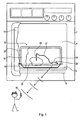
Fig. 1 zeigt einen Backofen 2 mit einem Backraum 4, unter dessen Backraumboden 6 eine Bodenheizung 8 angeordnet ist. Die Bodenheizung 8 kann elektrisch oder eine Gasheizung sein. Der Backraum 4 ist durch eine Tür 10 verschließbar, welche vorzugsweise aus Glas besteht, so dass auch bei geschlossener Tür der Backraum 4 beobachtet werden kann und die Backraumtür keine Abschirmung für elektromagnetische Wellen eines nachfolgend beschriebenen Funksenders bildet.Fig. 1 shows a baking oven 2 with a
Auf dem Backraumboden 6 steht ein Dampfgarer 12, welcher eine Wanne 14 zur Aufnahme 14 eines Flüssigkeitsvorrates (z. B. Wasser) und einen darauf angeordneten gitterförmigen Gargutträger 16 zur Aufnahme von Gargut 18 und einen Deckel 20 aufweist. Der Deckel 20 besteht vorzugsweise aus durchsichtigem, hitzebeständigem Glas. Mithilfe der Bodenheizung 8 des Backofens 2 wird die Flüssigkeit in der Wanne 14 erhitzt und dadurch Dampf erzeugt, welcher das Gargut 18 umströmt, um es zu garen.A
Ein autarkes Messgerät 24 ist eine manuell tragbare mobile Einheit, beispielsweise in Größe und Gewicht eines mobilen Telefons (mobile phone, Handy) oder kleiner und leichter, so dass es bei Bedarf in den Dampfgarer 10 gelegt werden kann, um darin Betriebsdaten zu erfassen.A self-contained
Die Messgeräte-Einheit 24 von Fig. 1 hat ein geschlossenes Gehäuse 26 und einen (oder mehrere) in das Gehäuse 26 integrierten Sensor 28 und/oder einen (oder mehrere) über eine flexible Leitung 27 mit dem Gehäuse 26 verbundenen Sensor 30, der z. B. in das Gargut einsteckbar ist, um in dem Gargutinneren die Temperatur zu messen. Der (oder die) Sensor(en) 28 bzw. 30 ist in dem Gehäuse 26 mit einer darin untergebrachten Sensorschaltung 34 elektrische leitend verbunden.The
Der Sensor 28 und/oder der Sensor 30 kann ein Temperatursensor sein zur Messung seiner Umgebungstemperatur oder ein Feuchte-Sensor sein zum Messen des Feuchtigkeitsgehaltes oder Dampfgehaltes im Dampfgarer oder im Gargut.The
Das Gehäuse 26 enthält ferner einen wiederaufladbaren Akkumulator 36 und einen Funksender 38 zum leitungslosen Senden von elektromagnetischen Funksignalen in Abhängigkeit von den Messsignalen des mindestens einen Sensors 28 und/oder 30 zu einem Funkemfänger 40 eines Überwachungsgerätes 42, welches außerhalb des Dampfgarers 12 und auch außerhalb des Backofens 2 entfernt von diesen angeordnet ist.The
Der Funksender 38 hat eine Sendereichweite von mindestens 10 m, vorzugsweise mindestens 20 m, vorzugsweise zwischen 20 m und 100 m, im abschirmfreien Luftraum. Die Leistung des Funksenders 38 liegt vorzugsweise unter 1,0 W, und noch bevorzugter unter 0,25 W.The
Eine Sendeantenne 44 des Funksenders 38 kann aus dem Gehäuse 26 herausragen oder vorzugsweise in diesem untergebracht oder integriert sein. Die Funkantenne 44 ist vorzugsweise eine geradlinige elektrische Leitung. Geradlinige Antennen ermöglichen die Übertragung von größeren Sendeleistungen als Antennenwicklungen oder Antennenspiralen.A transmitting
Das Messgerät 24 mit den Sensoren 28 und 30 ist wasserdicht bis mindestens 1 bar Wasserdruck und temperaturbeständig bis mindestens 120 °C, vorzugsweise bis mindestens 150 °C oder 200 °C ausgebildet.The measuring
Der Funksender 38 des Messgerätes 24 ist vorzugsweise zum getakteten Senden der Messsignale ausgebildet. Dadurch wird elektrische Energie gespart und es wird die Benutzungsdauer verlängert, bis der Akkumulator 36 wieder elektrisch aufgeladen werden muss. Diese Vorteile sind umso größer, je länger die Sendepausen zwischen den Sendezeiten sind. Beispielsweise wird taktweise nach je 2 Sekunden bis 60 Sekunden ein Messsignalpaket während einer Dauer von 0,5 Sekunden bis 3 Sekunden übertragen.The
Das autarke Überwachungsgerät 42 ist eine manuell tragbare, mobile Einheit, vorzugsweise ein Taschengerät, welches ähnlich wie ein Mobiltelefon (mobile phone, Handy) handlich, klein und leicht ist. Ein solches ist in den Fig. 1 und 3 schematisch dargestellt.The
Der Funkempfänger 40 des Überwachungsgerätes 42 ist zum Empfang der elektromagnetischen Funksignale vom Funksender 38 des Messgerätes 24 auf dessen Sendefrequenz abgestimmt. Das Überwachungsgerät 42 hat ein Gehäuse 46, in welchem der Funkempfänger 40 untergebracht ist und welches ein Display 48 zur Anzeige des Messergebnisses von dem Sensor 28 bzw. 30 aufweist. Die gemessene Temperatur ist als Beispiel mit 100 °C in Fig. 3 angegeben. Ferner kann ein akustischer Signalgeber 50 im Gehäuse 46 vorgesehen sein zur akustischen Anzeige von Warnsignalen entsprechend den empfangenen Funksignalen.The
Ferner enthält das Überwachungsgerät 42 in seinem Gehäuse 46 eine Batterie oder vorzugsweise einen wiederaufladbaren Akkumulator 52 für die autarke Stromversorgung des Überwachungsgerätes.Furthermore, the
Ferner enthält das autarke Überwachungsgerät 42 vorzugsweise eine Alarmuhr 54, an welcher verschiedene Zeitdauern einstellbar sind, deren Restlaufzeit jeweils in einem Zeitdisplay 56 anzeigbar ist. Als Beispiel ist eine Restlaufzeit von 25 Sekunden in Fig. 3 angegeben. Wenn das Zeitdisplay 56 keine Restlaufzeit mehr anzeigt, stellt dies ein Warnsignal für eine Person dar. Als Warnsignal kann zusätzlich oder statt dessen auch ein akustisches Warnsignal erzeugt werden, beispielsweise von dem Signalgeber 50, oder ein Vibrations-Signal, indem das Überwachungsgerät 42 einen Vibrator enthält, welcher bei Zeitablauf das Überwachungsgerät vibrieren lässt.Furthermore, the
Das autarke Überwachungsgerät 42 hat vorzugsweise ein manuelles Bedienelement 58 zum Einstellen der Alarmuhr 54, ein manuelles Bedienelement 59 zum Rückstellen der eingestellten Zeitdauer auf Null, und ein manuelles Bedienelement 60 zum Abschalten des akustischen Alarmes des akustischen Signalgebers 50.The
Das Messgerät 24 und vorzugsweise auch das Überwachungsgerät 42 enthalten vorzugsweise in ihrem Gehäuse 26 bzw. 46 je eine Wiederaufladeschaltung 64 zum elektrischen Aufladen ihres wiederaufladbaren Akkumulators 36 bzw. 52 von einem Ladegerät 62 ohne die Verbindung von elektrischen Kontakten und ohne Herausnehmen des Akkumulators aus dem Gehäuse. Ein mögliches Prinzip ist in Fig. 4 schematisch dargestellt, welches abgebrochen ein Ladegerät 62 und ein abgebrochenes Ende des Messgerätes 24 zeigt. Das Wiederaufladesystem beruht auf dem Transformatorprinzip. Das Ladegerät 62 enthält eine Transformator-Primärwicklung 65, welche über ein Kabel 66 mit einem Stecker 68 an eine Steckdose anschließbar ist, welche eine ortsübliche Netzspannung hat.The measuring
Die Wiederaufladeschaltung 64 enthält eine Gleichrichterschaltung 70 zwischen dem wiederaufladbaren Akkumulator 36 des Messgerätes 24 (bzw. dem wiederaufladbaren Akkumulator 52 des Überwachungsgerätes 42) und einer Transformator-Sekundärwicklung 72, welche von der Primärwicklung 65 des Ladegerätes 62 elektromagnetisch erregt wird, wenn das Messgerät 24 (bzw. das Überwachungsgerät 46) an das Ladegerät 62 angenähert wird. Vorzugsweise hat ein Gerät eine Aufnahme-Steckfassung 74 und das andere Gerät einen Steck-Sockel 76, welche ineinander passen und eine korrekte Position der Primärwicklung 65 zur Sekundärwicklung 72 definieren.The
Der Akkumulator 36 versorgt im Messgerät 24 den Funksender 38 und die elektrische Sensorschaltung 34 mit elektrischer Energie. In ähnlicher Weise versorgt der Akkumulator 52 des Überwachungsgerätes 42 den Funkempfänger 40, das Messsignal-Display 48, den Signalgeber 50 und die elektrische Alarmuhr 54 mit elektrischer Energie.The
Vorzugsweise sind das Messgerät 24 und das Überwachungsgerät 46 in gleicher Weise zum Wiederaufladen durch das Ladegerät 62 ausgebildet, so dass beide alternativ von dem gleichen Ladegerät 62 elektrisch aufgeladen werden können.Preferably,
Claims (12)
- Autonomous measuring apparatus (24) for steam cookers, characterised in that it is a portable unit which can be placed in a steam cooker and which contains a sensor circuit (34) for generating measurement signals in dependence on at least one sensor (28, 30) for detecting operational states in the steam cooker and further contains a radio transmitter (38) for wireless transmission of radio signals in dependence on the measurement signals of the sensor circuit (34) to a radio receiver arranged outside the steam cooker and that the radio transmitter has a transmission range of more than 5 metres, particularly at least 10 metres, in unscreened air space and includes an independent current supply.
- Autonomous measuring apparatus according to claim 1, characterised in that the current supply comprises a current source in the form of a rechargeable accumulator (36) or a battery or at least one receiving chamber therefor.
- Autonomous measuring apparatus according to claim 1 or 2, characterised in that the sensor (30) is arranged externally of the unit and connected therewith.
- Autonomous measuring apparatus according to claim 1 or 2, characterised in that the sensor (28) is integrated the unit.
- Autonomous measuring apparatus according to one of the preceding claims, characterised in that the current source is a rechargeable accumulator (36) and the unit does not have exposed electrical contacts, but is constructed for contactless recharging of the accumulator (36) by a contactless charging apparatus (62).
- Autonomous measuring apparatus according to one of the preceding claims, characterised in that the at least one sensor (28, 30) is constructed for measuring at least one of the following operation states in a steam cooker: sensor environmental temperature in the steam cooker, cooking stock temperature, moisture content and steam content.
- Autonomous measuring apparatus according to one of the preceding claims, characterised in that the radio transmitter (38) is constructed for cyclic transmission of the radio signals.
- Monitoring apparatus, characterised in that it comprises a portable, mobile unit, which contains a radio receiver (40) for reception of electromagnetic radio signals of the radio transmitter (38) of the autonomous measuring apparatus according to one of the preceding claims, that the mobile unit contains optical indicating means (48) and/or an acoustic signal transmitter (50) for indicating data and/or informatory signals in correspondence with the received radio signals, and that the mobile unit has a current source preferably in the form of a battery or a rechargeable accumulator (52) for independent current supply or a receiving chamber therefor.
- Monitoring apparatus according to claim 8, characterised in that it includes a clock (54) at which different time durations are settable and which has a display (56) indicating the respective residual time duration.
- Monitoring apparatus according to claim 8 or 9, characterised in that the current source is a rechargeable accumulator (52) and the unit does not have exposed electrical contacts for connection of the accumulator with an external current source, but is constructed for contactless recharging of the accumulator (52).
- Remote monitoring system for steam cookers, characterised by an autonomous measuring apparatus (24) according to one of claims 1 to 7 and a monitoring apparatus (42) according to claim 8, 9 or 10.
- Remote monitoring system according to claim 11, characterised by an electrical charging station (62) which is constructed for contactless charging of the rechargeable accumulator (36) of the measuring apparatus (24) according to one of claims 1 to 7 and for contactless charging of the rechargeable accumulator (52) of the monitoring apparatus (42) according to claim 7, 8 or 9, and that the measuring apparatus (24) and the monitoring apparatus (42) are constructed for contactless charging of their accumulator and are adapted to the charging apparatus so that the rechargeable accumulators of both apparatus are alternatively electrically contactlessly chargeable.
Applications Claiming Priority (2)
| Application Number | Priority Date | Filing Date | Title |
|---|---|---|---|
| DE102004013621 | 2004-03-19 | ||
| DE102004013621A DE102004013621A1 (en) | 2004-03-19 | 2004-03-19 | Remote monitoring system for steamer and parts thereof |
Publications (2)
| Publication Number | Publication Date |
|---|---|
| EP1577653A1 EP1577653A1 (en) | 2005-09-21 |
| EP1577653B1 true EP1577653B1 (en) | 2007-01-03 |
Family
ID=34833205
Family Applications (1)
| Application Number | Title | Priority Date | Filing Date |
|---|---|---|---|
| EP05102157A Not-in-force EP1577653B1 (en) | 2004-03-19 | 2005-03-18 | Remote supervision system for steam cooker and parts thereof |
Country Status (3)
| Country | Link |
|---|---|
| EP (1) | EP1577653B1 (en) |
| AT (1) | ATE350654T1 (en) |
| DE (2) | DE102004013621A1 (en) |
Families Citing this family (19)
| Publication number | Priority date | Publication date | Assignee | Title |
|---|---|---|---|---|
| DE602005023174D1 (en) * | 2005-10-27 | 2010-10-07 | Electrolux Home Prod Corp | Network of programmatic home appliances |
| DE202006009284U1 (en) * | 2006-06-13 | 2007-10-25 | Rational Ag | Cooking appliance with cooking state condition monitoring |
| DE102007058941A1 (en) * | 2007-12-07 | 2009-06-10 | BSH Bosch und Siemens Hausgeräte GmbH | Accessory part for use in baking tube of steam food-baking oven, has circular water evaporator covering water bowl made of translucent material such as glass, where evaporator comprises body made of porous material such as stone |
| DE102009042305A1 (en) * | 2009-09-19 | 2011-03-24 | Frank Domnick | Cooking device for cooking meat, has thermometer for measuring internal temperature of food slices, and display for displaying measured internal temperature of food slices, where thermometer is wirelessly connected with display |
| DE102010028493A1 (en) * | 2010-05-03 | 2011-11-03 | BSH Bosch und Siemens Hausgeräte GmbH | Control unit for a household workstation, household workstation and system from the household workstation and the control panel |
| DE102010039515A1 (en) | 2010-08-19 | 2012-02-23 | BSH Bosch und Siemens Hausgeräte GmbH | Dampfgargerätvorrichtung |
| DE102014217010A1 (en) | 2014-08-27 | 2016-03-03 | BSH Hausgeräte GmbH | Controlling a temperature of a food |
| ES2774351T3 (en) * | 2015-02-13 | 2020-07-20 | Vorwerk Co Interholding | Procedure for measuring a temperature inside a kitchen appliance |
| EP3722761B1 (en) | 2015-06-25 | 2023-06-07 | Apption Labs Ltd. | Method of using a food thermometer |
| US11946812B2 (en) | 2015-06-25 | 2024-04-02 | Apption Labs Limited | Food thermometer and method of using thereof |
| US11506545B2 (en) | 2015-06-25 | 2022-11-22 | Apption Labs Limited | Food thermometer and method of using thereof |
| US10429251B2 (en) * | 2015-09-30 | 2019-10-01 | Anova Applied Electronics, Inc. | Wireless temperature sensor for sous vide cooking |
| EP3308683B1 (en) * | 2016-10-11 | 2020-07-01 | Electrolux Appliances Aktiebolag | Cooking vessel for an oven cavity of a cooking oven |
| US11723489B2 (en) | 2017-06-01 | 2023-08-15 | Apption Labs Limited | Temperature sensing devices and wireless communication improvements for cooking appliances |
| US11056763B2 (en) | 2017-06-01 | 2021-07-06 | Apption Labs Limited | Wireless communication improvements for cooking appliances |
| DE102017211020A1 (en) * | 2017-06-29 | 2019-01-03 | Robert Bosch Gmbh | Measuring device and a system comprising a measuring device and a charging unit |
| WO2019212617A2 (en) * | 2018-05-03 | 2019-11-07 | Matrix Product Development, Inc. | Wireless temperature-measurement system |
| CN110393428B (en) * | 2019-08-07 | 2020-12-15 | 山东大学 | Instant noodle cooking equipment and use method |
| EP4198473A1 (en) * | 2021-12-16 | 2023-06-21 | Vorwerk & Co. Interholding GmbH | Rechargeable electric food thermometer and charging device |
Family Cites Families (9)
| Publication number | Priority date | Publication date | Assignee | Title |
|---|---|---|---|---|
| DE2161371C3 (en) * | 1971-12-10 | 1978-11-16 | Fischer, Karl, 7519 Oberderdingen | Control device |
| US4297557A (en) * | 1976-05-03 | 1981-10-27 | Robertshaw Controls Company | Microwave oven temperature indicator and control means |
| US4088863A (en) * | 1977-05-20 | 1978-05-09 | Rockwell International Corporation | Cordless meat probe for microwave oven |
| US4340796A (en) * | 1978-08-31 | 1982-07-20 | Sharp Kabushiki Kaisha | Wireless temperature-sensing system inclusive of thermally-responsive oscillator |
| JPS5688294A (en) * | 1979-12-21 | 1981-07-17 | Tokyo Shibaura Electric Co | Electronic range |
| DE4421373A1 (en) * | 1994-06-18 | 1995-12-21 | Wiesheu Wiwa Gmbh | Oven for the heat treatment of lumpy foods |
| DE19615357A1 (en) * | 1995-05-11 | 1996-11-21 | Miele & Cie | Household appliance has spatially separate display |
| DE19849075A1 (en) * | 1998-10-24 | 2000-04-27 | Ego Elektro Geraetebau Gmbh | Operating control for electric cooking hob or oven uses hand-held remote-control device for transmission of control and regulation signals |
| US7128466B2 (en) * | 2001-07-09 | 2006-10-31 | Ewig Industries Co., Ltd. | Dual thermometer system |
-
2004
- 2004-03-19 DE DE102004013621A patent/DE102004013621A1/en not_active Withdrawn
-
2005
- 2005-03-18 DE DE502005000272T patent/DE502005000272D1/en active Active
- 2005-03-18 AT AT05102157T patent/ATE350654T1/en not_active IP Right Cessation
- 2005-03-18 EP EP05102157A patent/EP1577653B1/en not_active Not-in-force
Also Published As
| Publication number | Publication date |
|---|---|
| DE102004013621A1 (en) | 2005-10-06 |
| ATE350654T1 (en) | 2007-01-15 |
| DE502005000272D1 (en) | 2007-02-15 |
| EP1577653A1 (en) | 2005-09-21 |
Similar Documents
| Publication | Publication Date | Title |
|---|---|---|
| EP1577653B1 (en) | Remote supervision system for steam cooker and parts thereof | |
| EP3056882B1 (en) | Method for measuring a temperature within a kitchen appliance | |
| EP2369353B1 (en) | Contact-free current measuring device and consumer energy meter | |
| DE102011086904A1 (en) | Device and method for inductive energy transmission | |
| DE102012217975A1 (en) | Household appliance e.g. washing machine, has transmitter transferring radio signal to control device in wireless manner, and generator with contact surfaces providing electrical power between surfaces based on difference in temperature | |
| EP1934568A1 (en) | Documentation system for the catering trade | |
| US11219333B2 (en) | Wireless temperature sensing system for a cooking appliance | |
| US10883883B2 (en) | Wireless probe for food, and system and method for wireless food temperature real-time monitoring | |
| DE3836099A1 (en) | Telemetering device (remote measuring device) for measuring and transmitting various data within a cooking pot (saucepan) | |
| KR20150069952A (en) | Wireless power transmission apparatus enable to be installed at wall | |
| DE102010039072A1 (en) | Apparatus for operating household appliance i.e. smart pot, has communication interface receiving information from external communication medium, where apparatus displays received information in operation unit | |
| EP2802844A1 (en) | Sensor system for a cooking device | |
| DE102009029250B4 (en) | System with base stations and at least one household attachment and method for operating the system | |
| CN210157418U (en) | Plug-in heater with universal bayonet | |
| CN110146183A (en) | Wireless probe and wireless temperature real-time monitoring system for food | |
| EP2991444B1 (en) | Regulating a temperature of an item to be cooked | |
| CN208547421U (en) | Ring network cabinet temp measuring system | |
| EP0909113A3 (en) | In-the-ear hearing aid | |
| CN100589138C (en) | Hot fault warning system device | |
| DE102004059006A1 (en) | Charging accumulator in hearing aid involves charge controller arranged in hearing aid which is charged in receiving bowl along with transmitter device having switching mechanism, which has no contact with accumulator | |
| DE102018108223B4 (en) | Thermometer and temperature monitoring system | |
| US20130073231A1 (en) | In-situ data acquisition systems and methods | |
| DE102020109484A1 (en) | Inductive kitchen system | |
| EP3855146A1 (en) | Supply unit for generating electrical energy, kitchen utensil and kitchen system | |
| DE102019107595A1 (en) | GRILL WITH BATTERY SUPPLY SYSTEM AND MEASURING EQUIPMENT |
Legal Events
| Date | Code | Title | Description |
|---|---|---|---|
| PUAI | Public reference made under article 153(3) epc to a published international application that has entered the european phase |
Free format text: ORIGINAL CODE: 0009012 |
|
| AK | Designated contracting states |
Kind code of ref document: A1 Designated state(s): AT BE BG CH CY CZ DE DK EE ES FI FR GB GR HU IE IS IT LI LT LU MC NL PL PT RO SE SI SK TR |
|
| AX | Request for extension of the european patent |
Extension state: AL BA HR LV MK YU |
|
| 17P | Request for examination filed |
Effective date: 20060321 |
|
| AKX | Designation fees paid |
Designated state(s): AT BE BG CH CY CZ DE DK EE ES FI FR GB GR HU IE IS IT LI LT LU MC NL PL PT RO SE SI SK TR |
|
| GRAP | Despatch of communication of intention to grant a patent |
Free format text: ORIGINAL CODE: EPIDOSNIGR1 |
|
| GRAS | Grant fee paid |
Free format text: ORIGINAL CODE: EPIDOSNIGR3 |
|
| GRAA | (expected) grant |
Free format text: ORIGINAL CODE: 0009210 |
|
| AK | Designated contracting states |
Kind code of ref document: B1 Designated state(s): AT BE BG CH CY CZ DE DK EE ES FI FR GB GR HU IE IS IT LI LT LU MC NL PL PT RO SE SI SK TR |
|
| PG25 | Lapsed in a contracting state [announced via postgrant information from national office to epo] |
Ref country code: SI Free format text: LAPSE BECAUSE OF FAILURE TO SUBMIT A TRANSLATION OF THE DESCRIPTION OR TO PAY THE FEE WITHIN THE PRESCRIBED TIME-LIMIT Effective date: 20070103 Ref country code: FI Free format text: LAPSE BECAUSE OF FAILURE TO SUBMIT A TRANSLATION OF THE DESCRIPTION OR TO PAY THE FEE WITHIN THE PRESCRIBED TIME-LIMIT Effective date: 20070103 Ref country code: DK Free format text: LAPSE BECAUSE OF FAILURE TO SUBMIT A TRANSLATION OF THE DESCRIPTION OR TO PAY THE FEE WITHIN THE PRESCRIBED TIME-LIMIT Effective date: 20070103 Ref country code: IE Free format text: LAPSE BECAUSE OF FAILURE TO SUBMIT A TRANSLATION OF THE DESCRIPTION OR TO PAY THE FEE WITHIN THE PRESCRIBED TIME-LIMIT Effective date: 20070103 Ref country code: NL Free format text: LAPSE BECAUSE OF FAILURE TO SUBMIT A TRANSLATION OF THE DESCRIPTION OR TO PAY THE FEE WITHIN THE PRESCRIBED TIME-LIMIT Effective date: 20070103 Ref country code: PL Free format text: LAPSE BECAUSE OF FAILURE TO SUBMIT A TRANSLATION OF THE DESCRIPTION OR TO PAY THE FEE WITHIN THE PRESCRIBED TIME-LIMIT Effective date: 20070103 |
|
| REG | Reference to a national code |
Ref country code: GB Ref legal event code: FG4D Free format text: NOT ENGLISH |
|
| REF | Corresponds to: |
Ref document number: 502005000272 Country of ref document: DE Date of ref document: 20070215 Kind code of ref document: P |
|
| REG | Reference to a national code |
Ref country code: IE Ref legal event code: FG4D Free format text: LANGUAGE OF EP DOCUMENT: GERMAN |
|
| PG25 | Lapsed in a contracting state [announced via postgrant information from national office to epo] |
Ref country code: BG Free format text: LAPSE BECAUSE OF FAILURE TO SUBMIT A TRANSLATION OF THE DESCRIPTION OR TO PAY THE FEE WITHIN THE PRESCRIBED TIME-LIMIT Effective date: 20070403 Ref country code: SE Free format text: LAPSE BECAUSE OF FAILURE TO SUBMIT A TRANSLATION OF THE DESCRIPTION OR TO PAY THE FEE WITHIN THE PRESCRIBED TIME-LIMIT Effective date: 20070403 |
|
| PG25 | Lapsed in a contracting state [announced via postgrant information from national office to epo] |
Ref country code: ES Free format text: LAPSE BECAUSE OF FAILURE TO SUBMIT A TRANSLATION OF THE DESCRIPTION OR TO PAY THE FEE WITHIN THE PRESCRIBED TIME-LIMIT Effective date: 20070414 |
|
| PG25 | Lapsed in a contracting state [announced via postgrant information from national office to epo] |
Ref country code: IS Free format text: LAPSE BECAUSE OF FAILURE TO SUBMIT A TRANSLATION OF THE DESCRIPTION OR TO PAY THE FEE WITHIN THE PRESCRIBED TIME-LIMIT Effective date: 20070503 |
|
| PG25 | Lapsed in a contracting state [announced via postgrant information from national office to epo] |
Ref country code: PT Free format text: LAPSE BECAUSE OF FAILURE TO SUBMIT A TRANSLATION OF THE DESCRIPTION OR TO PAY THE FEE WITHIN THE PRESCRIBED TIME-LIMIT Effective date: 20070604 |
|
| NLV1 | Nl: lapsed or annulled due to failure to fulfill the requirements of art. 29p and 29m of the patents act | ||
| GBV | Gb: ep patent (uk) treated as always having been void in accordance with gb section 77(7)/1977 [no translation filed] |
Effective date: 20070103 |
|
| EN | Fr: translation not filed | ||
| REG | Reference to a national code |
Ref country code: IE Ref legal event code: FD4D |
|
| PLBE | No opposition filed within time limit |
Free format text: ORIGINAL CODE: 0009261 |
|
| STAA | Information on the status of an ep patent application or granted ep patent |
Free format text: STATUS: NO OPPOSITION FILED WITHIN TIME LIMIT |
|
| PG25 | Lapsed in a contracting state [announced via postgrant information from national office to epo] |
Ref country code: GB Free format text: LAPSE BECAUSE OF FAILURE TO SUBMIT A TRANSLATION OF THE DESCRIPTION OR TO PAY THE FEE WITHIN THE PRESCRIBED TIME-LIMIT Effective date: 20070103 Ref country code: SK Free format text: LAPSE BECAUSE OF FAILURE TO SUBMIT A TRANSLATION OF THE DESCRIPTION OR TO PAY THE FEE WITHIN THE PRESCRIBED TIME-LIMIT Effective date: 20070103 |
|
| 26N | No opposition filed |
Effective date: 20071005 |
|
| BERE | Be: lapsed |
Owner name: BSH BOSCH UND SIEMENS HAUSGERATE G.M.B.H. Effective date: 20070331 |
|
| PG25 | Lapsed in a contracting state [announced via postgrant information from national office to epo] |
Ref country code: BE Free format text: LAPSE BECAUSE OF NON-PAYMENT OF DUE FEES Effective date: 20070331 Ref country code: CZ Free format text: LAPSE BECAUSE OF FAILURE TO SUBMIT A TRANSLATION OF THE DESCRIPTION OR TO PAY THE FEE WITHIN THE PRESCRIBED TIME-LIMIT Effective date: 20070103 Ref country code: RO Free format text: LAPSE BECAUSE OF FAILURE TO SUBMIT A TRANSLATION OF THE DESCRIPTION OR TO PAY THE FEE WITHIN THE PRESCRIBED TIME-LIMIT Effective date: 20070103 |
|
| PG25 | Lapsed in a contracting state [announced via postgrant information from national office to epo] |
Ref country code: MC Free format text: LAPSE BECAUSE OF NON-PAYMENT OF DUE FEES Effective date: 20070331 |
|
| PG25 | Lapsed in a contracting state [announced via postgrant information from national office to epo] |
Ref country code: LT Free format text: LAPSE BECAUSE OF FAILURE TO SUBMIT A TRANSLATION OF THE DESCRIPTION OR TO PAY THE FEE WITHIN THE PRESCRIBED TIME-LIMIT Effective date: 20070103 |
|
| PG25 | Lapsed in a contracting state [announced via postgrant information from national office to epo] |
Ref country code: IT Free format text: LAPSE BECAUSE OF FAILURE TO SUBMIT A TRANSLATION OF THE DESCRIPTION OR TO PAY THE FEE WITHIN THE PRESCRIBED TIME-LIMIT Effective date: 20070103 Ref country code: GR Free format text: LAPSE BECAUSE OF FAILURE TO SUBMIT A TRANSLATION OF THE DESCRIPTION OR TO PAY THE FEE WITHIN THE PRESCRIBED TIME-LIMIT Effective date: 20070404 Ref country code: FR Free format text: LAPSE BECAUSE OF FAILURE TO SUBMIT A TRANSLATION OF THE DESCRIPTION OR TO PAY THE FEE WITHIN THE PRESCRIBED TIME-LIMIT Effective date: 20070824 |
|
| PG25 | Lapsed in a contracting state [announced via postgrant information from national office to epo] |
Ref country code: AT Free format text: LAPSE BECAUSE OF NON-PAYMENT OF DUE FEES Effective date: 20070318 |
|
| PG25 | Lapsed in a contracting state [announced via postgrant information from national office to epo] |
Ref country code: FR Free format text: LAPSE BECAUSE OF FAILURE TO SUBMIT A TRANSLATION OF THE DESCRIPTION OR TO PAY THE FEE WITHIN THE PRESCRIBED TIME-LIMIT Effective date: 20070103 |
|
| PG25 | Lapsed in a contracting state [announced via postgrant information from national office to epo] |
Ref country code: EE Free format text: LAPSE BECAUSE OF FAILURE TO SUBMIT A TRANSLATION OF THE DESCRIPTION OR TO PAY THE FEE WITHIN THE PRESCRIBED TIME-LIMIT Effective date: 20070103 |
|
| PG25 | Lapsed in a contracting state [announced via postgrant information from national office to epo] |
Ref country code: CY Free format text: LAPSE BECAUSE OF FAILURE TO SUBMIT A TRANSLATION OF THE DESCRIPTION OR TO PAY THE FEE WITHIN THE PRESCRIBED TIME-LIMIT Effective date: 20070103 |
|
| PG25 | Lapsed in a contracting state [announced via postgrant information from national office to epo] |
Ref country code: LU Free format text: LAPSE BECAUSE OF NON-PAYMENT OF DUE FEES Effective date: 20070318 |
|
| PG25 | Lapsed in a contracting state [announced via postgrant information from national office to epo] |
Ref country code: TR Free format text: LAPSE BECAUSE OF FAILURE TO SUBMIT A TRANSLATION OF THE DESCRIPTION OR TO PAY THE FEE WITHIN THE PRESCRIBED TIME-LIMIT Effective date: 20070103 Ref country code: HU Free format text: LAPSE BECAUSE OF FAILURE TO SUBMIT A TRANSLATION OF THE DESCRIPTION OR TO PAY THE FEE WITHIN THE PRESCRIBED TIME-LIMIT Effective date: 20070704 |
|
| REG | Reference to a national code |
Ref country code: CH Ref legal event code: PL |
|
| PG25 | Lapsed in a contracting state [announced via postgrant information from national office to epo] |
Ref country code: CH Free format text: LAPSE BECAUSE OF NON-PAYMENT OF DUE FEES Effective date: 20090331 Ref country code: LI Free format text: LAPSE BECAUSE OF NON-PAYMENT OF DUE FEES Effective date: 20090331 |
|
| REG | Reference to a national code |
Ref country code: DE Ref legal event code: R081 Ref document number: 502005000272 Country of ref document: DE Owner name: BSH HAUSGERAETE GMBH, DE Free format text: FORMER OWNER: BSH BOSCH UND SIEMENS HAUSGERAETE GMBH, 81739 MUENCHEN, DE Effective date: 20150407 |
|
| REG | Reference to a national code |
Ref country code: DE Ref legal event code: R084 Ref document number: 502005000272 Country of ref document: DE |
|
| PGFP | Annual fee paid to national office [announced via postgrant information from national office to epo] |
Ref country code: DE Payment date: 20220331 Year of fee payment: 18 |
|
| REG | Reference to a national code |
Ref country code: DE Ref legal event code: R119 Ref document number: 502005000272 Country of ref document: DE |
|
| PG25 | Lapsed in a contracting state [announced via postgrant information from national office to epo] |
Ref country code: DE Free format text: LAPSE BECAUSE OF NON-PAYMENT OF DUE FEES Effective date: 20231003 |