EP1577616A1 - Outdoor unit of refrigerator, and electrical equipment box of outdoor unit - Google Patents
Outdoor unit of refrigerator, and electrical equipment box of outdoor unit Download PDFInfo
- Publication number
- EP1577616A1 EP1577616A1 EP03758958A EP03758958A EP1577616A1 EP 1577616 A1 EP1577616 A1 EP 1577616A1 EP 03758958 A EP03758958 A EP 03758958A EP 03758958 A EP03758958 A EP 03758958A EP 1577616 A1 EP1577616 A1 EP 1577616A1
- Authority
- EP
- European Patent Office
- Prior art keywords
- casing
- outdoor unit
- electrical equipment
- box
- equipment box
- Prior art date
- Legal status (The legal status is an assumption and is not a legal conclusion. Google has not performed a legal analysis and makes no representation as to the accuracy of the status listed.)
- Withdrawn
Links
Images






Classifications
-
- F—MECHANICAL ENGINEERING; LIGHTING; HEATING; WEAPONS; BLASTING
- F24—HEATING; RANGES; VENTILATING
- F24F—AIR-CONDITIONING; AIR-HUMIDIFICATION; VENTILATION; USE OF AIR CURRENTS FOR SCREENING
- F24F5/00—Air-conditioning systems or apparatus not covered by F24F1/00 or F24F3/00, e.g. using solar heat or combined with household units such as an oven or water heater
-
- F—MECHANICAL ENGINEERING; LIGHTING; HEATING; WEAPONS; BLASTING
- F24—HEATING; RANGES; VENTILATING
- F24F—AIR-CONDITIONING; AIR-HUMIDIFICATION; VENTILATION; USE OF AIR CURRENTS FOR SCREENING
- F24F1/00—Room units for air-conditioning, e.g. separate or self-contained units or units receiving primary air from a central station
- F24F1/06—Separate outdoor units, e.g. outdoor unit to be linked to a separate room comprising a compressor and a heat exchanger
- F24F1/46—Component arrangements in separate outdoor units
- F24F1/48—Component arrangements in separate outdoor units characterised by air airflow, e.g. inlet or outlet airflow
- F24F1/50—Component arrangements in separate outdoor units characterised by air airflow, e.g. inlet or outlet airflow with outlet air in upward direction
-
- F—MECHANICAL ENGINEERING; LIGHTING; HEATING; WEAPONS; BLASTING
- F24—HEATING; RANGES; VENTILATING
- F24F—AIR-CONDITIONING; AIR-HUMIDIFICATION; VENTILATION; USE OF AIR CURRENTS FOR SCREENING
- F24F1/00—Room units for air-conditioning, e.g. separate or self-contained units or units receiving primary air from a central station
- F24F1/06—Separate outdoor units, e.g. outdoor unit to be linked to a separate room comprising a compressor and a heat exchanger
- F24F1/20—Electric components for separate outdoor units
-
- F—MECHANICAL ENGINEERING; LIGHTING; HEATING; WEAPONS; BLASTING
- F24—HEATING; RANGES; VENTILATING
- F24F—AIR-CONDITIONING; AIR-HUMIDIFICATION; VENTILATION; USE OF AIR CURRENTS FOR SCREENING
- F24F1/00—Room units for air-conditioning, e.g. separate or self-contained units or units receiving primary air from a central station
- F24F1/06—Separate outdoor units, e.g. outdoor unit to be linked to a separate room comprising a compressor and a heat exchanger
- F24F1/20—Electric components for separate outdoor units
- F24F1/22—Arrangement or mounting thereof
-
- F—MECHANICAL ENGINEERING; LIGHTING; HEATING; WEAPONS; BLASTING
- F24—HEATING; RANGES; VENTILATING
- F24F—AIR-CONDITIONING; AIR-HUMIDIFICATION; VENTILATION; USE OF AIR CURRENTS FOR SCREENING
- F24F1/00—Room units for air-conditioning, e.g. separate or self-contained units or units receiving primary air from a central station
- F24F1/06—Separate outdoor units, e.g. outdoor unit to be linked to a separate room comprising a compressor and a heat exchanger
- F24F1/20—Electric components for separate outdoor units
- F24F1/24—Cooling of electric components
-
- F—MECHANICAL ENGINEERING; LIGHTING; HEATING; WEAPONS; BLASTING
- F24—HEATING; RANGES; VENTILATING
- F24F—AIR-CONDITIONING; AIR-HUMIDIFICATION; VENTILATION; USE OF AIR CURRENTS FOR SCREENING
- F24F1/00—Room units for air-conditioning, e.g. separate or self-contained units or units receiving primary air from a central station
- F24F1/06—Separate outdoor units, e.g. outdoor unit to be linked to a separate room comprising a compressor and a heat exchanger
- F24F1/46—Component arrangements in separate outdoor units
-
- F—MECHANICAL ENGINEERING; LIGHTING; HEATING; WEAPONS; BLASTING
- F24—HEATING; RANGES; VENTILATING
- F24F—AIR-CONDITIONING; AIR-HUMIDIFICATION; VENTILATION; USE OF AIR CURRENTS FOR SCREENING
- F24F13/00—Details common to, or for air-conditioning, air-humidification, ventilation or use of air currents for screening
- F24F13/20—Casings or covers
- F24F2013/207—Casings or covers with control knobs; Mounting controlling members or control units therein
Definitions
- the present invention relates to an outdoor unit of a refrigerator and an electrical equipment box of an outdoor unit. More particularly, the present invention relates to a type of refrigerator outdoor unit that draws in air from a side face, exchanges heat with the air, and blows the air out through a top face and an electrical equipment box that is provided inside the casing of such an outdoor unit and serves to house electrical components.
- Some of the outdoor units of air conditioning systems which are one type of refrigerator, are of the type that draw in air from a side face, exchange heat with the air, and blow the air out through a top face.
- This kind of outdoor unit is used to condition the air of office buildings and the like; it is installed on the roof of a building and connected to a plurality of indoor units through communication pipings.
- This kind of outdoor unit is provided with a generally rectangular-parallelepiped-shaped casing inside of which are provided such devices as a compressor, a heat exchanger, and a blower fan.
- An air inlet is provided on a side face of the casing and an upwardly directed air outlet is provided on a top face of the casing.
- air inlets are provided in the two side faces and the rear face of the casing but not the front face.
- the heat exchanger serves to exchange heat with the air drawn in from the air inlets and is arranged inside the casing so as to face each of the air inlets.
- the blower fan is a propeller fan for discharging air through the air outlet after the air has exchanged heat at the heat exchanger and is provided in an upper portion of the casing in such a manner as to be aligned with the air outlet.
- an electrical equipment box that houses an inverter, a control circuit board, and other electrical components is provided inside the casing in such a manner as to face the front face so that it can be accessed from the front face side.
- the electrical equipment box is a generally rectangular-parallelepiped-shaped box provided below the blower fan when viewed from the front face side of the casing.
- the electrical equipment box When viewed from the top face side of the casing, the electrical equipment box has an elongated shape that runs toward both side faces and the amount by which it protrudes toward the rear face is small.
- the casing When viewed from the front face side of the casing, the casing is divided into two spaces, i.e. a left space and right space (see, for example, Japanese Laid-Open Patent Publication No. 6-281204).
- the blower fan With an outdoor unit provided with such an electrical equipment box, the blower fan is driven and air is drawn in through the air inlets. Then, after the air exchanges heat with a refrigerant in the heat exchanger, the air is discharged from the air outlet.
- the air that is drawn in through the air inlets and discharged from the air outlet due to the blower fan being driven flows from bottom to top inside the casing (see, for example, Japanese Laid-Open Patent Publication No. 8-128678).
- the outdoor unit just described requires a large capacity in order to accommodate as many indoor units as possible.
- This increase in size causes such problems as a decrease in the loading efficiency of the unit during transport and difficulty in carrying the unit to such places as the roof of a building. Consequently, it is necessary to make the outdoor unit more compact in addition to increasing the capacity of the outdoor unit. It is particularly necessary to reduce the size of the outdoor unit when viewed from the top face because the size of the outdoor unit when viewed from the top face has a large effect on the loading of the unit during transport and the carrying of the unit to such places as the roof of a building.
- the electrical equipment box must have a prescribed volume in order to house all of the various electrical equipment components. It is also necessary to cool the electrical equipment box on a continuous basis when the outdoor unit is in operation because several electrical components that emit large amounts of heat are housed inside the electrical equipment box. Consequently, the electrical equipment box must be arranged so as to protrude into the portion where the blower fan is conducting its blowing work by the amount necessary to accomplish the cooling.
- the electrical components housed in the electrical equipment box of the outdoor unit described above are arranged in such a manner as to be separated according to function and characteristics.
- electrical components that emit large amounts of heat (high heat emission components) - including strong current components such as inverters and reactors - are arranged in one of the two aforementioned left and right spaces and electrical components that emit small amounts of heat (low heat emission components) - including weak current components such as control circuit boards - are arranged in the other of the two planarly divided spaces.
- it is necessary to make the outdoor unit described above more compact particularly from the perspective of transport, it is necessary to reduce the size of the outdoor unit when viewed from the top face.
- the electrical equipment box which has two spaces, one on the left and one on the right). Consequently, it is necessary to make the electrical equipment box more compact.
- the amount by which the electrical equipment box protrudes from the front face toward the rear face is determined by the size of the largest electrical component in the case of an electrical equipment box having two spaces (one on the left and one on the right). Consequently, it is likely that some of the space inside the electrical equipment box will be wasted. Moreover, if one attempts to reduce the size of the outdoor unit when viewed from the top face, the amount by which the electrical equipment box protrudes toward the rear face will be larger, the flow of air from bottom to top inside the casing will be impeded, and the air flow resistance will increase. Consequently, there is the possibility that the blowing performance of the blower fan will decline and that noise will increase.
- an electrical equipment box that is constructed to have two spaces, one on the left and one on the right, in which the electrical components are arranged in a planar manner arranged generally along a holizontal plane.
- the electrical equipment box it is feasible to divide the electrical equipment box into a plurality of electrical equipment boxes arranged in places that do not impede the blowing work of the blower fan, such a configuration would increase the number of assembly steps required for the electrical equipment box and make it less convenient to access the electrical equipment box after the outdoor unit has been installed. It would also be difficult to arrange the electrical components such that they are separated according to function and characteristics.
- a first object of the present invention is to reduce the size of a refrigerator outdoor unit of the type that draws in air from a side face, exchanges heat with the air, and blows the air out through a top face while ensuring that the electrical equipment box has sufficient volume and suppressing the increase in air flow resistance that results from reducing the size of the outdoor unit.
- a second object of the present invention is to suppress the increase in the air flow resistance inside a refrigerator outdoor unit of the type that draws in air from a side face, exchanges heat with the air, and blows the air out through a top face without damaging the effectiveness with which the electrical equipment box is cooled.
- a third object of the present invention is to eliminate wasted space inside and reduce the size of the electrical equipment box of a refrigerator outdoor unit of the type that draws in air from a side face, exchanges heat with the air, and blows the air out through a top face.
- the outdoor unit of refrigerator described in claim 1 is a refrigerator outdoor unit of the type that draws in air from a side face, exchanges heat with the air, and blows the air out through a top face, the outdoor unit being provided with a casing, an axial fan, and an electrical equipment box.
- the axial fan is provided in an upper portion of the casing and is configured to blow air that has been drawn in from a side face of the casing out through a top face of the casing.
- the electrical equipment box is arranged inside the casing and has a first box part that is provided below the axial fan and a second box part that is provided below the first box part and has a larger surface area in a plan view than the first box part.
- the air flow path in a position close to the axial fan is widened so that the air flow is not impeded and the increase in air flow resistance inside the outdoor unit can be suppressed.
- the outdoor unit of refrigerator described in claim 2 is an outdoor unit in accordance with claim 1, wherein the casing is generally rectangular in a plan view.
- the electrical equipment box is arranged such that it faces one side face of the casing.
- the second box part is provided such that it bulges outward beyond the first box part in a direction opposite of, i.e., away from, said one side face of the casing.
- the electrical equipment box can be accessed easily from one side face of the casing because the electrical equipment box is arranged so as to face one side face of the casing and the second box part bulges outward in a direction opposite of, i.e., away from, said side face of the casing.
- the outdoor unit can be assembled more easily and worked on more easily onsite.
- the outdoor unit of refrigerator described in claim 3 is an outdoor unit in accordance with claim 1 or 2, wherein the electrical equipment box is further provided with a slanted part.
- the slanted part is provided vertically-between the second box part and the first box part and is configured such that its surface area in a plan view decreases as one moves from the top end of the second box part to the bottom end of the first box part.
- the air drawn in through a side face of the casing can be made to flow smoothly toward the top face of the casing because a slanted part is provided between the second box part and the first box part of the electrical equipment box. As a result, the increase in air flow resistance inside the outdoor unit can be suppressed.
- the outdoor unit of refrigerator described in claim 4 is a refrigerator outdoor unit of the type that draws in air from a side face, exchanges heat with the air, and blows the air out through a top face, the outdoor unit being provided with a casing, an axial fan, and an electrical equipment box.
- the axial fan is provided in an upper portion of the casing and is configured to blow air drawn in from a side face of the casing out through a top face of the casing.
- the electrical equipment box is arranged inside the casing such that it faces one side face of the casing, and a portion of the electrical equipment box facing in a direction opposite of, i.e., away from said one side face of the casing is shaped such that it follows the streamline along which the air drawn in from a side face of the casing flows toward the top face of the casing.
- this outdoor unit when the axial fan provided in an upper portion of the casing is driven, air is drawn in from a side face of the casing and, after exchanging heat, blown out through a top face of the casing.
- the air drawn in through a side face of the casing can be made to flow smoothly toward the top face of the casing because the electrical equipment box is arranged inside the casing such that it faces one side face of the casing and a portion of the electrical equipment box facing in a direction opposite of, i.e., away from said one side face of the casing is shaped such that it follows the streamline along which the air drawn in from a side face of the casing flows toward the top face of the casing.
- the increase in air flow resistance inside the outdoor unit can be suppressed because the electrical equipment box does not impede the flow of air from a side face of the casing toward the top face.
- the outdoor unit of refrigerator described in claim 5 is an outdoor unit in accordance with any one of claims 2 to 4, wherein the electrical equipment box is arranged such that, in a plan view, it is offset from the center of said one side face of the casing.
- the electrical equipment box is arranged such that it is offset from the center of said one side face of the casing, it is easy to secure an air flow path in a position close to the axial fan where the effect on the air flow resistance is large and the increase in air flow resistance is suppressed even further.
- the outdoor unit of refrigerator described in claim 6 is an outdoor unit in accordance with any one of claims 1 to 5, wherein the electrical equipment box is arranged such that, in a plan view, it overlaps the region where the axial fan conducts blowing work.
- the electrical equipment box is arranged such that, in a plan view of the casing, it overlaps the region where the axial fan conducts blowing work. Even though the electrical equipment box overlaps the region where the axial fan conducts blowing work, the surface area of the overlapping portion in the vicinity of the axial fan can be held to a minimum because the electrical equipment box is provided with a first box part and a second box part. In particular, the increase of the air flow resistance inside the outdoor unit can be suppressed more efficiently because the amount of overlap near the outer circumference of the axial fan, where the effect on the air flow resistance is large, can be reduced.
- the outdoor unit of refrigerator described in claim 7 is a refrigerator outdoor unit of the type that draws in air from a side face, exchanges heat with the air, and blows the air out through a top face, the outdoor unit being provided with a casing, an axial fan, and an electrical equipment box.
- the casing is generally rectangular in a plan view.
- the axial fan is provided in an upper portion of the casing and is configured to blow air drawn in from a side face of the casing out through a top face of the casing.
- the electrical equipment box is arranged below the axial fan inside the casing such that, in a plan view of the casing, it overlaps the region where the axial fan conducts blowing work.
- the ratio of the overlapping surface area (i.e., the surface area of the portion where the electrical equipment box overlaps the region where the axial fan conducts blowing work) to the blowing surface area (i.e., the surface area of the region where the axial fan conducts blowing work) is 0.09 or less.
- this outdoor unit when the axial fan provided in an upper portion of the casing is driven, air is drawn in from a side face of the casing and, after exchanging heat, blown out through a top face of the casing.
- the electrical equipment box is arranged such that it overlaps the region where the axial fan conducts blowing work and configured such that the surface area ratio of the overlapping surface area is 0.09 or less.
- this surface area ratio was discovered to be a value with which the increase in the air flow resistance can be suppressed without damaging the effectiveness with which the electrical equipment box is cooled.
- This surface area ratio enables the amount by which the electrical equipment box protrudes into the region where the axial fan conducts blowing work to be suppressed and the increase in air flow resistance to be suppressed without damaging the effectiveness with which the electrical equipment box is cooled.
- the outdoor unit of refrigerator described in claim 8 is an outdoor unit in accordance with claim 7, wherein, in a plan view of the casing, the ratio of the fan outside diameter of the axial fan to the length of a short side of the casing is 0.89 or greater.
- the fan outside diameter of the axial fan is larger in comparison with the length of a short side of the casing in order to reduce the size of the casing in a plan view.
- the outdoor unit of refrigerator described in claim 9 is an outdoor unit in accordance with claim 8, wherein, in a plan view of the casing, the ratio of the length of a short side of the casing to the length of a long side of the casing is 0.80 or greater.
- the shape of the casing in a plan view is brought closer to a square shape in order to reduce the size of the casing in a plan view.
- the outdoor unit of refrigerator described in claim 10 is an outdoor unit in accordance with any one of claims 7 to 9, wherein the electrical equipment box is arranged such that it faces one side face of the casing.
- the outdoor unit can be assembled more easily and worked on more easily onsite because the electrical equipment box can be accessed easily from one side face of the casing.
- the outdoor unit of refrigerator described in claim 11 is an outdoor unit in accordance with claim 10, wherein the electrical equipment box is arranged such that, in a plan view of the casing, it is offset from the center of said one side face of the casing.
- the surface area of the overlapping portion can be reduced and the increase in air flow resistance can be suppressed because the electrical equipment box is offset from the center of said one side face.
- the outdoor unit of refrigerator described in claim 12 is an outdoor unit in accordance with claim 11, wherein the electrical equipment box is arranged such that, in a plan view of the casing, it is located in a corner section of the casing.
- the surface area of the overlapping portion can be reduced and the increase in air flow resistance can be suppressed because the electrical equipment box is arranged in a corner section of the casing.
- the outdoor unit of refrigerator described in claim 13 is an outdoor unit in accordance with any one of claims 7 to 12, wherein the electrical equipment box is shaped such that its surface area in a plan view increases as one moves downward away from the axial fan.
- the electrical equipment box is shaped such that, in a plan view, its surface area increases as one moves downward away from the axial fan, an air flow path can be secured in a position close to the axial fan where the effect on the air flow resistance is large and the air drawn in through a side face of the casing can be made to flow smoothly toward the top face of the casing. As a result, the increase in the air flow resistance can be suppressed.
- the electrical equipment box of outdoor unit described in claim 14 is configured to house electrical equipment components and is provided inside the casing of a refrigerator outdoor unit of the type that draws in air from a side face, exchanges heat with the air, and blows the air out through a top face, the electrical equipment box being provided with a box main body, a lid member, and a partition plate.
- the box main body is provided such that it faces one side face of the casing and has an opening in the side thereof that faces said one side face.
- the lid member is arranged so as to cover the opening in the box main body.
- the partition plate is provided inside the box main body and serves to partition the space inside the box main body into a front space on the lid member side and a back space on the side opposite from the lid member.
- the electrical equipment box of outdoor unit described in claim 15 is an electrical equipment box in accordance with claim 14, wherein the partition plate is made of resin.
- the front space and the back space can be electrically insulated from each other with ease. It is also possible to mount electrical components directly to the partition plate.
- the electrical equipment box of outdoor unit described in claim 16 is an electrical equipment box in accordance with claim 14 or 15, wherein the electrical components include first electrical components that are accessed with a high degree of frequency after the outdoor unit is installed and second electrical components that are accessed with a low degree of frequency after the outdoor unit is installed.
- the first electrical components are arranged in the front space.
- the first electrical components i.e., electrical components (e.g., a control circuit board) that are accessed with a high degree of frequency after the outdoor unit is installed, are arranged in the front space and can therefore be accessed by simply removing the lid member (e.g., when accessing a control circuit board for the purpose of adjusting settings).
- the electrical equipment box of outdoor unit described in claim 17 is an electrical equipment box in accordance with any one of claims 14 to 16, wherein the electrical components include low heat emission components that emit small amounts of heat when the outdoor unit is in operation and high heat emission components that emit large amounts of heat when the outdoor unit is in operation.
- the high heat emission components are arranged in the back space.
- the electrical equipment box of outdoor unit described in claim 18 is an electrical equipment box in accordance with claims 17, wherein the box main body has cooling fins that project in a direction opposite of said one side face of the casing.
- the cooling fins projecting in a direction opposite of said one side face of the casing enable cooling of the back space by the air flowing through the inside of the casing to be promoted.
- the electrical equipment box of outdoor unit described in claim 19 is an electrical equipment box in accordance with any one of claims 14 to 18, wherein the partition plate has a window section that links the front space and back space together.
- a window section is provided in the partition plate and electrical components arranged in the back space can be accessed without removing the partition plate.
- the component can be accessed while leaving the partition plate in its installed state.
- first electrical components i.e., electrical components that are accessed with a high degree of frequency after the outdoor unit is installed
- the electrical equipment box of outdoor unit described in claim 20 is an electrical equipment box in accordance with any one of claims 14 to 19, wherein a bulged part that bulges outward in a direction opposite of, i.e., away from, said one side face of the casing is provided on a portion of the box main body.
- the bulged part makes it possible to widen a portion of the front space and the back space and, thus, makes it possible to install long electrical components, such as noise filters.
- the electrical equipment box of outdoor unit described in claim 21 is an electrical equipment box in accordance with claim 20, wherein the bulged part is provided on a lower portion of the box main body.
- the increase in air flow resistance inside the outdoor unit can be suppressed because the bulged part is provided on a lower portion of the box main body.
- the electrical equipment box of outdoor unit described in claim 22 is an electrical equipment box in accordance with claim 20, wherein the box main body comprises a sheet metal box part made of metal and a resin box part made of resin.
- cooling can be promoted by arranging high heat emission components (i.e., inverters, reactors, and other components that emit a large amount of heat) in the sheet metal box part.
- high heat emission components i.e., inverters, reactors, and other components that emit a large amount of heat
- the electrical equipment box of outdoor unit described in claim 23 is an electrical equipment box in accordance with claim 22, wherein the bulged part is provided on a lower portion of the box main body.
- the sheet metal box part constitutes the upper portion of the box main body.
- the resin box part constitutes the lower portion of the box main body and includes the bulged part.
- the bulged part is easy to form because it is formed by molding resin. Also, making a portion of the box main body out of resin can contribute to reducing the cost of the electrical equipment box.
- FIG. 1 shows an outdoor unit 1 for an air conditioning system (which is one type of refrigerator) in accordance with a first embodiment of the present invention.
- the outdoor unit 1 forms part of a multiple-unit type air conditioning system. It is installed on the roof of an office building or the like and connected to a plurality of indoor units through communication pipings.
- the outdoor unit 1 is of the type that draws in air from a side face, exchanges heat with the air, and blows the air out through a top face and is provided with the following: a casing 12; an outdoor refrigerant circuit 13 housed inside the casing 12; a blower fan 14 (axial fan) provided in an upper portion of the casing 12; and an electrical equipment box 15 housed inside the casing 12.
- the casing 12 has the general shape of a rectangular parallelepiped and comprises chiefly the following: supports 21 arranged at each of the four corners of the casing 12; a top panel 22; a front panel 23; a rear panel 24; a pair of side panels 25; and a bottom panel 26.
- the supports 21 are pillar-like members that are arranged at each corner of the casing 12 and extend from the top edge to the bottom edge of the casing 12.
- the supports 21 secure and support the top panel 22, the front panel 23, the rear panel 24, the pair of side panels 25, and the bottom panel 26.
- An air outlet 22a (top face) comprising an opening is provided in the center of the top panel 22 and a fan grill 22b is provided in such a manner as to cover the top of the opening. Air drawn into the casing 12 is discharged upward through the air outlet 22a.
- the front panel 23 comprises an upper front panel 23a arranged below the top panel 22, a middle front panel 23b arranged below the upper front panel 23a, and a lower front panel 23c arranged below the middle front panel 23b.
- the front panel 23 is constructed so as to be divided into three sections: upper, middle, and lower.
- the rear panel 24 has an air inlet 24a for drawing air into the casing 12.
- the air inlet 24a (not shown in the figures) comprises an opening that occupies substantially the entire face of the rear panel 24.
- the two side panels 25 have an air inlets 25a for drawing air into the casing 12.
- each of the air inlets 25a comprises an opening that occupies a portion of the side panel 25 that excludes a portion close to the front panel 23. Air is drawn into the casing 12 through these air inlets 24a, 25a.
- the bottom panel 26 supports and secures the devices and piping that make up the outdoor refrigerant circuit 13.
- the bottom panel 26 is supported on the four supports 21 such that a space is formed between the bottom panel 26 and the installation surface.
- the outdoor refrigerant circuit 13 includes a compressor 13a, a heat exchanger 13b, and piping that serves to connect these devices together.
- the compressor 13a, heat exchanger 13b, and other main devices are secured to the bottom panel 26.
- the devices and piping that make up the outdoor refrigerant circuit 13 are arranged chiefly in the bottom section of the casing 12.
- the heat exchanger 13b is U-shaped and arranged such that it faces the three air inlets 24a, 25a.
- the heat exchanger 13b is capable of exchanging heat between a refrigerant and air drawn in through the air inlets 24a, 25a.
- the blower fan 14 is a propeller fan and is arranged in an upper portion of the casing 12 in such a manner as to be aligned with the air outlet 22a.
- the blower fan 14 includes a plurality of propeller blades 14a, a hub 14b that secures the radially inward portions of the propeller blades 14a, and a fan motor 14c that rotationally drives the hub 14b.
- the fan motor 14c is fixed to the casing 12 by means of a support frame (not shown). More specifically, the blower fan 14 is arranged in a position corresponding to the vertical position of the upper front panel 23a.
- blower fan 14 draws outdoor air into the casing from side faces of the casing 12 through the air inlets 24a, 25a and, after the air has passed through the heat exchanger 13b, directs the air to the top of the casing 12 where the air is discharged through the air outlet 22a.
- the electrical equipment box 15 is a box body in which such electrical equipment components as an inverter and a control circuit board are housed and is arranged such that it faces the front panel 23. More specifically, the electrical equipment box 15 is arranged such that it faces the middle front panel 23b and avoids the bottom portion of the casing 12 where the many devices and piping that make up the outdoor refrigerant circuit 13 are arranged. That is, the electrical equipment box 15 is arranged in a position below the blower fan 14 and above the lower front panel 23c.
- Figure 2 is a view from direction A in Figure 1 showing the outdoor unit 1 with the fan grill 22b of the top panel 22 excluded from the figure.
- Figure 3 is a view of the outdoor unit 1 from direction B in Figure 1 showing an internal cross section of the casing 12 with the compressor 13a and other devices excluded from the figure.
- the electrical equipment box 15 has a first box part 15a that is provided below the blower fan 14 and a second box part 15b that is provided below the first box part 15a and has a larger surface area Sb in a plan view than the surface area Sa of first box part 15a in a plan view.
- the first box part 15a is the portion having the width dimension Wa and the length dimension La in a plan view.
- the second box part 15b is the portion having the width dimension Wb and the length dimension Lb in a plan view.
- the width Wb is the same as the width Wa.
- the length Lb is longer than the length La and the second box part 15b bulges toward the rear panel 24 in comparison to the first box part 15a.
- the electrical equipment box 15 is arranged such that, in a plan view, it overlaps the portion where the blower fan 14 conducts blowing work.
- the "region where the blower fan 14 conducts blowing work” refers to the region where the propeller blades 14a pass when the blower fan 14 is running.
- said portion is the annular region T obtained by subtracting the circular region defined by the radius r of the hub 14b from the circular region defined by the radius R from the rotational center O of the blower fan 14 to the radially outer edge of the propeller blades 14a (hereinafter referred to as the fan outside diameter D, which is two times the radius R).
- the portion of the electrical equipment box 15 close to the blower fan 14 (more specifically, the portion of the surface area Sa of the first box part 15a) that overlaps the region T in a plan view has a surface area Sc (cross-hatched area in Figure 2). It is preferred that the ratio (Sc/Sd) of the overlapping surface area Sc to the surface area Sd of the region T be 0.09 or less.
- the electrical equipment box 15 is arranged such that it is offset from the center of the front panel 23 (more specifically, from the center line O-P in Figure 2). In this embodiment, the electrical equipment box 15 is offset to the right of the center line O-P of the front panel 23 and arranged close to the corner of the casing 12.
- the electrical equipment box 15 has a slanted part 15c that is provided vertically-between the second box part 15b and the first box part 15a in a side view and is configured such that its surface area in a plan view decreases as one moves from the top end of the second box part 15b to the bottom end of the first box part 15a. Consequently, the portion of the electrical equipment box 15 facing the rear panel 24 is shaped such that it follows the streamline F along which the air drawn in from the air inlets 24a, 25a on side faces of the casing 12 flows toward the air outlet 22a of the casing 12.
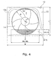
- this electrical equipment box 15 protrudes somewhat more toward the rear panel 24 than a conventional electrical equipment box (e.g., that shown in Figure 4) that is long in the widthwise direction and reaches across almost the entire width of the front panel 23, and the volume required to house the various electrical components is secured by providing the second box part 15b below the first box part 15a.
- a conventional electrical equipment box e.g., that shown in Figure 4
- the ratio (D/L) of the fan outside diameter D of the blower fan 14 to the length L of a short side of the casing 12 in a plan view is 0.89 or larger, the outside edge of the air outlet 22a approaches close to the front panel 23 and rear panel 24. Also, in a plan view, the ratio (L/W) of the length L of a short side of the casing 12 to the length W of a long side is 0.80 or larger.
- the size of the casing 12 of the outdoor unit 1 has been made more compact in a plan view.
- the blower fan 14 When the outdoor unit 1 is in operation, the blower fan 14 is driven and, as a result, air is drawn into the inside of the casing 12 through side faces thereof, i.e., through the air inlets 24a, 25a.
- the air drawn into the casing 12 passes through and exchanges heat with the heat exchanger 13b, which is arranged such that it faces the air inlets 24a, 25a.
- the air flows upward and is blown out through the air outlet 22a by the propeller blades 14a of the blower fan 14.
- the air flows along such a streamline as to be directed simultaneously inward toward the inner portion of the casing and upward toward the air outlet 22a.
- an air flow similar to streamline F develops at the portion of the electrical equipment box 15 that faces the rear panel 24.
- the electrical equipment box 15 is configured to have a first box part 15a provided close to the blower fan 14, an air flow path is secured in a position close to the blower fan 14 where the effect on the air flow resistance is large and the increase in air flow resistance is suppressed. Additionally, since a slanted part 15c is provided vertically-between the second box part 15b and the first box part 15a, a surface is formed which follows a streamline F along which the air drawn in from the air inlets 24a, 25a on side faces of the casing 12 flows toward the air outlet 22a of the casing 12. As a result, the air that flows along the streamline F can be made to flow smoothly upward.
- the electrical equipment box 15 is configured to have a first box part 15a provided close to the blower fan 14 and an overlapping surface area ratio (Sc/Sd) of 0.09 or less, an air flow path is secured in a position close to the blower fan 14 where the effect on the air flow resistance is large and an overlapping surface area Sc is secured that is sufficient to enable cooling of the electrical equipment box 15.
- the electrical equipment box 15 is cooled and the increase in air flow resistance is suppressed.
- the length L of the short side of the casing 12, i.e., 770 millimeters, is a size that can fit through the passages leading to the roofs of buildings and through the doors of elevators.
- the ratio (D/L) of the fan outside diameter D to the length L of a short side of the casing 12 is 0.91 and the ratio (L/W) of the short side length L to the length W of a long side of the casing 12 is 0.83.
- the size conditions for the electrical equipment box 15 in Experiment 1 were as follows: the length La of the first box part 15a was 160 millimeters; the length Lb of the second box part 15b was 230 millimeters; and the widths Wa, Wb of the first box part 15a and the second box part 15b were both 410 millimeters.
- the electrical equipment box 15 was arranged close to a corner of the casing 12 such that the overlapping area ratio (Sc/Sd) was 0.09.
- the size conditions for the electrical equipment box 915 in Experiment 2 were as follows: the lengths La, Lb of the first box part 15a and the second box part 15b were both 150 millimeters and the widths Wa, Wb of the first box part 15a and the second box part 15b were both 800 millimeters.
- the electrical equipment box 915 was arranged to face the middle of the front panel 23 of the casing 12 such that the overlapping area ratio (Sc/Sd) was 0.10.
- Figure 5 is a view of the outdoor unit 1 from direction B in Figure 1 showing an internal cross section of the casing 12 with the compressor 13a and other devices excluded from the figure (the cooling fins of the electrical equipment box are shown).
- Figure 6 is a perspective view of the external appearance of the electrical equipment box 15 and
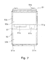
- Figure 7 is a view from direction E in Figure 6.
- the electrical equipment box comprises chiefly a box main body 51, a lid member 52, and a partition plate 53.
- the box main body 51 is provided such that it faces the front panel 23 of the casing 12 and has an opening in the side thereof that faces the front panel 23.
- the lid member 52 is a plate-like member arranged so as to cover the opening in the box main body 51.
- the partition plate 53 is provided inside the box main body 51 such that it partitions the space inside the box main body 51 into a front space C on the side closer to the front panel 23 of the casing 12 (i.e., lid member 52 side) and a back space D on the side closer to the rear panel 24 of the casing 12 (i.e., the side opposite from the lid member 52 side).
- the electrical equipment box 15 has a two-layered structure divided into two spaces, i.e., a front space C and a back space D, in which electrical components can be housed.
- the box main body 51 has a pair of side face parts 51a, a rear face part 51b, a top face part 51c, and a bottom face part 51d.
- the box main body 51 is made of sheet metal.
- the side face parts 51a are generally L-shaped such that the lower portions thereof bulge outward toward the rear panel 24 of the casing 12.
- Each of the side face parts 51a comprises an upper side face part 51e that has a depth length La and a lower side face part 51f that is provided below the upper side face part 51e and has a depth length Lb that is larger than the depth length La.
- Lid fastening parts 51g for fastening the lid member 52 are provided on the vertical edges of the side face parts 51a that are closest to the front panel 23 of the casing 12.
- Each of the upper side face parts 51e is provided with a rectangular hole 51h comprising a rectangular hole.
- the rear face part 51b is the portion of the box main body 51 constituting the face that faces toward the rear panel 24 of the casing 12.
- the rear face part 51b comprises an upper rear face part 51i that corresponds the upper side face parts 51e of the side face parts 51a and a lower rear face part 51j that corresponds to the lower side face parts 51f of the side face parts 51a.
- Cooling fins 54, 55 that protrude toward the rear panel 24 of the casing 12 are provided on the upper rear face part 51i.
- the top face part 51c is the portion of the box main body 51 constituting the face that faces toward the top panel 22, and it is configured such that it slants downward toward the inner portion of the casing 12.
- the top face part 51c is provided with an upper fastening part 51k configured to be fastened by a support frame (not shown) of the casing 12.
- the bottom face part 51d is the portion of the box main body 51 constituting the face that faces toward the bottom panel 26, and it is configured such that a portion is cut away on the lid member 52 side thereof.
- the bottom face part 51d is also provided with a lower fastening part 51m configured to be fastened by a support frame (not shown) of the casing 12.
- the lower side face parts 51f of the pair of side face parts 51a, the lower rear face parts 51j of the rear face part 51b, and the bottom face part 51d constitute a bulging part 56 that bulges toward the rear panel 24 of the casing 12 and increases the depth dimensions of the spaces C and D.
- the lid member 52 is a generally rectangular plate-like member that is fastened to the lid fastening parts 51g with screws or the like.
- the lid member 52 is made of sheet metal.
- the partition plate 53 in this embodiment comprises two plate-like members, an upper partition plate 53a and a lower partition plate 53b.
- the partition plates 53a, 53b are made of resin.
- the upper partition plate 53a is a plate-like member provided inside the box main body 51 in a position corresponding to the upper side face parts 51e of the side face parts 51a.
- Each of the two side faces of the upper partition plate 53a is provided with a mating part 53c comprising a rectangular projection.
- the mating parts 53c mate with the rectangular hole parts 51h provided in the upper side face parts 51e and thereby support the upper partition plate 53a.
- the lower partition plate 53b is a plate-like member provided inside the box main body 51 in a position corresponding to the lower side face parts 51 f of the side face parts 51a.
- a support part 53d that is supported on the bottom face part 51d of the box main body 51 is provided on a bottom portion of the lower partition plate 53b.
- a window section 57 that links the front space C and back space D together is provided vertically-between upper partition plate 53a and the lower partition plate 53b.
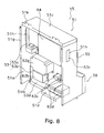
- Figure 8 is a perspective view showing the electrical equipment box 15 with the lid member 52 removed
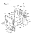
- Figure 9 is an exploded perspective view showing the electrical equipment box 15 with the partition plate 53 removed.
- the main electrical components housed inside the electrical equipment box 15 include such strong current components as a reactor 61c and inverters 61a, 61b for the compressor 13a and the blower fan 14 and such weak current components as noise filters 62a, 62b for the inverters 61a, 61b, terminal blocks 63a to 63d, and a control circuit board 64.
- the inverters 61a, 61b and reactors 61c are high heat emission components that emit large amounts of heat when the outdoor unit is running and the control circuit board 64 is a low heat emission component that emits a small amount of heat when the outdoor unit is running.
- the inverters 61a, 61b and reactor 61c (which are strong current components) are arranged in the back space D in order to promote their cooling when the outdoor unit is in operation. More specifically, the inverter 61a is arranged in a position aligned with the cooling fins 54, the inverter 61b is arranged in a position aligned with the cooling fins 55, and the reactor 61c is arranged above the inverter 61b. Meanwhile, the control circuit board 64 (which is a weak current component) is arranged in the front space C and is fastened directly to the partition plate 53 (in this embodiment, the upper partition plate 53a). Thus, the strong current components and weak current components are arranged in separate spaces C and D inside the electric equipment box 15.
- the terminal blocks 63a to 63d and the control circuit board 64 are arranged in the front space C in consideration of their characteristic of being accessed with a high degree of frequency after the outdoor unit 1 is installed. More specifically, the terminal blocks 63a to 63d are mounted to the lower partition plate 53b and the control circuit board 64 is mounted to the upper partition plate 53a. The terminal blocks 63a to 63d and the control circuit board 64 are mounted directly to the partition plates 53a, 53b because the partition plates 53a, 53b are made of resin and can be electrically insulated from the box main body 51.
- the inverters 61 a, 61 b, the reactor 61c, and the noise filters 62a, 62b (second electrical components), which are accessed with a low degree of frequency after the outdoor unit 1 is installed, are arranged in the back space D.
- the minimum required access to the inverters 61a, 61b arranged in the back space D can be accomplished without removing the partition plate 53 because the terminal connections are visible from the lid member 52 side through the window section 57 (see Figure 7) provided vertically-between the partition plates 53a, 53b.
- the noise filters 62a, 62b which are comparatively long electrical components, are arranged in the lower portion of the back space D, i.e., in the back space D portion of the bulged part 56.
- the control circuit board 64, inverters 61a, 61b, and other board-shaped electrical components are arranged in the upper space (which has a narrower depth dimension) of the box main body 51 and the noise filters 62a, 62b, terminal blocks 63a to 63d, and other comparatively long electrical components are arranged in the lower space (more specifically the bulged part 56, which has a wider depth dimension) of the box main body 51.
- the electrical equipment box 15 uses space more efficiently.
- the air drawn into the casing 12 passes through the heat exchanger 13b and then flows along such a streamline as to be directed simultaneously inward toward the inner portion of the casing and upward toward the air outlet 22a.
- an air flow similar to streamline F develops at the portion of the electrical equipment box 15 that faces the rear panel 24 (see Figure 5).
- the inverters 61a, 61b and reactor 61c are arranged inside the electrical control box 15 and emit heat constantly when the compressor 13a and blower fan 14 are running. However, the inverters 61a, 61b and reactor 61c are sufficiently cooled because they are arranged in the back space D and mounted to the rear face part 51b of the box main body 51 and because cooling fins 54, 55 are provided on the rear face part 51b. Consequently, it is difficult for the heat to reach the front space C side and the control circuit board 64, which has a low heat resistance, is protected.
- the bulged part 56 (which corresponds to second box part 15b) of the electrical equipment box 15 is provided on lower portion of the electrical equipment box 15, an air flow path is secured in a position close to the blower fan 14 (which is located in an upper portion of the electrical equipment box 15 corresponding to the first box part 15a) where the effect on the air flow resistance is large and the increase in air flow resistance is suppressed.
- An outdoor unit 1 and electrical equipment box 15 in accordance with this embodiment have the following features.
- box main body 51 of the electrical equipment box 15 described heretofore is made of sheet metal, it is also acceptable to create an electric equipment box 115 in which the portions corresponding to the upper side face parts 51e of the side face parts 51a are made out of sheet metal and the portions corresponding to the lower side face parts 51f are made out of resin.
- an electrical equipment box 115 in accordance with this variation has, as shown in Figure 10, a box main body 151 comprising a sheet metal box part 158 and a resin box part 159, a lid member 52, and a partition plate 53 (more specifically, an upper partition plate 53a and a lower partition plate 53b).
- the sheet metal body part 158 is a sheet metal member that includes the top face part 151c, the upper side face parts 151e of the side face parts 151a, and the upper rear face parts 151i of the rear face part 151b.
- the resin body part 159 is a molded resin member that includes the lower side face parts 151f of the side face parts 151a, and the lower rear face parts 151j of the rear face part 151b, and the bottom face part 151d.
- the sheet metal box part 158 and the resin box part 159 are fastened together by means of a plurality of claw parts 158a that are provided on a bottom edge of the sheet metal box part 158 and engaging hole parts 159a that are provided in a top edge portion of the resin box part 159 and configured such that the claw parts 158a can engage therewith.
- the electrical equipment box 115 similarly to the electrical equipment box 15 described previously, makes it possible to arrange the inverters 61a, 61b, the reactor 62, and other high heat emission components in the sheet metal box part 158 and achieves the same effects as the previously described electrical equipment box 15.
- an electrical equipment box 115 it is easier to form the bulged part 156 because the lower portion of the box main body 151 is made of resin. Therefore, the time and effort spent on sheet metal bending work is reduced in comparison with box main bodies made entirely out of sheet metal and the cost of the electrical equipment box 115 can be reduced.
- the electrical equipment box 15 of the first embodiment has a slanted part 15c that is provided vertically-between the first box part 15a and the second box part 15b and is configured such that its surface area in a plan view decreases as one moves from the top end of the second box part 15b to the bottom end of the first box part 15a.
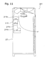
- an electrical equipment box 215 for an outdoor unit 201 according to this embodiment
- a recessed part 215c having a smaller length Lc than the length La of first box part 215a is formed vertically-between the first box part 215a and the second box part 215b.
- This electrical equipment box 21 maintains a shape that generally follows the streamline F of the air and makes it possible to suppress the increase in air flow resistance inside the outdoor unit 201, similarly to the outdoor unit 1.
- the electrical equipment boxes 15, 115, 215 are arranged such that they face the front panel 23 of the casing 12 and, in a plan view of the casing 12, are offset from the center of the front panel 23 of the casing 12.
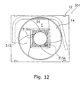
- an outdoor unit 301 in which an electrical equipment box 315 shaped as shown in Figures 12 and 13 is arranged directly below the hub 14b of the blower fan 14.
- the electrical equipment box 315 has a first box part 315a positioned closer to the blower fan 14 and a second box part 315b located there-below.
- a slanted part 315c is provided vertically-between the first box part 315a and the second box part 315b.
- the increase in the air flow resistance inside the outdoor unit 301 can be suppressed similarly to outdoor units 1, 201 of the first and second embodiments by setting the surface area ratio (Sc/Sd) of the surface area Sc of the overlapping portion (cross-hatched portion in Figure 12) to the surface area Sd of the region T to 0.09 or less.
- Employing the present invention makes it possible to reduce the size a refrigerator outdoor unit of the type that draws in air from a lateral face, exchanges heat with the air, and blows the air out of a top face while ensuring that the electrical equipment box has sufficient volume and suppressing the increase in the air flow resistance.
- Employing the present invention also makes it possible to suppress the increase in the air flow resistance in a refrigeraor outdoor unit of the type that draws in air from a lateral face, exchanges heat with the air, and blows the air out of a top face without disturbing the effectiveness with which the electrical equipment box is cooled.
- Employing the present invention also makes it possible to eliminate wasted space inside and reduce the size of the electrical equipment box of a refrigeratior outdoor unit of the type that draws in air from a lateral face, exchanges heat with the air, and blows the air out of a top face.
Landscapes
- Engineering & Computer Science (AREA)
- Chemical & Material Sciences (AREA)
- Combustion & Propulsion (AREA)
- Mechanical Engineering (AREA)
- General Engineering & Computer Science (AREA)
- Life Sciences & Earth Sciences (AREA)
- Sustainable Development (AREA)
- Other Air-Conditioning Systems (AREA)
- Cooling Or The Like Of Electrical Apparatus (AREA)
- Devices That Are Associated With Refrigeration Equipment (AREA)
Abstract
The present invention reduces the size of a refrigerator outdoor unit of the type that
draws in air from a lateral face, exchanges heat with the air, and blows the air out of a top
face while ensuring that the electrical equipment box has sufficient volume and
suppressing the increase in the air flow resistance. The air conditioning system outdoor
unit (1) is of the type that draws in air from air inlets (24a, 25a) provided in the rear
panel (24) and a pair of side panels (25) of a casing (12), exchanges heat with the air, and
blows the air out through an air outlet (22a) provided in a top panel (22). The outdoor
unit (1) is provided with an axial fan (14) and an electrical equipment box (15) arranged
inside the casing (12). The electrical equipment box (15) is arranged inside the casing
(12) and has a first box part (15a) that is provided below the axial fan (14) and a second
box part (15b) that is provided below the first box part (15a) and has a larger surface area
in a plan view than the first box part (15a).
Description
The present invention relates to an outdoor unit of a refrigerator and an electrical
equipment box of an outdoor unit. More particularly, the present invention relates to a
type of refrigerator outdoor unit that draws in air from a side face, exchanges heat with
the air, and blows the air out through a top face and an electrical equipment box that is
provided inside the casing of such an outdoor unit and serves to house electrical
components.
Some of the outdoor units of air conditioning systems, which are one type of
refrigerator, are of the type that draw in air from a side face, exchange heat with the air,
and blow the air out through a top face. This kind of outdoor unit is used to condition the
air of office buildings and the like; it is installed on the roof of a building and connected
to a plurality of indoor units through communication pipings. This kind of outdoor unit is
provided with a generally rectangular-parallelepiped-shaped casing inside of which are
provided such devices as a compressor, a heat exchanger, and a blower fan. An air inlet is
provided on a side face of the casing and an upwardly directed air outlet is provided on a
top face of the casing. More specifically, air inlets are provided in the two side faces and
the rear face of the casing but not the front face. The heat exchanger serves to exchange
heat with the air drawn in from the air inlets and is arranged inside the casing so as to
face each of the air inlets. The blower fan is a propeller fan for discharging air through
the air outlet after the air has exchanged heat at the heat exchanger and is provided in an
upper portion of the casing in such a manner as to be aligned with the air outlet.
Additionally, an electrical equipment box that houses an inverter, a control circuit board,
and other electrical components is provided inside the casing in such a manner as to face
the front face so that it can be accessed from the front face side. More specifically, the
electrical equipment box is a generally rectangular-parallelepiped-shaped box provided
below the blower fan when viewed from the front face side of the casing. When viewed
from the top face side of the casing, the electrical equipment box has an elongated shape
that runs toward both side faces and the amount by which it protrudes toward the rear
face is small. When viewed from the front face side of the casing, the casing is divided
into two spaces, i.e. a left space and right space (see, for example, Japanese Laid-Open
Patent Publication No. 6-281204).
With an outdoor unit provided with such an electrical equipment box, the blower fan
is driven and air is drawn in through the air inlets. Then, after the air exchanges heat
with a refrigerant in the heat exchanger, the air is discharged from the air outlet. The air
that is drawn in through the air inlets and discharged from the air outlet due to the blower
fan being driven flows from bottom to top inside the casing (see, for example, Japanese
Laid-Open Patent Publication No. 8-128678).
The outdoor unit just described requires a large capacity in order to accommodate as
many indoor units as possible. However, simply speaking, in order to increase the
capacity of the outdoor unit, it is necessary to enlarge the heat exchanger and the blower
fan and, as a result, the size of the outdoor unit becomes large. This increase in size
causes such problems as a decrease in the loading efficiency of the unit during transport
and difficulty in carrying the unit to such places as the roof of a building. Consequently,
it is necessary to make the outdoor unit more compact in addition to increasing the
capacity of the outdoor unit. It is particularly necessary to reduce the size of the outdoor
unit when viewed from the top face because the size of the outdoor unit when viewed
from the top face has a large effect on the loading of the unit during transport and the
carrying of the unit to such places as the roof of a building.
However, if the size of the outdoor unit when viewed from the top face is constrained,
the amount by which the electrical equipment box protrudes into the portion where the
blower fan is conducting its blowing work will be larger because the blower fan will be
larger due to the increase in capacity of the outdoor unit. As a result, the flow of air
from bottom to top inside the casing will be impeded and the air flow resistance will
increase. Consequently, there is the possibility that the blowing performance of the
blower fan will decline and that noise will increase.
Meanwhile, the electrical equipment box must have a prescribed volume in order to
house all of the various electrical equipment components. It is also necessary to cool the
electrical equipment box on a continuous basis when the outdoor unit is in operation
because several electrical components that emit large amounts of heat are housed inside
the electrical equipment box. Consequently, the electrical equipment box must be
arranged so as to protrude into the portion where the blower fan is conducting its
blowing work by the amount necessary to accomplish the cooling.
Also, the electrical components housed in the electrical equipment box of the outdoor
unit described above are arranged in such a manner as to be separated according to
function and characteristics. For example, electrical components that emit large
amounts of heat (high heat emission components) - including strong current components
such as inverters and reactors - are arranged in one of the two aforementioned left and
right spaces and electrical components that emit small amounts of heat (low heat
emission components) - including weak current components such as control circuit
boards - are arranged in the other of the two planarly divided spaces. Moreover, it is
necessary to make the outdoor unit described above more compact; particularly from the
perspective of transport, it is necessary to reduce the size of the outdoor unit when
viewed from the top face. However, if the size of the outdoor unit when viewed from the
top face is constrained, it becomes spatially difficult to arrange the electrical equipment
box (which has two spaces, one on the left and one on the right). Consequently, it is
necessary to make the electrical equipment box more compact.
Since the sizes of the electrical components arranged inside the electrical equipment
box are various, the amount by which the electrical equipment box protrudes from the
front face toward the rear face is determined by the size of the largest electrical
component in the case of an electrical equipment box having two spaces (one on the left
and one on the right). Consequently, it is likely that some of the space inside the
electrical equipment box will be wasted. Moreover, if one attempts to reduce the size of
the outdoor unit when viewed from the top face, the amount by which the electrical
equipment box protrudes toward the rear face will be larger, the flow of air from bottom
to top inside the casing will be impeded, and the air flow resistance will increase.
Consequently, there is the possibility that the blowing performance of the blower fan will
decline and that noise will increase.
Thus, it is difficult to reduce the size of an electrical equipment box that is
constructed to have two spaces, one on the left and one on the right, in which the
electrical components are arranged in a planar manner arranged generally along a
holizontal plane. Although it is feasible to divide the electrical equipment box into a
plurality of electrical equipment boxes arranged in places that do not impede the blowing
work of the blower fan, such a configuration would increase the number of assembly
steps required for the electrical equipment box and make it less convenient to access the
electrical equipment box after the outdoor unit has been installed. It would also be
difficult to arrange the electrical components such that they are separated according to
function and characteristics.
A first object of the present invention is to reduce the size of a refrigerator outdoor
unit of the type that draws in air from a side face, exchanges heat with the air, and blows
the air out through a top face while ensuring that the electrical equipment box has
sufficient volume and suppressing the increase in air flow resistance that results from
reducing the size of the outdoor unit.
A second object of the present invention is to suppress the increase in the air flow
resistance inside a refrigerator outdoor unit of the type that draws in air from a side face,
exchanges heat with the air, and blows the air out through a top face without damaging
the effectiveness with which the electrical equipment box is cooled.
A third object of the present invention is to eliminate wasted space inside and reduce
the size of the electrical equipment box of a refrigerator outdoor unit of the type that
draws in air from a side face, exchanges heat with the air, and blows the air out through a
top face.
The outdoor unit of refrigerator described in claim 1 is a refrigerator outdoor unit of
the type that draws in air from a side face, exchanges heat with the air, and blows the air
out through a top face, the outdoor unit being provided with a casing, an axial fan, and an
electrical equipment box. The axial fan is provided in an upper portion of the casing and
is configured to blow air that has been drawn in from a side face of the casing out
through a top face of the casing. The electrical equipment box is arranged inside the
casing and has a first box part that is provided below the axial fan and a second box part
that is provided below the first box part and has a larger surface area in a plan view than
the first box part.
In this outdoor unit, when the axial fan provided in an upper portion of the casing is
driven, air is drawn in from a side face of the casing and, after exchanging heat, blown
out through a top face of the casing. Since the electrical equipment box is configured
such that the first box part is below the axial fan, an air flow path is secured in a position
close to the axial fan where the effect on the air flow resistance is large and the increase
in air flow resistance is suppressed. Meanwhile, since the electrical equipment box is
configured such that the second box part is positioned below the first box part, i.e., far
from the axial fan, the volume required for housing the various electrical components is
secured.
Thus, with this outdoor unit, while volume is secured for the electrical equipment
box, the air flow path in a position close to the axial fan is widened so that the air flow is
not impeded and the increase in air flow resistance inside the outdoor unit can be
suppressed.
The outdoor unit of refrigerator described in claim 2 is an outdoor unit in accordance
with claim 1, wherein the casing is generally rectangular in a plan view. The electrical
equipment box is arranged such that it faces one side face of the casing. The second box
part is provided such that it bulges outward beyond the first box part in a direction
opposite of, i.e., away from, said one side face of the casing.
With this outdoor unit, the electrical equipment box can be accessed easily from one
side face of the casing because the electrical equipment box is arranged so as to face one
side face of the casing and the second box part bulges outward in a direction opposite of,
i.e., away from, said side face of the casing. As a result, the outdoor unit can be
assembled more easily and worked on more easily onsite.
The outdoor unit of refrigerator described in claim 3 is an outdoor unit in accordance
with claim 1 or 2, wherein the electrical equipment box is further provided with a slanted
part. The slanted part is provided vertically-between the second box part and the first box
part and is configured such that its surface area in a plan view decreases as one moves
from the top end of the second box part to the bottom end of the first box part.
With this outdoor unit, the air drawn in through a side face of the casing can be made
to flow smoothly toward the top face of the casing because a slanted part is provided
between the second box part and the first box part of the electrical equipment box. As a
result, the increase in air flow resistance inside the outdoor unit can be suppressed.
The outdoor unit of refrigerator described in claim 4 is a refrigerator outdoor unit of
the type that draws in air from a side face, exchanges heat with the air, and blows the air
out through a top face, the outdoor unit being provided with a casing, an axial fan, and an
electrical equipment box. The axial fan is provided in an upper portion of the casing and
is configured to blow air drawn in from a side face of the casing out through a top face of
the casing. The electrical equipment box is arranged inside the casing such that it faces
one side face of the casing, and a portion of the electrical equipment box facing in a
direction opposite of, i.e., away from said one side face of the casing is shaped such that
it follows the streamline along which the air drawn in from a side face of the casing
flows toward the top face of the casing.
In this outdoor unit, when the axial fan provided in an upper portion of the casing is
driven, air is drawn in from a side face of the casing and, after exchanging heat, blown
out through a top face of the casing. With this outdoor unit, the air drawn in through a
side face of the casing can be made to flow smoothly toward the top face of the casing
because the electrical equipment box is arranged inside the casing such that it faces one
side face of the casing and a portion of the electrical equipment box facing in a direction
opposite of, i.e., away from said one side face of the casing is shaped such that it follows
the streamline along which the air drawn in from a side face of the casing flows toward
the top face of the casing.
Thus, with this outdoor unit, the increase in air flow resistance inside the outdoor unit
can be suppressed because the electrical equipment box does not impede the flow of air
from a side face of the casing toward the top face.
The outdoor unit of refrigerator described in claim 5 is an outdoor unit in accordance
with any one of claims 2 to 4, wherein the electrical equipment box is arranged such that,
in a plan view, it is offset from the center of said one side face of the casing.
With this outdoor unit, since the electrical equipment box is arranged such that it is
offset from the center of said one side face of the casing, it is easy to secure an air flow
path in a position close to the axial fan where the effect on the air flow resistance is large
and the increase in air flow resistance is suppressed even further.
The outdoor unit of refrigerator described in claim 6 is an outdoor unit in accordance
with any one of claims 1 to 5, wherein the electrical equipment box is arranged such that,
in a plan view, it overlaps the region where the axial fan conducts blowing work.
In this outdoor unit, the electrical equipment box is arranged such that, in a plan view
of the casing, it overlaps the region where the axial fan conducts blowing work. Even
though the electrical equipment box overlaps the region where the axial fan conducts
blowing work, the surface area of the overlapping portion in the vicinity of the axial fan
can be held to a minimum because the electrical equipment box is provided with a first
box part and a second box part. In particular, the increase of the air flow resistance inside
the outdoor unit can be suppressed more efficiently because the amount of overlap near
the outer circumference of the axial fan, where the effect on the air flow resistance is
large, can be reduced.
The outdoor unit of refrigerator described in claim 7 is a refrigerator outdoor unit of
the type that draws in air from a side face, exchanges heat with the air, and blows the air
out through a top face, the outdoor unit being provided with a casing, an axial fan, and an
electrical equipment box. The casing is generally rectangular in a plan view. The axial
fan is provided in an upper portion of the casing and is configured to blow air drawn in
from a side face of the casing out through a top face of the casing. The electrical
equipment box is arranged below the axial fan inside the casing such that, in a plan view
of the casing, it overlaps the region where the axial fan conducts blowing work. In a plan
view of the casing, the ratio of the overlapping surface area (i.e., the surface area of the
portion where the electrical equipment box overlaps the region where the axial fan
conducts blowing work) to the blowing surface area (i.e., the surface area of the region
where the axial fan conducts blowing work) is 0.09 or less.
In this outdoor unit, when the axial fan provided in an upper portion of the casing is
driven, air is drawn in from a side face of the casing and, after exchanging heat, blown
out through a top face of the casing. The electrical equipment box is arranged such that it
overlaps the region where the axial fan conducts blowing work and configured such that
the surface area ratio of the overlapping surface area is 0.09 or less. As a result of
diligent research conducted by the inventors of the present invention, this surface area
ratio was discovered to be a value with which the increase in the air flow resistance can
be suppressed without damaging the effectiveness with which the electrical equipment
box is cooled. This surface area ratio enables the amount by which the electrical
equipment box protrudes into the region where the axial fan conducts blowing work to be
suppressed and the increase in air flow resistance to be suppressed without damaging the
effectiveness with which the electrical equipment box is cooled.
The outdoor unit of refrigerator described in claim 8 is an outdoor unit in accordance
with claim 7, wherein, in a plan view of the casing, the ratio of the fan outside diameter
of the axial fan to the length of a short side of the casing is 0.89 or greater.
With this outdoor unit, the fan outside diameter of the axial fan is larger in
comparison with the length of a short side of the casing in order to reduce the size of the
casing in a plan view. Even in the case of an outdoor unit configured in this manner, by
setting the overlapping surface area ratio with which the electrical equipment box
overlaps the region where the axial fan conducts blowing work to 0.09 or less, the
amount by which the electrical equipment box protrudes into the region where the axial
fan conducts blowing work can be suppressed and the increase in air flow resistance can
be suppressed without damaging the effectiveness with which the electrical equipment
box is cooled.
The outdoor unit of refrigerator described in claim 9 is an outdoor unit in accordance
with claim 8, wherein, in a plan view of the casing, the ratio of the length of a short side
of the casing to the length of a long side of the casing is 0.80 or greater.
With this outdoor unit, the shape of the casing in a plan view is brought closer to a
square shape in order to reduce the size of the casing in a plan view. Even in the case of
an outdoor unit configured in this manner, by setting the overlapping surface area ratio
with which the electrical of equipment box overlaps the region where the axial fan
conducts blowing work to 0.09 or less, the amount by which the electrical equipment box
protrudes into the region where the axial fan conducts blowing work can be suppressed
and the increase in air flow resistance can be suppressed without damaging the
effectiveness with which the electrical equipment box is cooled.
The outdoor unit of refrigerator described in claim 10 is an outdoor unit in
accordance with any one of claims 7 to 9, wherein the electrical equipment box is
arranged such that it faces one side face of the casing.
With this outdoor unit, the outdoor unit can be assembled more easily and worked on
more easily onsite because the electrical equipment box can be accessed easily from one
side face of the casing.
The outdoor unit of refrigerator described in claim 11 is an outdoor unit in
accordance with claim 10, wherein the electrical equipment box is arranged such that, in
a plan view of the casing, it is offset from the center of said one side face of the casing.
With this outdoor unit, the surface area of the overlapping portion can be reduced and
the increase in air flow resistance can be suppressed because the electrical equipment
box is offset from the center of said one side face.
The outdoor unit of refrigerator described in claim 12 is an outdoor unit in
accordance with claim 11, wherein the electrical equipment box is arranged such that, in
a plan view of the casing, it is located in a corner section of the casing.
With this outdoor unit, the surface area of the overlapping portion can be reduced and
the increase in air flow resistance can be suppressed because the electrical equipment
box is arranged in a corner section of the casing.
The outdoor unit of refrigerator described in claim 13 is an outdoor unit in
accordance with any one of claims 7 to 12, wherein the electrical equipment box is
shaped such that its surface area in a plan view increases as one moves downward away
from the axial fan.
With this outdoor unit, since the electrical equipment box is shaped such that, in a
plan view, its surface area increases as one moves downward away from the axial fan, an
air flow path can be secured in a position close to the axial fan where the effect on the air
flow resistance is large and the air drawn in through a side face of the casing can be
made to flow smoothly toward the top face of the casing. As a result, the increase in the
air flow resistance can be suppressed.
The electrical equipment box of outdoor unit described in claim 14 is configured to
house electrical equipment components and is provided inside the casing of a refrigerator
outdoor unit of the type that draws in air from a side face, exchanges heat with the air,
and blows the air out through a top face, the electrical equipment box being provided
with a box main body, a lid member, and a partition plate. The box main body is
provided such that it faces one side face of the casing and has an opening in the side
thereof that faces said one side face. The lid member is arranged so as to cover the
opening in the box main body. The partition plate is provided inside the box main body
and serves to partition the space inside the box main body into a front space on the lid
member side and a back space on the side opposite from the lid member.
With this electrical equipment box, various sizes and shapes of electrical components
can be arranged not only planarly but in a three-dimensional manner because the box
main body has a two-layered structure that is divided by the partition plate into a front
space and a back space in which electrical components can be housed. As a result,
wasted space inside the box main body can be eliminated and the electrical equipment
box can be made more compact.
The electrical equipment box of outdoor unit described in claim 15 is an electrical
equipment box in accordance with claim 14, wherein the partition plate is made of resin.
With this electrical equipment box, the front space and the back space can be
electrically insulated from each other with ease. It is also possible to mount electrical
components directly to the partition plate.
The electrical equipment box of outdoor unit described in claim 16 is an electrical
equipment box in accordance with claim 14 or 15, wherein the electrical components
include first electrical components that are accessed with a high degree of frequency
after the outdoor unit is installed and second electrical components that are accessed with
a low degree of frequency after the outdoor unit is installed. The first electrical
components are arranged in the front space.
With this electrical equipment box, the first electrical components, i.e., electrical
components (e.g., a control circuit board) that are accessed with a high degree of
frequency after the outdoor unit is installed, are arranged in the front space and can
therefore be accessed by simply removing the lid member (e.g., when accessing a control
circuit board for the purpose of adjusting settings).
The electrical equipment box of outdoor unit described in claim 17 is an electrical
equipment box in accordance with any one of claims 14 to 16, wherein the electrical
components include low heat emission components that emit small amounts of heat when
the outdoor unit is in operation and high heat emission components that emit large
amounts of heat when the outdoor unit is in operation. The high heat emission
components are arranged in the back space.
With this electrical equipment box, it is easier to cool the high heat emission
components - i.e., such components as inverters and reactors which emit larger amounts
of heat than control circuit boards and other low heat emission components - using the
air flow inside the casing because the high heat emission components are arranged in the
back space.
The electrical equipment box of outdoor unit described in claim 18 is an electrical
equipment box in accordance with claims 17, wherein the box main body has cooling
fins that project in a direction opposite of said one side face of the casing.
With this electrical equipment box, the cooling fins projecting in a direction opposite
of said one side face of the casing enable cooling of the back space by the air flowing
through the inside of the casing to be promoted.
The electrical equipment box of outdoor unit described in claim 19 is an electrical
equipment box in accordance with any one of claims 14 to 18, wherein the partition plate
has a window section that links the front space and back space together.
With this electrical equipment box, a window section is provided in the partition plate
and electrical components arranged in the back space can be accessed without removing
the partition plate. Thus, for example, if it becomes necessary to access one of the
second electrical components (i.e., electrical components that are accessed with a low
degree of frequency after the outdoor unit is installed), the component can be accessed
while leaving the partition plate in its installed state. With this electrical equipment box,
it is also possible to install first electrical components (i.e., electrical components that are
accessed with a high degree of frequency after the outdoor unit is installed) in the back
space.
The electrical equipment box of outdoor unit described in claim 20 is an electrical
equipment box in accordance with any one of claims 14 to 19, wherein a bulged part that
bulges outward in a direction opposite of, i.e., away from, said one side face of the
casing is provided on a portion of the box main body.
With this electrical equipment box, the bulged part makes it possible to widen a
portion of the front space and the back space and, thus, makes it possible to install long
electrical components, such as noise filters.
The electrical equipment box of outdoor unit described in claim 21 is an electrical
equipment box in accordance with claim 20, wherein the bulged part is provided on a
lower portion of the box main body.
With this electrical equipment box, the increase in air flow resistance inside the
outdoor unit can be suppressed because the bulged part is provided on a lower portion of
the box main body.
The electrical equipment box of outdoor unit described in claim 22 is an electrical
equipment box in accordance with claim 20, wherein the box main body comprises a
sheet metal box part made of metal and a resin box part made of resin.
With this electrical equipment box, cooling can be promoted by arranging high heat
emission components (i.e., inverters, reactors, and other components that emit a large
amount of heat) in the sheet metal box part.
The electrical equipment box of outdoor unit described in claim 23 is an electrical
equipment box in accordance with claim 22, wherein the bulged part is provided on a
lower portion of the box main body. The sheet metal box part constitutes the upper
portion of the box main body. The resin box part constitutes the lower portion of the box
main body and includes the bulged part.
With this electrical equipment box, the bulged part is easy to form because it is
formed by molding resin. Also, making a portion of the box main body out of resin can
contribute to reducing the cost of the electrical equipment box.
Embodiments of the present invention will now be described with reference to the
drawings.
Figure 1 shows an outdoor unit 1 for an air conditioning system (which is one type of
refrigerator) in accordance with a first embodiment of the present invention. The outdoor
unit 1 forms part of a multiple-unit type air conditioning system. It is installed on the
roof of an office building or the like and connected to a plurality of indoor units through
communication pipings.
The outdoor unit 1 is of the type that draws in air from a side face, exchanges heat
with the air, and blows the air out through a top face and is provided with the following:
a casing 12; an outdoor refrigerant circuit 13 housed inside the casing 12; a blower fan
14 (axial fan) provided in an upper portion of the casing 12; and an electrical equipment
box 15 housed inside the casing 12.
The casing 12 has the general shape of a rectangular parallelepiped and comprises
chiefly the following: supports 21 arranged at each of the four corners of the casing 12; a
top panel 22; a front panel 23; a rear panel 24; a pair of side panels 25; and a bottom
panel 26.
The supports 21 are pillar-like members that are arranged at each corner of the casing
12 and extend from the top edge to the bottom edge of the casing 12. The supports 21
secure and support the top panel 22, the front panel 23, the rear panel 24, the pair of side
panels 25, and the bottom panel 26.
An air outlet 22a (top face) comprising an opening is provided in the center of the top
panel 22 and a fan grill 22b is provided in such a manner as to cover the top of the
opening. Air drawn into the casing 12 is discharged upward through the air outlet 22a.
In this embodiment, the front panel 23 comprises an upper front panel 23a arranged
below the top panel 22, a middle front panel 23b arranged below the upper front panel
23a, and a lower front panel 23c arranged below the middle front panel 23b. Thus, the
front panel 23 is constructed so as to be divided into three sections: upper, middle, and
lower.
The rear panel 24 has an air inlet 24a for drawing air into the casing 12. In this
embodiment, the air inlet 24a (not shown in the figures) comprises an opening that
occupies substantially the entire face of the rear panel 24. The two side panels 25 have an
air inlets 25a for drawing air into the casing 12. In this embodiment, each of the air inlets
25a comprises an opening that occupies a portion of the side panel 25 that excludes a
portion close to the front panel 23. Air is drawn into the casing 12 through these air inlets
24a, 25a.
The bottom panel 26 supports and secures the devices and piping that make up the
outdoor refrigerant circuit 13. The bottom panel 26 is supported on the four supports 21
such that a space is formed between the bottom panel 26 and the installation surface.
The outdoor refrigerant circuit 13 includes a compressor 13a, a heat exchanger 13b,
and piping that serves to connect these devices together. The compressor 13a, heat
exchanger 13b, and other main devices are secured to the bottom panel 26. In short, the
devices and piping that make up the outdoor refrigerant circuit 13 are arranged chiefly in
the bottom section of the casing 12. The heat exchanger 13b is U-shaped and arranged
such that it faces the three air inlets 24a, 25a. The heat exchanger 13b is capable of
exchanging heat between a refrigerant and air drawn in through the air inlets 24a, 25a.
The blower fan 14 is a propeller fan and is arranged in an upper portion of the casing
12 in such a manner as to be aligned with the air outlet 22a. The blower fan 14 includes a
plurality of propeller blades 14a, a hub 14b that secures the radially inward portions of
the propeller blades 14a, and a fan motor 14c that rotationally drives the hub 14b. The
fan motor 14c is fixed to the casing 12 by means of a support frame (not shown). More
specifically, the blower fan 14 is arranged in a position corresponding to the vertical
position of the upper front panel 23a. Thus, the blower fan 14 draws outdoor air into the
casing from side faces of the casing 12 through the air inlets 24a, 25a and, after the air
has passed through the heat exchanger 13b, directs the air to the top of the casing 12
where the air is discharged through the air outlet 22a.
The electrical equipment box 15 is a box body in which such electrical equipment
components as an inverter and a control circuit board are housed and is arranged such
that it faces the front panel 23. More specifically, the electrical equipment box 15 is
arranged such that it faces the middle front panel 23b and avoids the bottom portion of
the casing 12 where the many devices and piping that make up the outdoor refrigerant
circuit 13 are arranged. That is, the electrical equipment box 15 is arranged in a position
below the blower fan 14 and above the lower front panel 23c.
The external shape and arrangement of the electrical equipment box 15 will now be
described using Figures 2 and 3. Figure 2 is a view from direction A in Figure 1 showing
the outdoor unit 1 with the fan grill 22b of the top panel 22 excluded from the figure.
Figure 3 is a view of the outdoor unit 1 from direction B in Figure 1 showing an internal
cross section of the casing 12 with the compressor 13a and other devices excluded from
the figure.
As shown in Figure 2, the electrical equipment box 15 has a first box part 15a that is
provided below the blower fan 14 and a second box part 15b that is provided below the
first box part 15a and has a larger surface area Sb in a plan view than the surface area Sa
of first box part 15a in a plan view. More specifically, the first box part 15a is the portion
having the width dimension Wa and the length dimension La in a plan view. The second
box part 15b is the portion having the width dimension Wb and the length dimension Lb
in a plan view. Here, the width Wb is the same as the width Wa. The length Lb is longer
than the length La and the second box part 15b bulges toward the rear panel 24 in
comparison to the first box part 15a.
The electrical equipment box 15 is arranged such that, in a plan view, it overlaps the
portion where the blower fan 14 conducts blowing work. The "region where the blower
fan 14 conducts blowing work" refers to the region where the propeller blades 14a pass
when the blower fan 14 is running. In this embodiment, said portion is the annular
region T obtained by subtracting the circular region defined by the radius r of the hub
14b from the circular region defined by the radius R from the rotational center O of the
blower fan 14 to the radially outer edge of the propeller blades 14a (hereinafter referred
to as the fan outside diameter D, which is two times the radius R). The portion of the
electrical equipment box 15 close to the blower fan 14 (more specifically, the portion of
the surface area Sa of the first box part 15a) that overlaps the region T in a plan view has
a surface area Sc (cross-hatched area in Figure 2). It is preferred that the ratio (Sc/Sd) of
the overlapping surface area Sc to the surface area Sd of the region T be 0.09 or less.
The electrical equipment box 15 is arranged such that it is offset from the center of
the front panel 23 (more specifically, from the center line O-P in Figure 2). In this
embodiment, the electrical equipment box 15 is offset to the right of the center line O-P
of the front panel 23 and arranged close to the corner of the casing 12.
As shown in Figure 3, the electrical equipment box 15 has a slanted part 15c that is
provided vertically-between the second box part 15b and the first box part 15a in a side
view and is configured such that its surface area in a plan view decreases as one moves
from the top end of the second box part 15b to the bottom end of the first box part 15a.
Consequently, the portion of the electrical equipment box 15 facing the rear panel 24 is
shaped such that it follows the streamline F along which the air drawn in from the air
inlets 24a, 25a on side faces of the casing 12 flows toward the air outlet 22a of the casing
12.
Thus, this electrical equipment box 15 protrudes somewhat more toward the rear
panel 24 than a conventional electrical equipment box (e.g., that shown in Figure 4) that
is long in the widthwise direction and reaches across almost the entire width of the front
panel 23, and the volume required to house the various electrical components is secured
by providing the second box part 15b below the first box part 15a.
In this embodiment, since the ratio (D/L) of the fan outside diameter D of the blower
fan 14 to the length L of a short side of the casing 12 in a plan view is 0.89 or larger, the
outside edge of the air outlet 22a approaches close to the front panel 23 and rear panel 24.
Also, in a plan view, the ratio (L/W) of the length L of a short side of the casing 12 to the
length W of a long side is 0.80 or larger. Thus, with this embodiment, the size of the
casing 12 of the outdoor unit 1 has been made more compact in a plan view.
The operation of the outdoor unit 1 will now be described using Figures 2 and 3.
When the outdoor unit 1 is in operation, the blower fan 14 is driven and, as a result,
air is drawn into the inside of the casing 12 through side faces thereof, i.e., through the
air inlets 24a, 25a. The air drawn into the casing 12 passes through and exchanges heat
with the heat exchanger 13b, which is arranged such that it faces the air inlets 24a, 25a.
After exchanging heat, the air flows upward and is blown out through the air outlet 22a
by the propeller blades 14a of the blower fan 14. As a result, after the air drawn into the
casing 12 passes through the heat exchanger 13b, the air flows along such a streamline as
to be directed simultaneously inward toward the inner portion of the casing and upward
toward the air outlet 22a. For example, an air flow similar to streamline F develops at the
portion of the electrical equipment box 15 that faces the rear panel 24.
Since the electrical equipment box 15 is configured to have a first box part 15a
provided close to the blower fan 14, an air flow path is secured in a position close to the
blower fan 14 where the effect on the air flow resistance is large and the increase in air
flow resistance is suppressed. Additionally, since a slanted part 15c is provided
vertically-between the second box part 15b and the first box part 15a, a surface is formed
which follows a streamline F along which the air drawn in from the air inlets 24a, 25a on
side faces of the casing 12 flows toward the air outlet 22a of the casing 12. As a result,
the air that flows along the streamline F can be made to flow smoothly upward.
Furthermore, since the electrical equipment box 15 is configured to have a first box
part 15a provided close to the blower fan 14 and an overlapping surface area ratio
(Sc/Sd) of 0.09 or less, an air flow path is secured in a position close to the blower fan 14
where the effect on the air flow resistance is large and an overlapping surface area Sc is
secured that is sufficient to enable cooling of the electrical equipment box 15. Thus, the
electrical equipment box 15 is cooled and the increase in air flow resistance is suppressed.
Experiments were conducted to confirm the air flow performance of an outdoor unit
1 in accordance with this embodiment. Two experiments were conducted: one
(Experiment 1) using an outdoor unit 1 (Figure 2) in accordance with this embodiment
and another (Experiment 2) using an outdoor unit 1 (Figure 4) in which an electrical
equipment box 915 of the same type as used in conventional outdoor units is arranged in
the casing 12.
The outdoor units and electrical equipment boxes used in the experiments will now
be described.
The size and other conditions of the outdoor unit, excluding the electrical equipment
box, were the same in both experiments: the length L of the short side of casing 12 was
770 millimeters; the length W of long side of the casing 12 was 930 millimeters; the fan
outside diameter D of the blower fan 14 was 700 millimeters; and the distance between
the bottom end portion of the blower fan 14 and the top end portion of the electrical
equipment box 15,915 was 56 mm. The length L of the short side of the casing 12, i.e.,
770 millimeters, is a size that can fit through the passages leading to the roofs of
buildings and through the doors of elevators. Also, the ratio (D/L) of the fan outside
diameter D to the length L of a short side of the casing 12 is 0.91 and the ratio (L/W) of
the short side length L to the length W of a long side of the casing 12 is 0.83.
The size conditions for the electrical equipment box 15 in Experiment 1 were as
follows: the length La of the first box part 15a was 160 millimeters; the length Lb of the
second box part 15b was 230 millimeters; and the widths Wa, Wb of the first box part
15a and the second box part 15b were both 410 millimeters. The electrical equipment
box 15 was arranged close to a corner of the casing 12 such that the overlapping area
ratio (Sc/Sd) was 0.09.
The size conditions for the electrical equipment box 915 in Experiment 2 were as
follows: the lengths La, Lb of the first box part 15a and the second box part 15b were
both 150 millimeters and the widths Wa, Wb of the first box part 15a and the second box
part 15b were both 800 millimeters. The electrical equipment box 915 was arranged to
face the middle of the front panel 23 of the casing 12 such that the overlapping area ratio
(Sc/Sd) was 0.10.
Under the conditions described above, the outdoor units were operated in such a
manner that the flow rate of the blower fan 14 was 185 m3/min and the rotational speed
and noise value of the blower fans 14 in Experiment 1 and Experiment 2 were measured.
The results will now be presented.
In Experiment 1, the rotational speed of the blower fan 14 was 813 rpm and the noise
value was 59.9 dB. Meanwhile, in Experiment 2, the rotational speed of the blower fan
14 was 840 rpm and the noise value was 60.8 dB.
Thus, the air flow performance was better in Experiment 1 (in which the embodiment
was adopted) than in Experiment 2 (in which a conventional arrangement was adopted).
More specifically, the rotational speed was reduced by 27 rpm and the noise value was
reduced by 0.8 dB. These results demonstrate that an effect of suppressing the increase
in air flow resistance is achieved when the overlapping surface area (Sc/Sd) of this
embodiment is set to 0.09 or less.
The structural details of the electric equipment box 15 will now be described using
Figures 5 to 7. Figure 5 is a view of the outdoor unit 1 from direction B in Figure 1
showing an internal cross section of the casing 12 with the compressor 13a and other
devices excluded from the figure (the cooling fins of the electrical equipment box are
shown). Figure 6 is a perspective view of the external appearance of the electrical
equipment box 15 and Figure 7 is a view from direction E in Figure 6.
The electrical equipment box comprises chiefly a box main body 51, a lid member 52,
and a partition plate 53. The box main body 51 is provided such that it faces the front
panel 23 of the casing 12 and has an opening in the side thereof that faces the front panel
23. The lid member 52 is a plate-like member arranged so as to cover the opening in the
box main body 51. The partition plate 53 is provided inside the box main body 51 such
that it partitions the space inside the box main body 51 into a front space C on the side
closer to the front panel 23 of the casing 12 (i.e., lid member 52 side) and a back space D
on the side closer to the rear panel 24 of the casing 12 (i.e., the side opposite from the lid
member 52 side). Thus, the electrical equipment box 15 has a two-layered structure
divided into two spaces, i.e., a front space C and a back space D, in which electrical
components can be housed.
The box main body 51 has a pair of side face parts 51a, a rear face part 51b, a top
face part 51c, and a bottom face part 51d. In this embodiment, the box main body 51 is
made of sheet metal.
The side face parts 51a are generally L-shaped such that the lower portions thereof
bulge outward toward the rear panel 24 of the casing 12. Each of the side face parts 51a
comprises an upper side face part 51e that has a depth length La and a lower side face
part 51f that is provided below the upper side face part 51e and has a depth length Lb
that is larger than the depth length La. Lid fastening parts 51g for fastening the lid
member 52 are provided on the vertical edges of the side face parts 51a that are closest to
the front panel 23 of the casing 12. Each of the upper side face parts 51e is provided with
a rectangular hole 51h comprising a rectangular hole.
The rear face part 51b is the portion of the box main body 51 constituting the face
that faces toward the rear panel 24 of the casing 12. The rear face part 51b comprises an
upper rear face part 51i that corresponds the upper side face parts 51e of the side face
parts 51a and a lower rear face part 51j that corresponds to the lower side face parts 51f
of the side face parts 51a. Cooling fins 54, 55 that protrude toward the rear panel 24 of
the casing 12 are provided on the upper rear face part 51i.
The top face part 51c is the portion of the box main body 51 constituting the face that
faces toward the top panel 22, and it is configured such that it slants downward toward
the inner portion of the casing 12. The top face part 51c is provided with an upper
fastening part 51k configured to be fastened by a support frame (not shown) of the casing
12.
The bottom face part 51d is the portion of the box main body 51 constituting the face
that faces toward the bottom panel 26, and it is configured such that a portion is cut away
on the lid member 52 side thereof. The bottom face part 51d is also provided with a
lower fastening part 51m configured to be fastened by a support frame (not shown) of the
casing 12.
The lower side face parts 51f of the pair of side face parts 51a, the lower rear face
parts 51j of the rear face part 51b, and the bottom face part 51d constitute a bulging part
56 that bulges toward the rear panel 24 of the casing 12 and increases the depth
dimensions of the spaces C and D.
The lid member 52 is a generally rectangular plate-like member that is fastened to the
lid fastening parts 51g with screws or the like. In this embodiment, the lid member 52 is
made of sheet metal.
The partition plate 53 in this embodiment comprises two plate-like members, an
upper partition plate 53a and a lower partition plate 53b. In this embodiment, the
partition plates 53a, 53b are made of resin.
The upper partition plate 53a is a plate-like member provided inside the box main
body 51 in a position corresponding to the upper side face parts 51e of the side face parts
51a. Each of the two side faces of the upper partition plate 53a is provided with a mating
part 53c comprising a rectangular projection. The mating parts 53c mate with the
rectangular hole parts 51h provided in the upper side face parts 51e and thereby support
the upper partition plate 53a.
The lower partition plate 53b is a plate-like member provided inside the box main
body 51 in a position corresponding to the lower side face parts 51 f of the side face parts
51a. A support part 53d that is supported on the bottom face part 51d of the box main
body 51 is provided on a bottom portion of the lower partition plate 53b.
A window section 57 that links the front space C and back space D together is
provided vertically-between upper partition plate 53a and the lower partition plate 53b.
The arrangement of the electric components will now be described using Figures 6 to
9. Figure 8 is a perspective view showing the electrical equipment box 15 with the lid
member 52 removed, and Figure 9 is an exploded perspective view showing the
electrical equipment box 15 with the partition plate 53 removed.
The main electrical components housed inside the electrical equipment box 15
include such strong current components as a reactor 61c and inverters 61a, 61b for the
compressor 13a and the blower fan 14 and such weak current components as noise filters
62a, 62b for the inverters 61a, 61b, terminal blocks 63a to 63d, and a control circuit
board 64. The inverters 61a, 61b and reactors 61c are high heat emission components that
emit large amounts of heat when the outdoor unit is running and the control circuit board
64 is a low heat emission component that emits a small amount of heat when the outdoor
unit is running.
The inverters 61a, 61b and reactor 61c (which are strong current components) are
arranged in the back space D in order to promote their cooling when the outdoor unit is
in operation. More specifically, the inverter 61a is arranged in a position aligned with the
cooling fins 54, the inverter 61b is arranged in a position aligned with the cooling fins 55,
and the reactor 61c is arranged above the inverter 61b. Meanwhile, the control circuit
board 64 (which is a weak current component) is arranged in the front space C and is
fastened directly to the partition plate 53 (in this embodiment, the upper partition plate
53a). Thus, the strong current components and weak current components are arranged in
separate spaces C and D inside the electric equipment box 15.
The terminal blocks 63a to 63d and the control circuit board 64 (first electrical
components) are arranged in the front space C in consideration of their characteristic of
being accessed with a high degree of frequency after the outdoor unit 1 is installed. More
specifically, the terminal blocks 63a to 63d are mounted to the lower partition plate 53b
and the control circuit board 64 is mounted to the upper partition plate 53a. The terminal
blocks 63a to 63d and the control circuit board 64 are mounted directly to the partition
plates 53a, 53b because the partition plates 53a, 53b are made of resin and can be
electrically insulated from the box main body 51. Meanwhile, the inverters 61 a, 61 b, the
reactor 61c, and the noise filters 62a, 62b (second electrical components), which are
accessed with a low degree of frequency after the outdoor unit 1 is installed, are arranged
in the back space D. However, the minimum required access to the inverters 61a, 61b
arranged in the back space D can be accomplished without removing the partition plate
53 because the terminal connections are visible from the lid member 52 side through the
window section 57 (see Figure 7) provided vertically-between the partition plates 53a,
53b.
The noise filters 62a, 62b, which are comparatively long electrical components, are
arranged in the lower portion of the back space D, i.e., in the back space D portion of the
bulged part 56. Thus, the control circuit board 64, inverters 61a, 61b, and other board-shaped
electrical components are arranged in the upper space (which has a narrower
depth dimension) of the box main body 51 and the noise filters 62a, 62b, terminal blocks
63a to 63d, and other comparatively long electrical components are arranged in the lower
space (more specifically the bulged part 56, which has a wider depth dimension) of the
box main body 51. As a result, the electrical equipment box 15 uses space more
efficiently.
As described previously regarding the operation of the outdoor unit 1, when the
outdoor unit is running, the air drawn into the casing 12 passes through the heat
exchanger 13b and then flows along such a streamline as to be directed simultaneously
inward toward the inner portion of the casing and upward toward the air outlet 22a. For
example, an air flow similar to streamline F develops at the portion of the electrical
equipment box 15 that faces the rear panel 24 (see Figure 5).
The inverters 61a, 61b and reactor 61c are arranged inside the electrical control box
15 and emit heat constantly when the compressor 13a and blower fan 14 are running.
However, the inverters 61a, 61b and reactor 61c are sufficiently cooled because they are
arranged in the back space D and mounted to the rear face part 51b of the box main body
51 and because cooling fins 54, 55 are provided on the rear face part 51b. Consequently,
it is difficult for the heat to reach the front space C side and the control circuit board 64,
which has a low heat resistance, is protected.
Since the bulged part 56 (which corresponds to second box part 15b) of the electrical
equipment box 15 is provided on lower portion of the electrical equipment box 15, an air
flow path is secured in a position close to the blower fan 14 (which is located in an upper
portion of the electrical equipment box 15 corresponding to the first box part 15a) where
the effect on the air flow resistance is large and the increase in air flow resistance is
suppressed.
An outdoor unit 1 and electrical equipment box 15 in accordance with this
embodiment have the following features.
Thus, with the
Additionally, with this electrical equipment box, the front space C and the back space D can be electrically insulated from each other with ease because the
Also, with the
Additionally, since cooling
Although the box main body 51 of the electrical equipment box 15 described
heretofore is made of sheet metal, it is also acceptable to create an electric equipment
box 115 in which the portions corresponding to the upper side face parts 51e of the side
face parts 51a are made out of sheet metal and the portions corresponding to the lower
side face parts 51f are made out of resin.
More specifically, an electrical equipment box 115 in accordance with this variation
has, as shown in Figure 10, a box main body 151 comprising a sheet metal box part 158
and a resin box part 159, a lid member 52, and a partition plate 53 (more specifically, an
upper partition plate 53a and a lower partition plate 53b). The sheet metal body part 158
is a sheet metal member that includes the top face part 151c, the upper side face parts
151e of the side face parts 151a, and the upper rear face parts 151i of the rear face part
151b. The resin body part 159 is a molded resin member that includes the lower side face
parts 151f of the side face parts 151a, and the lower rear face parts 151j of the rear face
part 151b, and the bottom face part 151d.
The sheet metal box part 158 and the resin box part 159 are fastened together by
means of a plurality of claw parts 158a that are provided on a bottom edge of the sheet
metal box part 158 and engaging hole parts 159a that are provided in a top edge portion
of the resin box part 159 and configured such that the claw parts 158a can engage
therewith.
The electrical equipment box 115, similarly to the electrical equipment box 15
described previously, makes it possible to arrange the inverters 61a, 61b, the reactor 62,
and other high heat emission components in the sheet metal box part 158 and achieves
the same effects as the previously described electrical equipment box 15.
Furthermore, with an electrical equipment box 115 according to this variation, it is
easier to form the bulged part 156 because the lower portion of the box main body 151 is
made of resin. Therefore, the time and effort spent on sheet metal bending work is
reduced in comparison with box main bodies made entirely out of sheet metal and the
cost of the electrical equipment box 115 can be reduced.
The electrical equipment box 15 of the first embodiment has a slanted part 15c that is
provided vertically-between the first box part 15a and the second box part 15b and is
configured such that its surface area in a plan view decreases as one moves from the top
end of the second box part 15b to the bottom end of the first box part 15a. However, it
is also acceptable to have an electrical equipment box 215 (for an outdoor unit 201
according to this embodiment) shaped as shown in Figure 11. More specifically, instead
of a slanted part 15c, a recessed part 215c having a smaller length Lc than the length La
of first box part 215a is formed vertically-between the first box part 215a and the second
box part 215b.
This electrical equipment box 215, too, maintains a shape that generally follows the
streamline F of the air and makes it possible to suppress the increase in air flow
resistance inside the outdoor unit 201, similarly to the outdoor unit 1.
In the outdoor units 1, 201 of the first and second embodiments, the electrical
equipment boxes 15, 115, 215 are arranged such that they face the front panel 23 of the
casing 12 and, in a plan view of the casing 12, are offset from the center of the front
panel 23 of the casing 12. However, it is also acceptable to have an outdoor unit 301 in
which an electrical equipment box 315 shaped as shown in Figures 12 and 13 is arranged
directly below the hub 14b of the blower fan 14.
Similarly to the electrical equipment box 15, the electrical equipment box 315 has a
first box part 315a positioned closer to the blower fan 14 and a second box part 315b
located there-below. A slanted part 315c is provided vertically-between the first box part
315a and the second box part 315b.
Thus, even with the electrical equipment box 315, the increase in the air flow
resistance inside the outdoor unit 301 can be suppressed similarly to outdoor units 1, 201
of the first and second embodiments by setting the surface area ratio (Sc/Sd) of the
surface area Sc of the overlapping portion (cross-hatched portion in Figure 12) to the
surface area Sd of the region T to 0.09 or less.
Although embodiments of the present invention have been described herein with
reference to the drawings, the specific constituent features are not limited to those of
these embodiments and variations can be made within a scope that does not deviate from
the gist of the invention.
Employing the present invention makes it possible to reduce the size a refrigerator
outdoor unit of the type that draws in air from a lateral face, exchanges heat with the air,
and blows the air out of a top face while ensuring that the electrical equipment box has
sufficient volume and suppressing the increase in the air flow resistance.
Employing the present invention also makes it possible to suppress the increase in the
air flow resistance in a refrigeraor outdoor unit of the type that draws in air from a lateral
face, exchanges heat with the air, and blows the air out of a top face without disturbing
the effectiveness with which the electrical equipment box is cooled.
Employing the present invention also makes it possible to eliminate wasted space
inside and reduce the size of the electrical equipment box of a refrigeratior outdoor unit
of the type that draws in air from a lateral face, exchanges heat with the air, and blows
the air out of a top face.
Claims (23)
- An outdoor unit (1, 201, 301) of refrigerator of the type that draws in air from a side face, exchanges heat with the air, and blows the air out of a top face, comprising
a casing (12);
an axial fan (14) that is provided in an upper portion of the casing (12) and is configured to blow air drawn in from a side face (24a, 25a) of the casing (12) out through a top face (22a) of the casing (12);
an electrical equipment box (15, 115, 215, 315) that is arranged inside the casing (12) and has a first box part (15a, 215a, 315a) provided below the axial fan (14) and a second box part (15b, 215b, 315b) that is provided below the first box part (15a, 215a, 315a) and has a larger surface area in a plan view than the first box part (15a, 215a, 315a). - The outdoor unit (1, 201) of refrigerator as recited in claim 1, wherein
the casing (12) is generally rectangular in a plan view;
the electrical equipment box (15, 115, 215) is arranged such that it faces one side face (23) of the casing (12);
the second box part (15b, 215b) is provided such that it bulges outward beyond the first box part (15a, 215a) in a direction opposite of, i.e., away from, said one side face (23) of the casing (12). - The outdoor unit (1, 315) of refrigerator as recited in claim 1 or 2, wherein
the electrical equipment box (15, 115, 315) is further provided with a slanted part (15c, 315c) that is provided vertically-between the second box part (15b, 315b) and the first box part (15a, 315a) and is configured such that its surface area in a plan view decreases as one moves from the top end of the second box part (15b, 315b) to the bottom end of the first box part (15a, 315b). - An outdoor unit (1, 201) of refrigerator of the type that draws in air from a side face, exchanges heat with the air, and blows the air out of a top face, comprising
a casing (12);
an axial fan (14) that is provided in an upper portion of the casing (12) and is configured to blow air drawn in from a side face (24a, 25a) of the casing (12) out through a top face (22a) of the casing (12);
an electrical equipment box (15, 115, 215) that is arranged inside the casing (12) such that it faces one side face (23) of the casing (12) and configured such that a portion thereof facing in a direction opposite of, i.e., away from, said one side face (23) of the casing (12) is shaped such that it follows the streamline along which the air drawn in from a side face (24a, 25a) of the casing (12) flows toward the top face (22a) of the casing (12). - The outdoor unit (1, 201) of refrigerator as recited in any one of claims 2 to 4, wherein the electrical equipment box (15, 115, 215) is arranged such that, in a plan view, it is offset from the center of said one side face (23) of the casing (12).
- The outdoor unit (1, 201, 301) of refrigerator as recited in any one of claims 1 to 5, wherein the electrical equipment box (15, 115, 215, 315) is arranged such that, in a plan view, it overlaps the region where the axial fan (14) conducts blowing work.
- A outdoor unit (1, 201, 301) of refrigerator of the type that draws in air from a side face, exchanges heat with the air, and blows the air out of a top face, comprising:a casing (12) that is generally rectangular in a plan view;an axial fan (14) that is provided in an upper portion of the casing (12) and is configured to blow air drawn in from a side face (24a, 25a) of the casing (12) out through a top face of the casing (12); andan electrical equipment box (15, 215, 315) is arranged below the axial fan (14) inside the casing (12) such that, in a plan view of the casing (12), it overlaps the region (T) where the axial fan (14) conducts blowing work,in a plan view of the casing (12), the ratio (Sc/Sd) of the overlapping surface area (Sc) to the blowing surface area (Sd) being 0.09 or less, where the blowing surface area (Sd) is the surface area of the region where the axial fan (14) conducts blowing work and the overlapping surface area (Sc) is the surface area of the portion where the electrical equipment box (15, 115, 215, 315) overlaps the blowing surface area (Sd).
- The outdoor unit (1, 201, 301) of refrigerator as recited in claim 7, wherein in a plan view of the casing (12), the ratio (D/L) of the fan outside diameter (D) of the axial fan (14) to the length (L) of a short side of the casing (12) is 0.89 or greater.
- The outdoor unit (1, 201, 301) of refrigerator as recited in claim 8, wherein in a plan view of the casing (12), the ratio (L/W) of the length (L) of a short side of the casing (12) to the length (W) of a long side of the casing (12) is 0.80 or greater.
- The outdoor unit (1, 201) of refrigerator as recited in any one of claims 7 to 9, wherein the electrical equipment box (15, 115, 215) is arranged such that it faces one side face (23) of the casing (12).
- The outdoor unit (1, 201) of refrigerator as recited in claim 10, wherein the electrical equipment box (15) is arranged such that, in a plan view of the casing (12), it is offset from the center of said one side face (23) of the casing (12).
- The outdoor unit (1, 201) of refrigerator as recited claim 11, wherein the electrical equipment box (15, 115, 215) is arranged such that, in a plan view of the casing (12), it is located in a corner section of the casing (12).
- The outdoor unit (1, 301) of refrigerator as recited in any one of claims 7 to 12, wherein the electrical equipment box (15, 115, 315) is shaped such that its surface area in a plan view increases as one moves downward away from the axial fan (14).
- An electrical equipment box (15, 115) of outdoor unit configured to house electrical components (61a to 61c, 62a, 62b; 63a to 63d, 64) and provided inside the casing (12) of a refrigerator outdoor unit (1) of the type that draws in air from a side face, exchanges heat with the air, and blows the air out through a top face, the electrical equipment box (15, 115) comprising
a box main body (51, 151) provided such that it faces one side face-of the casing (12) and has an opening in the side thereof that faces said one side face (23);
a lid member (52) arranged so as to cover the opening in the box main body (51, 151); and
a partition plate (53) that is provided inside the box main body (51, 151) and serves to partition the space inside the box main body (51, 151) into a front space (C) on the lid member (52) side and a back space (D) on the side opposite from the lid member (52). - The electrical equipment box (15, 115) of outdoor unit as recited in claim 14, wherein the partition plate (53) is made of resin.
- The electrical equipment box (15, 115) of outdoor unit as recited in claim 14 or 15, wherein
the electrical components (61a to 61c, 62a, 62b, 63a to 63d, 64) include first electrical components (63a to 63d, 64) that are accessed with a high degree of frequency after the outdoor unit (1, 101) is installed and second electrical components (61a to 61c, 62a, 62b) that are accessed with a low degree of frequency after the outdoor unit (1) is installed; and
the first electrical components (63a to 63d, 64) are arranged in the front space (C). - The electrical equipment box (15, 115) of outdoor unit as recited in any one of claims 14 to 16, wherein
the electrical components (61a to 61c, 62a, 62b, 63a to 63d, 64) include low heat emission components (64) that emit small amounts of heat when the outdoor unit is in operation and high heat emission components (61a to 61c) that emit large amounts of heat when the outdoor unit is in operation; and
the high heat emission components (61a to 61c) are arranged in the back space (D). - The electrical equipment box (15, 115) of outdoor unit as recited in claim 17, wherein the box main body (51, 151) has cooling fins (54, 55) that project in a direction opposite of, i.e., away from, said one side face (23) of the casing (12).
- The electrical equipment box (15, 115) of outdoor unit as recited in any one of claims 14 to 18, wherein the partition plate (53) has a window section (57) that links the front space (C) and back space (D) together.
- The electrical equipment box (15, 115) of outdoor unit as recited in any one of claims 14 to 19, wherein a bulged part (56, 156) that bulges outward in a direction opposite of, i.e., away from, said one side face (23) of the casing (12) is provided on a portion of the box main body.
- The electrical equipment box (15, 115) of outdoor unit as recited in claim 20, wherein the partition plate (56, 156) is provided on a lower portion of the box main body (51, 151).
- The electrical equipment box (115) of outdoor unit as recited in claim 20, wherein the box main body (151) comprises a sheet metal box part (158) made of metal and a resin box part (159) made of resin.
- The electrical equipment box (115) of outdoor unit as recited claim 22, wherein
the bulged part (156) is provided on a lower portion of the box main body (151);
the sheet metal box part (158) constitutes the upper portion of the box main body (151); and
the resin box part (159) constitutes the lower portion of the box main body (151) and which includes the bulged part (156).
Applications Claiming Priority (7)
| Application Number | Priority Date | Filing Date | Title |
|---|---|---|---|
| JP2002321374 | 2002-11-05 | ||
| JP2002321374A JP2004156814A (en) | 2002-11-05 | 2002-11-05 | Electrical unit box for outdoor unit |
| JP2002321002A JP3963147B2 (en) | 2002-11-05 | 2002-11-05 | Refrigeration unit outdoor unit |
| JP2002321002 | 2002-11-05 | ||
| JP2002321001 | 2002-11-05 | ||
| JP2002321001A JP2004156800A (en) | 2002-11-05 | 2002-11-05 | Outdoor unit of refrigeration equipment |
| PCT/JP2003/013740 WO2004042287A1 (en) | 2002-11-05 | 2003-10-27 | Outdoor unit of refrigerator, and electrical equipment box of outdoor unit |
Publications (2)
| Publication Number | Publication Date |
|---|---|
| EP1577616A1 true EP1577616A1 (en) | 2005-09-21 |
| EP1577616A4 EP1577616A4 (en) | 2007-08-08 |
Family
ID=32314771
Family Applications (1)
| Application Number | Title | Priority Date | Filing Date |
|---|---|---|---|
| EP03758958A Withdrawn EP1577616A4 (en) | 2002-11-05 | 2003-10-27 | OUTDOOR REFRIGERATION UNIT AND ELECTRICAL CONTROL CABINET |
Country Status (5)
| Country | Link |
|---|---|
| US (1) | US7363768B2 (en) |
| EP (1) | EP1577616A4 (en) |
| KR (1) | KR100614352B1 (en) |
| AU (1) | AU2003275690B2 (en) |
| WO (1) | WO2004042287A1 (en) |
Cited By (2)
| Publication number | Priority date | Publication date | Assignee | Title |
|---|---|---|---|---|
| EP3745034A4 (en) * | 2018-01-26 | 2021-12-08 | Fujitsu General Limited | ELECTRICAL COMPONENT MODULE |
| EP4332447A4 (en) * | 2021-08-07 | 2025-02-12 | GD Midea Heating & Ventilating Equipment Co., Ltd. | AIR CONDITIONER OUTDOOR UNIT AND AIR CONDITIONER FEATURING THE LATTER |
Families Citing this family (20)
| Publication number | Priority date | Publication date | Assignee | Title |
|---|---|---|---|---|
| KR100655013B1 (en) * | 2004-01-29 | 2006-12-06 | 엘지전자 주식회사 | Pipe arrangement structure of air conditioner |
| JP3985834B2 (en) * | 2005-11-07 | 2007-10-03 | ダイキン工業株式会社 | Electrical component assembly, outdoor unit of air conditioner including the same, and air conditioner |
| USD557394S1 (en) * | 2006-01-18 | 2007-12-11 | Martin Sr Lendell | Cover for air treatment system housing |
| JPWO2007108447A1 (en) * | 2006-03-17 | 2009-08-06 | 東芝キヤリア株式会社 | Air conditioner outdoor unit |
| KR101298404B1 (en) * | 2007-09-21 | 2013-08-20 | 엘지전자 주식회사 | Out door unit of an air conditioner |
| KR20090053491A (en) * | 2007-11-23 | 2009-05-27 | 엘지전자 주식회사 | Outdoor unit of air conditioner |
| KR101546905B1 (en) * | 2008-01-30 | 2015-08-24 | 엘지전자 주식회사 | Outdoor unit for air conditioner |
| WO2010037186A1 (en) * | 2008-09-30 | 2010-04-08 | Carrier Corporation | Cylindrical condenser |
| IT1400737B1 (en) * | 2009-05-20 | 2013-07-02 | Sanyo Electric Co | EXTERNAL UNIT FOR HEAT EXCHANGE, PARTICULARLY IN HEAT EXCHANGERS AND SIMILAR. |
| KR101326236B1 (en) * | 2011-10-14 | 2013-11-11 | 엘지전자 주식회사 | Outdoor unit for air conditioner |
| JP5464225B2 (en) * | 2012-03-26 | 2014-04-09 | ダイキン工業株式会社 | Air conditioner indoor unit |
| JP5781220B2 (en) * | 2012-03-29 | 2015-09-16 | 三菱電機株式会社 | Indoor unit and air conditioner equipped with the same |
| JP5472364B2 (en) * | 2012-04-20 | 2014-04-16 | ダイキン工業株式会社 | Refrigeration equipment |
| US10845066B2 (en) * | 2014-03-27 | 2020-11-24 | Daikin Industries, Ltd. | Heat source unit of refrigerating apparatus |
| JP2016121864A (en) * | 2014-12-24 | 2016-07-07 | 三星電子株式会社Samsung Electronics Co.,Ltd. | Air conditioner outdoor unit |
| WO2017077647A1 (en) * | 2015-11-06 | 2017-05-11 | 三菱電機株式会社 | Outdoor unit and air-conditioner using same |
| US10928080B2 (en) * | 2015-11-09 | 2021-02-23 | Carrier Corporation | Climate control outdoor unit with inverter cooling |
| JP6835872B2 (en) * | 2016-12-16 | 2021-02-24 | 三菱電機株式会社 | Outdoor unit and air conditioner |
| JP2018179418A (en) * | 2017-04-14 | 2018-11-15 | 日立ジョンソンコントロールズ空調株式会社 | Outdoor unit, and air conditioner having the outdoor unit |
| WO2025150180A1 (en) * | 2024-01-12 | 2025-07-17 | 三菱電機株式会社 | Outdoor unit and refrigeration cycle device |
Family Cites Families (29)
| Publication number | Priority date | Publication date | Assignee | Title |
|---|---|---|---|---|
| JPS54141548U (en) * | 1978-03-27 | 1979-10-01 | ||
| US4261418A (en) * | 1979-12-12 | 1981-04-14 | Westinghouse Electric Corp. | Outdoor coil unit for heat pump |
| JPS5758867U (en) | 1980-09-26 | 1982-04-07 | ||
| US4390059A (en) * | 1980-11-03 | 1983-06-28 | Carrier Corporation | Heat exchanger and fan and method of assembly |
| JPS58116976A (en) | 1981-12-30 | 1983-07-12 | Nippon Steel Corp | Ladle mounted with heat insulating cover |
| JPS6141563U (en) * | 1984-08-18 | 1986-03-17 | 三菱電機株式会社 | air conditioner |
| JPH0633292Y2 (en) | 1988-11-18 | 1994-08-31 | 三洋電機株式会社 | Heat exchange unit |
| JP2765955B2 (en) | 1989-06-02 | 1998-06-18 | 三洋電機株式会社 | Heat exchange unit |
| JPH0660753B2 (en) | 1989-09-26 | 1994-08-10 | 三洋電機株式会社 | Heat exchanger |
| JP2810196B2 (en) | 1990-03-07 | 1998-10-15 | 株式会社日立製作所 | Outdoor unit for air conditioner |
| JPH03255827A (en) | 1990-03-07 | 1991-11-14 | Hitachi Ltd | Outdoor device for air conditioner |
| US5097678A (en) * | 1990-11-19 | 1992-03-24 | Aubuchon Steven L | Ventilating protective cover for top-discharge air conditioners |
| JPH06123449A (en) * | 1992-10-12 | 1994-05-06 | Hitachi Ltd | Air conditioner outdoor unit |
| JPH06147550A (en) | 1992-11-13 | 1994-05-27 | Sanyo Electric Co Ltd | Outdoor unit for air conditioner |
| JP3177339B2 (en) | 1993-03-26 | 2001-06-18 | 三洋電機株式会社 | Outdoor unit of air conditioner |
| JP3216444B2 (en) | 1994-10-28 | 2001-10-09 | ダイキン工業株式会社 | Switch box structure of outdoor unit |
| JP3490813B2 (en) * | 1995-10-31 | 2004-01-26 | 三洋電機株式会社 | Outdoor unit of air conditioner |
| JPH10141708A (en) * | 1996-11-12 | 1998-05-29 | Matsushita Electric Ind Co Ltd | Outdoor unit of air conditioner |
| JPH10227489A (en) * | 1997-02-13 | 1998-08-25 | Mitsubishi Electric Corp | Outdoor unit of air conditioner |
| JPH10267325A (en) * | 1997-03-24 | 1998-10-09 | Matsushita Seiko Co Ltd | Outdoor unit of air conditioner |
| JPH11118198A (en) | 1997-10-14 | 1999-04-30 | Daikin Ind Ltd | Outdoor unit of air conditioner |
| JPH11173605A (en) * | 1997-12-11 | 1999-07-02 | Hitachi Ltd | Outdoor unit of air conditioner |
| JP3433085B2 (en) | 1998-01-19 | 2003-08-04 | 株式会社日立製作所 | Outdoor unit of air conditioner |
| JPH11304196A (en) * | 1998-04-24 | 1999-11-05 | Hitachi Ltd | Air conditioner |
| JP4274598B2 (en) | 1998-05-29 | 2009-06-10 | ヤンマー株式会社 | Engine heat pump outdoor unit |
| JP2000074422A (en) * | 1998-09-02 | 2000-03-14 | Toshiba Corp | Control device for air conditioner |
| JP2000161717A (en) | 1998-11-27 | 2000-06-16 | Sharp Corp | Outdoor unit of air conditioner |
| CN1174545C (en) * | 1999-02-24 | 2004-11-03 | 三菱电机株式会社 | power driver |
| JP3886295B2 (en) * | 1999-06-15 | 2007-02-28 | 松下冷機株式会社 | Power control device and compressor for refrigeration system |
-
2003
- 2003-10-27 KR KR1020047011612A patent/KR100614352B1/en not_active Expired - Fee Related
- 2003-10-27 US US10/503,219 patent/US7363768B2/en not_active Expired - Fee Related
- 2003-10-27 WO PCT/JP2003/013740 patent/WO2004042287A1/en not_active Ceased
- 2003-10-27 AU AU2003275690A patent/AU2003275690B2/en not_active Ceased
- 2003-10-27 EP EP03758958A patent/EP1577616A4/en not_active Withdrawn
Cited By (4)
| Publication number | Priority date | Publication date | Assignee | Title |
|---|---|---|---|---|
| EP3745034A4 (en) * | 2018-01-26 | 2021-12-08 | Fujitsu General Limited | ELECTRICAL COMPONENT MODULE |
| US12013171B2 (en) | 2018-01-26 | 2024-06-18 | Fujitsu General Limited | Electrical component module |
| EP4332447A4 (en) * | 2021-08-07 | 2025-02-12 | GD Midea Heating & Ventilating Equipment Co., Ltd. | AIR CONDITIONER OUTDOOR UNIT AND AIR CONDITIONER FEATURING THE LATTER |
| US12429234B2 (en) | 2021-08-07 | 2025-09-30 | Gd Midea Heating & Ventilating Equipment Co., Ltd. | Air conditioning outdoor unit and air conditioner therewith |
Also Published As
| Publication number | Publication date |
|---|---|
| KR100614352B1 (en) | 2006-08-21 |
| US20050144975A1 (en) | 2005-07-07 |
| WO2004042287A1 (en) | 2004-05-21 |
| AU2003275690A1 (en) | 2004-06-07 |
| KR20040077812A (en) | 2004-09-06 |
| AU2003275690B2 (en) | 2006-04-06 |
| US7363768B2 (en) | 2008-04-29 |
| EP1577616A4 (en) | 2007-08-08 |
Similar Documents
| Publication | Publication Date | Title |
|---|---|---|
| AU2003275690B2 (en) | Outdoor unit of refrigerator, and electrical equipment box of outdoor unit | |
| EP1684022B1 (en) | Outdoor unit of air conditioner | |
| JP4859777B2 (en) | Outdoor unit | |
| US11480346B2 (en) | Air conditioner | |
| EP2787291B1 (en) | Outdoor unit of an air conditioning device | |
| CN111623426A (en) | Air conditioner | |
| EP3126750B1 (en) | Outdoor unit of an air conditioner and method of manufacturing the same | |
| JP2004156814A (en) | Electrical unit box for outdoor unit | |
| JP2016121864A (en) | Air conditioner outdoor unit | |
| JP2004156800A (en) | Outdoor unit of refrigeration equipment | |
| JP4314934B2 (en) | Outdoor unit electric unit and outdoor unit of air conditioner equipped with the same | |
| CN207778627U (en) | Outdoor unit of air conditioner | |
| JP6323203B2 (en) | Duct type air conditioner | |
| AU2006201097B2 (en) | Outdoor unit of refrigerator, and electrical equipment box of outdoor unit | |
| JP5423322B2 (en) | Air conditioner outdoor unit | |
| JP2014240713A (en) | Outdoor unit for air conditioner | |
| JP3963147B2 (en) | Refrigeration unit outdoor unit | |
| JP2005195199A (en) | Air conditioner | |
| JP2001324174A (en) | Refrigerator unit | |
| AU2022274345B2 (en) | Outdoor unit | |
| CN115997086A (en) | Outdoor unit of air conditioner | |
| EP4265968B1 (en) | Outdoor unit of air conditioning device | |
| CN116018478B (en) | Outdoor unit of air conditioner | |
| EP0887598A1 (en) | Air conditioner | |
| WO2024057394A1 (en) | Outdoor unit of air conditioner |
Legal Events
| Date | Code | Title | Description |
|---|---|---|---|
| PUAI | Public reference made under article 153(3) epc to a published international application that has entered the european phase |
Free format text: ORIGINAL CODE: 0009012 |
|
| 17P | Request for examination filed |
Effective date: 20040730 |
|
| AK | Designated contracting states |
Kind code of ref document: A1 Designated state(s): AT BE BG CH CY CZ DE DK EE ES FI FR GB GR HU IE IT LI LU MC NL PT RO SE SI SK TR |
|
| AX | Request for extension of the european patent |
Extension state: AL LT LV MK |
|
| DAX | Request for extension of the european patent (deleted) | ||
| A4 | Supplementary search report drawn up and despatched |
Effective date: 20070709 |
|
| 17Q | First examination report despatched |
Effective date: 20080416 |
|
| STAA | Information on the status of an ep patent application or granted ep patent |
Free format text: STATUS: THE APPLICATION IS DEEMED TO BE WITHDRAWN |
|
| 18D | Application deemed to be withdrawn |
Effective date: 20140501 |