EP1577564A2 - Hydraulic control system for working machine - Google Patents
Hydraulic control system for working machine Download PDFInfo
- Publication number
- EP1577564A2 EP1577564A2 EP05102016A EP05102016A EP1577564A2 EP 1577564 A2 EP1577564 A2 EP 1577564A2 EP 05102016 A EP05102016 A EP 05102016A EP 05102016 A EP05102016 A EP 05102016A EP 1577564 A2 EP1577564 A2 EP 1577564A2
- Authority
- EP
- European Patent Office
- Prior art keywords
- fail
- regulator
- pump
- valve
- control
- Prior art date
- Legal status (The legal status is an assumption and is not a legal conclusion. Google has not performed a legal analysis and makes no representation as to the accuracy of the status listed.)
- Granted
Links
- 239000013641 positive control Substances 0.000 claims description 21
- 239000013642 negative control Substances 0.000 claims description 20
- 238000010586 diagram Methods 0.000 description 5
- 230000007935 neutral effect Effects 0.000 description 1
- 238000006467 substitution reaction Methods 0.000 description 1
Images




Classifications
-
- F—MECHANICAL ENGINEERING; LIGHTING; HEATING; WEAPONS; BLASTING
- F15—FLUID-PRESSURE ACTUATORS; HYDRAULICS OR PNEUMATICS IN GENERAL
- F15B—SYSTEMS ACTING BY MEANS OF FLUIDS IN GENERAL; FLUID-PRESSURE ACTUATORS, e.g. SERVOMOTORS; DETAILS OF FLUID-PRESSURE SYSTEMS, NOT OTHERWISE PROVIDED FOR
- F15B20/00—Safety arrangements for fluid actuator systems; Applications of safety devices in fluid actuator systems; Emergency measures for fluid actuator systems
- F15B20/004—Fluid pressure supply failure
-
- E—FIXED CONSTRUCTIONS
- E02—HYDRAULIC ENGINEERING; FOUNDATIONS; SOIL SHIFTING
- E02F—DREDGING; SOIL-SHIFTING
- E02F9/00—Component parts of dredgers or soil-shifting machines, not restricted to one of the kinds covered by groups E02F3/00 - E02F7/00
- E02F9/20—Drives; Control devices
- E02F9/22—Hydraulic or pneumatic drives
- E02F9/2221—Control of flow rate; Load sensing arrangements
- E02F9/2232—Control of flow rate; Load sensing arrangements using one or more variable displacement pumps
- E02F9/2235—Control of flow rate; Load sensing arrangements using one or more variable displacement pumps including an electronic controller
-
- E—FIXED CONSTRUCTIONS
- E02—HYDRAULIC ENGINEERING; FOUNDATIONS; SOIL SHIFTING
- E02F—DREDGING; SOIL-SHIFTING
- E02F9/00—Component parts of dredgers or soil-shifting machines, not restricted to one of the kinds covered by groups E02F3/00 - E02F7/00
- E02F9/20—Drives; Control devices
- E02F9/22—Hydraulic or pneumatic drives
- E02F9/226—Safety arrangements, e.g. hydraulic driven fans, preventing cavitation, leakage, overheating
-
- E—FIXED CONSTRUCTIONS
- E02—HYDRAULIC ENGINEERING; FOUNDATIONS; SOIL SHIFTING
- E02F—DREDGING; SOIL-SHIFTING
- E02F9/00—Component parts of dredgers or soil-shifting machines, not restricted to one of the kinds covered by groups E02F3/00 - E02F7/00
- E02F9/20—Drives; Control devices
- E02F9/22—Hydraulic or pneumatic drives
- E02F9/2278—Hydraulic circuits
- E02F9/2296—Systems with a variable displacement pump
Definitions
- the present invention relates to a hydraulic control system for a working machine such as a hydraulic excavator.
- a pump controller is composed of a pump regulator for controlling a discharge amount of a hydraulic pump, a regulator control valve of electromagnetic proportional type for controlling an operation of the pump regulator, and a controller for controlling the regulator control valve.
- the hydraulic control system for a working machine comprises, as a basic configuration thereof, hydraulic actuators, a variable capacity hydraulic pump as an oil pressure source for the hydraulic actuators, a pump regulator for controlling a discharge amount of the hydraulic pump, an electromagnetic proportional regulator control valve for controlling an operation of the pump regulator, and a controller for sending a control signal for changing the discharge amount of the hydraulic pump to the regulator control valve in accordance with an operation amount of an operating means, wherein in accordance with the control signal a secondary pressure in the regulator control valve is provided as a controlling oil pressure to the pump regulator.
- a fail-safe valve is disposed in a pump control line joining the pump regulator and the regulator control valve.
- the fail-safe valve has an ordinary position for sending the secondary pressure in the regulator control valve as a controlling oil pressure to the pump regulator and a fail-safe position for sending oil pressure from a path other than the regulator control valve as a pump controlling oil pressure (hereinafter referred to, as the case may be, simply as "controlling oil pressure") to the pump regulator in such a manner that a predetermined pump discharge amount is ensured.
- the fail-safe valve is configured so as to switch from the ordinary position to the fail-safe position in accordance with a failure signal indicative of failure in operation of the regulator control valve.
- the fail-safe valve switches from the ordinary position to the fail-safe position automatically, whereby the pump controlling oil pressure is fed to the pump regulator from the above path.
- a predetermined pump discharge amount e.g., maximum discharge amount
- both positive and negative control systems will be described later, but the positive control system premises a configuration wherein a hydraulic pilot type control valve for controlling an operation of an actuator is operated by a remote control valve.
- a pilot pressure positive control pressure
- the pump discharge amount is controlled in accordance with the detected positive control pressure.
- the negative control system premises a configuration wherein a bleed-off passage is provided in each control valve and is connected to a tank through a center bypass line.
- FIG. 1 to 5 there is adopted, as an example, a circuit configuration as this hydraulic control system wherein three hydraulic actuators 1, 2, 3 are provided, control valves 7, 8 and 9 are operated respectively by remote control valves 4, 5 and 6 as operating means, and pressure oil discharged from a main hydraulic pump 10 is fed to the hydraulic actuators 1 to 3 through the control valves 7 to 9.
- the discharge amount of pressure oil from the hydraulic pump 10 is controlled in accordance with the operation amount of the remote control valves 4, 5 and 6.
- bleed-off passages 11 for bleed-off control are provided in the control valves 7 to 9 respectively.
- the bleed-off passages 11 are tandem connected by a center bypass line 12 and are in communication with a tank T.
- Numeral 13 denotes a relief valve.
- a pump regulator 14 for changing tilt-sliding of the pump
- an electromagnetic proportional regulator control valve 15 of electromagnetic proportional type for sending a pump controlling oil pressure to the pump regulator 14
- a controller (controller) 16 for outputting a control signal to the regulator control valve 15 in accordance with an operation of the remote control valves 4 to 6, and an auxiliary hydraulic pump 17 for supplying a primary pressure to the regulator control valve 15.
- Operation amount of the remote control valves 4 to 6 is detected by pressure sensors (not shown).
- a secondary pressure (pump controlling oil pressure) in the regulator control valve 15 changes in accordance with a control signal provided from the controller 16, the control signal being based on operation signals generated by operation of the remote control valves 4 to 6.
- a fail-safe valve 19 is disposed in a pump control line 18 joining the pump regulator 14 and the regulator control valve 15.
- the fail-safe valve 19 is configured as a hydraulic pilot type switching valve adapted to make switching between an ordinary position x and a fail-safe position y on the basis of a pilot pressure introduced into a hydraulic pilot port 20 and a spring force of a return spring 21 as a resilient member resisting to the pilot pressure.
- a secondary pressure P2 in the regulator control valve 15 is fed as a pump controlling oil pressure to the pump regulator 14, and at the fail-safe position y an oil pressure (a primary pressure in the regulator control valve 15) P1 provided from the auxiliary hydraulic pump 17 is fed as a pump controlling oil pressure to the pump regulator 14.
- the pressures P1 and P2 are in a relation of P1>P2 and are set so that the pump discharge amount becomes maximum at P1.
- the secondary pressure P2 in the regulator control valve 15 is introduced as a pilot pressure into the hydraulic pilot port 20 of the fail-safe valve 19.
- the secondary pressure P2 drops below or not larger than a preset value (when the regulator control valve 15 assumes a state of failure)
- the spring force of the return spring 21 surpasses the secondary pressure, so that the fail-safe valve 19 switches from the ordinary position x to the fail-safe position y.
- the fail-safe valve 19 switches from the ordinary position x to the fail-safe position y under the spring force of the return spring 21.
- the pilot pressure in the fail-safe valve 19 overcomes the spring force of the return spring 21 and the fail-safe valve 19 is set to the ordinary position x.
- the secondary pressure P2 in the regulator control valve 15 is fed to the pump regulator 14 through the fail-safe valve 19 and the ordinary pump control is performed in accordance with the positive control system.
- the secondary pressure P2 drops below the preset value. Consequently, the fail-safe valve 19 switches to the fail-safe position y under the spring force of the return spring 21.
- hydraulic pressure from the auxiliary hydraulic pump 17 is fed directly to the pump regulator 14 via the fail-safe valve 19 without passing through the regulator control valve 15 (without pressure reduction).
- the discharge amount of the main hydraulic pump 10 is set and fixed to maximum.
- the fail-safe valve 19 since there is adopted a configuration wherein, upon occurrence of failure (when the pump controlling oil pressure from the regulator control valve 15 drops below the preset value), the fail-safe valve 19 switches to the fail-safe position y under the spring force of the return spring 21, that is, the fail-safe valve 19 is switched by both the hydraulic pressure and the spring force, there is no fear of failure of the control system for the fail-safe valve 19 and the reliability of operation becomes high.
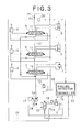
- a fail-safe valve (electromagnetic switching valve) 22 of an electromagnetic switching type adapted to switch between the ordinary position x and the fail-safe position y in accordance with an electric signal is disposed in the pump control line 18 instead of the hydraulic pilot switching type fail-safe valve 19 described in the first embodiment.
- the switching of the fail-safe valve 22 is controlled by means of a controller 23.
- a failure detector 24 for detecting the occurrence of failure (output failure) such as wire breaking in an output signal system for the regulator control valve 15 on the basis of for example a decrease of voltage or current.
- failure detector 24 detects the occurrence of failure (output failure) such as wire breaking in an output signal system for the regulator control valve 15 on the basis of for example a decrease of voltage or current.
- the fail-safe valve 22 in the event of failure of the regulator control valve 15, the fail-safe valve 22 also switches from the ordinary position x to the fail-safe position y, whereby the oil pressure P1 from the auxiliary hydraulic pump 17 is fed as a pump controlling oil pressure to the pump regulator 14 and the discharge amount of the main hydraulic pump 10 is set and fixed to maximum.
- the oil pressure from the auxiliary hydraulic pump 17 is not only fed as a primary pressure to the regulator control valve 15 but also fed as a pump controlling oil pressure to the pump regulator 14 in the switched state of the fail-safe valve 22 (19 in the first embodiment) to the fail-safe position y.
- the oil pressure P1 is fed from the auxiliary hydraulic pump 17 to the pump regulator 14 upon failure of the regulator control valve 15.
- a negative control pressure P3 is fed as a pump controlling oil pressure to the pump regulator 14 upon failure of the regulator control valve 15.
- a throttle 25 is provided on the most downstream side of the center bypass line 12 and the pressure (negative control pressure) P3 which is developed on the inlet side of the throttle 25 in accordance with a bleed-off flow rate is detected by a pressure sensor 26 and is inputted to the controller 23.
- the controller 23 judges that the higher the negative control pressure P3 is, the smaller the flow rate required of the actuators would be, and then outputs a control signal in the direction to decrease the pump discharge amount to the regulator control valve 15.
- this third embodiment is different from the second embodiment in that, upon switching of the fail-safe valve 22 to the fail-safe position y, not the oil pressure P1 in the auxiliary hydraulic pump 17, but the negative control pressure P3 developed by the throttle 25 is fed to the pump regulator through a negative control pressure output line 27 and the fail-safe valve 22.
- this fourth embodiment illustrated in Fig. 4 premises the positive control system wherein the operation amounts of the remote control valves 4 to 6 are detected by sensors and fed to the controller 23, then the pump discharge amount is controlled in accordance with the detected operation amounts.
- pilot pressures corresponding to the operation amount of the remote control valves is selected by a high-order selection in multi-stage shuttle valves 28, 29, 30 and 31 and the selected pilot pressure (positive control pressure) P4 is fed as a pump controlling oil pressure to the pump regulator 14 through a positive control pressure output line 32 and the fail-safe valve 22.
- the same pump control based on the positive control system as in the normal condition can be also ensured in the failed condition and it is possible to continue the same actuator operation as in the normal condition.
- the bleed-off passages 11 are disposed in the control valves 7 to 9 for controlling the operations of the hydraulic actuators each independently, the bleed-off passages 11 in the control valves 7 to 9 being tandem connected to the tank T by means of the center bypass line 12, the throttle 25 is provided on the most downstream side of the center bypass line 12, the controller 23 as controller sends a control signal which causes the discharge amount of the hydraulic pump 10 to be changed to the regulator control valve 15 in accordance with a negative control pressure developed by the throttle 25, and in the switched state of the fail-safe valve 22 to the fail-safe position y the aforesaid negative control pressure is fed as a pump controlling oil pressure to the pump regulator 14.
- the controller 23 as controller sends a control signal which causes the discharge amount of the hydraulic pump 10 to be changed to the regulator control valve 15 in accordance with a positive control pressure developed by the operation of the remote control valves 4 to 6 as operating means, and in the switched state of the fail-safe valve 22 to the fail-safe position y, the aforesaid positive control pressure is fed as a pump controlling oil pressure to the pump regulator 14.
- a negative or positive control pressure is utilized as a pump controlling oil pressure, so that the control of the pump discharge amount based on the negative or positive control system can be also maintained in the failed condition. That is, the same pump control and actuator control as in the normal condition can be also maintained in the failed condition.
- a switching valve wherein a side spool adapted for a stroke operation integrally with a main spool is provided on one side of the main spool.
- Side by-path 34 adapted to open when the remote control valves 4 to 6 are in the neutral position and close when those valves operate are formed respectively in the respective side spools 33.
- the side by-path 34 are tandem connected to the auxiliary hydraulic pump 17 and the tank T by means of a side by-path line 35.
- a throttle 36 for developing pump pressure is provided on the discharge side of the auxiliary hydraulic pump 17 in the side by-path line 35.
- a pump controlling oil pressure line 37 connected to the outlet side of the throttle 36 is connected to the fail-safe valve 22.
- the pressure P5 is applied as a pump controlling oil pressure to the pump regulator 14 through the fail-safe valve 22.
- the operation (required pump discharge amount) can be also ensured in the failed condition.
- the side spools 33 provided with side by-path 34 adapted to close upon the operation of the control valves 7 to 9 are provided in the control valves 7 to 9 which control the operations of hydraulic actuators each independently, the side by-path line 35 which connects the side by-path 34 in the control valves 7 to 9 tandem to the oil pressure source and the tank T is provided, and in the switched state of the fail-safe valve 22 to the fail-safe position y the oil pressure developed in the side by-path line 35 upon the operation of the control valves 7 to 9 is fed as a pump controlling oil pressure to the pump regulator 14.
Landscapes
- Engineering & Computer Science (AREA)
- General Engineering & Computer Science (AREA)
- Mining & Mineral Resources (AREA)
- Civil Engineering (AREA)
- Structural Engineering (AREA)
- Fluid Mechanics (AREA)
- Physics & Mathematics (AREA)
- Chemical & Material Sciences (AREA)
- Analytical Chemistry (AREA)
- Mechanical Engineering (AREA)
- Fluid-Pressure Circuits (AREA)
- Operation Control Of Excavators (AREA)
- Lifting Devices For Agricultural Implements (AREA)
Abstract
Description
Claims (7)
- A hydraulic control system for a working machine, comprising:hydraulic actuators;a variable capacity hydraulic pump as an oil pressure source for said hydraulic actuators;a pump regulator for controlling a discharge amount of said hydraulic pump;an electromagnetic proportional regulator control valve for controlling an operation of said pump regulator;a controller adapted to send a control signal for changing the discharge amount of said hydraulic pump to said regulator control valve in accordance with an operation amount of an operating means, wherein a secondary pressure in said regulator control valve being fed as a controlling oil pressure to said pump regulator in accordance with said control signal; anda fail-safe valve disposed in a pump control line joining said pump regulator and said regulator control valve, said fail-safe valve having an ordinary position for sending the secondary pressure in said regulator control valve as a controlling oil pressure to said pump regulator and a fail-safe position for sending an oil pressure from a path other than said regulator control valve as a pump controlling oil pressure to said pump regulator in such a manner that a predetermined pump discharge amount is ensured, said fail-safe valve being configured so as to switch from said ordinary position to said fail-safe position in accordance with a failure signal indicative of failure in operation of said regulator control valve.
- The hydraulic control system for a working machine according to claim 1, wherein said fail-safe valve is configured as a hydraulic pilot switching valve with a hydraulic pilot port adapted to switch between said ordinary position and said fail-safe position on the basis of a pilot pressure introduced into said hydraulic pilot port and a spring force resisting to said pilot pressure, the secondary pressure in said regulator control valve is introduced into the hydraulic pilot port of said fail-safe valve, a signal is issued as the failure signal when said secondary pressure drops below a preset value, and in accordance with said signal the fail-safe valve switches from said ordinary position to said fail-safe position by said spring force.
- The hydraulic control system for a working machine according to claim 1, wherein an electromagnetic switching valve is used as said fail-safe valve, a failure detector is further provided for detecting an output failure of the control signal outputted from said controller to said regulator control valve, and when the output failure is detected by said failure detector, said controller switches said fail-safe valve to said fail-safe position.
- The hydraulic control system for a working machine according to claim 1, further comprising an auxiliary hydraulic pump, pressure oil from said auxiliary hydraulic pump being fed as a primary pressure to said regulator control valve and also fed as a controlling oil pressure to said pump regulator in a switched state of said fail-safe valve to said fail-safe position.
- The hydraulic control system for a working machine according to claim 1, wherein bleed-off path is formed respectively in each of control valves for controlling operations of said hydraulic actuators independently, a throttle is provided on the most downstream side of a center bypass line for connecting said bleed-off path in each of said control valves tandem to a tank, and said controller being configured so as to send a control signal for changing the discharge amount of said hydraulic pump to said regulator control valve in accordance with a negative control pressure developed by said throttle and being configured so that said negative control pressure is fed as a controlling oil pressure to said pump regulator in a switched state of said fail-safe valve to said fail-safe position.
- The hydraulic control system for a working machine according to claim 1, wherein said controller is configured so as to send a control signal for changing the discharge amount of said hydraulic pump to said regulator control valve in accordance with a positive control pressure developed by an operation of a remote control valve as the operating means and is configured so that said positive control pressure is fed as a controlling oil pressure to said pump regulator in a switched state of said fail-safe valve to said fail-safe position.
- The hydraulic control system for a working machine according to claim 1, further comprising:a side spool having a side by-path provided with each of control valves for controlling operations of said hydraulic actuators independently, said side by-path being adapted to be closed upon an operation of said each of control valves; anda side by-path line for connecting said side by-path in said each of control valves tandem to said oil pressure source and a tank, wherein, in a switched state of said fail-safe valve to said fail-safe position, an oil pressure developed in said side by-path line by an operation of any of said control valves is fed as a controlling oil pressure to said pump regulator.
Applications Claiming Priority (2)
| Application Number | Priority Date | Filing Date | Title |
|---|---|---|---|
| JP2004078856A JP4453411B2 (en) | 2004-03-18 | 2004-03-18 | Hydraulic control device for work machine |
| JP2004078856 | 2004-03-18 |
Publications (3)
| Publication Number | Publication Date |
|---|---|
| EP1577564A2 true EP1577564A2 (en) | 2005-09-21 |
| EP1577564A3 EP1577564A3 (en) | 2005-12-28 |
| EP1577564B1 EP1577564B1 (en) | 2008-02-13 |
Family
ID=34836580
Family Applications (1)
| Application Number | Title | Priority Date | Filing Date |
|---|---|---|---|
| EP05102016A Expired - Lifetime EP1577564B1 (en) | 2004-03-18 | 2005-03-15 | Hydraulic control system for working machine |
Country Status (6)
| Country | Link |
|---|---|
| US (2) | US7284371B2 (en) |
| EP (1) | EP1577564B1 (en) |
| JP (1) | JP4453411B2 (en) |
| CN (1) | CN100441786C (en) |
| AT (1) | ATE386214T1 (en) |
| DE (1) | DE602005004683T2 (en) |
Families Citing this family (26)
| Publication number | Priority date | Publication date | Assignee | Title |
|---|---|---|---|---|
| KR100752115B1 (en) * | 2004-12-30 | 2007-08-24 | 두산인프라코어 주식회사 | Hydraulic pump control system for an excavator |
| JP5015880B2 (en) * | 2008-08-25 | 2012-08-29 | 住友建機株式会社 | Pump control circuit for construction machinery |
| FR2944048A1 (en) | 2009-04-02 | 2010-10-08 | Geoservices Equipements | INTERVENTION DEVICE IN A FLUID OPERATING WELL, OPERATING PLANT AND ASSOCIATED METHOD |
| US8661804B2 (en) * | 2009-12-11 | 2014-03-04 | Caterpillar Inc. | Control system for swashplate pump |
| DE102010053811A1 (en) * | 2010-12-08 | 2012-06-14 | Moog Gmbh | Fault-proof actuation system |
| CN102190247B (en) * | 2011-05-11 | 2013-03-27 | 三一汽车起重机械有限公司 | Hydraulic pilot control system and hydraulic pilot crane provided with same |
| CN103620233B (en) * | 2011-06-27 | 2016-04-20 | 沃尔沃建造设备有限公司 | For the hydraulic control valve of construction plant |
| JP5778058B2 (en) * | 2012-03-09 | 2015-09-16 | 住友建機株式会社 | Construction machine control device and control method thereof |
| CN102720710B (en) * | 2012-06-26 | 2015-09-16 | 中联重科股份有限公司 | Hydraulic system, control method of hydraulic system and construction machinery |
| CN102734242B (en) * | 2012-07-13 | 2015-05-27 | 三一汽车制造有限公司 | Engineering machinery, hydraulic control system and method of multi-execution mechanism |
| CN102937085A (en) * | 2012-11-16 | 2013-02-20 | 无锡汇虹机械制造有限公司 | Displacement adjusting method for positive-flow hydraulic pump of excavator |
| CN103899599B (en) * | 2014-04-24 | 2016-04-27 | 徐州重型机械有限公司 | A kind of controlling method of instant flow matches, system and hoist |
| DE102014208019B4 (en) | 2014-04-29 | 2025-01-30 | Robert Bosch Gmbh | Hydraulic control arrangement for several actuators |
| JP2016011633A (en) * | 2014-06-30 | 2016-01-21 | 川崎重工業株式会社 | Hydraulic drive system with fail-safe |
| JP6333713B2 (en) * | 2014-12-15 | 2018-05-30 | 株式会社Kcm | Hydraulic drive system |
| CN104563856B (en) * | 2015-01-15 | 2016-08-24 | 山河智能装备股份有限公司 | Fast discharge of rotary drill rig control system |
| CN105134696A (en) * | 2015-09-21 | 2015-12-09 | 成都丝迈尔科技有限公司 | Universal type wireless switch executor used for hydraulic device |
| KR102388136B1 (en) * | 2016-05-18 | 2022-04-19 | 현대두산인프라코어(주) | Safety system for construction machinery |
| US10487855B2 (en) * | 2016-09-29 | 2019-11-26 | Deere & Company | Electro-hydraulic system with negative flow control |
| US10233951B2 (en) * | 2016-10-05 | 2019-03-19 | Caterpillar Inc. | Method to detect uncommanded spool valve positioning and stop fluid flow to hydraulic actuators |
| JP6726127B2 (en) * | 2017-03-30 | 2020-07-22 | 川崎重工業株式会社 | Hydraulic system |
| JP2018168977A (en) * | 2017-03-30 | 2018-11-01 | 川崎重工業株式会社 | Hydraulic system |
| JP6815267B2 (en) * | 2017-04-18 | 2021-01-20 | 川崎重工業株式会社 | Hydraulic system |
| JP6845736B2 (en) * | 2017-04-28 | 2021-03-24 | 川崎重工業株式会社 | Hydraulic drive system |
| CN107387473B (en) * | 2017-08-16 | 2023-10-10 | 冯广建 | Tandem channel-borrowing type multipath hydraulic control device |
| JP7332423B2 (en) * | 2019-10-16 | 2023-08-23 | ナブテスコ株式会社 | HYDRAULIC SYSTEM, CONSTRUCTION MACHINE, HYDRAULIC CONTROL METHOD, AND PROGRAM |
Family Cites Families (14)
| Publication number | Priority date | Publication date | Assignee | Title |
|---|---|---|---|---|
| US4197705A (en) * | 1978-05-30 | 1980-04-15 | General Signal Corporation | Hydraulic control system |
| US4408453A (en) * | 1981-01-16 | 1983-10-11 | General Signal Corporation | Hydraulic control system |
| JPS58193906A (en) | 1982-05-06 | 1983-11-11 | Hitachi Constr Mach Co Ltd | Hydraulic circuit for construction machine |
| JPH0721282B2 (en) * | 1986-03-22 | 1995-03-08 | 油研工業株式会社 | Variable displacement pump |
| US4823552A (en) * | 1987-04-29 | 1989-04-25 | Vickers, Incorporated | Failsafe electrohydraulic control system for variable displacement pump |
| JP3445817B2 (en) | 1993-11-11 | 2003-09-08 | 日立建機株式会社 | Hydraulic drive for construction machinery |
| US5758499A (en) * | 1995-03-03 | 1998-06-02 | Hitachi Construction Machinery Co., Ltd. | Hydraulic control system |
| JPH0978635A (en) * | 1995-09-18 | 1997-03-25 | Yutani Heavy Ind Ltd | Hydraulic combined flow circuit |
| JPH1054370A (en) | 1996-08-12 | 1998-02-24 | Hitachi Constr Mach Co Ltd | Diagnosis device for hydraulic pump of work machine |
| JPH11125205A (en) * | 1997-10-23 | 1999-05-11 | Hitachi Constr Mach Co Ltd | Hydraulic drive device for hydraulic working machine |
| JPH11303809A (en) * | 1998-04-20 | 1999-11-02 | Komatsu Ltd | Pump control device for hydraulic drive machine |
| JP3625149B2 (en) * | 1999-03-31 | 2005-03-02 | コベルコ建機株式会社 | Hydraulic control circuit for construction machinery |
| JP3574782B2 (en) * | 2000-10-13 | 2004-10-06 | 新キャタピラー三菱株式会社 | Work machine control device |
| JP2003049810A (en) * | 2001-08-07 | 2003-02-21 | Hitachi Constr Mach Co Ltd | Pressure oil energy recovering device and construction machine with the same |
-
2004
- 2004-03-18 JP JP2004078856A patent/JP4453411B2/en not_active Expired - Fee Related
-
2005
- 2005-03-14 US US11/078,340 patent/US7284371B2/en not_active Expired - Lifetime
- 2005-03-15 DE DE602005004683T patent/DE602005004683T2/en not_active Expired - Lifetime
- 2005-03-15 AT AT05102016T patent/ATE386214T1/en not_active IP Right Cessation
- 2005-03-15 EP EP05102016A patent/EP1577564B1/en not_active Expired - Lifetime
- 2005-03-17 CN CNB2005100551503A patent/CN100441786C/en not_active Expired - Fee Related
-
2007
- 2007-07-26 US US11/828,920 patent/US20080017022A1/en not_active Abandoned
Also Published As
| Publication number | Publication date |
|---|---|
| JP2005265062A (en) | 2005-09-29 |
| EP1577564A3 (en) | 2005-12-28 |
| EP1577564B1 (en) | 2008-02-13 |
| US7284371B2 (en) | 2007-10-23 |
| JP4453411B2 (en) | 2010-04-21 |
| US20050204912A1 (en) | 2005-09-22 |
| US20080017022A1 (en) | 2008-01-24 |
| CN100441786C (en) | 2008-12-10 |
| DE602005004683T2 (en) | 2008-06-12 |
| DE602005004683D1 (en) | 2008-03-27 |
| CN1670317A (en) | 2005-09-21 |
| ATE386214T1 (en) | 2008-03-15 |
Similar Documents
| Publication | Publication Date | Title |
|---|---|---|
| US7284371B2 (en) | Hydraulic control system for working machine | |
| US7594396B2 (en) | Hydraulic controller for working machine | |
| EP1577563B1 (en) | Hydraulic control device for working machine | |
| US10655647B2 (en) | Hydraulic drive system for construction machine | |
| US20140090368A1 (en) | Hydraulic system for construction machinery | |
| JP2011256814A (en) | Pump discharge amount control circuit for construction machine | |
| KR100559291B1 (en) | Hydraulic Circuit for Heavy Equipment Option | |
| KR100749316B1 (en) | Hydraulic circuit | |
| US20040261405A1 (en) | Hydraulic circuit for heavy equipment option apparatus using boom confluence spool | |
| JP7758557B2 (en) | Hydraulic control systems for work machines | |
| JP2004360898A (en) | Hydraulic control device for working machine | |
| JP4668445B2 (en) | Hydraulic control equipment, construction machinery and hydraulic excavators | |
| US9114831B2 (en) | Actuator control system | |
| JP6577431B2 (en) | Hydraulic drive unit for construction machinery | |
| JP5366485B2 (en) | Hydraulic control equipment for construction machinery | |
| JP2000220602A (en) | Hydraulic circuit for construction machine | |
| JP2004092826A (en) | Operating device of hydraulic drive system | |
| JP3281427B2 (en) | Hydraulic control device for construction machinery | |
| KR20030058377A (en) | apparatus for controlling hydraulic pumps in an excavator | |
| WO2018178961A1 (en) | Hydraulic system | |
| JPH06116985A (en) | Hydraulic control equipment for construction machinery | |
| KR20140109873A (en) | Hydraulic system for construction equipment |
Legal Events
| Date | Code | Title | Description |
|---|---|---|---|
| PUAI | Public reference made under article 153(3) epc to a published international application that has entered the european phase |
Free format text: ORIGINAL CODE: 0009012 |
|
| AK | Designated contracting states |
Kind code of ref document: A2 Designated state(s): AT BE BG CH CY CZ DE DK EE ES FI FR GB GR HU IE IS IT LI LT LU MC NL PL PT RO SE SI SK TR |
|
| AX | Request for extension of the european patent |
Extension state: AL BA HR LV MK YU |
|
| PUAL | Search report despatched |
Free format text: ORIGINAL CODE: 0009013 |
|
| AK | Designated contracting states |
Kind code of ref document: A3 Designated state(s): AT BE BG CH CY CZ DE DK EE ES FI FR GB GR HU IE IS IT LI LT LU MC NL PL PT RO SE SI SK TR |
|
| AX | Request for extension of the european patent |
Extension state: AL BA HR LV MK YU |
|
| RIC1 | Information provided on ipc code assigned before grant |
Ipc: 7F 15B 11/16 A Ipc: 7F 04B 49/22 B Ipc: 7F 04B 49/10 B Ipc: 7F 04B 49/00 B Ipc: 7E 02F 9/22 B Ipc: 7F 15B 20/00 B |
|
| 17P | Request for examination filed |
Effective date: 20060612 |
|
| 17Q | First examination report despatched |
Effective date: 20060724 |
|
| AKX | Designation fees paid |
Designated state(s): AT BE BG CH CY CZ DE DK EE ES FI FR GB GR HU IE IS IT LI LT LU MC NL PL PT RO SE SI SK TR |
|
| GRAP | Despatch of communication of intention to grant a patent |
Free format text: ORIGINAL CODE: EPIDOSNIGR1 |
|
| RIN1 | Information on inventor provided before grant (corrected) |
Inventor name: TOJI, YUTAKA Inventor name: YAMAZAKI, YOICHIROC/O KOBELCO CONSTRUCTION Inventor name: OKA, HIDEKAZU |
|
| GRAS | Grant fee paid |
Free format text: ORIGINAL CODE: EPIDOSNIGR3 |
|
| GRAA | (expected) grant |
Free format text: ORIGINAL CODE: 0009210 |
|
| AK | Designated contracting states |
Kind code of ref document: B1 Designated state(s): AT BE BG CH CY CZ DE DK EE ES FI FR GB GR HU IE IS IT LI LT LU MC NL PL PT RO SE SI SK TR |
|
| REG | Reference to a national code |
Ref country code: GB Ref legal event code: FG4D |
|
| REG | Reference to a national code |
Ref country code: CH Ref legal event code: EP |
|
| REG | Reference to a national code |
Ref country code: IE Ref legal event code: FG4D |
|
| REF | Corresponds to: |
Ref document number: 602005004683 Country of ref document: DE Date of ref document: 20080327 Kind code of ref document: P |
|
| PG25 | Lapsed in a contracting state [announced via postgrant information from national office to epo] |
Ref country code: IS Free format text: LAPSE BECAUSE OF FAILURE TO SUBMIT A TRANSLATION OF THE DESCRIPTION OR TO PAY THE FEE WITHIN THE PRESCRIBED TIME-LIMIT Effective date: 20080613 Ref country code: FI Free format text: LAPSE BECAUSE OF FAILURE TO SUBMIT A TRANSLATION OF THE DESCRIPTION OR TO PAY THE FEE WITHIN THE PRESCRIBED TIME-LIMIT Effective date: 20080213 Ref country code: ES Free format text: LAPSE BECAUSE OF FAILURE TO SUBMIT A TRANSLATION OF THE DESCRIPTION OR TO PAY THE FEE WITHIN THE PRESCRIBED TIME-LIMIT Effective date: 20080524 |
|
| ET | Fr: translation filed | ||
| NLV1 | Nl: lapsed or annulled due to failure to fulfill the requirements of art. 29p and 29m of the patents act | ||
| PG25 | Lapsed in a contracting state [announced via postgrant information from national office to epo] |
Ref country code: AT Free format text: LAPSE BECAUSE OF FAILURE TO SUBMIT A TRANSLATION OF THE DESCRIPTION OR TO PAY THE FEE WITHIN THE PRESCRIBED TIME-LIMIT Effective date: 20080213 |
|
| PG25 | Lapsed in a contracting state [announced via postgrant information from national office to epo] |
Ref country code: PL Free format text: LAPSE BECAUSE OF FAILURE TO SUBMIT A TRANSLATION OF THE DESCRIPTION OR TO PAY THE FEE WITHIN THE PRESCRIBED TIME-LIMIT Effective date: 20080213 Ref country code: BE Free format text: LAPSE BECAUSE OF FAILURE TO SUBMIT A TRANSLATION OF THE DESCRIPTION OR TO PAY THE FEE WITHIN THE PRESCRIBED TIME-LIMIT Effective date: 20080213 Ref country code: SI Free format text: LAPSE BECAUSE OF FAILURE TO SUBMIT A TRANSLATION OF THE DESCRIPTION OR TO PAY THE FEE WITHIN THE PRESCRIBED TIME-LIMIT Effective date: 20080213 |
|
| PG25 | Lapsed in a contracting state [announced via postgrant information from national office to epo] |
Ref country code: CZ Free format text: LAPSE BECAUSE OF FAILURE TO SUBMIT A TRANSLATION OF THE DESCRIPTION OR TO PAY THE FEE WITHIN THE PRESCRIBED TIME-LIMIT Effective date: 20080213 Ref country code: DK Free format text: LAPSE BECAUSE OF FAILURE TO SUBMIT A TRANSLATION OF THE DESCRIPTION OR TO PAY THE FEE WITHIN THE PRESCRIBED TIME-LIMIT Effective date: 20080213 Ref country code: MC Free format text: LAPSE BECAUSE OF NON-PAYMENT OF DUE FEES Effective date: 20080331 Ref country code: NL Free format text: LAPSE BECAUSE OF FAILURE TO SUBMIT A TRANSLATION OF THE DESCRIPTION OR TO PAY THE FEE WITHIN THE PRESCRIBED TIME-LIMIT Effective date: 20080213 Ref country code: PT Free format text: LAPSE BECAUSE OF FAILURE TO SUBMIT A TRANSLATION OF THE DESCRIPTION OR TO PAY THE FEE WITHIN THE PRESCRIBED TIME-LIMIT Effective date: 20080714 Ref country code: SE Free format text: LAPSE BECAUSE OF FAILURE TO SUBMIT A TRANSLATION OF THE DESCRIPTION OR TO PAY THE FEE WITHIN THE PRESCRIBED TIME-LIMIT Effective date: 20080513 Ref country code: SK Free format text: LAPSE BECAUSE OF FAILURE TO SUBMIT A TRANSLATION OF THE DESCRIPTION OR TO PAY THE FEE WITHIN THE PRESCRIBED TIME-LIMIT Effective date: 20080213 |
|
| PG25 | Lapsed in a contracting state [announced via postgrant information from national office to epo] |
Ref country code: RO Free format text: LAPSE BECAUSE OF FAILURE TO SUBMIT A TRANSLATION OF THE DESCRIPTION OR TO PAY THE FEE WITHIN THE PRESCRIBED TIME-LIMIT Effective date: 20080213 |
|
| PLBE | No opposition filed within time limit |
Free format text: ORIGINAL CODE: 0009261 |
|
| STAA | Information on the status of an ep patent application or granted ep patent |
Free format text: STATUS: NO OPPOSITION FILED WITHIN TIME LIMIT |
|
| 26N | No opposition filed |
Effective date: 20081114 |
|
| PG25 | Lapsed in a contracting state [announced via postgrant information from national office to epo] |
Ref country code: EE Free format text: LAPSE BECAUSE OF FAILURE TO SUBMIT A TRANSLATION OF THE DESCRIPTION OR TO PAY THE FEE WITHIN THE PRESCRIBED TIME-LIMIT Effective date: 20080213 Ref country code: IE Free format text: LAPSE BECAUSE OF NON-PAYMENT OF DUE FEES Effective date: 20080317 Ref country code: LT Free format text: LAPSE BECAUSE OF FAILURE TO SUBMIT A TRANSLATION OF THE DESCRIPTION OR TO PAY THE FEE WITHIN THE PRESCRIBED TIME-LIMIT Effective date: 20080213 |
|
| PG25 | Lapsed in a contracting state [announced via postgrant information from national office to epo] |
Ref country code: BG Free format text: LAPSE BECAUSE OF FAILURE TO SUBMIT A TRANSLATION OF THE DESCRIPTION OR TO PAY THE FEE WITHIN THE PRESCRIBED TIME-LIMIT Effective date: 20080513 |
|
| PG25 | Lapsed in a contracting state [announced via postgrant information from national office to epo] |
Ref country code: CY Free format text: LAPSE BECAUSE OF FAILURE TO SUBMIT A TRANSLATION OF THE DESCRIPTION OR TO PAY THE FEE WITHIN THE PRESCRIBED TIME-LIMIT Effective date: 20080213 |
|
| REG | Reference to a national code |
Ref country code: CH Ref legal event code: PL |
|
| PG25 | Lapsed in a contracting state [announced via postgrant information from national office to epo] |
Ref country code: CH Free format text: LAPSE BECAUSE OF NON-PAYMENT OF DUE FEES Effective date: 20090331 Ref country code: LI Free format text: LAPSE BECAUSE OF NON-PAYMENT OF DUE FEES Effective date: 20090331 |
|
| PG25 | Lapsed in a contracting state [announced via postgrant information from national office to epo] |
Ref country code: HU Free format text: LAPSE BECAUSE OF FAILURE TO SUBMIT A TRANSLATION OF THE DESCRIPTION OR TO PAY THE FEE WITHIN THE PRESCRIBED TIME-LIMIT Effective date: 20080814 Ref country code: LU Free format text: LAPSE BECAUSE OF NON-PAYMENT OF DUE FEES Effective date: 20080315 |
|
| PG25 | Lapsed in a contracting state [announced via postgrant information from national office to epo] |
Ref country code: TR Free format text: LAPSE BECAUSE OF FAILURE TO SUBMIT A TRANSLATION OF THE DESCRIPTION OR TO PAY THE FEE WITHIN THE PRESCRIBED TIME-LIMIT Effective date: 20080213 |
|
| PG25 | Lapsed in a contracting state [announced via postgrant information from national office to epo] |
Ref country code: GR Free format text: LAPSE BECAUSE OF FAILURE TO SUBMIT A TRANSLATION OF THE DESCRIPTION OR TO PAY THE FEE WITHIN THE PRESCRIBED TIME-LIMIT Effective date: 20080514 |
|
| REG | Reference to a national code |
Ref country code: FR Ref legal event code: PLFP Year of fee payment: 12 |
|
| REG | Reference to a national code |
Ref country code: FR Ref legal event code: PLFP Year of fee payment: 13 |
|
| REG | Reference to a national code |
Ref country code: FR Ref legal event code: PLFP Year of fee payment: 14 |
|
| PGFP | Annual fee paid to national office [announced via postgrant information from national office to epo] |
Ref country code: FR Payment date: 20230208 Year of fee payment: 19 |
|
| PGFP | Annual fee paid to national office [announced via postgrant information from national office to epo] |
Ref country code: IT Payment date: 20230213 Year of fee payment: 19 Ref country code: GB Payment date: 20230202 Year of fee payment: 19 Ref country code: DE Payment date: 20230131 Year of fee payment: 19 |
|
| REG | Reference to a national code |
Ref country code: DE Ref legal event code: R119 Ref document number: 602005004683 Country of ref document: DE |
|
| GBPC | Gb: european patent ceased through non-payment of renewal fee |
Effective date: 20240315 |
|
| PG25 | Lapsed in a contracting state [announced via postgrant information from national office to epo] |
Ref country code: DE Free format text: LAPSE BECAUSE OF NON-PAYMENT OF DUE FEES Effective date: 20241001 |
|
| PG25 | Lapsed in a contracting state [announced via postgrant information from national office to epo] |
Ref country code: GB Free format text: LAPSE BECAUSE OF NON-PAYMENT OF DUE FEES Effective date: 20240315 |
|
| PG25 | Lapsed in a contracting state [announced via postgrant information from national office to epo] |
Ref country code: FR Free format text: LAPSE BECAUSE OF NON-PAYMENT OF DUE FEES Effective date: 20240331 |
|
| PG25 | Lapsed in a contracting state [announced via postgrant information from national office to epo] |
Ref country code: GB Free format text: LAPSE BECAUSE OF NON-PAYMENT OF DUE FEES Effective date: 20240315 Ref country code: FR Free format text: LAPSE BECAUSE OF NON-PAYMENT OF DUE FEES Effective date: 20240331 Ref country code: DE Free format text: LAPSE BECAUSE OF NON-PAYMENT OF DUE FEES Effective date: 20241001 |
|
| PG25 | Lapsed in a contracting state [announced via postgrant information from national office to epo] |
Ref country code: IT Free format text: LAPSE BECAUSE OF NON-PAYMENT OF DUE FEES Effective date: 20240315 |