EP1577537A2 - Intake manifold for mixing and supplying air and exhaust gas recirculation - Google Patents
Intake manifold for mixing and supplying air and exhaust gas recirculation Download PDFInfo
- Publication number
- EP1577537A2 EP1577537A2 EP05101633A EP05101633A EP1577537A2 EP 1577537 A2 EP1577537 A2 EP 1577537A2 EP 05101633 A EP05101633 A EP 05101633A EP 05101633 A EP05101633 A EP 05101633A EP 1577537 A2 EP1577537 A2 EP 1577537A2
- Authority
- EP
- European Patent Office
- Prior art keywords
- egr
- wall
- manifold
- valve
- chamber
- Prior art date
- Legal status (The legal status is an assumption and is not a legal conclusion. Google has not performed a legal analysis and makes no representation as to the accuracy of the status listed.)
- Withdrawn
Links
Images


Classifications
-
- F—MECHANICAL ENGINEERING; LIGHTING; HEATING; WEAPONS; BLASTING
- F02—COMBUSTION ENGINES; HOT-GAS OR COMBUSTION-PRODUCT ENGINE PLANTS
- F02M—SUPPLYING COMBUSTION ENGINES IN GENERAL WITH COMBUSTIBLE MIXTURES OR CONSTITUENTS THEREOF
- F02M35/00—Combustion-air cleaners, air intakes, intake silencers, or induction systems specially adapted for, or arranged on, internal-combustion engines
- F02M35/10—Air intakes; Induction systems
- F02M35/10209—Fluid connections to the air intake system; their arrangement of pipes, valves or the like
- F02M35/10222—Exhaust gas recirculation [EGR]; Positive crankcase ventilation [PCV]; Additional air admission, lubricant or fuel vapour admission
-
- F—MECHANICAL ENGINEERING; LIGHTING; HEATING; WEAPONS; BLASTING
- F02—COMBUSTION ENGINES; HOT-GAS OR COMBUSTION-PRODUCT ENGINE PLANTS
- F02M—SUPPLYING COMBUSTION ENGINES IN GENERAL WITH COMBUSTIBLE MIXTURES OR CONSTITUENTS THEREOF
- F02M26/00—Engine-pertinent apparatus for adding exhaust gases to combustion-air, main fuel or fuel-air mixture, e.g. by exhaust gas recirculation [EGR] systems
- F02M26/13—Arrangement or layout of EGR passages, e.g. in relation to specific engine parts or for incorporation of accessories
- F02M26/17—Arrangement or layout of EGR passages, e.g. in relation to specific engine parts or for incorporation of accessories in relation to the intake system
- F02M26/19—Means for improving the mixing of air and recirculated exhaust gases, e.g. venturis or multiple openings to the intake system
-
- F—MECHANICAL ENGINEERING; LIGHTING; HEATING; WEAPONS; BLASTING
- F02—COMBUSTION ENGINES; HOT-GAS OR COMBUSTION-PRODUCT ENGINE PLANTS
- F02M—SUPPLYING COMBUSTION ENGINES IN GENERAL WITH COMBUSTIBLE MIXTURES OR CONSTITUENTS THEREOF
- F02M26/00—Engine-pertinent apparatus for adding exhaust gases to combustion-air, main fuel or fuel-air mixture, e.g. by exhaust gas recirculation [EGR] systems
- F02M26/13—Arrangement or layout of EGR passages, e.g. in relation to specific engine parts or for incorporation of accessories
- F02M26/17—Arrangement or layout of EGR passages, e.g. in relation to specific engine parts or for incorporation of accessories in relation to the intake system
- F02M26/21—Arrangement or layout of EGR passages, e.g. in relation to specific engine parts or for incorporation of accessories in relation to the intake system with EGR valves located at or near the connection to the intake system
-
- F—MECHANICAL ENGINEERING; LIGHTING; HEATING; WEAPONS; BLASTING
- F02—COMBUSTION ENGINES; HOT-GAS OR COMBUSTION-PRODUCT ENGINE PLANTS
- F02M—SUPPLYING COMBUSTION ENGINES IN GENERAL WITH COMBUSTIBLE MIXTURES OR CONSTITUENTS THEREOF
- F02M26/00—Engine-pertinent apparatus for adding exhaust gases to combustion-air, main fuel or fuel-air mixture, e.g. by exhaust gas recirculation [EGR] systems
- F02M26/13—Arrangement or layout of EGR passages, e.g. in relation to specific engine parts or for incorporation of accessories
- F02M26/38—Arrangement or layout of EGR passages, e.g. in relation to specific engine parts or for incorporation of accessories with two or more EGR valves disposed in parallel
-
- F—MECHANICAL ENGINEERING; LIGHTING; HEATING; WEAPONS; BLASTING
- F02—COMBUSTION ENGINES; HOT-GAS OR COMBUSTION-PRODUCT ENGINE PLANTS
- F02M—SUPPLYING COMBUSTION ENGINES IN GENERAL WITH COMBUSTIBLE MIXTURES OR CONSTITUENTS THEREOF
- F02M26/00—Engine-pertinent apparatus for adding exhaust gases to combustion-air, main fuel or fuel-air mixture, e.g. by exhaust gas recirculation [EGR] systems
- F02M26/13—Arrangement or layout of EGR passages, e.g. in relation to specific engine parts or for incorporation of accessories
- F02M26/41—Arrangement or layout of EGR passages, e.g. in relation to specific engine parts or for incorporation of accessories characterised by the arrangement of the recirculation passage in relation to the engine, e.g. to cylinder heads, liners, spark plugs or manifolds; characterised by the arrangement of the recirculation passage in relation to specially adapted combustion chambers
-
- F—MECHANICAL ENGINEERING; LIGHTING; HEATING; WEAPONS; BLASTING
- F02—COMBUSTION ENGINES; HOT-GAS OR COMBUSTION-PRODUCT ENGINE PLANTS
- F02M—SUPPLYING COMBUSTION ENGINES IN GENERAL WITH COMBUSTIBLE MIXTURES OR CONSTITUENTS THEREOF
- F02M35/00—Combustion-air cleaners, air intakes, intake silencers, or induction systems specially adapted for, or arranged on, internal-combustion engines
- F02M35/10—Air intakes; Induction systems
- F02M35/10242—Devices or means connected to or integrated into air intakes; Air intakes combined with other engine or vehicle parts
- F02M35/10255—Arrangements of valves; Multi-way valves
-
- F—MECHANICAL ENGINEERING; LIGHTING; HEATING; WEAPONS; BLASTING
- F02—COMBUSTION ENGINES; HOT-GAS OR COMBUSTION-PRODUCT ENGINE PLANTS
- F02M—SUPPLYING COMBUSTION ENGINES IN GENERAL WITH COMBUSTIBLE MIXTURES OR CONSTITUENTS THEREOF
- F02M35/00—Combustion-air cleaners, air intakes, intake silencers, or induction systems specially adapted for, or arranged on, internal-combustion engines
- F02M35/10—Air intakes; Induction systems
- F02M35/104—Intake manifolds
- F02M35/112—Intake manifolds for engines with cylinders all in one line
-
- F—MECHANICAL ENGINEERING; LIGHTING; HEATING; WEAPONS; BLASTING
- F02—COMBUSTION ENGINES; HOT-GAS OR COMBUSTION-PRODUCT ENGINE PLANTS
- F02M—SUPPLYING COMBUSTION ENGINES IN GENERAL WITH COMBUSTIBLE MIXTURES OR CONSTITUENTS THEREOF
- F02M26/00—Engine-pertinent apparatus for adding exhaust gases to combustion-air, main fuel or fuel-air mixture, e.g. by exhaust gas recirculation [EGR] systems
- F02M26/45—Sensors specially adapted for EGR systems
- F02M26/46—Sensors specially adapted for EGR systems for determining the characteristics of gases, e.g. composition
- F02M26/47—Sensors specially adapted for EGR systems for determining the characteristics of gases, e.g. composition the characteristics being temperatures, pressures or flow rates
-
- Y—GENERAL TAGGING OF NEW TECHNOLOGICAL DEVELOPMENTS; GENERAL TAGGING OF CROSS-SECTIONAL TECHNOLOGIES SPANNING OVER SEVERAL SECTIONS OF THE IPC; TECHNICAL SUBJECTS COVERED BY FORMER USPC CROSS-REFERENCE ART COLLECTIONS [XRACs] AND DIGESTS
- Y02—TECHNOLOGIES OR APPLICATIONS FOR MITIGATION OR ADAPTATION AGAINST CLIMATE CHANGE
- Y02T—CLIMATE CHANGE MITIGATION TECHNOLOGIES RELATED TO TRANSPORTATION
- Y02T10/00—Road transport of goods or passengers
- Y02T10/10—Internal combustion engine [ICE] based vehicles
- Y02T10/12—Improving ICE efficiencies
Definitions
- the present invention relates to an intake manifold which mixes recirculated exhaust gas (EGR) with the fresh air for a diesel engine.
- EGR recirculated exhaust gas
- EGR system which permits EGR flow rate to be determined by measuring a temperature differential and without sensing a pressure differential across a flow element such as a venture and without using a flow meter. This requires even EGR/fresh air mixing. But, it very difficult to mix EGR and air evenly and quickly because EGR and fresh air have significantly different densities.
- EGR/fresh air mixing intake manifold which can be placed in different orientations so that the fresh air intake can be oriented upwardly or downwardly.
- An object of the invention is to provide such an intake manifold in which EGR and fresh air are evenly mixed and evenly distributed among the cylinders.
- the EGR flow rate be determinable by measuring a temperature differential.
- a further object of the invention is to provide such an intake manifold which can be placed in different orientations so that the fresh air intake can be oriented upwardly or downwardly.
- an intake manifold mixes EGR and air and supplies the mixed air and exhaust gas to an internal combustion engine.
- the manifold is a casting which forms a housing which is attached to a side of an engine.
- the housing has an EGR inlet and an outlet plenum.
- a fresh air intake projects from one side of the manifold.
- a pair of EGR inlet passages communicate EGR from the EGR inlet to respective ones of a pair of spaced apart EGR valve chambers in which EGR valves are mounted.
- a pair of EGR outlet chambers communicate from the valve chambers to outlet ports which communicate with the plenum.
- a central EGR outlet passage communicates EGR to a central part of the plenum.
- Bores or openings may be formed or machined into either side of the manifold for receiving EGR valves and for connecting to an EGR supply conduit.
- the manifold may be oriented with the intake opening upwardly or downwardly and with the EGR valves and the EGR supply conduit always attached to the upper surface thereof.
- an intake manifold 10 is mounted on the side of an engine 12.
- the manifold 10 supplies air and recirculated exhaust gas (EGR) to the engine 12 having combustion chambers (not shown).
- EGR exhaust gas
- the manifold 10 is preferably a casting.
- the manifold 10 has an outer housing 14 which has fore and aft ends 16, 18 extending in fore and aft directions, spaced apart first and second outer walls 20, 22 on opposite sides of the manifold 10, both extending generally horizontally, an outer wall 24 joining the first and second sides to each other and an inner surface 25 which sealingly engages the engine 12.
- Housing 14 forms an air intake 26 which projects away from side 22.
- a temperature sensor port 27 is formed in intake 26 for receiving a conventional temperature sensor 31 for sensing the temperature of intake air therein.
- Housing 14 forms an EGR inlet subhousing 28 which projects away from the engine side of the manifold 10.
- An EGR conduit 30 communicates EGR from EGR cooler 32 to the subhousing 28.
- a temperature sensor port 29 is formed in subhousing 28 for receiving a conventional temperature sensor 33 for sensing the temperature of the EGR therein.
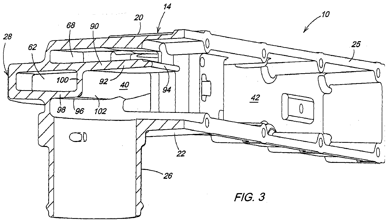
- a pair of EGR control valve assemblies 34, 36 are inserted through side 20 and into manifold 10. As best seen in Fig. 3, the housing 14 forms an intake chamber 40 and an outlet plenum 42. Intake air flows from intake 26 through chamber 40 to plenum 42.
- housing 14 forms an EGR inlet chamber 50 which extends between walls 90, 96.
- the EGR inlet chamber 50 is preferably formed at a location equidistant from the fore-and-aft ends of the manifold 10.
- Housing 14 also forms a pair of EGR valve chambers 56, 58 which extend between sides 20, 22.
- a first EGR inlet passage 60 communicates EGR from EGR inlet chamber 50 to a central portion of valve chamber 56.
- a second EGR inlet passage 62 communicates EGR from EGR inlet chamber 50 to a central portion of valve chamber 58.
- the EGR valve chambers 56 and 58 are parallel to and spaced equidistant from a fore-and-aft extending centerline or longitudinal axis of the engine 12.
- housing 14 forms a first EGR outlet chamber 64 adjacent to valve chamber 56 and a second EGR outlet chamber 66 adjacent to valve chamber 58.
- a central EGR outlet passage 68 communicates the upper portion of valve chambers 56, 58 to plenum 42.
- a first upper EGR outlet passage 70 communicates an upper portion of valve chamber 56 to an upper portion of EGR outlet chamber 64.
- a first lower EGR outlet passage 72 communicates a lower portion of valve chamber 56 to a lower portion of EGR outlet chamber 64.
- a second upper EGR outlet passage 74 communicates an upper portion of valve chamber 58 to an upper portion of EGR outlet chamber 66.
- a second lower EGR outlet passage 76 communicates a lower portion of valve chamber 58 to a lower portion of EGR outlet chamber 66.
- Ports 80, 82, 84, 85 and 86 communicate EGR to the outlet plenum 42.
- housing 14 forms a wall 90 which separates passage 68 from passage 62 and from intake chamber 40.
- Wall 90 includes an inner portion or shelf 92 which projects substantially normal to the central axis of intake 26 to an edge 94 at which passage 68 and intake chamber 40 merge into outlet plenum 42.
- a wall 96 separates passage 62 from intake chamber 40.
- Wall 96 includes a generally horizontal wall 98 and a generally vertical wall 100 joined at a corner 102. The wall 96, corner 102 and shelf 92 create turbulence in the air intake stream which helps evenly and quickly mix the intake air with the EGR from passage 68.
- a bore 104 is machined through side 20 and walls 96 and 90 to receive EGR valve 34 in valve chamber 56.
- a bore 106 is machined through side 20 and walls 96 and 90 to receive EGR valve 36 in valve chamber 58.
- a bore 108 is machined through side 20 to provide an opening to which EGR supply conduit 30 is connected.
- the bores 104, 106 and 108 could be machined through side 22 so that the manifold 10 can be flipped over and oriented as shown in Fig. 8 and have the air intake 26 projecting upwardly, while EGR valves 34, 36 and the EGR supply conduit 30 are still connected to the upper surface (now side 22) of the manifold 10.
- the result is a single intake cover casting which has several specially tuned EGR distribution ports that mixes the EGR and intake air well. No venturis are needed to achieve EGR introduction and mixing. EGR and air are mixed quickly in a compact structure.
- the EGR supply tube and EGR valve mountings are aligned with the engine centerline and can be machined on either side of the manifold. Tooling costs are reduced by providing one casting which can be mounted in different orientations.
Abstract
The invention refers to an intake manifold (10) for mixing and
supplying air and exhaust gas recirculation (EGR) to an
internal combustion engine (12), comprising:
Description
The present invention relates to an intake manifold which
mixes recirculated exhaust gas (EGR) with the fresh air for a
diesel engine.
There is a need for a diesel engine which meets Tier 3
emission regulations. To effectively meet the emissions
requirements with minimal impact of fuel economy and engine
durability, the EGR and fresh air must be evenly mixed and
evenly distributed among the cylinders. Previously, EGR and
fresh intake air has been mixed with apparatus which includes
venturi type inlets, or mixing devices which require
additional parts and controls.
To reduce costs, it would also be desirable to have an engine
EGR system which permits EGR flow rate to be determined by
measuring a temperature differential and without sensing a
pressure differential across a flow element such as a venture
and without using a flow meter. This requires even EGR/fresh
air mixing. But, it very difficult to mix EGR and air evenly
and quickly because EGR and fresh air have significantly
different densities.
It would also be desirable to have an EGR/fresh air mixing
intake manifold which can be placed in different orientations
so that the fresh air intake can be oriented upwardly or
downwardly.
An object of the invention is to provide such an intake
manifold in which EGR and fresh air are evenly mixed and
evenly distributed among the cylinders. The EGR flow rate be
determinable by measuring a temperature differential. A
further object of the invention is to provide such an intake
manifold which can be placed in different orientations so that
the fresh air intake can be oriented upwardly or downwardly.
These and other objects are achieved by the present invention,
wherein an intake manifold mixes EGR and air and supplies the
mixed air and exhaust gas to an internal combustion engine.
The manifold is a casting which forms a housing which is
attached to a side of an engine. The housing has an EGR inlet
and an outlet plenum. A fresh air intake projects from one
side of the manifold. A pair of EGR inlet passages communicate
EGR from the EGR inlet to respective ones of a pair of spaced
apart EGR valve chambers in which EGR valves are mounted. A
pair of EGR outlet chambers communicate from the valve
chambers to outlet ports which communicate with the plenum. A
central EGR outlet passage communicates EGR to a central part
of the plenum. Bores or openings may be formed or machined
into either side of the manifold for receiving EGR valves and
for connecting to an EGR supply conduit. Thus, the manifold
may be oriented with the intake opening upwardly or downwardly
and with the EGR valves and the EGR supply conduit always
attached to the upper surface thereof.
An embodiment of the invention is shown in the drawings, in
which:
Referring to Figs. 1, 2 and 3, an intake manifold 10 is
mounted on the side of an engine 12. The manifold 10 supplies
air and recirculated exhaust gas (EGR) to the engine 12 having
combustion chambers (not shown). The manifold 10 is preferably
a casting.
The manifold 10 has an outer housing 14 which has fore and aft
ends 16, 18 extending in fore and aft directions, spaced apart
first and second outer walls 20, 22 on opposite sides of the
manifold 10, both extending generally horizontally, an outer
wall 24 joining the first and second sides to each other and
an inner surface 25 which sealingly engages the engine 12.
Housing 14 forms an air intake 26 which projects away from
side 22. A temperature sensor port 27 is formed in intake 26
for receiving a conventional temperature sensor 31 for sensing
the temperature of intake air therein. Housing 14 forms an EGR
inlet subhousing 28 which projects away from the engine side
of the manifold 10. An EGR conduit 30 communicates EGR from
EGR cooler 32 to the subhousing 28. A temperature sensor port
29 is formed in subhousing 28 for receiving a conventional
temperature sensor 33 for sensing the temperature of the EGR
therein. A pair of EGR control valve assemblies 34, 36 are
inserted through side 20 and into manifold 10. As best seen in
Fig. 3, the housing 14 forms an intake chamber 40 and an
outlet plenum 42. Intake air flows from intake 26 through
chamber 40 to plenum 42.
As best seen in Figs. 5 and 7, housing 14 forms an EGR inlet
chamber 50 which extends between walls 90, 96. The EGR inlet
chamber 50 is preferably formed at a location equidistant from
the fore-and-aft ends of the manifold 10. Housing 14 also
forms a pair of EGR valve chambers 56, 58 which extend between
sides 20, 22. A first EGR inlet passage 60 communicates EGR
from EGR inlet chamber 50 to a central portion of valve
chamber 56. A second EGR inlet passage 62 communicates EGR
from EGR inlet chamber 50 to a central portion of valve
chamber 58. Preferably, the EGR valve chambers 56 and 58 are
parallel to and spaced equidistant from a fore-and-aft
extending centerline or longitudinal axis of the engine 12.
Referring now to Figs. 4, 6 and 7, housing 14 forms a first
EGR outlet chamber 64 adjacent to valve chamber 56 and a
second EGR outlet chamber 66 adjacent to valve chamber 58. A
central EGR outlet passage 68 communicates the upper portion
of valve chambers 56, 58 to plenum 42. A first upper EGR
outlet passage 70 communicates an upper portion of valve
chamber 56 to an upper portion of EGR outlet chamber 64. A
first lower EGR outlet passage 72 communicates a lower portion
of valve chamber 56 to a lower portion of EGR outlet chamber
64. A second upper EGR outlet passage 74 communicates an upper
portion of valve chamber 58 to an upper portion of EGR outlet
chamber 66. A second lower EGR outlet passage 76 communicates
a lower portion of valve chamber 58 to a lower portion of EGR
outlet chamber 66. Ports 80, 82, 84, 85 and 86 communicate EGR
to the outlet plenum 42.
As best seen in Figs. 3 and 7, housing 14 forms a wall 90
which separates passage 68 from passage 62 and from intake
chamber 40. Wall 90 includes an inner portion or shelf 92
which projects substantially normal to the central axis of
intake 26 to an edge 94 at which passage 68 and intake chamber
40 merge into outlet plenum 42. A wall 96 separates passage 62
from intake chamber 40. Wall 96 includes a generally
horizontal wall 98 and a generally vertical wall 100 joined at
a corner 102. The wall 96, corner 102 and shelf 92 create
turbulence in the air intake stream which helps evenly and
quickly mix the intake air with the EGR from passage 68. A
bore 104 is machined through side 20 and walls 96 and 90 to
receive EGR valve 34 in valve chamber 56. A bore 106 is
machined through side 20 and walls 96 and 90 to receive EGR
valve 36 in valve chamber 58. A bore 108 is machined through
side 20 to provide an opening to which EGR supply conduit 30
is connected.
Alternatively, the bores 104, 106 and 108 could be machined
through side 22 so that the manifold 10 can be flipped over
and oriented as shown in Fig. 8 and have the air intake 26
projecting upwardly, while EGR valves 34, 36 and the EGR
supply conduit 30 are still connected to the upper surface
(now side 22) of the manifold 10.
The result is a single intake cover casting which has several
specially tuned EGR distribution ports that mixes the EGR and
intake air well. No venturis are needed to achieve EGR
introduction and mixing. EGR and air are mixed quickly in a
compact structure. The EGR supply tube and EGR valve mountings
are aligned with the engine centerline and can be machined on
either side of the manifold. Tooling costs are reduced by
providing one casting which can be mounted in different
orientations.
Claims (3)
- An intake manifold (10) for mixing and supplying air and exhaust gas recirculation (EGR) to an internal combustion engine (12), the manifold (10) comprising:a housing (14) for attaching to a side of an engine, the housing (14) having a first outer wall (20) forming one side of the manifold (10) and having a second outer wall (22) spaced apart from the first outer wall (20) and forming an opposite side of the manifold (10);an air intake port (26) projecting from the first outer wall (22);an EGR valve chamber (56, 58) extending between the first and second outer walls (20, 22), a selected one of the first and second walls (20, 22) having a valve opening formed therein;an EGR valve assembly (34, 36) inserted through the valve opening and into the valve chamber (56, 58) through said selected wall (20,22); andan EGR inlet chamber (50) extending between the first and second walls (20, 22), said selected wall (20, 22) having an EGR supply opening formed therein; andan EGR supply conduit (30) connected to the inlet chamber (50) through the supply opening in the selected wall (20, 22), the EGR valve assembly (34, 36) and the EGR supply conduit (30) thereby being mountable on a wall (20, 22) which is the same as or opposite to the first wall (22, 20) from which projects the intake port (26).
- The intake manifold according to claim 1, wherein:the EGR inlet chamber (50) is located equidistant from fore-and-aft ends of the manifold (10).
- The intake manifold according to claim 1 or 2, wherein the manifold (10) comprises:a pair of spaced apart EGR valve chambers (56, 58), each extending between the first and second outer walls (20, 22), a selected one of the first and second walls (20, 22) having a corresponding pair of valve opening formed therein; anda pair of EGR valve assemblies (34, 36), each valve assembly (34, 36) being inserted through a corresponding one of the valve openings and into the corresponding valve chamber (56, 58) through said selected wall (20, 22), the EGR valve chambers (56, 58) being spaced equidistant from a fore-and-aft extending centerline of the manifold (10).
Applications Claiming Priority (4)
| Application Number | Priority Date | Filing Date | Title |
|---|---|---|---|
| US801752 | 1997-02-18 | ||
| US10/801,752 US6945237B1 (en) | 2004-03-15 | 2004-03-15 | Intake manifold with EGR/air mixing |
| US802976 | 2004-03-17 | ||
| US10/802,976 US6935321B1 (en) | 2004-03-17 | 2004-03-17 | EGR/air mixing intake manifold with dual orientations |
Publications (1)
| Publication Number | Publication Date |
|---|---|
| EP1577537A2 true EP1577537A2 (en) | 2005-09-21 |
Family
ID=34841283
Family Applications (1)
| Application Number | Title | Priority Date | Filing Date |
|---|---|---|---|
| EP05101633A Withdrawn EP1577537A2 (en) | 2004-03-15 | 2005-03-03 | Intake manifold for mixing and supplying air and exhaust gas recirculation |
Country Status (1)
| Country | Link |
|---|---|
| EP (1) | EP1577537A2 (en) |
-
2005
- 2005-03-03 EP EP05101633A patent/EP1577537A2/en not_active Withdrawn
Similar Documents
| Publication | Publication Date | Title |
|---|---|---|
| EP1577536A2 (en) | Intake manifold for supplying air and exhaust recirculation gas to an internal combustion engine | |
| US6935321B1 (en) | EGR/air mixing intake manifold with dual orientations | |
| US4805564A (en) | Engine intake manifold assembly | |
| JP2004245148A (en) | Positive crankcase ventilation system blow-by gas reflux fitment for internal-combustion engine | |
| US10612499B2 (en) | Air intake apparatus | |
| EP3043061A1 (en) | Intake system for internal combustion engine | |
| JPS62294757A (en) | Self-sufficiency exhaust recirculating system for insertion between cylinder head and suction manifold for internal combustion engine | |
| JP3210825B2 (en) | V-type multi-cylinder engine intake system | |
| US5014654A (en) | Intake manifold for internal combustion engine | |
| US20200240374A1 (en) | Engine device | |
| US20210231045A1 (en) | Engine Device | |
| US9611810B2 (en) | Gaseous fuel mixer with exhaust gas recirculation | |
| JP2010150927A (en) | Exhaust gas recirculating device for internal combustion engine | |
| JP2003074430A (en) | Intake device for multicylinder engine | |
| US20060075997A1 (en) | Intake manifold for an internal combustion engine | |
| US11193460B2 (en) | Multi-cylinder engine intake structure | |
| JP2003262164A (en) | Air intake device for internal combustion engine | |
| CN107178445B (en) | Gas reflux device | |
| WO2016120049A1 (en) | Gaseous fuel mixer | |
| EP1577537A2 (en) | Intake manifold for mixing and supplying air and exhaust gas recirculation | |
| JP3699226B2 (en) | Catamaran vaporizer | |
| JP4398607B2 (en) | Mixer for multi-cylinder gas engine | |
| JPH0232857Y2 (en) | ||
| JPH0517416Y2 (en) | ||
| US7665449B2 (en) | V-type engine |
Legal Events
| Date | Code | Title | Description |
|---|---|---|---|
| PUAI | Public reference made under article 153(3) epc to a published international application that has entered the european phase |
Free format text: ORIGINAL CODE: 0009012 |
|
| AK | Designated contracting states |
Kind code of ref document: A2 Designated state(s): AT BE BG CH CY CZ DE DK EE ES FI FR GB GR HU IE IS IT LI LT LU MC NL PL PT RO SE SI SK TR |
|
| AX | Request for extension of the european patent |
Extension state: AL BA HR LV MK YU |
|
| STAA | Information on the status of an ep patent application or granted ep patent |
Free format text: STATUS: THE APPLICATION HAS BEEN WITHDRAWN |
|
| 18W | Application withdrawn |
Effective date: 20091121 |