EP1577432A2 - Rotating-drum machine for dyeing textile articles - Google Patents
Rotating-drum machine for dyeing textile articles Download PDFInfo
- Publication number
- EP1577432A2 EP1577432A2 EP04077374A EP04077374A EP1577432A2 EP 1577432 A2 EP1577432 A2 EP 1577432A2 EP 04077374 A EP04077374 A EP 04077374A EP 04077374 A EP04077374 A EP 04077374A EP 1577432 A2 EP1577432 A2 EP 1577432A2
- Authority
- EP
- European Patent Office
- Prior art keywords
- drum
- fluid
- treatment
- tank
- articles
- Prior art date
- Legal status (The legal status is an assumption and is not a legal conclusion. Google has not performed a legal analysis and makes no representation as to the accuracy of the status listed.)
- Withdrawn
Links
Images

Classifications
-
- D—TEXTILES; PAPER
- D06—TREATMENT OF TEXTILES OR THE LIKE; LAUNDERING; FLEXIBLE MATERIALS NOT OTHERWISE PROVIDED FOR
- D06B—TREATING TEXTILE MATERIALS USING LIQUIDS, GASES OR VAPOURS
- D06B5/00—Forcing liquids, gases or vapours through textile materials to effect treatment, e.g. washing, dyeing, bleaching, sizing impregnating
- D06B5/12—Forcing liquids, gases or vapours through textile materials to effect treatment, e.g. washing, dyeing, bleaching, sizing impregnating through materials of definite length
- D06B5/26—Forcing liquids, gases or vapours through textile materials to effect treatment, e.g. washing, dyeing, bleaching, sizing impregnating through materials of definite length using centrifugal force
-
- D—TEXTILES; PAPER
- D06—TREATMENT OF TEXTILES OR THE LIKE; LAUNDERING; FLEXIBLE MATERIALS NOT OTHERWISE PROVIDED FOR
- D06B—TREATING TEXTILE MATERIALS USING LIQUIDS, GASES OR VAPOURS
- D06B1/00—Applying liquids, gases or vapours onto textile materials to effect treatment, e.g. washing, dyeing, bleaching, sizing or impregnating
- D06B1/02—Applying liquids, gases or vapours onto textile materials to effect treatment, e.g. washing, dyeing, bleaching, sizing or impregnating by spraying or projecting
-
- D—TEXTILES; PAPER
- D06—TREATMENT OF TEXTILES OR THE LIKE; LAUNDERING; FLEXIBLE MATERIALS NOT OTHERWISE PROVIDED FOR
- D06B—TREATING TEXTILE MATERIALS USING LIQUIDS, GASES OR VAPOURS
- D06B3/00—Passing of textile materials through liquids, gases or vapours to effect treatment, e.g. washing, dyeing, bleaching, sizing, impregnating
- D06B3/30—Passing of textile materials through liquids, gases or vapours to effect treatment, e.g. washing, dyeing, bleaching, sizing, impregnating of articles, e.g. stockings
Definitions
- the invention concerns a rotating-drum machine for dyeing textile articles.
- the machine in question is intended to be used advantageously in the industrial sector in order to treat with dyeing processes textile articles or garments of any kind made from a wide range of fabrics.
- the machines for treating textile articles conventionally consist of a frame resting on the ground and supporting a containing tank inside which a treatment fluid usually consisting of water containing, mixed therewith or in solution form, various dyeing products is introduced.
- the tank has, arranged inside it, a drum which can be operated so as to rotate by special movement means in accordance with operating steps predefined by the programmed treatment cycles.
- the drum is equipped with a loading hatch for receiving the textile articles to undergo the dyeing treatment and with a plurality of through-holes through which the treatment fluid flows.
- the latter is stored inside a bath provided at the bottom of the tank.
- the dyeing treatment conventionally occurs during rotation of the drum, as a result of the continuous immersion and extraction of the articles within/from the bath. Colouring of the articles occurs in fact as a result of the mechanical action due to falling of the articles inside the rotating drum which allows uniform penetration of the treatment fluid into the fibres. This action may be assisted by the presence of vanes which are fixed to the drum and which raise the textile articles above the treatment bath and then release them when they reach the top of the drum so that they fall as a result of gravity into the said treatment bath.
- a first drawback consists in the use of large amounts of water which is the direct result of operation using machines with high bath ratios. This in fact constitutes a problem in those countries where water is a precious commodity which must be conserved and used with great care.
- the fluid is removed from the bottom of the tank and conveyed to an external circuit in order to be temperature-regulated by suitable heating means so that the bath reaches the temperature envisaged by the various programmed treatment cycles.
- the dosage of numerous products required for the treatment of the garments is directly or indirectly proportional to the quantity of fluid used for the bath.
- the quantity of fluid required by the machines known hitherto is necessarily dependent upon the quantity of fluid which forms the bath contained in the bottom of the tank.
- the problem underlying the present invention is that of overcoming the drawbacks of the art known hitherto by providing a rotating-drum machine for dyeing textile articles, which is able to achieve a reduction in the bath ratio without adversely affecting the quality of the treatment carried out on the said articles.
- a further object of the present invention is to provide a machine which allows operation with a particularly low bath ratio while ensuring a correct removal of the fluid from the bath by circulating means provided.
- a further object of the present invention is to provide a machine which does not require the use of a treatment bath in which the articles are immersed in order to perform dyeing thereof.
- a further object of the present invention is to provide a machine equipped with treatment means which are able to operate with any type of article and in particular with delicate articles while nevertheless maintaining a high quality of treatment without damaging the said articles.
- a further object of the present invention to provide a machine equipped with a rotating drum able to avoid creating turbulence inside a storage bath provided.
- a further object of the present invention is to provide a machine which is operationally entirely reliable.
- 1 denotes in its entirety the rotating-drum dyeing machine forming the subject of the present invention.
- Said machine is intended to be used for the treatment of textile articles M of any type and made of any material and in particular for carrying out dyeing treatments thereon.
- the machine 1 is composed of a support frame 2 which rests on the ground and which supports a containing tank 3 via rigid or resiliently yielding support means 4 which are conventional per se.
- the tank 3 has a substantially cylindrical shape and contains inside it with play 5 a rotating drum 6 which is also substantially cylindrical and has a side wall 7 which extends longitudinally along the axis Y between two end walls, i.e. a front end wall 8 and rear end wall 9, both of which are substantially disc-shaped.
- the front wall 8 is equipped with a hatch 40 for loading the rotating drum 6 with the textile articles M to be treated.
- a transmission shaft 10 supported by means of bearings is fixed to the rear wall 9 of the rotating drum 6 and is actuated in a controlled manner and in accordance with predefined operating steps by suitable motorized means 100 which are known per se and for this reason are not shown in detail.
- the rotating drum 6 is preferably made of steel and it is possible to envisage fixing inside it several radial blades which are able to divide its internal volume into segments, said blades also being of a type known per se, but not envisaged in the preferred examples of embodiment shown in the accompanying figures.
- the side surface 7 is provided with a plurality of holes 11 able to allow a treatment fluid to flow between the tank 3 and the inside of the drum 6.
- the invention envisages the use of treatment means 50 able to keep the bath ratios at very low values.
- These means 50 comprise nozzle means 51 which are composed of one or more nozzles, mounted on the tank, on one or both the end walls 8, 9 of the drum 6, and which emit a jet of fluid 60 inside the drum 6 which extends along the longitudinal length of the latter so as to reach the articles M distributed along the side wall 7.
- nozzle means 51 advantageously comprising a single nozzle 18 which is located on the front wall 8 (examples in Figures 1 and 2) or the rear wall 9 (example in Figure 3), it being understood, however, that these nozzle means 51 may also envisage the use of several nozzles located on the front wall 8 or also only on the rear wall 9 with the respective jets being able to be combined, on top of each other or alongside each other, without departing from the protective scope of the present invention.
- the nozzle 18 is arranged in a substantially axial position, mounted on the loading hatch 40 of the tank 3 arranged facing the front wall 8 of the drum 6.
- the nozzle 18 is mounted on the distribution shaft 10 which is axially hollow so as to allow to pass through it the end part 17" of the line 17 described in greater detail below.
- the jet of fluid 60 has a laminar form and emerges from the nozzle or from the plurality of nozzles provided, at a pressure of between 0.5 and 5 atmospheres.
- the laminar form of the jet 60 extends in accordance with the example shown in the accompanying figures along the whole longitudinal length of the drum 6. As it leaves the nozzle 18, the jet 60 widens slightly and preferably assumes a form which, viewed in cross-section, is substantially triangular with the base of the jet 60 arranged in the region of the articles M and having a width preferably of between 5 and 30 cm.
- This form of the jet 60 is preferred and the choice thereof takes into account the flow rate and the pressure of the treatment fluid as well as the bath ratio and the methods of treating the articles M.
- the nozzle 18 is mounted on the loading hatch 40 so as not to extend, except by a small amount, inside the containing chamber defined by the drum 6 so as to avoid interfering with the textile articles during rotation of the said drum 6.
- Protection means 70 consisting for example of a nozzle-covering housing fixed to the wall of the tank above the nozzle 18, may be envisaged.
- the jet 60 is preferably directed towards the bottom part of the drum 6 (see Figures 1 and 2) so that the nozzle 18 may be more easily protected, at the top, from falling garments M by the protection means 70, but may also be directed towards the top as indicated in the example shown in Figure 3.
- the nozzle 18 never substantially interferes with the movement of the garments M arranged inside the drum 6, and its jet spraying function, which may be in both an atomized and non-atomized form, always remains fully effective in operational terms.
- the garments are made to adhere to the inner side surface of the drum, as a result of the action of the drum speed which is sufficient for the garments to overcome the force of gravity.
- the protection means 70 prove to be useful, in particular when, in order to change the distribution of the garments inside the drum, pauses or reversals in the direction of rotation of the drum are envisaged, causing the garments to become detached and fall from its inner side surface.
- the treatment means also comprise a storage bath 12 contained inside a reservoir 13 which is connected by means of a circulating system 14 to the nozzles 18 and to the tank 3 and is arranged in a position remote from the rotating drum 6 so that the bath 12 is not affected by the turbulence following rotation of the rotating drum 6.
- the circulating system draws the treatment liquid from the bottom of the tank so as to prevent the garments from being immersed inside a pool on the bottom thereof and introduces it into the drum by means of the nozzles which distribute it in an appropriate manner.
- the invention substantially eliminates the treatment bath inside the tank 3, which is usually used to perform dyeing treatments, and instead makes use of a storage bath 12 arranged in a position at a distance from the drum 6, which position, depending on the specific constructional solution may be chosen, for example outside the tank 3, as in the examples according to Figures 1 and 3, or inside a portion of the tank 3, as in the example according to Figure 2.
- the circulating system 14 comprises a connecting line 15 connected, at its first end 15', to the top of the reservoir 13 and, at its second end 15", to a lower collecting portion 16 of the tank 3 for removing the fluid from the latter and introducing it inside the reservoir 13 so as to supply the bath 12 in accordance with predefined operating steps.
- the said fluid circulating system 14 also comprises a supply line 17 connected in turn at a first end 17' to the bottom of the reservoir 13 and at a second end 17" to the nozzle 18 for drawing the fluid from the bath 12 and introducing it under pressure inside the rotating drum 6.
- the line 17 has, arranged along it, a recirculating pump 19 able to cause the fluid to flow around the circulating system 14.
- the reservoir 13 is formed in a bottom portion 20 of the tank 3 and into it flows all the fluid which has acted on the garments M during treatment and accumulates as a result of gravity.
- the fluid circulating system 14 comprises in this case, using the same numbers as in the preceding example, a supply line 17 connected at a first end 17' to the bottom of the reservoir 13 and at the second end 17" to the nozzle 18 so as to draw the fluid from the bath 12 and introduce it under pressure inside the rotating drum 6.
- the line 17 has, arranged along it, a recirculating pump 19 able to cause the fluid to flow around the circulating system 14.
- heating means are also provided, said means acting on the storage bath 12 so as to heat it to the temperature envisaged by the various treatment cycles.
- heating means advantageously consist of an electric resistance indicated by means of a coil 21 in the accompanying figures.
- the said heating means may be of the steam heating type or consist of other systems which are well-known to a person skilled in the art.
- the treatment fluid usually consists partly of water and partly of products which are mixed or in solution form inside it.
- Supply means 23 are also envisaged for introducing the products into the reservoir 13.
- the said supply means comprise a container body or mixer 24 for mixing treatment products P which are introduced inside it manually or automatically, removing them from special basins connected to the container body 24, and a line 5 which has, arranged along it, a pump 26 and is connected to the container body 24 and to the reservoir 13 for replenishing the bath 12 with the products P necessary for carrying out the various programmed treatment cycles.
- the treatment fluid may assume the desired characteristics such as, for example, a given pH value, a given temperature, or a given composition, by regulating automatically using a logic control unit or also manually the storage bath 12 contained inside the reservoir 13 with the introduction of specific products or with the aid of the heating means 21.
- the treatment means 50 also comprise a source 80 of pressurised gaseous fluid, preferably air or nitrogen, connected to the nozzle 18 (or nozzles) by means of a line 81 having, arranged along it, manual or automatic regulating means 82.
- a source 80 of pressurised gaseous fluid preferably air or nitrogen
- the jet emitted from the nozzle 18 will preferably consist of a combination of the treatment fluid in the liquid state and the gaseous fluid in the gaseous state.
- This latter fluid is able to perform the dual function of supporting the treatment fluid so as to allow it to reach even the farthest positions of the side wall 7 of the drum 6 as well as limit the impact of the jet 60 of treatment fluid on the garments M in particular when the latter are of a delicate nature.
- the treatment fluid and gaseous fluid it is possible to reduce the density of the jet 60 acting on the garments M or the number of droplets of fluid which reach, per unit of area or per unit of time, the garments M to be treated.
- a step involving removal of the fluid from the bottom of the tank is also envisaged, so that there is no accumulated liquid with which the articles must interfere during their rotation.
- an accumulation of liquid on the bottom of the tank would also cause an accumulation on the bottom of the drum 6.
- This situation would mean that the articles which rotate adhering to the drum 6 would interact violently with this accumulated liquid, impairing their perfect condition.
- the more delicate articles would thus be damaged, namely their surface would have long threads forming the so-called napped effect.
- dyeing is performed by means of treatment cycles which envisage rotational movements of the drum 6, during which the textile articles M are made to adhere to the side surface of the drum 6 by the centrifugal force imparted to them by the rotation of the drum 6.
- the laminar jet of fluid 60 can be distributed over the entire longitudinal length of the drum 6, reaching the garments distributed inside it and suitably treating them without being interrupted by the falling garments.
- the articles are made to adhere by the centrifugal force on the internal surface of the drum with the correct compression able to avoid subjecting the articles on the surface to wear, in particular avoiding the formation of zones exposed to varying degrees of treatment opposite the holes in the drum and the smooth parts.
- the same centrifugal force is able to impart to the articles a sufficient degree of softness and looseness or, on the other hand, optimum compaction in order to allow correct penetration of the cleaning or dyeing liquid.
- rotation of the drum is correlated to the pressure of the fluid jet so as to allow correct penetration, depending on the type of garment treated, of the dyeing fluid into the fibre of the textile articles.
- this centrifugal acceleration is designed to ensure an optimum speed of penetration of the liquid also depending on the type of fabric to be treated.
- the dyeing method according to the present invention allows dyeing of the textile articles without mechanical action and keeping them immobile on the side wall of the drum with a suitable compressive force.
- the present invention goes against the common knowledge of the sector which instead envisaged a mechanical beating action in order to allow uniform distribution of the dye within the fibres.
Abstract
Description
- The invention concerns a rotating-drum machine for dyeing textile articles.
- The machine in question is intended to be used advantageously in the industrial sector in order to treat with dyeing processes textile articles or garments of any kind made from a wide range of fabrics.
- At present, in accordance with the known art, the machines for treating textile articles conventionally consist of a frame resting on the ground and supporting a containing tank inside which a treatment fluid usually consisting of water containing, mixed therewith or in solution form, various dyeing products is introduced.
- The tank has, arranged inside it, a drum which can be operated so as to rotate by special movement means in accordance with operating steps predefined by the programmed treatment cycles. The drum is equipped with a loading hatch for receiving the textile articles to undergo the dyeing treatment and with a plurality of through-holes through which the treatment fluid flows.
- The latter is stored inside a bath provided at the bottom of the tank.
- From an operational point of view the dyeing treatment conventionally occurs during rotation of the drum, as a result of the continuous immersion and extraction of the articles within/from the bath. Colouring of the articles occurs in fact as a result of the mechanical action due to falling of the articles inside the rotating drum which allows uniform penetration of the treatment fluid into the fibres. This action may be assisted by the presence of vanes which are fixed to the drum and which raise the textile articles above the treatment bath and then release them when they reach the top of the drum so that they fall as a result of gravity into the said treatment bath.
- In order to achieve effective treatment of the articles, these machines of the known type mentioned above must operate with an adequate bath volume or with "bath ratios" - understood as meaning the ratio between the weight of the textile articles and the weight of the treatment bath - which are fairly high and in the region of between 1:10 to 1:30.
- These high bath ratios involve a series of drawbacks which ultimately result in somewhat high machine management costs.
- In greater detail, a first drawback consists in the use of large amounts of water which is the direct result of operation using machines with high bath ratios. This in fact constitutes a problem in those countries where water is a precious commodity which must be conserved and used with great care.
- A second drawback is associated with the high consumption of energy necessary for heating baths formed by large quantities of treatment fluid. Obviously this fact has a negative impact on the operating costs of the machine and ultimately on the costs of the processes for treatment of the garments as a whole.
- Normally, the fluid is removed from the bottom of the tank and conveyed to an external circuit in order to be temperature-regulated by suitable heating means so that the bath reaches the temperature envisaged by the various programmed treatment cycles.
- It must also be considered that the dosage of numerous products required for the treatment of the garments, such as for example dyes, acid salts, etc. is directly or indirectly proportional to the quantity of fluid used for the bath.
- Therefore it is obvious that the greater the quantity of fluid which forms a bath the greater will also be the costs for maintaining inside it the desired concentrations of products for treatment of the garments.
- It is known in particular that the treatment products which are introduced mainly in measured amounts depending on the quantity by weight (in kilograms) of textile articles to be treated, instead of the volume of the bath, nevertheless also have a greater effect if they are used in a concentrated manner or if they are not excessively diluted in large-volume baths.
- All of this clearly reveals the need in the sector in question - hitherto unfulfilled - to reduce the bath ratios with the aim of bringing down the costs associated with the use of large quantities of treatment products, large quantities of water and high consumption of thermal energy, however produced, for heating the bath.
- More recently, so-called high-speed machines have been developed, said machines by means of innovative dyeing techniques in which the articles remain in contact with the rotating drum allowing the use of bath ratios with values which are advantageously even as low as declared values of 1:5 and in any case lower those obtained in the more conventional machines mentioned above.
- In the case of these latter machines also it is necessary to use a treatment bath contained at the bottom of the tank, which partially projects inside the drum up to a predefined height so as to allow the immersion and the extraction of the articles.
- Therefore, the quantity of fluid required by the machines known hitherto is necessarily dependent upon the quantity of fluid which forms the bath contained in the bottom of the tank.
- It must also be considered that, particularly in these high-speed machines, it may be required to remove by means of suitable circulating means a quantity of fluid from the bottom of the tank.
- In fact, in the presence of high flow rates and/or in the presence of small-volume baths, turbulence occurs within the said baths on the bottom of the tank, due to the rotation of the drum, which hinders correct draw-off of the fluid and does not ensure a constant flow rate within the circulating means nor a constant head upstream of the pump of the circulating means.
- In this context, the problem underlying the present invention is that of overcoming the drawbacks of the art known hitherto by providing a rotating-drum machine for dyeing textile articles, which is able to achieve a reduction in the bath ratio without adversely affecting the quality of the treatment carried out on the said articles.
- A further object of the present invention is to provide a machine which allows operation with a particularly low bath ratio while ensuring a correct removal of the fluid from the bath by circulating means provided.
- A further object of the present invention is to provide a machine which does not require the use of a treatment bath in which the articles are immersed in order to perform dyeing thereof.
- A further object of the present invention is to provide a machine equipped with treatment means which are able to operate with any type of article and in particular with delicate articles while nevertheless maintaining a high quality of treatment without damaging the said articles.
- A further object of the present invention to provide a machine equipped with a rotating drum able to avoid creating turbulence inside a storage bath provided.
- A further object of the present invention is to provide a machine which is operationally entirely reliable.
- These and other objects are all achieved by a machine according to the accompanying claims.
- The technical features of the invention, in accordance with abovementioned objects, may be clearly determined from the contents of the claims provided below and the advantages thereof will emerge more clearly from the detailed description which follows, with reference to the accompanying drawings which show two purely exemplary and non-limiting examples of embodiment thereof in which:
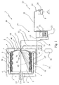
- Figure 1 shows an overall partially cross-sectioned view of a first embodiment of the machine according to the invention;
- Figure 2 shows an overall partially cross-sectioned view of a second example of embodiment of the machine according to the invention;
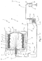
- Figure 3 shows an overall partially cross-sectioned view of a third example of embodiment of the machine according to the invention.
- In accordance with the figures of the accompanying drawings, 1 denotes in its entirety the rotating-drum dyeing machine forming the subject of the present invention.
- Said machine is intended to be used for the treatment of textile articles M of any type and made of any material and in particular for carrying out dyeing treatments thereon.
- From a structural point of view, the
machine 1 is composed of asupport frame 2 which rests on the ground and which supports a containingtank 3 via rigid or resiliently yielding support means 4 which are conventional per se. - The
tank 3 has a substantially cylindrical shape and contains inside it with play 5 arotating drum 6 which is also substantially cylindrical and has aside wall 7 which extends longitudinally along the axis Y between two end walls, i.e. afront end wall 8 andrear end wall 9, both of which are substantially disc-shaped. - The
front wall 8 is equipped with ahatch 40 for loading the rotatingdrum 6 with the textile articles M to be treated. - A
transmission shaft 10 supported by means of bearings is fixed to therear wall 9 of the rotatingdrum 6 and is actuated in a controlled manner and in accordance with predefined operating steps by suitable motorized means 100 which are known per se and for this reason are not shown in detail. - The rotating
drum 6 is preferably made of steel and it is possible to envisage fixing inside it several radial blades which are able to divide its internal volume into segments, said blades also being of a type known per se, but not envisaged in the preferred examples of embodiment shown in the accompanying figures. - The
side surface 7 is provided with a plurality ofholes 11 able to allow a treatment fluid to flow between thetank 3 and the inside of thedrum 6. - The invention envisages the use of treatment means 50 able to keep the bath ratios at very low values. These means 50 comprise nozzle means 51 which are composed of one or more nozzles, mounted on the tank, on one or both the
end walls drum 6, and which emit a jet offluid 60 inside thedrum 6 which extends along the longitudinal length of the latter so as to reach the articles M distributed along theside wall 7. - Below reference will be made to the example which envisages the presence of nozzle means 51 advantageously comprising a
single nozzle 18 which is located on the front wall 8 (examples in Figures 1 and 2) or the rear wall 9 (example in Figure 3), it being understood, however, that these nozzle means 51 may also envisage the use of several nozzles located on thefront wall 8 or also only on therear wall 9 with the respective jets being able to be combined, on top of each other or alongside each other, without departing from the protective scope of the present invention. - In particular, with reference to the examples shown in Figures 1 and 2, advantageously the
nozzle 18 is arranged in a substantially axial position, mounted on theloading hatch 40 of thetank 3 arranged facing thefront wall 8 of thedrum 6. - With reference to the example shown in Figure 3, the
nozzle 18 is mounted on thedistribution shaft 10 which is axially hollow so as to allow to pass through it theend part 17" of theline 17 described in greater detail below. - In greater detail, in accordance with a preferred embodiment of the present invention, the jet of
fluid 60 has a laminar form and emerges from the nozzle or from the plurality of nozzles provided, at a pressure of between 0.5 and 5 atmospheres. The laminar form of thejet 60 extends in accordance with the example shown in the accompanying figures along the whole longitudinal length of thedrum 6. As it leaves thenozzle 18, thejet 60 widens slightly and preferably assumes a form which, viewed in cross-section, is substantially triangular with the base of thejet 60 arranged in the region of the articles M and having a width preferably of between 5 and 30 cm. This form of thejet 60 is preferred and the choice thereof takes into account the flow rate and the pressure of the treatment fluid as well as the bath ratio and the methods of treating the articles M. A person skilled in the art, in order to satisfy contingent and specific requirements, may make numerous modifications and adaptations to the preferred form of thejet 60 described above. - Advantageously the
nozzle 18 is mounted on theloading hatch 40 so as not to extend, except by a small amount, inside the containing chamber defined by thedrum 6 so as to avoid interfering with the textile articles during rotation of the saiddrum 6. - Protection means 70, consisting for example of a nozzle-covering housing fixed to the wall of the tank above the
nozzle 18, may be envisaged. - The
jet 60 is preferably directed towards the bottom part of the drum 6 (see Figures 1 and 2) so that thenozzle 18 may be more easily protected, at the top, from falling garments M by the protection means 70, but may also be directed towards the top as indicated in the example shown in Figure 3. - In accordance with the above description, the
nozzle 18 never substantially interferes with the movement of the garments M arranged inside thedrum 6, and its jet spraying function, which may be in both an atomized and non-atomized form, always remains fully effective in operational terms. - Preferably, as will be clarified below, during the dyeing treatment, the garments are made to adhere to the inner side surface of the drum, as a result of the action of the drum speed which is sufficient for the garments to overcome the force of gravity. In this case, the protection means 70 prove to be useful, in particular when, in order to change the distribution of the garments inside the drum, pauses or reversals in the direction of rotation of the drum are envisaged, causing the garments to become detached and fall from its inner side surface.
- According to a further characteristic feature of the present invention, the treatment means also comprise a
storage bath 12 contained inside areservoir 13 which is connected by means of a circulatingsystem 14 to thenozzles 18 and to thetank 3 and is arranged in a position remote from the rotatingdrum 6 so that thebath 12 is not affected by the turbulence following rotation of the rotatingdrum 6. - Owing to the possibility of having a
storage bath 12 which is not affected by the rotation of thedrum 6, it is possible to draw from the said bath 12 a constant and large flow of fluid able to be used to supply thenozzle 18 with flow volumes and pressures suitable for treating the articles M effectively and at the same time keep the bath ratios within extremely low values, for example values of about 1:2. This means that, for each kilogram of fabric to be dyed or washed, only two kilograms of fluid are used. - In practice, the circulating system draws the treatment liquid from the bottom of the tank so as to prevent the garments from being immersed inside a pool on the bottom thereof and introduces it into the drum by means of the nozzles which distribute it in an appropriate manner.
- In this way, the invention substantially eliminates the treatment bath inside the
tank 3, which is usually used to perform dyeing treatments, and instead makes use of astorage bath 12 arranged in a position at a distance from thedrum 6, which position, depending on the specific constructional solution may be chosen, for example outside thetank 3, as in the examples according to Figures 1 and 3, or inside a portion of thetank 3, as in the example according to Figure 2. - In greater detail, according to the examples in Figures 1 and 3, the circulating
system 14 comprises a connectingline 15 connected, at its first end 15', to the top of thereservoir 13 and, at itssecond end 15", to alower collecting portion 16 of thetank 3 for removing the fluid from the latter and introducing it inside thereservoir 13 so as to supply thebath 12 in accordance with predefined operating steps. - The said
fluid circulating system 14 also comprises asupply line 17 connected in turn at a first end 17' to the bottom of thereservoir 13 and at asecond end 17" to thenozzle 18 for drawing the fluid from thebath 12 and introducing it under pressure inside therotating drum 6. - The
line 17 has, arranged along it, arecirculating pump 19 able to cause the fluid to flow around the circulatingsystem 14. - In accordance with the example of embodiment shown in Figure 2, the
reservoir 13 is formed in abottom portion 20 of thetank 3 and into it flows all the fluid which has acted on the garments M during treatment and accumulates as a result of gravity. - The
fluid circulating system 14 comprises in this case, using the same numbers as in the preceding example, asupply line 17 connected at a first end 17' to the bottom of thereservoir 13 and at thesecond end 17" to thenozzle 18 so as to draw the fluid from thebath 12 and introduce it under pressure inside therotating drum 6. - In this case also, the
line 17 has, arranged along it, arecirculating pump 19 able to cause the fluid to flow around the circulatingsystem 14. - In both the examples of embodiment described heating means are also provided, said means acting on the
storage bath 12 so as to heat it to the temperature envisaged by the various treatment cycles. - These means advantageously consist of an electric resistance indicated by means of a
coil 21 in the accompanying figures. Obviously, without departing as a result from the scope of protection of the present invention, the said heating means may be of the steam heating type or consist of other systems which are well-known to a person skilled in the art. - The treatment fluid usually consists partly of water and partly of products which are mixed or in solution form inside it.
- Supply means 23 are also envisaged for introducing the products into the
reservoir 13. - In greater detail, the said supply means comprise a container body or
mixer 24 for mixing treatment products P which are introduced inside it manually or automatically, removing them from special basins connected to thecontainer body 24, and aline 5 which has, arranged along it, apump 26 and is connected to thecontainer body 24 and to thereservoir 13 for replenishing thebath 12 with the products P necessary for carrying out the various programmed treatment cycles. - Therefore, at any time during the cycle for treating the garments M, the treatment fluid may assume the desired characteristics such as, for example, a given pH value, a given temperature, or a given composition, by regulating automatically using a logic control unit or also manually the
storage bath 12 contained inside thereservoir 13 with the introduction of specific products or with the aid of the heating means 21. - The use of one or
more spraying nozzles 18 in particular with pressurised jets supplied by a controlled flow drawn from the bath 12 (not influenced by the movement of the drum 6) allows a considerable reduction in the bath ratio down to values as low as 1:2 or less. - Advantageously, in accordance with a preferred embodiment of the present invention, in all the examples considered, the treatment means 50 also comprise a
source 80 of pressurised gaseous fluid, preferably air or nitrogen, connected to the nozzle 18 (or nozzles) by means of aline 81 having, arranged along it, manual or automatic regulating means 82. - The jet emitted from the
nozzle 18 will preferably consist of a combination of the treatment fluid in the liquid state and the gaseous fluid in the gaseous state. This latter fluid is able to perform the dual function of supporting the treatment fluid so as to allow it to reach even the farthest positions of theside wall 7 of thedrum 6 as well as limit the impact of thejet 60 of treatment fluid on the garments M in particular when the latter are of a delicate nature. In fact, by means of the abovementioned combination of the treatment fluid and gaseous fluid it is possible to reduce the density of thejet 60 acting on the garments M or the number of droplets of fluid which reach, per unit of area or per unit of time, the garments M to be treated. - Owing to this measure it is possible to carry out the delicate treatment in particular of those articles which are composed of fibres which otherwise would be easily damaged by an excessively strong jet.
- Moreover, owing to the provision of a
reservoir 13 outside themachine 1, it is possible to remove easily the treatment fluid in order to carry out dyeing tests on small quantities of fabric in small-size apparatus. - As a result of the invention it is therefore possible to reduce the use of products, water and energy with a notable saving in cost terms, while ensuring an optimum treatment of the garments.
- Preferably dyeing of the articles is performed using the machine described hitherto and acting in accordance with the method claimed which comprises the following operating steps:
- a step involving introduction of the textile articles M
inside the chamber containing the
drum 6 via the loading hatch; - a step involving distribution of the textile articles M
on the side wall of the
drum 6 by means of rotation of the latter at a speed sufficient to keep the said articles M adhering to the side wall; - a step involving dyeing of the textile articles M by
means of introduction, inside the
drum 6, of a laminar jet of fluid extending preferably along the whole longitudinal length of the saiddrum 6 so as to reach the garments adhering to the side wall. This dyeing step envisages the penetration of the fluid into the fibres of the articles when they are kept in contact with the side wall of thedrum 6 by the centrifugal force exerted on them by rotation of the saiddrum 6. - A step involving removal of the fluid from the bottom of the tank is also envisaged, so that there is no accumulated liquid with which the articles must interfere during their rotation. In fact, since the
drum 6 is perforated, an accumulation of liquid on the bottom of the tank would also cause an accumulation on the bottom of thedrum 6. This situation would mean that the articles which rotate adhering to thedrum 6 would interact violently with this accumulated liquid, impairing their perfect condition. Especially the more delicate articles would thus be damaged, namely their surface would have long threads forming the so-called napped effect. - Therefore in accordance with the method of the present invention, dyeing is performed by means of treatment cycles which envisage rotational movements of the
drum 6, during which the textile articles M are made to adhere to the side surface of thedrum 6 by the centrifugal force imparted to them by the rotation of thedrum 6. In this way, the laminar jet offluid 60 can be distributed over the entire longitudinal length of thedrum 6, reaching the garments distributed inside it and suitably treating them without being interrupted by the falling garments. In order to change the distribution of the garments M on the surface of thedrum 6, it is envisaged between the treatment cycles, introducing pauses or changing in the speed of the drum or reversing the direction of rotation of the drum so as to force the garments M to be released and hence be redistributed over the surface of the said drum. The articles are made to adhere by the centrifugal force on the internal surface of the drum with the correct compression able to avoid subjecting the articles on the surface to wear, in particular avoiding the formation of zones exposed to varying degrees of treatment opposite the holes in the drum and the smooth parts. The same centrifugal force is able to impart to the articles a sufficient degree of softness and looseness or, on the other hand, optimum compaction in order to allow correct penetration of the cleaning or dyeing liquid. - For this purpose, rotation of the drum is correlated to the pressure of the fluid jet so as to allow correct penetration, depending on the type of garment treated, of the dyeing fluid into the fibre of the textile articles.
- Therefore this centrifugal acceleration is designed to ensure an optimum speed of penetration of the liquid also depending on the type of fabric to be treated.
- Surprisingly, the dyeing method according to the present invention allows dyeing of the textile articles without mechanical action and keeping them immobile on the side wall of the drum with a suitable compressive force. In this respect, the present invention goes against the common knowledge of the sector which instead envisaged a mechanical beating action in order to allow uniform distribution of the dye within the fibres.
- A person skilled in the art, in order to satisfy contingent and specific requirements, may apply to the preferred embodiment of the rotating-drum machine described above substantial modifications, adaptations and replacements of parts with others which are functionally equivalent, without however departing from the scope of the following claims.
Claims (22)
- Rotating-drum machine for dyeing textile articles, comprising:characterized in that said treatment means comprise at least one nozzle which is operationally provided on at least one wall of said drum chosen from said rear wall and said front wall and able to produce a jet of fluid inside said drum extending along the longitudinal length of the said drum so as to reach the garments distributed over the side wall.a support frame;a tank supported by said frame;a rotating drum contained inside said tank and defining a chamber for containing textile articles, delimited by at least one rear wall, by at least one front wall provided with a loading hatch for inserting textile articles and by at least one side wall having, formed therein, a plurality of through-holes for allowing the passage of a treatment fluid between said rotating drum and said tank;treatment means for acting on said articles with said treatment fluid;
- Machine according to Claim 1, characterized in that said treatment means comprise a reservoir for containing a storage bath, arranged in a position remote from said rotating drum, and a circulating system connected to said tank and to said reservoir for supplying said at least one nozzle with a treatment liquid supplied from said bath, said circulating system being able to draw said treatment liquid from said tank, preventing the garments from being immersed inside a pool of liquid on the bottom thereof, said storage bath not being substantially affected by the turbulence due to rotation of said drum.
- Machine according to any one of the preceding claims, characterized in that said textile articles are treated by means of said treatment means while they are made to adhere to the side surface of said drum by the centrifugal force imparted to them by the speed of rotation of said drum during treatment thereof.
- Rotating-drum dyeing machine for treating textile articles, comprising:characterized in that said treatment means comprise:a support frame;a tank supported by said frame;a rotating drum rotated by driving means and contained inside said tank, defining a chamber for containing textile articles delimited by at least one rear wall, by at least one front wall provided with a loading hatch for inserting textile articles and by at least one side wall having, formed therein, a plurality of through-holes for allowing the passage of a treatment fluid between said rotating drum and said tank;treatment means for acting on said articles with said treatment fluid;said machine being characterized moreover in that said driving means cause rotation of said drum at a speed at least sufficient for the centrifugal force to keep said textile articles adhering to the side surface of said drum and in that said jet of fluid interferes with said textile articles adhering to the wall, penetrating inside their fibres.at least one nozzle which is operationally provided on at least one wall of said drum chosen from said rear wall and said front wall and able to produce a jet of fluid inside said drum extending along the longitudinal length of the said drum so as to reach the garments distributed over the side wall;a reservoir for containing a storage bath, arranged in a position remote from said rotating drum; anda circulating system connected to said tank and to said reservoir for supplying said at least one nozzle with a treatment liquid supplied from said bath, said circulating system being able to draw said treatment liquid from said tank, preventing the garments from being immersed inside a pool of liquid on the bottom thereof, and said storage bath not being substantially affected by the turbulence due to rotation of said drum;
- Machine according to Claim 1 or 4, characterized in that said treatment means comprise a source of pressurised gaseous fluid connected to said at least one nozzle so as to introduce a jet composed of a treatment fluid in the liquid state and a fluid in the gaseous state.
- Machine according to any one of the preceding claims, characterized in that the jet of said treatment fluid is pressurised and has a laminar form.
- Machine according to any one of the preceding claims, characterized in that said jet of treatment fluid is at a pressure of between 0.5 and 5 atmospheres measured at the outlet of said at least one nozzle.
- Machine according to any one of the preceding claims, characterized in that said at least one nozzle does not protrude substantially inside the containing chamber defined by said drum and does not interfere substantially with said textile articles during rotation of said drum.
- Machine according to any one of the preceding claims, characterized in that said at least one nozzle is arranged in a substantially axial position.
- Machine according to any one of the preceding claims, characterized in that said at least one nozzle is mounted on said loading hatch.
- Machine according to any one of the preceding claims, characterized in that it comprises protection means envisaged for partially covering said nozzle so as to prevent said textile articles from interfering with said nozzle.
- Machine according to any one of the preceding claims, characterized in that said jet is formed by a combination of several jets produced by several nozzles.
- Machine according to any one of the preceding claims, characterized in that said jet is directed towards the bottom of the drum.
- Machine according to Claim 2 or 4, characterized in that said circulating system comprises:at least one connecting line connected to said reservoir and to said tank for drawing the fluid from said tank and introducing it inside said reservoir;at least one supply line connected to said reservoir and to said bath for drawing the fluid from said bath and introducing it inside said rotating drum;at least one recirculating pump for causing the fluid to flow around said circulating system.
- Machine according to Claim 2, characterized in that said reservoir is formed in a portion of said tank into which said treatment fluid flows.
- Machine according to Claim 15, characterized in that said circulating system comprises:at least one supply line connected to said reservoir and to said tank for drawing the fluid from said bath and introducing it inside said rotating drum;at least one recirculating pump for causing the fluid to flow around said circulating system.
- Machine according to any one of the preceding claims, characterized in that it comprises heating means acting on said storage bath.
- Machine according to any one of the preceding claims, characterized in that it comprises means for supplying treatment products, comprising:a container body for mixing treatment products;at least one line connected to said container body and to said reservoir for supplying said bath with said treatment products.
- Method for dyeing textile articles, comprising the following operating steps:a step involving introduction of said textile articles inside a drum contained inside a tank and having at least one side wall with a plurality of through-holes for allowing a treatment fluid to pass between said drum and said tank;a step involving distribution of said articles on the side wall of the drum by means of rotation of the drum at a speed sufficient to keep the articles adhering to the side wall;a step involving dyeing said textile articles by means of introduction, inside the drum, of a jet of fluid extending along the longitudinal length of the said drum so as to reach the garments adhering to the side wall; said dyeing step envisaging the penetration of said fluid into the fibre of said articles when said articles are kept in contact with the walls of said drum as a result of the centrifugal force due to its rotation;a step involving removal of said fluid introduced into said drum so that there is no accumulated liquid on the bottom of the tank, with which the articles interfere during rotation thereof;
- Dyeing method according to Claim 19, comprising a step involving redistribution of said articles on the side surface of said drum by means of variation or stoppage of the speed of the drum, able to allow separation of the articles from the side wall of the drum and reorganization thereof during a subsequent distribution step.
- Dyeing method according to Claim 19, characterized in that the introduction, inside the drum, of said jet of fluid is performed with a pressurised laminar jet.
- Dyeing method according to Claim 19, characterized in that the rotation of the drum is correlated to the pressure of the jet of fluid so as to allow penetration of the dyeing fluid completely inside the fibre of the textile articles.
Applications Claiming Priority (4)
| Application Number | Priority Date | Filing Date | Title |
|---|---|---|---|
| ITPD20040035 | 2004-02-11 | ||
| ITPD20040035 ITPD20040035A1 (en) | 2004-02-11 | 2004-02-11 | MACHINE WITH ROTATING BASKET TO TREAT TEXTILE OBJECTS |
| ITPD20040034 | 2004-02-11 | ||
| ITPD20040034 ITPD20040034A1 (en) | 2004-02-11 | 2004-02-11 | MACHINE WITH ROTATING BASKET TO TREAT TEXTILE OBJECTS |
Publications (2)
| Publication Number | Publication Date |
|---|---|
| EP1577432A2 true EP1577432A2 (en) | 2005-09-21 |
| EP1577432A3 EP1577432A3 (en) | 2006-10-11 |
Family
ID=34839952
Family Applications (1)
| Application Number | Title | Priority Date | Filing Date |
|---|---|---|---|
| EP04077374A Withdrawn EP1577432A3 (en) | 2004-02-11 | 2004-08-23 | Rotating-drum machine for dyeing textile articles |
Country Status (1)
| Country | Link |
|---|---|
| EP (1) | EP1577432A3 (en) |
Cited By (5)
| Publication number | Priority date | Publication date | Assignee | Title |
|---|---|---|---|---|
| IT201900019436A1 (en) * | 2019-10-21 | 2021-04-21 | Tonello Srl | EQUIPMENT FOR BLEACHING OR TREATMENT OF ARTICLES, SUCH AS, FOR EXAMPLE, CLOTHING |
| WO2022039986A1 (en) * | 2020-08-19 | 2022-02-24 | Novastar Solutions Inc. | Systems and methods for automated post processing of 3d printed objects |
| IT202100007826A1 (en) * | 2021-03-30 | 2022-09-30 | Make In Italy Srl | CLOSED CIRCUIT DYEING MACHINE FOR GARMENTS AND RELATED METHOD. |
| CN115161926A (en) * | 2022-05-09 | 2022-10-11 | 马鞍山市丝诺达针织品有限公司 | Dyeing apparatus is used in panty hose production |
| CN116219664A (en) * | 2023-05-08 | 2023-06-06 | 广东弘益纺织有限公司 | Centrifugal flow-blocking opposite-impact mixed printing and dyeing device and application thereof in knitted fabric preparation |
Citations (1)
| Publication number | Priority date | Publication date | Assignee | Title |
|---|---|---|---|---|
| JPH09783A (en) * | 1995-04-21 | 1997-01-07 | Sharp Corp | Washing machine |
Family Cites Families (2)
| Publication number | Priority date | Publication date | Assignee | Title |
|---|---|---|---|---|
| US2966052A (en) * | 1955-11-17 | 1960-12-27 | Whirlpool Co | Laundry machine and method |
| US5187955A (en) * | 1991-09-20 | 1993-02-23 | G. A. Braun, Inc. | Center shaft dye injection apparatus |
-
2004
- 2004-08-23 EP EP04077374A patent/EP1577432A3/en not_active Withdrawn
Patent Citations (1)
| Publication number | Priority date | Publication date | Assignee | Title |
|---|---|---|---|---|
| JPH09783A (en) * | 1995-04-21 | 1997-01-07 | Sharp Corp | Washing machine |
Cited By (9)
| Publication number | Priority date | Publication date | Assignee | Title |
|---|---|---|---|---|
| IT201900019436A1 (en) * | 2019-10-21 | 2021-04-21 | Tonello Srl | EQUIPMENT FOR BLEACHING OR TREATMENT OF ARTICLES, SUCH AS, FOR EXAMPLE, CLOTHING |
| EP3812497A1 (en) * | 2019-10-21 | 2021-04-28 | Tonello S.r.l. | Apparatus for decoloring or treating manufactured articles, such as for example items of clothing |
| CN112760868A (en) * | 2019-10-21 | 2021-05-07 | 托内洛有限责任公司 | Device for bleaching or treating an industrial article, such as an article of clothing |
| WO2022039986A1 (en) * | 2020-08-19 | 2022-02-24 | Novastar Solutions Inc. | Systems and methods for automated post processing of 3d printed objects |
| IT202100007826A1 (en) * | 2021-03-30 | 2022-09-30 | Make In Italy Srl | CLOSED CIRCUIT DYEING MACHINE FOR GARMENTS AND RELATED METHOD. |
| CN115161926A (en) * | 2022-05-09 | 2022-10-11 | 马鞍山市丝诺达针织品有限公司 | Dyeing apparatus is used in panty hose production |
| CN115161926B (en) * | 2022-05-09 | 2023-09-08 | 马鞍山市丝诺达针织品有限公司 | Dyeing apparatus is used in production of panty-hose |
| CN116219664A (en) * | 2023-05-08 | 2023-06-06 | 广东弘益纺织有限公司 | Centrifugal flow-blocking opposite-impact mixed printing and dyeing device and application thereof in knitted fabric preparation |
| CN116219664B (en) * | 2023-05-08 | 2023-06-27 | 广东弘益纺织有限公司 | Centrifugal flow-blocking opposite-impact mixed printing and dyeing device and application thereof in knitted fabric preparation |
Also Published As
| Publication number | Publication date |
|---|---|
| EP1577432A3 (en) | 2006-10-11 |
Similar Documents
| Publication | Publication Date | Title |
|---|---|---|
| CA2182287C (en) | Mist treatment of garments | |
| US4432111A (en) | Procedure for washing clothes | |
| US5621937A (en) | Jet dyeing apparatus and method | |
| KR101604648B1 (en) | Apparatus and process for the treatment of strand-shaped textile products | |
| EP2061923B1 (en) | Washing machine | |
| US7578152B2 (en) | Wet processing or finishing machine for rope-formed textile products | |
| EP2628844A1 (en) | Laundry treatment apparatus with heat exchanger cleaning | |
| KR20180027412A (en) | METHOD OF TREATING FIBER SUBSTRATE AND APPARATUS | |
| EP1577432A2 (en) | Rotating-drum machine for dyeing textile articles | |
| US5440771A (en) | Jet dyeing apparatus and method | |
| US5129242A (en) | Low-liquid jet machine for wet processing textile fabric | |
| KR101672361B1 (en) | method of making assembled clothes | |
| EP1218583B1 (en) | Continuous fabric rinsing method and apparatus | |
| US5299339A (en) | Jet dyeing apparatus and method | |
| WO2002004733A1 (en) | Business-use laundering method and business-use laundering device using the method | |
| EP1865097A1 (en) | Machine and method for treating fabric | |
| JPH0673658A (en) | Pneumatic treatment device of rope-like soft goods and treating method therefor | |
| EP2550388B1 (en) | Machine for the discontinuous treatment of fabric ropes | |
| US5210896A (en) | Center shaft dye injection process | |
| US5187955A (en) | Center shaft dye injection apparatus | |
| KR100986144B1 (en) | Dyeing machine | |
| GB1587069A (en) | Wet processing machines | |
| JP3747540B2 (en) | Textile product liquid processing apparatus and textile product manufacturing method | |
| KR940008392Y1 (en) | Dyeing machine | |
| DE123187C (en) |
Legal Events
| Date | Code | Title | Description |
|---|---|---|---|
| PUAI | Public reference made under article 153(3) epc to a published international application that has entered the european phase |
Free format text: ORIGINAL CODE: 0009012 |
|
| AK | Designated contracting states |
Kind code of ref document: A2 Designated state(s): AT BE BG CH CY CZ DE DK EE ES FI FR GB GR HU IE IT LI LU MC NL PL PT RO SE SI SK TR |
|
| AX | Request for extension of the european patent |
Extension state: AL HR LT LV MK |
|
| PUAL | Search report despatched |
Free format text: ORIGINAL CODE: 0009013 |
|
| AK | Designated contracting states |
Kind code of ref document: A3 Designated state(s): AT BE BG CH CY CZ DE DK EE ES FI FR GB GR HU IE IT LI LU MC NL PL PT RO SE SI SK TR |
|
| AX | Request for extension of the european patent |
Extension state: AL HR LT LV MK |
|
| 17P | Request for examination filed |
Effective date: 20070403 |
|
| TPAC | Observations filed by third parties |
Free format text: ORIGINAL CODE: EPIDOSNTIPA |
|
| AKX | Designation fees paid |
Designated state(s): ES IT TR |
|
| REG | Reference to a national code |
Ref country code: DE Ref legal event code: 8566 |
|
| 17Q | First examination report despatched |
Effective date: 20110325 |
|
| STAA | Information on the status of an ep patent application or granted ep patent |
Free format text: STATUS: THE APPLICATION IS DEEMED TO BE WITHDRAWN |
|
| 18D | Application deemed to be withdrawn |
Effective date: 20111006 |