EP1577229A2 - Improvements of the hydrophobic properties of the tilting valve grommet of an aerosol can - Google Patents
Improvements of the hydrophobic properties of the tilting valve grommet of an aerosol can Download PDFInfo
- Publication number
- EP1577229A2 EP1577229A2 EP05075623A EP05075623A EP1577229A2 EP 1577229 A2 EP1577229 A2 EP 1577229A2 EP 05075623 A EP05075623 A EP 05075623A EP 05075623 A EP05075623 A EP 05075623A EP 1577229 A2 EP1577229 A2 EP 1577229A2
- Authority
- EP
- European Patent Office
- Prior art keywords
- grommet
- rubber
- aerosol
- aerosol valve
- composition
- Prior art date
- Legal status (The legal status is an assumption and is not a legal conclusion. Google has not performed a legal analysis and makes no representation as to the accuracy of the status listed.)
- Withdrawn
Links
Images
Classifications
-
- B—PERFORMING OPERATIONS; TRANSPORTING
- B65—CONVEYING; PACKING; STORING; HANDLING THIN OR FILAMENTARY MATERIAL
- B65D—CONTAINERS FOR STORAGE OR TRANSPORT OF ARTICLES OR MATERIALS, e.g. BAGS, BARRELS, BOTTLES, BOXES, CANS, CARTONS, CRATES, DRUMS, JARS, TANKS, HOPPERS, FORWARDING CONTAINERS; ACCESSORIES, CLOSURES, OR FITTINGS THEREFOR; PACKAGING ELEMENTS; PACKAGES
- B65D83/00—Containers or packages with special means for dispensing contents
- B65D83/14—Containers or packages with special means for dispensing contents for delivery of liquid or semi-liquid contents by internal gaseous pressure, i.e. aerosol containers comprising propellant for a product delivered by a propellant
- B65D83/44—Valves specially adapted therefor; Regulating devices
- B65D83/46—Tilt valves
-
- B—PERFORMING OPERATIONS; TRANSPORTING
- B65—CONVEYING; PACKING; STORING; HANDLING THIN OR FILAMENTARY MATERIAL
- B65D—CONTAINERS FOR STORAGE OR TRANSPORT OF ARTICLES OR MATERIALS, e.g. BAGS, BARRELS, BOTTLES, BOXES, CANS, CARTONS, CRATES, DRUMS, JARS, TANKS, HOPPERS, FORWARDING CONTAINERS; ACCESSORIES, CLOSURES, OR FITTINGS THEREFOR; PACKAGING ELEMENTS; PACKAGES
- B65D83/00—Containers or packages with special means for dispensing contents
- B65D83/14—Containers or packages with special means for dispensing contents for delivery of liquid or semi-liquid contents by internal gaseous pressure, i.e. aerosol containers comprising propellant for a product delivered by a propellant
- B65D83/38—Details of the container body
Definitions
- the present invention concerns an improvement to a rubber grommet for a tilting and/or gun aerosol valve grommet (hereafter called the aerosol valve grommet), more particularly regarding the protection against moisture diffusion and uptake through the rubber grommet.
- the aerosol valve will be used for dispensing one or two component polyurethane (PU) foam systems contained in a pressurized can or vessel or any other polymer system curing or sensitive by/to moisture/water uptake.
- PU polyurethane
- the type of aerosol valves relevant for the present invention is used for more than 25 years in order to dispense the content of an aerosol can.
- the valve By tilting or vertical activation of the stem, the valve opens and delivers the vessel's content.
- Such a valve consists of a number of plastic and metal parts.
- the inner gasket/seal, called the grommet, is made of rubber.
- Other parts are a special metal cup with inlaid rubber gasket and a plastic stem.
- the polyurethane and/or similar components formed due to moisture uptake (diffusion) inside the can or vessel sticks against the grommet and or the stem. Once the first layer of PU formed on the grommet on the face inside the can or vessel, the sealing properties of the valve diminished and makes the valve subject to blocking and/or leaking.
- a standard tilting or gun valve get stucked after contact with the polyurethane prepolymer in the can at higher temperature and higher conditions of humidity. This contact is made possible by inappropriate storage of cans (horizontal or upside down) or excessive shaking during transport.
- a hydrophobic thermoplastic or non thermoplastic elastomer could be used such as : styrene-butadiene, butylene-styrene, silicone rubbers, isopropyl ether (Kraton, Shell), chlorinated polyethylene (Tyrin, Dupont de Nemours), epichlorhydrin homopolymers or copolymer, ethylene propylene (Nordel, Dupont de Nemours), fluoroelastomers (Viton, Dupont de Nemours), alcryn MPR (chlorinated olefin interpolymer alloy), Santoprene etc.
- a rubber grommet with a moisture barrier provided by chemical treatment of a rubber grommet that may be otherwise usual.
- the rubber can be BUNA, EPDM or Neoprene, butyl etc...
- the chemical treatment is a coating of at least part of the grommet surface in contact with the container's component, by a inert hydrophobic substance dispensed or brushed on said surface or by dipping or impregnation of the whole grommet into the substance.
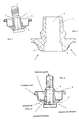
- Fig. 1 illustrates an example of the tilting of a valve as is well-known, with the grommet 1, the stem 4 and the cup 5 to be coupled with the aerosol can or vessel (not illustrated).
- the tilting action provides an open passageway for the content of the can.
- Fig. 2 illustrates a similar valve, the arrows indicating the diffusion of the propellant and prepolymer from the inside of the can on one side and, on the other side, of the moisture from the environment. It is to be noted that the moisture may access the grommet also through the hollow stem. There is shown an internal “front” in the grommet where a reaction between both components occurs and wherein consequently hardness is increased.
- Fig. 3 represents schematically a transversal section of an isolated classical grommet 1 with a hole 2 for the stem and for which the bottom part 3 has been coated according to the invention, for example by spraying (arrows), brushing, dipping or impregnation of the whole grommet.
- the chemicals used for this type of application are preferably silicon or fluoro-polymer based compositions.
- the treatment may be conducted either by spraying or directly laying a coating by dipping or impregnation of the whole grommet.
- a coating/reactive agent preferably just after demoulding the rubber, it can be sprayed by a coating/reactive agent.
- the rubber can also be brushed, impregnated or plasma treated in order to obtain a coating on the whole surface of the grommet or only on the bottom part (ref. 3 in fig. 1).
- the applied composition can be a solution of fluoro-polymer or a silicon based composition.
- ACMOS 70-2406 ACMOS 70-2406
- the Münch coating spray MKX 02-125 may also be used. It is postulated that some chemical (covalent) bonding is produced between the coating and the rubber.
- the grommet is siliconized. This extra post siliconisation improves the snappiness of the rubber and the multi-use properties of the valve.
- a typical silicone mixture used is Bayer M350.
Abstract
The present invention concerns an improvement to a rubber
grommet for a tilting and/or gun aerosol valve grommet,
more particularly regarding the protection against moisture
diffusion and uptake through the rubber grommet. The
grommet has at least one part of its surface treated by a
hydrophobic composition. It may be a non-thermoplastic
rubber-type grommet. The coating composition is polymeric.
The grommet may be siliconized after the treatment. The
treatment comprises the step of spraying, impregnating,
brushing or laying by plasma treatment a coating of a
silicon or fluoro-polymer based composition on at least
part of its surface.
Description
The present invention concerns an improvement to a rubber
grommet for a tilting and/or gun aerosol valve grommet
(hereafter called the aerosol valve grommet), more
particularly regarding the protection against moisture
diffusion and uptake through the rubber grommet.
Generally the aerosol valve will be used for dispensing one
or two component polyurethane (PU) foam systems contained
in a pressurized can or vessel or any other polymer system
curing or sensitive by/to moisture/water uptake.
The type of aerosol valves relevant for the present
invention is used for more than 25 years in order to
dispense the content of an aerosol can. By tilting or
vertical activation of the stem, the valve opens and
delivers the vessel's content. Such a valve consists of a
number of plastic and metal parts. The inner gasket/seal,
called the grommet, is made of rubber. Other parts are a
special metal cup with inlaid rubber gasket and a plastic
stem.
Since the chemical components present in the can or vessel
are water sensitive and react with water to form for
example the final polyurea in the case of a polyurethane
prepolymer , it should be acknowledged that any contact
with ambient moisture is to be avoided in order to prevent
the forming of polyurethane and/or similar derivatives
inside the can or vessel. Moisture penetrates via the
valve system, more particularly through the grommet in the
case of aerosol valves.
The polyurethane and/or similar components formed due to
moisture uptake (diffusion) inside the can or vessel sticks
against the grommet and or the stem. Once the first layer
of PU formed on the grommet on the face inside the can or
vessel, the sealing properties of the valve diminished and
makes the valve subject to blocking and/or leaking.
A standard tilting or gun valve get stucked after contact
with the polyurethane prepolymer in the can at higher
temperature and higher conditions of humidity. This
contact is made possible by inappropriate storage of cans
(horizontal or upside down) or excessive shaking during
transport.
It is believed that the stucking/blocking of the valve is
made possible by a combination of at least two features
- water diffusion through the grommet from the outside to the inside of the aerosol can or vessel,
- diffusion of prepolymer through the grommet from the inside of the can with the propellant as carrier.
Where both water and prepolymer are meeting a reaction will
take place and a kind of cylindrical hardness front will be
formed. This hardness front will prevent the stem from
being tilted or displace vertically and will result in a
stucked valve.
Therefore there is a need for an improved appropriate
moisture repulsive grommet.
In order to prevent moisture uptake through the grommet, a
hydrophobic thermoplastic or non thermoplastic elastomer
could be used such as : styrene-butadiene,
butylene-styrene, silicone rubbers, isopropyl ether
(Kraton, Shell), chlorinated polyethylene (Tyrin, Dupont de
Nemours), epichlorhydrin homopolymers or copolymer,
ethylene propylene (Nordel, Dupont de Nemours),
fluoroelastomers (Viton, Dupont de Nemours), alcryn MPR
(chlorinated olefin interpolymer alloy), Santoprene etc..
According to the present invention, there is a provided a
rubber grommet with a moisture barrier provided by chemical
treatment of a rubber grommet that may be otherwise usual.
The rubber can be BUNA, EPDM or Neoprene, butyl etc...
The chemical treatment is a coating of at least part of the
grommet surface in contact with the container's component,
by a inert hydrophobic substance dispensed or brushed on
said surface or by dipping or impregnation of the whole
grommet into the substance.
The invention will be better understood with reference to
the annexed figures provided as examples.
Fig. 1 illustrates an example of the tilting of a valve as
is well-known, with the grommet 1, the stem 4 and the cup 5
to be coupled with the aerosol can or vessel (not
illustrated). The tilting action provides an open
passageway for the content of the can.
Fig. 2 illustrates a similar valve, the arrows indicating
the diffusion of the propellant and prepolymer from the
inside of the can on one side and, on the other side, of
the moisture from the environment. It is to be noted that
the moisture may access the grommet also through the hollow
stem. There is shown an internal "front" in the grommet
where a reaction between both components occurs and wherein
consequently hardness is increased.
Fig. 3 represents schematically a transversal section of an
isolated classical grommet 1 with a hole 2 for the stem and
for which the bottom part 3 has been coated according to
the invention, for example by spraying (arrows), brushing,
dipping or impregnation of the whole grommet.
The chemicals used for this type of application are
preferably silicon or fluoro-polymer based compositions.
According to the invention, the treatment may be conducted
either by spraying or directly laying a coating by dipping
or impregnation of the whole grommet. For example,
preferably just after demoulding the rubber, it can be
sprayed by a coating/reactive agent. The rubber can also
be brushed, impregnated or plasma treated in order to
obtain a coating on the whole surface of the grommet or
only on the bottom part (ref. 3 in fig. 1). The applied
composition can be a solution of fluoro-polymer or a
silicon based composition.
It has been found that a silicon based composition for
coating or impregnation of the ACMOS type is appropriate,
for example ACMOS 70-2406. The Münch coating spray MKX
02-125 may also be used. It is postulated that some
chemical (covalent) bonding is produced between the coating
and the rubber.
After the coating, impregnation or plasma treatment, the
grommet is siliconized. This extra post siliconisation
improves the snappiness of the rubber and the multi-use
properties of the valve. A typical silicone mixture used
is Bayer M350.
A significant improvement in overall properties of the
valve is noticed. In a test, the aerosols or vessels are
stored vertically, horizontally and shaken every day, which
represent critical situations for a valve. It has however
been found that the valves treated according to the
invention are still working and no leakage or blocking of
the can or vessel is encountered.
Claims (9)
- An aerosol valve comprising a grommet having at least one part of its surface treated by a hydrophobic composition.
- An aerosol valve according to claim 1 wherein the grommet is a non-thermoplastic rubber-type grommet.
- An aerosol valve comprising a rubber-type grommet having at least one part of its surface coated by a polymeric hydrophobic chemical composition.
- An aerosol valve comprising a rubber-type grommet having at least one part of its surface coated by a polymeric hydrophobic chemical and where the hydrophobic properties of the valves are obtainable by a combination of both the gas permeation properties of the grommet compound and the hydrophobic properties of the coating.
- An aerosol valve according to any of the claims 1 to 3 wherein the composition is a silicon or fluoro-polymer based composition.
- An aerosol valve according to any of the preceding claims wherein the grommet is treated on its bottom surface, oriented inside the container.
- An aerosol valve according to any previous claims wherein the grommet is siliconized after the treatment.
- A container comprising a valve according to any of the previous claims.
- A method for treating a grommet of a valve comprising the step of spraying, impregnating, brushing or laying by plasma treatment a coating of a silicon or fluoro-polymer based composition on at least part of its surface.
Priority Applications (1)
| Application Number | Priority Date | Filing Date | Title |
|---|---|---|---|
| EP05075623A EP1577229A2 (en) | 2004-03-15 | 2005-03-15 | Improvements of the hydrophobic properties of the tilting valve grommet of an aerosol can |
Applications Claiming Priority (3)
| Application Number | Priority Date | Filing Date | Title |
|---|---|---|---|
| EP04075878 | 2004-03-15 | ||
| EP04075878 | 2004-03-15 | ||
| EP05075623A EP1577229A2 (en) | 2004-03-15 | 2005-03-15 | Improvements of the hydrophobic properties of the tilting valve grommet of an aerosol can |
Publications (1)
| Publication Number | Publication Date |
|---|---|
| EP1577229A2 true EP1577229A2 (en) | 2005-09-21 |
Family
ID=34839804
Family Applications (1)
| Application Number | Title | Priority Date | Filing Date |
|---|---|---|---|
| EP05075623A Withdrawn EP1577229A2 (en) | 2004-03-15 | 2005-03-15 | Improvements of the hydrophobic properties of the tilting valve grommet of an aerosol can |
Country Status (1)
| Country | Link |
|---|---|
| EP (1) | EP1577229A2 (en) |
Cited By (2)
| Publication number | Priority date | Publication date | Assignee | Title |
|---|---|---|---|---|
| EP2016000A1 (en) * | 2006-02-09 | 2009-01-21 | Ball Packaging Europe GmbH | Container having a displaceable valve piece for the controlled dispensing of a service fluid |
| US9434529B2 (en) | 2004-09-16 | 2016-09-06 | Clayton Corporation | Aerosol dispenser valve |
-
2005
- 2005-03-15 EP EP05075623A patent/EP1577229A2/en not_active Withdrawn
Cited By (2)
| Publication number | Priority date | Publication date | Assignee | Title |
|---|---|---|---|---|
| US9434529B2 (en) | 2004-09-16 | 2016-09-06 | Clayton Corporation | Aerosol dispenser valve |
| EP2016000A1 (en) * | 2006-02-09 | 2009-01-21 | Ball Packaging Europe GmbH | Container having a displaceable valve piece for the controlled dispensing of a service fluid |
Similar Documents
| Publication | Publication Date | Title |
|---|---|---|
| EP1606195B8 (en) | Improvement of the hydrophobic properties of tilting valve grommets | |
| US8418996B2 (en) | Solid material valve | |
| US8905273B2 (en) | Aerosol valve | |
| CA2580666C (en) | Improved aerosol dispenser valve | |
| CA2388803C (en) | Metering valve for dispensers | |
| US20070215650A1 (en) | Valves With Reduced Grommet Height | |
| US20130200111A1 (en) | Valve with safety protrusion | |
| EP2528842B1 (en) | One-way venting valve for an airtight container | |
| EP1577229A2 (en) | Improvements of the hydrophobic properties of the tilting valve grommet of an aerosol can | |
| US20070284390A1 (en) | Reactive mixture with growing molecular species | |
| JP5960223B2 (en) | Aerosol product and injection member used therefor | |
| CA2528841A1 (en) | Aerosol preparation comprising enclosure enclosing aerosol composition containing macrolide compound | |
| US4667855A (en) | Method of reducing failure of pressurized container valves | |
| US4508244A (en) | Pressure can for application of mounting foams, in particular, single-component polyurethane foams | |
| US20210171251A1 (en) | Chemical container | |
| US20170143860A1 (en) | Disinfectant spray cleaner dispenser package | |
| JP2019136196A (en) | Pressure accumulation type fire extinguisher | |
| US11214432B2 (en) | Solid matter valve for pressurized cans | |
| JPH078459Y2 (en) | Fluid discharge container | |
| JP3984033B2 (en) | Pressure vessel seal structure | |
| KR101691133B1 (en) | Functional plastic barrel | |
| JPH08143078A (en) | Aerosol bomb | |
| JP2000344060A (en) | Ventilation structure of washer tank |
Legal Events
| Date | Code | Title | Description |
|---|---|---|---|
| PUAI | Public reference made under article 153(3) epc to a published international application that has entered the european phase |
Free format text: ORIGINAL CODE: 0009012 |
|
| AK | Designated contracting states |
Kind code of ref document: A2 Designated state(s): AT BE BG CH CY CZ DE DK EE ES FI FR GB GR HU IE IS IT LI LT LU MC NL PL PT RO SE SI SK TR |
|
| AX | Request for extension of the european patent |
Extension state: AL BA HR LV MK YU |
|
| STAA | Information on the status of an ep patent application or granted ep patent |
Free format text: STATUS: THE APPLICATION IS DEEMED TO BE WITHDRAWN |
|
| 18D | Application deemed to be withdrawn |
Effective date: 20071002 |