EP1577204A2 - Lenkstange für Fahrräder oder Motorräder - Google Patents
Lenkstange für Fahrräder oder Motorräder Download PDFInfo
- Publication number
- EP1577204A2 EP1577204A2 EP04025288A EP04025288A EP1577204A2 EP 1577204 A2 EP1577204 A2 EP 1577204A2 EP 04025288 A EP04025288 A EP 04025288A EP 04025288 A EP04025288 A EP 04025288A EP 1577204 A2 EP1577204 A2 EP 1577204A2
- Authority
- EP
- European Patent Office
- Prior art keywords
- handlebar
- light alloy
- thickness
- diameter
- fixed sleeve
- Prior art date
- Legal status (The legal status is an assumption and is not a legal conclusion. Google has not performed a legal analysis and makes no representation as to the accuracy of the status listed.)
- Granted
Links
Images



Classifications
-
- B—PERFORMING OPERATIONS; TRANSPORTING
- B62—LAND VEHICLES FOR TRAVELLING OTHERWISE THAN ON RAILS
- B62K—CYCLES; CYCLE FRAMES; CYCLE STEERING DEVICES; RIDER-OPERATED TERMINAL CONTROLS SPECIALLY ADAPTED FOR CYCLES; CYCLE AXLE SUSPENSIONS; CYCLE SIDECARS, FORECARS, OR THE LIKE
- B62K21/00—Steering devices
- B62K21/12—Handlebars; Handlebar stems
-
- B—PERFORMING OPERATIONS; TRANSPORTING
- B62—LAND VEHICLES FOR TRAVELLING OTHERWISE THAN ON RAILS
- B62K—CYCLES; CYCLE FRAMES; CYCLE STEERING DEVICES; RIDER-OPERATED TERMINAL CONTROLS SPECIALLY ADAPTED FOR CYCLES; CYCLE AXLE SUSPENSIONS; CYCLE SIDECARS, FORECARS, OR THE LIKE
- B62K21/00—Steering devices
- B62K21/26—Handlebar grips
-
- B—PERFORMING OPERATIONS; TRANSPORTING
- B62—LAND VEHICLES FOR TRAVELLING OTHERWISE THAN ON RAILS
- B62K—CYCLES; CYCLE FRAMES; CYCLE STEERING DEVICES; RIDER-OPERATED TERMINAL CONTROLS SPECIALLY ADAPTED FOR CYCLES; CYCLE AXLE SUSPENSIONS; CYCLE SIDECARS, FORECARS, OR THE LIKE
- B62K23/00—Rider-operated controls specially adapted for cycles, i.e. means for initiating control operations, e.g. levers, grips
- B62K23/02—Rider-operated controls specially adapted for cycles, i.e. means for initiating control operations, e.g. levers, grips hand actuated
- B62K23/04—Twist grips
Definitions
- the present invention concerns a handlebar for cycles or motorcycles such as motorbikes for motocross and off-road competitions.
- a handlebar according to the present invention can be used also on other kinds of two- three- or four-wheels motorcycles.
- the handlebars for motorcycles generally comprise a bent-iron tube so as to define a median section for fixing the handlebar to the fork head, said fixing being generally carried out by means of an appropriate bracket, of two end sections for holding the handlebar and of two intermediate linking sections.
- control sleeve of the accelerator is usually made of plastic or metal and since aluminium does not help an easy sliding and is quickly damaged by abrasion, makes the sliding of the accelerator sleeve on the handlebar more and more difficult, and in some case can even completely blocks and seizes the sleeve up.
- An object of the present invention is providing a light alloy handlebar for cycles or motorcycles that allows a better operation of the accelerator twist grip, or of other accelerator control elements, in spite of earth- and mud penetration between the light alloy handlebar structure and the rotatable accelerator control sleeve.
- the light alloy of which the handlebar tube is made is an aluminium alloy.
- the end of the light alloy handlebar tube according to the invention comprises a fitting seat on which said fixed sleeve is fitted, and an axial shoulder against which said tubular fixed sleeve can rest when is fitted on said end of the light alloy tube.
- the fitting seat has a substantially cylindrical shape and diameter substantially smaller than at least the inner diameter of a length of the light alloy tube adjacent to the fitting seat.
- tubular fixed sleeve has a thickness substantially equal to the depth of said fitting seat so that the handlebar is without steps on the external surface of said end tube section provided with a seat.
- said tubular fixed sleeve is at least 100 mm long. The preferred embodiment according to claim 7 is particularly useful when facing the following technical problems.
- handlebars with variable diameter or thickness have been proposed in the past for limiting the weight in the less stressed sections and for increasing the resistance in the sections subject to breakage to a greater extent.
- US 5,117,708 describes for instance a strengthened handlebar for motorcycles showing a central section having a greater diameter, two end sections having a standard diameter and two tapered linkage sections.
- US 5,257,552 describes a handlebar having variable diameter and thickness wherein the central section has a diameter and a thickness greater than the end sections.
- US 5,832,785 describes a handlebar having a constant diameter wherein the thickness is internally increased in the central section.
- US 5,950,497 describes a handlebar having variable diameter and constant thickness wherein the diameter of the central section is greater than the diameter of the end sections and wherein the linking sections have a tapered diameter.
- the handlebars so realised provides two advantages: on the one hand, they are high resistant in the zone of connection to the fork head and, on the other hand, they are easy to manufacture.
- the handlebars according to the prior art do not completely solve the problems of weight and of elasticity that are particularly important for the racing motorcycles.
- the elasticity of the handlebar is in fact a particularly important aspect as a good elasticity guarantees two advantages: on the one hand, the handlebar turns out to be less subject to sudden yielding (breakage or bending) provoked by the very high loads occurring in case of particularly violent shocks due to jumps or falls; on the other hand, it absorbs better the vibrations and the stresses due to the ground roughness, said stresses, when using a rigid handlebar, being transmitted to the pilot's limbs and making the drive much harder.
- the handlebars realised according to the described prior art further are affected by the inconvenience of having a not optimally distributed resistance as they sometimes result to be fragile in correspondence with the zones subject to high loads and therefore more critical zones, while they are excessively strong in less critical zones, said handlebars thereby often resulting excessively heavy.
- handlebars so realised are often very thin in correspondence with their ends for limiting their weight and this makes difficult the fixing of accessories for protecting the hands ("hand guards") which are blocked by means of expansion terminals on the handlebar ends, as it is described for instance in US 4,141,567.
- an object of the embodiment according to claim 7 is providing a handlebar for motorcycles which is light, resistant and elastic.
- the end sections of the bent tube comprise a corresponding end portion having a diameter d 29 and a thickness s 29 and wherein it is s 25 > s 29 > s 27 and besides d 29 ⁇ d 27 .
- the two intermediate linking sections are tapered and have a diameter continuously decreasing from the median section towards the corresponding end sections.
- the bent tube has a diameter d 23 of about 28 mm and a diameter d 27 of about 22 mm, the diameter d 25 being intermediate between said two values.
- each of said intermediate linking sections can comprises a cylindrical portion having a constant diameter substantially at the centre of each intermediate section for fixing a clamp having a cylindrical inner section, said clamp being provided with a bracket and with a fixing element for fixing a transversal strengthening bar or crossbar arranged substantially parallel to the median section.
- each of said intermediate sections comprises a conical portion substantially at the centre of each intermediate section, the diameter of said conical portion decreasing as one moves away from said median section for fixing a clamp having a conical inner section complementary to the inner section of said conical portion, said clamp being provided with a bracket and being provided with a fixing element for fixing a transversal strengthening bar or crossbar arranged substantially parallel to the central section.
- a handlebar according to claim 7 can be provided in at least one of said end sections with a cylindrical seat, defined by a section having a lower diameter, for inserting a tubular fixed sleeve, preferably made of stainless steel or of composite material comprising for example suitable organic resins, for ensuring an easier sliding of the accelerator control.
- a handlebar according to claim 7 and to the abovementioned preferred variants thereof has a varying diameter and a varying thickness along the axis of the handlebar according to a law allowing to reach a right compromise between the need of obtaining an high resistance in the zones more subject to stresses and an high elasticity in presence of dynamic stresses, while obtaining at the same time a mass lower than the mass of the handlebars now in commerce.
- a further advantage a handlebar according to claim 7 and to the abovementioned preferred variants thereof is that it is possible to obtain a further straightened version of the handlebar thanks to the possibility of mounting a strengthening crossbar anchored to the intermediate linking sections or by means of two clamps presenting an inverse taper with respect to the taper of the handlebar in the fixing zone, or by defining on the handlebar corresponding cylindrical portions in said intermediate linking sections in order to simplify the fixing of the clamp.
- the present invention concerns a method of manufacturing a handlebar according to claim 1, comprising the step of gluing the tubular fixed sleeve on the light alloy tube.
- a handlebar 211 is shown, realised according to a first embodiment of the present invention.
- Said handlebar 211 comprises a bent tube of light alloy 2110, for example a suitable aluminium alloy; a tubular sleeve 263 ⁇ referred to as "fixed sleeve 263" in the following- is fitted on at least one of the two ends 215, 215 of the tube 2110; the whole fixed sleeve 263, or at least its outer surface, is made of a material ⁇ referred to as "sliding material” in the following- substantially harder and more abrasion resistant than the light alloy of the rest of the tube 2110.
- the fixed sleeve 263 is about 100 mm long and about 1 mm thick; however the sleeve 263 can be also thicker or thinner than 1 mm ⁇ for example 0,1-0,3 mm or 0,1-0,6 mm thick.
- the tubular fixed sleeve 263 is made of stainless steel, steel, titanium alloys or suitable composite materials, for example a carbon fibre- or KEVLAR based composite comprising suitable organic resins.
- the accelerator twist grip M ( Figure 2) of a motorbike or of another motorcycle can be fitted on the sleeve 263 and can rotate and slide on it.
- the accelerator twist grip M comprises an inner sleeve 264 ⁇ or however a tubular sleeve made of plastic or sometimes in aluminium, suitable for rotating and sliding or rubbing on the light alloy handlebar tube.
- aluminium- or light alloy handlebars can be obtained, that are very light, suitable for supporting the accelerator twist grip but are not affected by increasing friction between the twist grip accelerator sleeve and the aluminium surface of the handlebar and seizing up.
- the hard surface of the fixed sleeve 263 can be damaged in lesser extent by abrasions and scratching due to dirt and mud penetrated between the accelerator sleeve 264 and handlebar tube 2110, therefore on the one hand the resistance to rotation of the twist grip M is more constant in the time and the rotation is smoother and fluid; on the other hand it is supposed that dirt, mud and ground particles rather slip on the hard surface of the fixed sleeve 263 than scratching and engraving it, so reducing the probability of seizing up. Therefore the motorbiker can benefit from all the advantages deriving from the above even after several operation hours, expecially in competitions.
- the fixed sleeve 263 is fitted on a fitting seat 261 ⁇ in the present example a cylindrical seat 261 defined by a length having a smaller diameter and an axial shoulder 265 ( Figure 2A) against which the sleeve 263 can rest in a precise axial position when assembled on the tube 2110.
- a fitting seat 261 in the present example a cylindrical seat 261 defined by a length having a smaller diameter and an axial shoulder 265 ( Figure 2A) against which the sleeve 263 can rest in a precise axial position when assembled on the tube 2110.
- the fixed sleeve 263 is substantially as thick as the depth of the cylindrical seat 261, so that the outer surface of the handlebar 211 is substantially without at its end portion, where the seat 261 is provided.
- the fixed tubular sleeve 263 has a length of about 100 mm; nevertheless other lenghts can be chosen.
- the fitting seat 261 is made by turning on a suitable lathe: this way the fixed sleeves 263 can be derived from standard commercial tubes substantially with no need of further finishing operations for reducing the tolerances of the inner diameter thereof ⁇ said tolerances usually can range for example between 0,2 and 0,6 mm.
- the cylindrical seat 261 can be turned setting the nominal value and tolerance of its outer diameter according to the inner diameter tolerances of each lot of standard commercial tubes from which the fixed sleeves 263 are derived, so as to obtain radial tolerances between the fitting seat 261 and the fixed sleeve 263 even smaller than 0,1 mm, or however much smaller than the standard tube tolerances.
- tubular sleeve 263 is fixed on the seat 261 by gluing: this allows connecting the two parts with the radial tolerances obtained with the above described manufacturing method or, more generally, in spite of radial tolerances not very precise with no need of further finishing operations; on the contrary working methods such as welding or soldering require smaller coupling tolerances.
- the handlebar 211 is derived from a bent tube 2110, preferably made of aluminium alloy and having circular cross-section, and comprises a median section 13 for fixing the handlebar 211 at the vehicle's fork head, two end sections 215, 217 for gripping the handlebar and two intermediate sections 19,21 for linking the central section 13 and the two end sections 215, 217.
- both the diameter and the thickness of the handlebar 211 vary along the longitudinal axis S of the handlebar in order to define a portion 23 of diameter d 23 and thickness s 23 at the centre of the median section 13 and comprising inner bending zones 24, a portion 25 substantially at the centre of the intermediate sections 19,21 having a diameter d 25 and a thickness s 25 , a portion 26 corresponding respectively to the external bending zones and having a diameter d 26 and a thickness s 26 , a portion 27 at the centre of the end sections 215, 217 having a diameter d 27 and a thickness s 27 , and a portion 29 at the free end of said end sections 215, 217 having a diameter d 29 and a thickness s 29 and length of about 50 mm.
- the diameter of the handlebar varies according to the following law: d 23 > d 25 > d 27 and the thickness of the handlebar varies according to the following law: s 26 > s 23 > s 25 > s 29 > s 27 , wherein preferably d 29 ⁇ d 27 .
- the two intermediate linking sections 19,21 are tapered and have a diameter continuously decreasing as one moves away from the central section 13 towards the corresponding end sections 215, 217.
- the bent tube has a diameter d 23 of about 28 mm and a diameter d 27 of about 22 mm, the diameter d 25 being intermediate between said two values.
- the bent tube has a thickness s 26 ⁇ 5,2 mm, s 23 ⁇ 4,5 mm, s 25 ⁇ 4,2 mm, s 29 ⁇ 4,0 mm and s 27 ⁇ 2,8 mm.
- the diameters and the thickness of the tube 2110 are such to provide on the one hand greater robustness in the critical handlebar points and, on the other hand, optimal elasticity and lightness.
- the zones wherein the stresses are more concentrated, and therefore the zones more subject to yielding due to breakage or permanent buckling are the zones in correspondence with the fork actuating plate and the zones corresponding to the bendings of the handlebar.
- these latter zones given their geometry and because of the weakening due to the stress of the material during the bending, often turn out to be less resistant with respect to the remaining parts of the handlebar and therefore need to have an appropriate thickness.
- the handlebar 211 advantageously comprises a portion 29 of increased thickness (about 4,0 mm) in correspondence with the free ends of the handlebar, and about 50 mm long, for fixing expansion inserts, for instance for fixing hand guards.
- the handlebar so obtained optimises resistance to buckling, elasticity and lightness.
- the resistance is varied as a function of the stresses to which the handlebar is subject in the different sections during the use, so as not to uselessly increase the weight of the handlebar in little stressed zones and to maintain an high resistance in the zones subject to stresses to a greater extent.
- the handlebar light there are obtained greater flexibility and elasticity with respect to the known handlebars and optimal absorption of those shocks due to the ground roughness, to the jumps and to the falls, that are typical of the cross-country use of motorcycles.
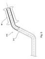
- a handlebar light alloy tube according to the present invention can have cross sections which are substantially constant along the tube itself (Figure 3) in shape and dimensions ⁇ namely in diameter, in case of circular cross-section light alloy tubes- or which vary according to different laws from the one, just described above, of the embodiment of Figures 1 and 2.
- a handlebar 111 is described, realised according to two variants of a third embodiment of the present invention.
- the handlebar 111 has a portion 125 substantially at the centre of each intermediate section 119,121 to which it is fixed a clamp 151 provided with a bracket 153 and with a fixing element, for instance a screw or a bolt 155, for fixing a transversal strengthening bar or crossbar 157 arranged substantially parallel to the central section 113.
- a clamp 151 provided with a bracket 153 and with a fixing element, for instance a screw or a bolt 155, for fixing a transversal strengthening bar or crossbar 157 arranged substantially parallel to the central section 113.
- the clamp 151 correspondingly presents an internal section with complementary taper in order to adapt itself to the taper of said central portion 125.
- said central portion 125 is realised cylindrical.
- said portion 125 being cylindrical at constant diameter, constitutes a zone suitable for fixing a clamp 151 of standard type with an inner section which is also cylindrical.
- the intermediate sections 119,121 will have two conical sections at their ends, that link themselves from the one side to the cylindrical portion 125 and to the other side to the inner 124 and external 126 bending zones respectively.
- the cylindrical portion 125 will be in this way comprised between the two conical sections.
- the handlebar according to this embodiment of the present invention thus having variable thickness and diameter and provided with a crossbar 157, turns out to be particularly suitable to be employed in protracted hard conditions and in all those cases where it is necessary a support to which steadily anchor auxiliary instruments like for instance the instruments necessary during the motorcycle rallies.
- tubular fixed sleeve 263 can be replaced, on one or both the ends of the light alloy tube, with a layer of a sliding material harder and more abrasion resistant than the light alloy of the tube.
- a layer of a sliding material harder and more abrasion resistant than the light alloy of the tube can be made for example by thermal- or electrochemical treatments of the light alloy tube.
Landscapes
- Engineering & Computer Science (AREA)
- Mechanical Engineering (AREA)
- Steering Devices For Bicycles And Motorcycles (AREA)
Priority Applications (1)
| Application Number | Priority Date | Filing Date | Title |
|---|---|---|---|
| EP04025288A EP1577204B1 (de) | 2004-03-15 | 2004-10-25 | Lenkstange für Fahrräder oder Motorräder |
Applications Claiming Priority (3)
| Application Number | Priority Date | Filing Date | Title |
|---|---|---|---|
| EP04425173 | 2004-03-15 | ||
| EP04425173A EP1577205B1 (de) | 2004-03-15 | 2004-03-15 | Lenker für Fahrräder und Motorräder |
| EP04025288A EP1577204B1 (de) | 2004-03-15 | 2004-10-25 | Lenkstange für Fahrräder oder Motorräder |
Publications (3)
| Publication Number | Publication Date |
|---|---|
| EP1577204A2 true EP1577204A2 (de) | 2005-09-21 |
| EP1577204A3 EP1577204A3 (de) | 2005-10-05 |
| EP1577204B1 EP1577204B1 (de) | 2007-08-29 |
Family
ID=34839792
Family Applications (1)
| Application Number | Title | Priority Date | Filing Date |
|---|---|---|---|
| EP04025288A Expired - Lifetime EP1577204B1 (de) | 2004-03-15 | 2004-10-25 | Lenkstange für Fahrräder oder Motorräder |
Country Status (1)
| Country | Link |
|---|---|
| EP (1) | EP1577204B1 (de) |
Cited By (2)
| Publication number | Priority date | Publication date | Assignee | Title |
|---|---|---|---|---|
| US7721623B2 (en) | 2004-03-15 | 2010-05-25 | Hi-Line S.R.L. | Handlebar for cycles and motorcycles |
| WO2017001239A1 (de) * | 2015-07-01 | 2017-01-05 | Bayerische Motoren Werke Aktiengesellschaft | Lenkeinrichtung |
Family Cites Families (7)
| Publication number | Priority date | Publication date | Assignee | Title |
|---|---|---|---|---|
| US2666340A (en) * | 1950-03-29 | 1954-01-19 | Hunt Wilde Corp | Handgrip |
| US5487709A (en) * | 1994-05-27 | 1996-01-30 | Thomas E. Froelich, Sr. | Adjustable rotating resistance exerciser |
| GB2321225B (en) * | 1997-01-18 | 2000-11-22 | Renthal Ltd | Handlebar |
| US6035742A (en) * | 1997-06-16 | 2000-03-14 | Valcor Concept Marketing, Inc. | Handlebar grip assembly |
| DE29801916U1 (de) * | 1998-02-05 | 1998-05-28 | Grätz, Michael, 87448 Waltenhofen | Lenkergriff |
| AU6393099A (en) * | 1998-10-13 | 2000-05-01 | Demarini Sports, Inc. | Handlebar system |
| US6652941B1 (en) * | 2000-09-27 | 2003-11-25 | Bic Corporation | Grip element and method of manufacture thereof |
-
2004
- 2004-10-25 EP EP04025288A patent/EP1577204B1/de not_active Expired - Lifetime
Cited By (2)
| Publication number | Priority date | Publication date | Assignee | Title |
|---|---|---|---|---|
| US7721623B2 (en) | 2004-03-15 | 2010-05-25 | Hi-Line S.R.L. | Handlebar for cycles and motorcycles |
| WO2017001239A1 (de) * | 2015-07-01 | 2017-01-05 | Bayerische Motoren Werke Aktiengesellschaft | Lenkeinrichtung |
Also Published As
| Publication number | Publication date |
|---|---|
| EP1577204A3 (de) | 2005-10-05 |
| EP1577204B1 (de) | 2007-08-29 |
Similar Documents
| Publication | Publication Date | Title |
|---|---|---|
| US7721623B2 (en) | Handlebar for cycles and motorcycles | |
| US9969459B2 (en) | Right crank arm assembly for a bicycle and crank arm and front sprocket thereof | |
| JP5451997B2 (ja) | 自転車の後輪用スプロケット・セットおよびスプロケット・アセンブリ | |
| US20090049949A1 (en) | Bicycle handlebar | |
| US7503239B2 (en) | Bicycle crank arm assembly | |
| EP1977965B1 (de) | Fahrradschnellspanner | |
| US6003890A (en) | Steering stop for bicycle fork suspension system | |
| US4424981A (en) | High strength light weight bike axle | |
| EP1958864A2 (de) | Fahrrad-Schnellspanner | |
| US20040237709A1 (en) | Crane structure for bicycle pedal | |
| EP1780111B2 (de) | Tretkurbellager-Anordnung | |
| US6149176A (en) | Bicycle shock absorber with multilayered shock absorbing members | |
| US20040251736A1 (en) | Central hub for a bicycle wheel and a bicycle wheel equipped with such hub | |
| US6209858B1 (en) | Bicycle shock absorber linked together through first and second annular members | |
| US8083246B2 (en) | Plated bicycle fork steerer tube | |
| US20060162482A1 (en) | Bicycle stem | |
| EP1577204B1 (de) | Lenkstange für Fahrräder oder Motorräder | |
| US6481700B1 (en) | Bicycle shock absorber with elastic members closely fitted between first and second rotating members | |
| EP2390111B1 (de) | Radspeichenanordnung eines Fahrrads | |
| WO2000021824A1 (en) | Handlebar system | |
| GB2321225A (en) | Handlebar | |
| EP3133008B1 (de) | Montagestruktur für griffgewicht eines sattelfahrzeugs | |
| US20140125033A1 (en) | Wrapped steerer tube suitable for a bicycle |
Legal Events
| Date | Code | Title | Description |
|---|---|---|---|
| PUAI | Public reference made under article 153(3) epc to a published international application that has entered the european phase |
Free format text: ORIGINAL CODE: 0009012 |
|
| PUAL | Search report despatched |
Free format text: ORIGINAL CODE: 0009013 |
|
| AK | Designated contracting states |
Kind code of ref document: A2 Designated state(s): AT BE BG CH CY CZ DE DK EE ES FI FR GB GR HU IE IT LI LU MC NL PL PT RO SE SI SK TR |
|
| AX | Request for extension of the european patent |
Extension state: AL HR LT LV MK |
|
| AK | Designated contracting states |
Kind code of ref document: A3 Designated state(s): AT BE BG CH CY CZ DE DK EE ES FI FR GB GR HU IE IT LI LU MC NL PL PT RO SE SI SK TR |
|
| AX | Request for extension of the european patent |
Extension state: AL HR LT LV MK |
|
| 17P | Request for examination filed |
Effective date: 20060216 |
|
| AKX | Designation fees paid |
Designated state(s): AT BE BG CH CY CZ DE DK EE ES FI FR GB GR HU IE IT LI LU MC NL PL PT RO SE SI SK TR |
|
| GRAP | Despatch of communication of intention to grant a patent |
Free format text: ORIGINAL CODE: EPIDOSNIGR1 |
|
| GRAS | Grant fee paid |
Free format text: ORIGINAL CODE: EPIDOSNIGR3 |
|
| GRAA | (expected) grant |
Free format text: ORIGINAL CODE: 0009210 |
|
| AK | Designated contracting states |
Kind code of ref document: B1 Designated state(s): AT BE BG CH CY CZ DE DK EE ES FI FR GB GR HU IE IT LI LU MC NL PL PT RO SE SI SK TR |
|
| REG | Reference to a national code |
Ref country code: GB Ref legal event code: FG4D |
|
| REG | Reference to a national code |
Ref country code: CH Ref legal event code: EP |
|
| REG | Reference to a national code |
Ref country code: IE Ref legal event code: FG4D |
|
| REF | Corresponds to: |
Ref document number: 602004008576 Country of ref document: DE Date of ref document: 20071011 Kind code of ref document: P |
|
| PG25 | Lapsed in a contracting state [announced via postgrant information from national office to epo] |
Ref country code: NL Free format text: LAPSE BECAUSE OF FAILURE TO SUBMIT A TRANSLATION OF THE DESCRIPTION OR TO PAY THE FEE WITHIN THE PRESCRIBED TIME-LIMIT Effective date: 20070829 Ref country code: FI Free format text: LAPSE BECAUSE OF FAILURE TO SUBMIT A TRANSLATION OF THE DESCRIPTION OR TO PAY THE FEE WITHIN THE PRESCRIBED TIME-LIMIT Effective date: 20070829 |
|
| NLV1 | Nl: lapsed or annulled due to failure to fulfill the requirements of art. 29p and 29m of the patents act | ||
| PG25 | Lapsed in a contracting state [announced via postgrant information from national office to epo] |
Ref country code: AT Free format text: LAPSE BECAUSE OF FAILURE TO SUBMIT A TRANSLATION OF THE DESCRIPTION OR TO PAY THE FEE WITHIN THE PRESCRIBED TIME-LIMIT Effective date: 20070829 Ref country code: PL Free format text: LAPSE BECAUSE OF FAILURE TO SUBMIT A TRANSLATION OF THE DESCRIPTION OR TO PAY THE FEE WITHIN THE PRESCRIBED TIME-LIMIT Effective date: 20070829 |
|
| PG25 | Lapsed in a contracting state [announced via postgrant information from national office to epo] |
Ref country code: BE Free format text: LAPSE BECAUSE OF FAILURE TO SUBMIT A TRANSLATION OF THE DESCRIPTION OR TO PAY THE FEE WITHIN THE PRESCRIBED TIME-LIMIT Effective date: 20070829 |
|
| REG | Reference to a national code |
Ref country code: CH Ref legal event code: NV Representative=s name: KEMIA SA |
|
| REG | Reference to a national code |
Ref country code: ES Ref legal event code: FG2A Ref document number: 2295756 Country of ref document: ES Kind code of ref document: T3 |
|
| ET | Fr: translation filed | ||
| PG25 | Lapsed in a contracting state [announced via postgrant information from national office to epo] |
Ref country code: DE Free format text: LAPSE BECAUSE OF FAILURE TO SUBMIT A TRANSLATION OF THE DESCRIPTION OR TO PAY THE FEE WITHIN THE PRESCRIBED TIME-LIMIT Effective date: 20071130 Ref country code: GR Free format text: LAPSE BECAUSE OF FAILURE TO SUBMIT A TRANSLATION OF THE DESCRIPTION OR TO PAY THE FEE WITHIN THE PRESCRIBED TIME-LIMIT Effective date: 20071130 Ref country code: DK Free format text: LAPSE BECAUSE OF FAILURE TO SUBMIT A TRANSLATION OF THE DESCRIPTION OR TO PAY THE FEE WITHIN THE PRESCRIBED TIME-LIMIT Effective date: 20070829 |
|
| PG25 | Lapsed in a contracting state [announced via postgrant information from national office to epo] |
Ref country code: CZ Free format text: LAPSE BECAUSE OF FAILURE TO SUBMIT A TRANSLATION OF THE DESCRIPTION OR TO PAY THE FEE WITHIN THE PRESCRIBED TIME-LIMIT Effective date: 20070829 Ref country code: SK Free format text: LAPSE BECAUSE OF FAILURE TO SUBMIT A TRANSLATION OF THE DESCRIPTION OR TO PAY THE FEE WITHIN THE PRESCRIBED TIME-LIMIT Effective date: 20070829 Ref country code: PT Free format text: LAPSE BECAUSE OF FAILURE TO SUBMIT A TRANSLATION OF THE DESCRIPTION OR TO PAY THE FEE WITHIN THE PRESCRIBED TIME-LIMIT Effective date: 20080129 Ref country code: MC Free format text: LAPSE BECAUSE OF NON-PAYMENT OF DUE FEES Effective date: 20071031 |
|
| PG25 | Lapsed in a contracting state [announced via postgrant information from national office to epo] |
Ref country code: SE Free format text: LAPSE BECAUSE OF FAILURE TO SUBMIT A TRANSLATION OF THE DESCRIPTION OR TO PAY THE FEE WITHIN THE PRESCRIBED TIME-LIMIT Effective date: 20071129 Ref country code: RO Free format text: LAPSE BECAUSE OF FAILURE TO SUBMIT A TRANSLATION OF THE DESCRIPTION OR TO PAY THE FEE WITHIN THE PRESCRIBED TIME-LIMIT Effective date: 20070829 |
|
| PLBE | No opposition filed within time limit |
Free format text: ORIGINAL CODE: 0009261 |
|
| STAA | Information on the status of an ep patent application or granted ep patent |
Free format text: STATUS: NO OPPOSITION FILED WITHIN TIME LIMIT |
|
| 26N | No opposition filed |
Effective date: 20080530 |
|
| PG25 | Lapsed in a contracting state [announced via postgrant information from national office to epo] |
Ref country code: IE Free format text: LAPSE BECAUSE OF NON-PAYMENT OF DUE FEES Effective date: 20071025 |
|
| PG25 | Lapsed in a contracting state [announced via postgrant information from national office to epo] |
Ref country code: EE Free format text: LAPSE BECAUSE OF FAILURE TO SUBMIT A TRANSLATION OF THE DESCRIPTION OR TO PAY THE FEE WITHIN THE PRESCRIBED TIME-LIMIT Effective date: 20070829 |
|
| REG | Reference to a national code |
Ref country code: CH Ref legal event code: PL Ref country code: CH Ref legal event code: AEN Free format text: IL BREVETTO E STATO RIATTIVATO SECONDO LA DOMANDA DI PROSEGUIMENTO DELLA PROCEDURA DELL' 8.05.2009 |
|
| PG25 | Lapsed in a contracting state [announced via postgrant information from national office to epo] |
Ref country code: SI Free format text: LAPSE BECAUSE OF FAILURE TO SUBMIT A TRANSLATION OF THE DESCRIPTION OR TO PAY THE FEE WITHIN THE PRESCRIBED TIME-LIMIT Effective date: 20070829 |
|
| PG25 | Lapsed in a contracting state [announced via postgrant information from national office to epo] |
Ref country code: CY Free format text: LAPSE BECAUSE OF FAILURE TO SUBMIT A TRANSLATION OF THE DESCRIPTION OR TO PAY THE FEE WITHIN THE PRESCRIBED TIME-LIMIT Effective date: 20070829 |
|
| PG25 | Lapsed in a contracting state [announced via postgrant information from national office to epo] |
Ref country code: BG Free format text: LAPSE BECAUSE OF FAILURE TO SUBMIT A TRANSLATION OF THE DESCRIPTION OR TO PAY THE FEE WITHIN THE PRESCRIBED TIME-LIMIT Effective date: 20071129 Ref country code: LU Free format text: LAPSE BECAUSE OF NON-PAYMENT OF DUE FEES Effective date: 20071025 |
|
| PG25 | Lapsed in a contracting state [announced via postgrant information from national office to epo] |
Ref country code: TR Free format text: LAPSE BECAUSE OF FAILURE TO SUBMIT A TRANSLATION OF THE DESCRIPTION OR TO PAY THE FEE WITHIN THE PRESCRIBED TIME-LIMIT Effective date: 20070829 Ref country code: HU Free format text: LAPSE BECAUSE OF FAILURE TO SUBMIT A TRANSLATION OF THE DESCRIPTION OR TO PAY THE FEE WITHIN THE PRESCRIBED TIME-LIMIT Effective date: 20080301 |
|
| PG25 | Lapsed in a contracting state [announced via postgrant information from national office to epo] |
Ref country code: IT Free format text: LAPSE BECAUSE OF NON-PAYMENT OF DUE FEES Effective date: 20091025 |
|
| PGRI | Patent reinstated in contracting state [announced from national office to epo] |
Ref country code: IT Effective date: 20110616 |
|
| PGFP | Annual fee paid to national office [announced via postgrant information from national office to epo] |
Ref country code: FR Payment date: 20121130 Year of fee payment: 9 |
|
| PGFP | Annual fee paid to national office [announced via postgrant information from national office to epo] |
Ref country code: ES Payment date: 20121030 Year of fee payment: 9 Ref country code: GB Payment date: 20121031 Year of fee payment: 9 Ref country code: IT Payment date: 20121030 Year of fee payment: 9 |
|
| PGFP | Annual fee paid to national office [announced via postgrant information from national office to epo] |
Ref country code: CH Payment date: 20130129 Year of fee payment: 9 Ref country code: DE Payment date: 20121220 Year of fee payment: 9 |
|
| REG | Reference to a national code |
Ref country code: CH Ref legal event code: PL |
|
| GBPC | Gb: european patent ceased through non-payment of renewal fee |
Effective date: 20131025 |
|
| PG25 | Lapsed in a contracting state [announced via postgrant information from national office to epo] |
Ref country code: CH Free format text: LAPSE BECAUSE OF NON-PAYMENT OF DUE FEES Effective date: 20131031 Ref country code: GB Free format text: LAPSE BECAUSE OF NON-PAYMENT OF DUE FEES Effective date: 20131025 Ref country code: LI Free format text: LAPSE BECAUSE OF NON-PAYMENT OF DUE FEES Effective date: 20131031 |
|
| REG | Reference to a national code |
Ref country code: FR Ref legal event code: ST Effective date: 20140630 |
|
| REG | Reference to a national code |
Ref country code: DE Ref legal event code: R119 Ref document number: 602004008576 Country of ref document: DE Effective date: 20140501 |
|
| PG25 | Lapsed in a contracting state [announced via postgrant information from national office to epo] |
Ref country code: DE Free format text: LAPSE BECAUSE OF FAILURE TO SUBMIT A TRANSLATION OF THE DESCRIPTION OR TO PAY THE FEE WITHIN THE PRESCRIBED TIME-LIMIT Effective date: 20140501 Ref country code: IT Free format text: LAPSE BECAUSE OF NON-PAYMENT OF DUE FEES Effective date: 20131025 Ref country code: FR Free format text: LAPSE BECAUSE OF NON-PAYMENT OF DUE FEES Effective date: 20131031 |
|
| REG | Reference to a national code |
Ref country code: ES Ref legal event code: FD2A Effective date: 20150703 |
|
| PG25 | Lapsed in a contracting state [announced via postgrant information from national office to epo] |
Ref country code: ES Free format text: LAPSE BECAUSE OF NON-PAYMENT OF DUE FEES Effective date: 20131026 |