EP1577103B1 - Image forming apparatus - Google Patents
Image forming apparatus Download PDFInfo
- Publication number
- EP1577103B1 EP1577103B1 EP05003188A EP05003188A EP1577103B1 EP 1577103 B1 EP1577103 B1 EP 1577103B1 EP 05003188 A EP05003188 A EP 05003188A EP 05003188 A EP05003188 A EP 05003188A EP 1577103 B1 EP1577103 B1 EP 1577103B1
- Authority
- EP
- European Patent Office
- Prior art keywords
- upper cover
- image forming
- cover member
- discharge tray
- recording medium
- Prior art date
- Legal status (The legal status is an assumption and is not a legal conclusion. Google has not performed a legal analysis and makes no representation as to the accuracy of the status listed.)
- Expired - Lifetime
Links
- 238000013459 approach Methods 0.000 claims 1
- 239000003086 colorant Substances 0.000 claims 1
- 238000000034 method Methods 0.000 description 7
- 238000012423 maintenance Methods 0.000 description 3
- 230000000694 effects Effects 0.000 description 2
- 238000004519 manufacturing process Methods 0.000 description 2
- UJRRDDHEMZLWFI-UHFFFAOYSA-N aminitrozole Chemical compound CC(=O)NC1=NC=C([N+]([O-])=O)S1 UJRRDDHEMZLWFI-UHFFFAOYSA-N 0.000 description 1
- 238000007599 discharging Methods 0.000 description 1
- 238000010348 incorporation Methods 0.000 description 1
- 238000009434 installation Methods 0.000 description 1
- 230000003287 optical effect Effects 0.000 description 1
- 230000003449 preventive effect Effects 0.000 description 1
- 230000000717 retained effect Effects 0.000 description 1
- 238000011144 upstream manufacturing Methods 0.000 description 1
Images


Classifications
-
- H—ELECTRICITY
- H04—ELECTRIC COMMUNICATION TECHNIQUE
- H04N—PICTORIAL COMMUNICATION, e.g. TELEVISION
- H04N1/00—Scanning, transmission or reproduction of documents or the like, e.g. facsimile transmission; Details thereof
- H04N1/00519—Constructional details not otherwise provided for, e.g. housings, covers
- H04N1/00525—Providing a more compact apparatus, e.g. sheet discharge tray in cover
-
- G—PHYSICS
- G03—PHOTOGRAPHY; CINEMATOGRAPHY; ANALOGOUS TECHNIQUES USING WAVES OTHER THAN OPTICAL WAVES; ELECTROGRAPHY; HOLOGRAPHY
- G03G—ELECTROGRAPHY; ELECTROPHOTOGRAPHY; MAGNETOGRAPHY
- G03G15/00—Apparatus for electrographic processes using a charge pattern
- G03G15/65—Apparatus which relate to the handling of copy material
- G03G15/6552—Means for discharging uncollated sheet copy material, e.g. discharging rollers, exit trays
-
- H—ELECTRICITY
- H04—ELECTRIC COMMUNICATION TECHNIQUE
- H04N—PICTORIAL COMMUNICATION, e.g. TELEVISION
- H04N1/00—Scanning, transmission or reproduction of documents or the like, e.g. facsimile transmission; Details thereof
- H04N1/00519—Constructional details not otherwise provided for, e.g. housings, covers
- H04N1/00525—Providing a more compact apparatus, e.g. sheet discharge tray in cover
- H04N1/0053—Discharge tray in cover
-
- H—ELECTRICITY
- H04—ELECTRIC COMMUNICATION TECHNIQUE
- H04N—PICTORIAL COMMUNICATION, e.g. TELEVISION
- H04N1/00—Scanning, transmission or reproduction of documents or the like, e.g. facsimile transmission; Details thereof
- H04N1/00519—Constructional details not otherwise provided for, e.g. housings, covers
- H04N1/00551—Top covers or the like
-
- B—PERFORMING OPERATIONS; TRANSPORTING
- B65—CONVEYING; PACKING; STORING; HANDLING THIN OR FILAMENTARY MATERIAL
- B65H—HANDLING THIN OR FILAMENTARY MATERIAL, e.g. SHEETS, WEBS, CABLES
- B65H2405/00—Parts for holding the handled material
- B65H2405/30—Other features of supports for sheets
- B65H2405/32—Supports for sheets partially insertable - extractable, e.g. upon sliding movement, drawer
- B65H2405/324—Supports for sheets partially insertable - extractable, e.g. upon sliding movement, drawer between operative position and non operative position
-
- B—PERFORMING OPERATIONS; TRANSPORTING
- B65—CONVEYING; PACKING; STORING; HANDLING THIN OR FILAMENTARY MATERIAL
- B65H—HANDLING THIN OR FILAMENTARY MATERIAL, e.g. SHEETS, WEBS, CABLES
- B65H2601/00—Problem to be solved or advantage achieved
- B65H2601/30—Facilitating or easing
- B65H2601/32—Facilitating or easing entities relating to handling machine
- B65H2601/321—Access
-
- G—PHYSICS
- G03—PHOTOGRAPHY; CINEMATOGRAPHY; ANALOGOUS TECHNIQUES USING WAVES OTHER THAN OPTICAL WAVES; ELECTROGRAPHY; HOLOGRAPHY
- G03G—ELECTROGRAPHY; ELECTROPHOTOGRAPHY; MAGNETOGRAPHY
- G03G2215/00—Apparatus for electrophotographic processes
- G03G2215/01—Apparatus for electrophotographic processes for producing multicoloured copies
- G03G2215/0103—Plural electrographic recording members
- G03G2215/0119—Linear arrangement adjacent plural transfer points
-
- G—PHYSICS
- G03—PHOTOGRAPHY; CINEMATOGRAPHY; ANALOGOUS TECHNIQUES USING WAVES OTHER THAN OPTICAL WAVES; ELECTROGRAPHY; HOLOGRAPHY
- G03G—ELECTROGRAPHY; ELECTROPHOTOGRAPHY; MAGNETOGRAPHY
- G03G2221/00—Processes not provided for by group G03G2215/00, e.g. cleaning or residual charge elimination
- G03G2221/16—Mechanical means for facilitating the maintenance of the apparatus, e.g. modular arrangements and complete machine concepts
- G03G2221/18—Cartridge systems
- G03G2221/183—Process cartridge
-
- H—ELECTRICITY
- H04—ELECTRIC COMMUNICATION TECHNIQUE
- H04N—PICTORIAL COMMUNICATION, e.g. TELEVISION
- H04N1/00—Scanning, transmission or reproduction of documents or the like, e.g. facsimile transmission; Details thereof
- H04N1/00519—Constructional details not otherwise provided for, e.g. housings, covers
- H04N1/00543—Allowing easy access, e.g. for maintenance or in case of paper jam
-
- H—ELECTRICITY
- H04—ELECTRIC COMMUNICATION TECHNIQUE
- H04N—PICTORIAL COMMUNICATION, e.g. TELEVISION
- H04N2201/00—Indexing scheme relating to scanning, transmission or reproduction of documents or the like, and to details thereof
- H04N2201/0077—Types of the still picture apparatus
- H04N2201/0094—Multifunctional device, i.e. a device capable of all of reading, reproducing, copying, facsimile transception, file transception
Definitions
- the disclosure relates to an image forming apparatus of a multifunctional machine having a printing function, a copying function, a scanning function and a facsimile function.
- US Patent No. 6,304,742 discloses a multifunction printer with a print engine, an input tray for original document sheets to be imaged, an output tray for those document sheets, and a copy sheet output tray for copy sheets from the print engine. All three trays are vertically superposed over one another and over the print engine, without substantially extending laterally of the print engine.
- a sheet discharge tray is often provided at a top of the printer.
- a rotatable lid is provided at a top of the printer. In the printer, the lid is open to replace consumable supplies, such as developing units, or clear a paper jam.
- the lid of the printer is open while printed sheets are placed on the sheet discharge tray, the printed sheets fall from the sheet discharge tray. Therefore, the printed sheets need to be temporarily removed from the sheet discharge tray every time the lid of the printer is open.
- Japanese examined Utility Model application No. 4-8132 discloses an image forming apparatus including a sheet support mechanism which supports printed sheets placed on a sheet discharge tray so as not to fall therefrom when a lid of the image forming apparatus is open.
- the sheet support mechanism includes a lever, a cam and a spring which are separately provided in an upper box of the image forming apparatus. If such a sheet support mechanism is adopted in a printer, the structure of the printer will be complicated and a parts count will be increased.
- the disclosure provides, among other things, an image forming apparatus that includes a simple sheet support device which prevents printed sheets from falling off a sheet discharge tray of a body casing therefrom, wherein the sheets printed in the body casing are discharged to a top of the body casing.
- an image forming apparatus includes a cover member that is capable of being opened and closed, wherein the cover member includes a discharge tray that is capable of holding printed recording medium, and an automatic document reader that is provided above the discharge tray, wherein when the cover member is opened to a predetermined position, the automatic document reader supports the printed recording medium placed on the discharge tray so that the printed recording medium does not fall therefrom when the cover member is open
- an image forming apparatus includes a body that stores therein an image forming portion, a cover member that is attached to the body at a first end of the cover member and is capable of being opened and closed by rotating about the first end, wherein the cover member includes a discharge tray that is capable of holding printed recording medium, and an automatic document reader that is provided above the discharge tray and attached to the cover member at the first end of the cover member, wherein the automatic document reader extends from the first end and covers a part of the discharge tray.
- FIG. 1 is a perspective view of a color printer having a scanning function according to an exemplary embodiment of an image forming apparatus of the disclosure
- FIG. 2A is a side view showing essential parts of the color printer of FIG. 1 , wherein an upper cover is closed;
- FIG. 2B is a side view showing essential parts of the color printer of FIG. 1 , wherein the upper cover is open;
- FIGS. 3A and 3B represent a color printer according to an exemplary embodiment of the disclosure
- FIGS. 4A and 4B represent a color printer according to an exemplary embodiment of the disclosure
- FIGS. 5A and 5B represent a color printer according to an exemplary embodiment of the disclosure
- FIGS. 6A and 6B represent a color printer according to an exemplary embodiment of the disclosure
- FIGS. 7A and 7B represent a color printer according to an exemplary embodiment of the disclosure
- FIGS. 8A and 8B represent a color printer according to an exemplary embodiment of the disclosure
- FIG. 9 illustrates a document discharge tray
- FIG. 10 represents a color printer according to an exemplary embodiment of the disclosure.
- FIG. 1 is a perspective view of a color printer 1 having a scanning function, as an image forming apparatus, according to a first exemplary embodiment.
- a document is inserted from the left and is conveyed to the right in FIG. 1 .
- a sheet is discharged from the color printer 1 to the right in FIG. 1 .
- a user operates the color printer 1 from the right in FIG. 1 .
- the upper side in FIG. 1 is referred to as an upper side of the color printer 1.
- the lower side in FIG. 1 is referred to as a lower side of the color printer 1.
- the near side in FIG. 1 is referred to as the left side of the color printer 1.
- the far side in FIG. 1 which is an opposite side to the near side, is referred to as the right side of the color printer 1.
- the color printer 1 includes a printing device 4 and an automatic document reader 20.
- an upper cover 6 is provided at a top of the printing device 4.
- the upper cover 6 has a cover shaft 8 on an upstream side in a document conveying direction.
- the upper cover 6 rotates about the cover shaft 8 to be opened and closed.
- a printed sheet discharge tray 9 is provided as a part of the upper cover 6.
- the automatic document reader 20 is provided on a cover top face 6a of the upper cover 6, that is, above the sheet discharge tray 9.
- a sheet feed cassette 19 is provided at a bottom of the printing device 4, in order to store sheets 3 therein.
- the sheet feed cassette 19 is detachably attachable to a body casing 2 of the color printer 1 from a side which is the same as the downstream side in the sheet discharge direction.
- the automatic document reader 20 includes at least a document feed tray 21, a document discharge tray 22 having a tip 22a, and a document reading portion 23.
- the document reading portion 23 is provided between the document feed tray 21 and the document discharge tray 22.
- the document reading portion 23 is a feeder-type reading portion that reads a document while the document is being conveyed with respect to a fixed reading sensor (an optical sensor).
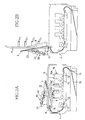
- FIGS. 2A and 2B are side views showing essential parts of the color printer 1 of FIG. 1 .
- FIG. 2A illustrates the color printer 1 with its upper cover 6 closed.
- FIG. 2B illustrates the color printer 1 with its upper cover 6 open.
- the sheet feed cassette 19 includes a sheet feed tray 10 and a sheet supply roller 11.
- a sheet 3 is fed to an image forming portion 15 from the sheet feed tray 10 by the sheet supply roller 11.
- the sheet 3 is placed on a conveyor belt 14, which is wound around conveyor rollers 12, 13, and is conveyed by rotation of the conveyor belt 14.
- a plurality of developing agent images are transferred onto the sheet 3 by process units 16M, 16C, 16Y, 16BK, which are provided and aligned by color.
- a fixing portion 17 the developed images transferred onto the sheet 3 are thermally fixed thereon.
- the sheet 3 passed through the fixing portion 17 is then discharged onto the sheet discharge tray 9 by a sheet discharge roller 18.
- the discharge direction of the sheet 3 to be discharged onto the sheet discharge tray 9 is the same as the discharge direction of the document to be discharged onto the document discharge tray 22. Therefore, the sheet 3 and the document can be taken out of the respective discharge trays 9, 22 from the same side of the body casing 2, so that user operability can be increased.
- the sheet feed cassette 19 can be attached to and detached from the body casing 2 from the same side as the sheet discharge direction in the sheet discharge tray 9. Accordingly, the user operability can be further improved.
- the printed sheets 3 are supported by the document reading portion 23 and the document discharge tray 22 of the automatic document reader 20, so that the sheets 3 do not fall from the sheet discharge tray 9.
- the upper cover 6 is rotated to a position where the upper cover 6 extends substantially in a upright direction, so that a replenishing or replacing of developing agent for the process units 16M, 16C, 16Y, 16BK disposed under the upper cover 6 can be easily performed.
- the upper cover 6 is rotated upward from the side near to the user. Accordingly, the user can easily access and operate the image forming portion 15 in the body casing 2 without obstacles, such as the automatic document reader 20, by opening the upper cover 6.
- the replenishing or replacing of developing agent maintenance can be easily and speedily performed while preventing the fall of a sheet caused by the opening of the upper cover 6, even when the sheet is placed on the sheet discharge tray 9.
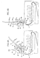
- FIGS. 3A to 4B A second exemplary embodiment of the disclosure will be described with reference to FIGS. 3A to 4B .
- the same parts or portions are designated by the same reference numerals as those in FIGS. 2A and 2B , and explanations for those parts or portions will be omitted.
- the document reading portion 23 of the second exemplary embodiment can rotate about a fixed shaft 24 by a predetermined angle in a direction which the document reading portion 23 moves away from the upper cover 6.
- a guide slot 26 is provided at at least one side (the left side of the color printer 1) of the upper cover 6 so as to extend along the upper cover 6.
- the guide slot 26 is an elongated hole that linearly extends substantially in parallel with the upper cover 6 when the upper cover 6 is closed.
- the cover arm 25 has an cover arm hinge 25a at one end and a cover arm roller 25b at another end.
- the cover arm hinge 25a is fixed to the body casing 2 of the printing device 4.
- the cover arm roller 25b is engaged with the guide slot 26 and can slide along the guide slot 26.
- the cover arm 25 rotates about the cover arm hinge 25a. In accordance with the rotation of the cover arm 25, the cover arm roller 25b slides in the front and back directions in the guide slot 26.
- the guide arm 27 has a guide arm hinge 27a at one end and a guide arm roller 27b at another end.
- the guide arm hinge 27a is fixed to the automatic document reader 20.
- the guide arm roller 27b is engaged with the guide slot 26 and can slide along the guide slot 26. Therefore, the guide arm 27 rotates about the guide arm hinge 27a. In accordance with rotation of the guide arm 27, the guide arm roller 27b slides along the guide slot 26.
- the automatic document reader 20 can be rotated (open) upward by a predetermined angle. Accordingly, the printed sheets 3 placed on the sheet discharge tray 9 can be easily removed therefrom. In particular, the removal of a small-sized sheet 3 therefrom is easier to perform.
- the guide slot 26 is provided with a click resistance applying device that slightly applies a click resistance to the guide arm roller 27b when the guide arm roller 27b is located at a position shown in FIG. 4B .
- the automatic document reader 20 can be temporarily retained at an upright position of FIG. 4B . By sliding the guide arm roller 27b by a force stronger than the click resistance, the retainment of the automatic document reader 20 can be easily released.
- the rotating direction of the guide arm 27 is a direction which the automatic document reader 20, which is in the state shown in FIG. 4A , is rotated toward the upper cover 6. That is, in conjunction with the opening of the upper cover 6 in the state where the automatic document reader 20 is upwardly rotated (opened), the automatic document reader 20 moves to a proximity position with respect to the sheet discharge tray 9. That is, the automatic document reader 20 is automatically rotated downward (closed) as the upper cover 6 opens. Then, the tip 22a of the document discharge tray 22 is brought closer to the upper surface of the upper cover 6.
- the cover arm roller 25b of the cover arm 25 pushes and slides the guide arm roller 27b of the guide arm 27 to the end of the guide slot 26 on the cover shaft 8 side. Therefore, the guide arm 27 rotates about the guide arm hinge 27a, so that the tip 22a of the document discharge tray 22 of the automatic document reader 20 is located at the nearest position with respect to the upper cover 6.
- the sheet 3 is supported by the document reading portion 23 and the document discharge tray 22 of the automatic document reader 20, so that the sheet 3 does not fall from the sheet discharge tray 9.
- the cover arm 25, the guide slot 26 and the guide arm 27 are provided at the left end of the upper cover 6.
- the cover arm 25, the guide slot 26 and the guide arm 27 may be provided at both right and left ends of the upper cover 6.
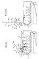
- FIGS. 5A to 6B a third exemplary embodiment of the disclosure will be described with reference to FIGS. 5A to 6B .
- the same parts or portions are designated by the same reference numerals as those in FIGS. 2A and 2B , and explanations for those parts or portions will be omitted.
- a substantially straight lever 31 is provided on at least one side (a left side in the third exemplary embodiment) of the body casing 2 of the printing device 4.
- the lever 31 has a lever hinge 31a at a substantially center portion of the lever 31 in its longitudinal direction.
- the lever hinge 31a is fixed to the body casing 2 of the printing device 4. Therefore, the lever 31 can swing in the up and down directions about the lever hinge 31a.
- the lever 31 has a lever protrusion 31b at one end and a lever cutaway portion 31c at another end.
- a spring 32 is attached to the lever cutaway portion 31c so as to pull the lever cutaway portion 31c of the lever 31 downward. With this structure, the lever protrusion 31b of the lever 31 is urged upward about the lever hinge 31a by the spring 32.
- the document reading portion 23 of the automatic document reader 20 is provided with a first notch 35 and a second notch 36 at same radial positions about the fixed shaft 24 such that the first and second notches 35, 36 face the lever protrusion 31b of the lever 31.
- a damper gear 38 is provided so as to be rotatable about a shaft (not shown) fixed to the document reading portion 23 of the automatic document reader 20.
- the damper gear 38 is engaged with a side gear 37 fixedly provided to the upper cover 6.
- the damper gear 38 moves around the side gear 37 while itself rotating when the automatic document reader 20 is opened and closed with respect to the upper cover 6.
- the damper gear 38 is provided with, for example, a damper material having an appropriate viscosity, at its rotating portion. With this structure, the damper gear 38 exerts its damper effect to make its rotation slow when the damper gear 38 tries to suddenly rotate.
- a guide spring 39 is provided between the document reading portion 23 of the automatic document 20 and the upper cover 6. An one end of the guide spring 39 is caught by a side hook 41 ( FIG. 5B ) provided to the document reading portion 23 of the automatic document reader 20, and another end is caught by a cover hook 6b ( FIG. 5B ) provided to the upper cover 6. With this structure, the guide spring 39 urges the document reading portion 23 of the automatic document reader 20 toward the upper cover 6.
- the automatic document reader 20 can be upwardly rotated by a predetermined angle against an urging force from the guide spring 39, from the state of FIG. 5A . Then, the document reading portion 23 rotates counterclockwise about the fixing shaft 24, so that the first notch 35 is engaged with the lever protrusion 31 b of the lever 31. Therefore, a printed sheet 3 placed on the sheet discharge tray 9 can be easily removed therefrom. In particular, the removal of a small-sized sheet 3 therefrom is easier to perform.
- the lever 31, the side gear 37 and the damper gear 38 are provided at the left end of the upper cover 6.
- the lever 31, the side gear 37 and the damper gear 38 may be provided on both right and left ends of the upper cover 6 as necessary.
- a color printer 1 of the fourth exemplary embodiment includes a locking mechanism for the automatic document reader 20, based on the color printer 1 of the third exemplary embodiment.
- a hook 45 is provided on at least one side of the upper cover 6.
- the hook 45 has a substantially L-shape and includes as a pawl portion 45b at an end of one side.
- the hook 45 is provided so at to be rotatable about a hook hinge 45a, wherein an end 45c, which is opposite to the end having the pawl portion 45b of the hook 45, is urged by a torsion spring 46 attached to the hook hinge 45a so as to rotate downwardly.
- the automatic document reader 20 opposite to the hook 45 has a boss 47 at a position where the boss 47 can be engaged with the pawl portion 45b of the hook 45.
- the automatic document reader 20 can be rotated or opened upward by a predetermined angle against the urging force from the guide spring 39. Therefore, a printed sheet 3 placed on the sheet discharge tray 9 can be easily removed therefrom. In particular, the removal of a small-sized sheet 3 therefrom is easier to perform.
- the upper cover 6 is closed, so that the pawl portion 45b of the hook 45 is not in engagement with the boss 47.
- FIG. 9 represents a shape of the document discharge tray 22.
- the document discharge tray 22 has a U-shaped cutaway portion 22b opening toward the document discharging direction.
- the document discharge tray 22 may have a V-shaped cutaway portion. With this shape, any-sized document placed on the document discharge tray 9 provided to the upper cover 6 can be easily removed therefrom through the U-shaped or V-shaped cutaway portion even when the automatic document feeder 20 is closed.
- a printed sheet 3 placed on the sheet discharge tray 9 can be surely support by the document discharge tray 22 even when the upper cover 6 is open.
- the color printer 1 does not require a special sheet drop preventive mechanism to be separately equipped because the fall of the printed sheets 3 is prevented by the document reading portion 23 and the document discharge tray 22. Therefore, the manufacturing cost of the color printer 1 is not increased.
- the document reading portion 23 and the document discharge tray 22 of the automatic document reader 20 function as a recording medium support device.
- the cover arm 25, the guide slot 26 and guide arm 27 of the second exemplary embodiment, and the lever 21, the side gear 37 and the guide spring 39 of the third exemplary embodiment function as an interlock mechanism.
- the hook 45, the torsion spring 45 and the boss 47 of the fourth exemplary embodiment function as a locking mechanism.
- a portion of the sheet discharge tray 9 that holds sheets 3 is located below a portion of the document reading portion 23 that contacts the upper cover 6.
- the sheet discharge tray 9 can be located to the right of the portion of the document reading portion 23 that contacts the upper cover 6.
- a thicker upper cover 6 can be provided such that the sheet discharge tray 9 does not protrude below a flat portion of the upper cover 6.
- the printed recording medium placed on the discharge tray is supported by the automatic document feeder, so that the printed recording medium does not fall from the discharge tray:
- any other special recording medium support device other than the automatic document reader is provided, so that a parts count and a manufacturing cost of the image forming apparatus are not increased.
- the structure of the image forming apparatus does not become complicated due to the provision of the recording medium support device for supporting a recording medium placed on the recording medium discharge tray to prevent the recording medium from falling therefrom.
- a printed recording medium placed on the discharge tray provided under the automatic document reader can be easily removed therefrom.
- a small-sized recording medium placed on the discharge tray provided under the automatic document reader can be easily removed therefrom.
- a printed recording medium placed on the discharge tray can be surely prevented from falling therefrom by employing at least one of the document reading portion and the document discharge tray of the automatic document reader.
- the cover member is upwardly rotated to the substantially upright position, so that the check, maintenance and replacement of the image forming device, for example, a process unit, disposed under the cover member can be easily performed.
- the automatic document reader can be moved to the position near the discharge tray in conjunction with the opening of the cover member. Accordingly, it is unnecessary to perform an operation to return the automatic document reader to the near position in advance before the cover member is rotated upward to be open. In addition, it can be prevented that the cover member is opened with the automatic document reader returned to the near position.
- the automatic document reader is locked so as not to rotate while positioned at the nearest position with respect to the discharge tray when the cover member is located at the substantially upright position. Therefore, the automatic document reader can be prevented from rotating accidentally.
- a printed recording medium placed on the discharge tray can be easily removed therefrom through the U- or V-shaped cutaway portion which is open toward the document discharge direction in the document discharge tray.
- the recording medium placed on the discharge tray can be surely supported when the cover member is open.
- the recording medium discharge direction and the document discharge direction are the same. Therefore, the printed recording medium and the document can be removed from the respective discharge trays from the same side of the body casing. Thus, user operability is increased.
- the recording medium cassette can be also attached to and detached from the body casing from the same side of the body casing, so that the user operability is further increased.
- the image forming apparatus including the so-called tandem color printer and the automatic document feeder
- a user can easily access or operate the image forming device in the body casing without being interfered with the automatic document reader. Accordingly, the replenishment of developing agent and replacement of the image forming device can be easily performed.
- the fall of the recording medium caused by the opening of the cover member is prevented, so that the maintenance can be easily and speedily performed.
Landscapes
- Engineering & Computer Science (AREA)
- Multimedia (AREA)
- Signal Processing (AREA)
- Physics & Mathematics (AREA)
- General Physics & Mathematics (AREA)
- Facsimiles In General (AREA)
- Electrophotography Configuration And Component (AREA)
- Accessory Devices And Overall Control Thereof (AREA)
- Pile Receivers (AREA)
- Photographic Developing Apparatuses (AREA)
- Printers Or Recording Devices Using Electromagnetic And Radiation Means (AREA)
- Forging (AREA)
Abstract
Description
- The disclosure relates to an image forming apparatus of a multifunctional machine having a printing function, a copying function, a scanning function and a facsimile function.
US Patent No. 6,304,742 discloses a multifunction printer with a print engine, an input tray for original document sheets to be imaged, an output tray for those document sheets, and a copy sheet output tray for copy sheets from the print engine. All three trays are vertically superposed over one another and over the print engine, without substantially extending laterally of the print engine. - Conventionally, in a printer of a multifunctional machine having a printing function, a copying function, a scanning function and a facsimile function, for the sake of saving installation space for the printer, a sheet discharge tray is often provided at a top of the printer. For example, in a tandem-type laser beam printer, a rotatable lid is provided at a top of the printer. In the printer, the lid is open to replace consumable supplies, such as developing units, or clear a paper jam.
- However, if the lid of the printer is open while printed sheets are placed on the sheet discharge tray, the printed sheets fall from the sheet discharge tray. Therefore, the printed sheets need to be temporarily removed from the sheet discharge tray every time the lid of the printer is open.
-
Japanese examined Utility Model application No. 4-8132 JP63035757U - The disclosure provides, among other things, an image forming apparatus that includes a simple sheet support device which prevents printed sheets from falling off a sheet discharge tray of a body casing therefrom, wherein the sheets printed in the body casing are discharged to a top of the body casing.
- According to one exemplary aspect of disclosure, an image forming apparatus includes a cover member that is capable of being opened and closed, wherein the cover member includes a discharge tray that is capable of holding printed recording medium, and an automatic document reader that is provided above the discharge tray, wherein when the cover member is opened to a predetermined position, the automatic document reader supports the printed recording medium placed on the discharge tray so that the printed recording medium does not fall therefrom when the cover member is open
- According to one exemplary aspect of disclosure, an image forming apparatus includes a body that stores therein an image forming portion, a cover member that is attached to the body at a first end of the cover member and is capable of being opened and closed by rotating about the first end, wherein the cover member includes a discharge tray that is capable of holding printed recording medium, and an automatic document reader that is provided above the discharge tray and attached to the cover member at the first end of the cover member, wherein the automatic document reader extends from the first end and covers a part of the discharge tray.
- Exemplary embodiments of the disclosure will be described in detail with reference to the following figures wherein:
-
FIG. 1 is a perspective view of a color printer having a scanning function according to an exemplary embodiment of an image forming apparatus of the disclosure; -
FIG. 2A is a side view showing essential parts of the color printer ofFIG. 1 , wherein an upper cover is closed; -
FIG. 2B is a side view showing essential parts of the color printer ofFIG. 1 , wherein the upper cover is open; -
FIGS. 3A and 3B represent a color printer according to an exemplary embodiment of the disclosure; -
FIGS. 4A and 4B represent a color printer according to an exemplary embodiment of the disclosure; -
FIGS. 5A and 5B represent a color printer according to an exemplary embodiment of the disclosure; -
FIGS. 6A and 6B represent a color printer according to an exemplary embodiment of the disclosure; -
FIGS. 7A and 7B represent a color printer according to an exemplary embodiment of the disclosure; -
FIGS. 8A and 8B represent a color printer according to an exemplary embodiment of the disclosure; -
FIG. 9 illustrates a document discharge tray; and -
FIG. 10 represents a color printer according to an exemplary embodiment of the disclosure. - Exemplary embodiments of the disclosure will be described with reference to the accompanying drawings.
FIG. 1 is a perspective view of a color printer 1 having a scanning function, as an image forming apparatus, according to a first exemplary embodiment. - In the exemplary embodiments described below, a document is inserted from the left and is conveyed to the right in
FIG. 1 . A sheet is discharged from the color printer 1 to the right inFIG. 1 . A user operates the color printer 1 from the right inFIG. 1 . Throughout the specification, the upper side inFIG. 1 is referred to as an upper side of the color printer 1. The lower side inFIG. 1 is referred to as a lower side of the color printer 1. The near side inFIG. 1 is referred to as the left side of the color printer 1. The far side inFIG. 1 , which is an opposite side to the near side, is referred to as the right side of the color printer 1. - As shown in
FIG. 1 , the color printer 1 includes aprinting device 4 and anautomatic document reader 20. At a top of theprinting device 4, anupper cover 6 is provided. Theupper cover 6 has acover shaft 8 on an upstream side in a document conveying direction. Theupper cover 6 rotates about thecover shaft 8 to be opened and closed. To open theupper cover 6, acover handle 7, which is provided to theupper cover 6 on a downstream side in a sheet discharge direction, is pulled upward. A printedsheet discharge tray 9 is provided as a part of theupper cover 6. Theautomatic document reader 20 is provided on a covertop face 6a of theupper cover 6, that is, above thesheet discharge tray 9. - At a bottom of the
printing device 4, asheet feed cassette 19 is provided in order to storesheets 3 therein. Thesheet feed cassette 19 is detachably attachable to abody casing 2 of the color printer 1 from a side which is the same as the downstream side in the sheet discharge direction. - The
automatic document reader 20 includes at least adocument feed tray 21, adocument discharge tray 22 having atip 22a, and adocument reading portion 23. Thedocument reading portion 23 is provided between thedocument feed tray 21 and thedocument discharge tray 22. Thedocument reading portion 23 is a feeder-type reading portion that reads a document while the document is being conveyed with respect to a fixed reading sensor (an optical sensor). -
FIGS. 2A and 2B are side views showing essential parts of the color printer 1 ofFIG. 1 .FIG. 2A illustrates the color printer 1 with itsupper cover 6 closed.FIG. 2B illustrates the color printer 1 with itsupper cover 6 open. - Referring to
FIG. 2A , an outline of a printing path of thesheet 3 as a recording medium will be described below. - The
sheet feed cassette 19 includes asheet feed tray 10 and asheet supply roller 11. InFIG. 2A , asheet 3 is fed to animage forming portion 15 from thesheet feed tray 10 by thesheet supply roller 11. At theimage forming portion 15, thesheet 3 is placed on aconveyor belt 14, which is wound aroundconveyor rollers conveyor belt 14. While thesheet 3 is being conveyed by theconveyor belt 14, a plurality of developing agent images are transferred onto thesheet 3 byprocess units portion 17, the developed images transferred onto thesheet 3 are thermally fixed thereon. Thesheet 3 passed through the fixingportion 17 is then discharged onto thesheet discharge tray 9 by asheet discharge roller 18. - In a state of
FIG. 2A , the discharge direction of thesheet 3 to be discharged onto thesheet discharge tray 9 is the same as the discharge direction of the document to be discharged onto thedocument discharge tray 22. Therefore, thesheet 3 and the document can be taken out of therespective discharge trays body casing 2, so that user operability can be increased. - In addition, as described above, the
sheet feed cassette 19 can be attached to and detached from thebody casing 2 from the same side as the sheet discharge direction in thesheet discharge tray 9. Accordingly, the user operability can be further improved. - In a state of
FIG. 2B , the printedsheets 3 are supported by thedocument reading portion 23 and thedocument discharge tray 22 of theautomatic document reader 20, so that thesheets 3 do not fall from thesheet discharge tray 9. In addition, theupper cover 6 is rotated to a position where theupper cover 6 extends substantially in a upright direction, so that a replenishing or replacing of developing agent for theprocess units upper cover 6 can be easily performed. Theupper cover 6 is rotated upward from the side near to the user. Accordingly, the user can easily access and operate theimage forming portion 15 in thebody casing 2 without obstacles, such as theautomatic document reader 20, by opening theupper cover 6. Thus, as well as the replenishing or replacing of developing agent, maintenance can be easily and speedily performed while preventing the fall of a sheet caused by the opening of theupper cover 6, even when the sheet is placed on thesheet discharge tray 9. - A second exemplary embodiment of the disclosure will be described with reference to
FIGS. 3A to 4B . The same parts or portions are designated by the same reference numerals as those inFIGS. 2A and 2B , and explanations for those parts or portions will be omitted. - In
FIG. 3A , thedocument reading portion 23 of the second exemplary embodiment can rotate about a fixedshaft 24 by a predetermined angle in a direction which thedocument reading portion 23 moves away from theupper cover 6. Aguide slot 26 is provided at at least one side (the left side of the color printer 1) of theupper cover 6 so as to extend along theupper cover 6. Theguide slot 26 is an elongated hole that linearly extends substantially in parallel with theupper cover 6 when theupper cover 6 is closed. - A
cover arm 25, which is a substantially straight member, is provided on theprinting device 4 side. Thecover arm 25 has ancover arm hinge 25a at one end and acover arm roller 25b at another end. Thecover arm hinge 25a is fixed to thebody casing 2 of theprinting device 4. Thecover arm roller 25b is engaged with theguide slot 26 and can slide along theguide slot 26. Thecover arm 25 rotates about thecover arm hinge 25a. In accordance with the rotation of thecover arm 25, thecover arm roller 25b slides in the front and back directions in theguide slot 26. - As shown in
FIG. 3A , aguide arm 27, which is a substantially straight member, is provided on theautomatic document reader 20 side. Theguide arm 27 has aguide arm hinge 27a at one end and aguide arm roller 27b at another end. Theguide arm hinge 27a is fixed to theautomatic document reader 20. Theguide arm roller 27b is engaged with theguide slot 26 and can slide along theguide slot 26. Therefore, theguide arm 27 rotates about theguide arm hinge 27a. In accordance with rotation of theguide arm 27, theguide arm roller 27b slides along theguide slot 26. - As shown in
FIG. 3B , in the state where theupper cover 6 of theprinting device 4 is closed, theautomatic document reader 20 can be rotated (open) upward by a predetermined angle. Accordingly, the printedsheets 3 placed on thesheet discharge tray 9 can be easily removed therefrom. In particular, the removal of a small-sized sheet 3 therefrom is easier to perform. Theguide slot 26 is provided with a click resistance applying device that slightly applies a click resistance to theguide arm roller 27b when theguide arm roller 27b is located at a position shown inFIG. 4B . Theautomatic document reader 20 can be temporarily retained at an upright position ofFIG. 4B . By sliding theguide arm roller 27b by a force stronger than the click resistance, the retainment of theautomatic document reader 20 can be easily released. - When the
upper cover 6 is further rotated upward (in a direction indicated by an arrow U inFIG. 4A ) from the state ofFIG. 3B , thecover arm roller 25b of thecover arm 25 slides in a direction toward thecover shaft 8 along theguide slot 26 as shown inFIG. 4A . When thecover arm roller 25b of thecover arm 25 abuts against theguide arm roller 27b of theguide arm 27 in theguide slot 26, thecover arm roller 25b pushes and slides theguide arm roller 27b toward thecover shaft 8 along theguide slot 26. - When the
guide arm roller 27b slides toward thecover shaft 8 along theguide slot 26, theguide arm 27 rotates about theguide arm hinge 27a. The rotating direction of theguide arm 27 is a direction which theautomatic document reader 20, which is in the state shown inFIG. 4A , is rotated toward theupper cover 6. That is, in conjunction with the opening of theupper cover 6 in the state where theautomatic document reader 20 is upwardly rotated (opened), theautomatic document reader 20 moves to a proximity position with respect to thesheet discharge tray 9. That is, theautomatic document reader 20 is automatically rotated downward (closed) as theupper cover 6 opens. Then, thetip 22a of thedocument discharge tray 22 is brought closer to the upper surface of theupper cover 6. - As described above, when the
upper cover 6 is upwardly open as shown inFIG. 4B , thecover arm roller 25b of thecover arm 25 pushes and slides theguide arm roller 27b of theguide arm 27 to the end of theguide slot 26 on thecover shaft 8 side. Therefore, theguide arm 27 rotates about theguide arm hinge 27a, so that thetip 22a of thedocument discharge tray 22 of theautomatic document reader 20 is located at the nearest position with respect to theupper cover 6. - As a result, in the state of
FIG. 4B , thesheet 3 is supported by thedocument reading portion 23 and thedocument discharge tray 22 of theautomatic document reader 20, so that thesheet 3 does not fall from thesheet discharge tray 9. - When the
upper cover 6, which is upwardly rotated as shown inFIG. 4B , is rotated downward about thecover shaft 8 to be closed, thecover arm 25 and theguide arm 27 slide in the direction reverse to the direction when theupper cover 6 is opened. Thus, theupper cover 6 can be returned to the state ofFIG. 3A . - In the second exemplary embodiment, the
cover arm 25, theguide slot 26 and theguide arm 27 are provided at the left end of theupper cover 6. However, thecover arm 25, theguide slot 26 and theguide arm 27 may be provided at both right and left ends of theupper cover 6. - Next, a third exemplary embodiment of the disclosure will be described with reference to
FIGS. 5A to 6B . The same parts or portions are designated by the same reference numerals as those inFIGS. 2A and 2B , and explanations for those parts or portions will be omitted. - As shown in
FIG. 5A , a substantiallystraight lever 31 is provided on at least one side (a left side in the third exemplary embodiment) of thebody casing 2 of theprinting device 4. Thelever 31 has alever hinge 31a at a substantially center portion of thelever 31 in its longitudinal direction. Thelever hinge 31a is fixed to thebody casing 2 of theprinting device 4. Therefore, thelever 31 can swing in the up and down directions about thelever hinge 31a. - The
lever 31 has alever protrusion 31b at one end and alever cutaway portion 31c at another end. Aspring 32 is attached to thelever cutaway portion 31c so as to pull thelever cutaway portion 31c of thelever 31 downward. With this structure, thelever protrusion 31b of thelever 31 is urged upward about thelever hinge 31a by thespring 32. - The
document reading portion 23 of theautomatic document reader 20 is provided with afirst notch 35 and asecond notch 36 at same radial positions about the fixedshaft 24 such that the first andsecond notches lever protrusion 31b of thelever 31. - A
damper gear 38 is provided so as to be rotatable about a shaft (not shown) fixed to thedocument reading portion 23 of theautomatic document reader 20. Thedamper gear 38 is engaged with aside gear 37 fixedly provided to theupper cover 6. Thedamper gear 38 moves around theside gear 37 while itself rotating when theautomatic document reader 20 is opened and closed with respect to theupper cover 6. Thedamper gear 38 is provided with, for example, a damper material having an appropriate viscosity, at its rotating portion. With this structure, thedamper gear 38 exerts its damper effect to make its rotation slow when thedamper gear 38 tries to suddenly rotate. - A
guide spring 39 is provided between thedocument reading portion 23 of theautomatic document 20 and theupper cover 6. An one end of theguide spring 39 is caught by a side hook 41 (FIG. 5B ) provided to thedocument reading portion 23 of theautomatic document reader 20, and another end is caught by acover hook 6b (FIG. 5B ) provided to theupper cover 6. With this structure, theguide spring 39 urges thedocument reading portion 23 of theautomatic document reader 20 toward theupper cover 6. - As shown in
FIG. 5A , thelever protrusion 31b of thelever 31 is engaged with thesecond notch 36 in the state where theupper cover 6 is closed. - As shown in
FIG. 5B , theautomatic document reader 20 can be upwardly rotated by a predetermined angle against an urging force from theguide spring 39, from the state ofFIG. 5A . Then, thedocument reading portion 23 rotates counterclockwise about the fixingshaft 24, so that thefirst notch 35 is engaged with thelever protrusion 31 b of thelever 31. Therefore, a printedsheet 3 placed on thesheet discharge tray 9 can be easily removed therefrom. In particular, the removal of a small-sized sheet 3 therefrom is easier to perform. - Then, when the
upper cover 6 is further rotated upward (in a direction indicated by an arrow U inFIG. 6A ) from the state ofFIG. 5B , thefirst notch 35 is disengaged from thelever protrusion 31b of thelever 31 as shown inFIG. 6A . Thus, theautomatic document reader 20, which is located at the inclined position with respect to the upper cover 6 (FIG. 6A ) by the urging force from theguide spring 39, is rotated (closed) toward theupper cover 6. At that time, theside gear 37 and thedamper gear 38 are engaged with each other, so that the damper effect is caused to restrict the sudden rotation of thedamper gear 38. As a result, the sudden rotation (closing) of theautomatic document reader 20 toward theupper cover 6 caused by the urging force from theguide spring 39 is prevented. - As described above, as shown in
FIG. 6B , when theupper cover 6 is opened upward, thetip 22a of thedocument discharge tray 22 of theautomatic document reader 20 is located at the nearest position with respect to theupper cover 6. - As a result, in the state shown in
FIG. 6B , a printedsheet 3 is supported by thedocument reading portion 23 and thedocument discharge tray 22 of theautomatic document reader 20, resulting in sheets not falling from thesheet discharge tray 9. - When the
upper cover 6, which is open upward as shown inFIG. 6B , is closed by rotating about thecover shaft 8, thelever 31 and theside gear 37 rotate in respective directions reverse to the directions when theupper cover 6 is opened. Finally, theupper cover 6 can be returned to the state ofFIG. 5A . - In the third exemplary embodiment, the
lever 31, theside gear 37 and thedamper gear 38 are provided at the left end of theupper cover 6. However, thelever 31, theside gear 37 and thedamper gear 38 may be provided on both right and left ends of theupper cover 6 as necessary. - Next, a fourth exemplary embodiment of the disclosure will be described with reference to
FIGS. 7A to 8B . The same parts or portions are designated by the same reference numerals as those inFIGS. 5A and 5B , and explanations for those parts or portions will be omitted. A color printer 1 of the fourth exemplary embodiment includes a locking mechanism for theautomatic document reader 20, based on the color printer 1 of the third exemplary embodiment. - As shown in
FIG. 7A , ahook 45 is provided on at least one side of theupper cover 6. Thehook 45 has a substantially L-shape and includes as apawl portion 45b at an end of one side. Thehook 45 is provided so at to be rotatable about ahook hinge 45a, wherein anend 45c, which is opposite to the end having thepawl portion 45b of thehook 45, is urged by atorsion spring 46 attached to thehook hinge 45a so as to rotate downwardly. In the state where theupper cover 6 is closed, an upper surface of thebody casing 2 and aninner surface 6c of theupper cover 6 are contacted with each other, so that theend 45c of thehook 45 is in contact with the upper surface of thebody casing 2 against an urging force from thetorsion spring 46. - The
automatic document reader 20 opposite to thehook 45 has aboss 47 at a position where theboss 47 can be engaged with thepawl portion 45b of thehook 45. - In the state where the
upper cover 6 is closed, thepawl portion 45b of thehook 45 is not in engagement with theboss 47 as shown inFIG. 7A . - As shown in
FIG. 7B , from the state ofFIG. 7A , theautomatic document reader 20 can be rotated or opened upward by a predetermined angle against the urging force from theguide spring 39. Therefore, a printedsheet 3 placed on thesheet discharge tray 9 can be easily removed therefrom. In particular, the removal of a small-sized sheet 3 therefrom is easier to perform. In this state, theupper cover 6 is closed, so that thepawl portion 45b of thehook 45 is not in engagement with theboss 47. - When the
upper cover 6 is further rotated upward (in a direction indicated by an arrow U inFIG. 8A ) from the state ofFIG. 7B , thefirst notch 35 of theside gear 37 is disengaged from thelever protrusion 31b of thelever 31. Then, theautomatic document reader 20, which is located at the inclined position with respect to theupper cover 6 by the urging force from theguide spring 39, is rotated (closed) toward theupper cover 6. Therefore, theend 45c is separated from the upper surface of thebody casing 2, so that theend 45c of thehook 45 rotates downwardly by the force from thetorsion spring 46 and thepawl portion 45b and theboss 47 can be engaged with each other. - As described above, as shown in
FIG. 8B , when theupper cover 6 is upwardly open, thepawl portion 45b of thehook 45 is engaged with theboss 47 while thetip 22a of thedocument discharge tray 22 of theautomatic document reader 20 is located at the nearest position with respect to theupper cover 6. Thus, theautomatic document reader 20 is locked in the closed position. Accordingly, theautomatic document reader 20 does not rotate (is not open) in the direction which theautomatic document reader 20 is separated from theupper cover 6, even when theupper cover 6 is open. Accordingly, a printedsheet 3 is prevented from falling from thesheet discharge tray 9. - When the
upper cover 6, located at the upright position shown inFIG. 8B , is rotated about thecover shaft 8 to be closed, thepawl portion 45b of thehook 45 is disengaged from theboss 47, and theupper cover 6 is fmally returned to the state ofFIG. 7A . -
FIG. 9 represents a shape of thedocument discharge tray 22. Thedocument discharge tray 22 has aU-shaped cutaway portion 22b opening toward the document discharging direction. Thedocument discharge tray 22 may have a V-shaped cutaway portion. With this shape, any-sized document placed on thedocument discharge tray 9 provided to theupper cover 6 can be easily removed therefrom through the U-shaped or V-shaped cutaway portion even when theautomatic document feeder 20 is closed. In addition, a printedsheet 3 placed on thesheet discharge tray 9 can be surely support by thedocument discharge tray 22 even when theupper cover 6 is open. - In the first to fourth exemplary embodiments described above, the color printer 1 does not require a special sheet drop preventive mechanism to be separately equipped because the fall of the printed
sheets 3 is prevented by thedocument reading portion 23 and thedocument discharge tray 22. Therefore, the manufacturing cost of the color printer 1 is not increased. - The
document reading portion 23 and thedocument discharge tray 22 of theautomatic document reader 20 function as a recording medium support device. Thecover arm 25, theguide slot 26 and guidearm 27 of the second exemplary embodiment, and thelever 21, theside gear 37 and theguide spring 39 of the third exemplary embodiment function as an interlock mechanism. Thehook 45, thetorsion spring 45 and theboss 47 of the fourth exemplary embodiment function as a locking mechanism. - In the first to fourth exemplary embodiments described above, a portion of the
sheet discharge tray 9 that holdssheets 3 is located below a portion of thedocument reading portion 23 that contacts theupper cover 6. However, as shown inFIG. 10 , thesheet discharge tray 9 can be located to the right of the portion of thedocument reading portion 23 that contacts theupper cover 6. Furthermore, a thickerupper cover 6 can be provided such that thesheet discharge tray 9 does not protrude below a flat portion of theupper cover 6. - According to exemplary aspect of the disclosure, the printed recording medium placed on the discharge tray is supported by the automatic document feeder, so that the printed recording medium does not fall from the discharge tray: In addition, any other special recording medium support device other than the automatic document reader is provided, so that a parts count and a manufacturing cost of the image forming apparatus are not increased. Further, the structure of the image forming apparatus does not become complicated due to the provision of the recording medium support device for supporting a recording medium placed on the recording medium discharge tray to prevent the recording medium from falling therefrom.
- According to an exemplary aspect of the disclosure, a printed recording medium placed on the discharge tray provided under the automatic document reader can be easily removed therefrom. In particular, when the automatic document reader is upwardly rotated to open, a small-sized recording medium placed on the discharge tray provided under the automatic document reader can be easily removed therefrom.
- According to an exemplary aspect of the disclosure, a printed recording medium placed on the discharge tray can be surely prevented from falling therefrom by employing at least one of the document reading portion and the document discharge tray of the automatic document reader.
- According to an exemplary aspect of the disclosure, the cover member is upwardly rotated to the substantially upright position, so that the check, maintenance and replacement of the image forming device, for example, a process unit, disposed under the cover member can be easily performed.
- According to an exemplary aspect of the disclosure, by the provision of the interlock mechanism, the automatic document reader can be moved to the position near the discharge tray in conjunction with the opening of the cover member. Accordingly, it is unnecessary to perform an operation to return the automatic document reader to the near position in advance before the cover member is rotated upward to be open. In addition, it can be prevented that the cover member is opened with the automatic document reader returned to the near position.
- According to an exemplary aspect of the disclosure, the automatic document reader is locked so as not to rotate while positioned at the nearest position with respect to the discharge tray when the cover member is located at the substantially upright position. Therefore, the automatic document reader can be prevented from rotating accidentally.
- According to an exemplary aspect of the disclosure, even when the automatic document reader is in the closed state, a printed recording medium placed on the discharge tray can be easily removed therefrom through the U- or V-shaped cutaway portion which is open toward the document discharge direction in the document discharge tray. In addition, the recording medium placed on the discharge tray can be surely supported when the cover member is open.
- According to an exemplary aspect of the disclosure, the recording medium discharge direction and the document discharge direction are the same. Therefore, the printed recording medium and the document can be removed from the respective discharge trays from the same side of the body casing. Thus, user operability is increased.
- According to an exemplary aspect of the disclosure, the recording medium cassette can be also attached to and detached from the body casing from the same side of the body casing, so that the user operability is further increased.
- According to an exemplary aspect of the disclosure, in the image forming apparatus including the so-called tandem color printer and the automatic document feeder, by opening the cover member, a user can easily access or operate the image forming device in the body casing without being interfered with the automatic document reader. Accordingly, the replenishment of developing agent and replacement of the image forming device can be easily performed. In addition, even when a printed recording medium is placed on the discharge tray, the fall of the recording medium caused by the opening of the cover member is prevented, so that the maintenance can be easily and speedily performed.
-
- 1
- color printer
- 2
- body casing
- 3
- sheet
- 4
- printing device
- 6
- upper cover
- 6a
- cover top face
- 6b
- cover hook
- 7
- cover handle
- 8
- cover shaft
- 9
- sheet discharge tray
- 10
- sheet feed tray
- 11
- supply roller
- 12
- conveyor roller
- 13
- conveyor roller
- 14
- conveyor belt
- 15
- image forming portion
- 16C
- process units
- 16B
- process units
- 16Y
- process units
- 16M
- process units
- 17
- fixing portion
- 18
- discharge roller
- 19
- sheet feed cassette
- 20
- automatic document reader
- 21
- document feed tray
- 22
- document discharge tray
- 22a
- tip
- 23
- document reading portion
- 24
- fixed shaft
- 25
- cover arm
- 25a
- cover arm hinge
- 25b
- cover arm roller
- 26
- guide slot
- 27
- guide arm
- 27a
- guide arm hinge
- 27b
- guide arm roller
- 31
- lever
- 31a
- lever hinge
- 31b
- lever protrusion
- 31c
- lever cutaway portion
- 32
- spring
- 35
- first notch
- 36
- second notch
- 37
- side gear
- 38
- damper gear
- 39
- guide spring
- 41
- side hook
- 45
- hook
- 45a
- hook hinge
- 45b
- pawl portion
- 45c
- end
- 46
- torion spring
- 47
- boss
Claims (13)
- An image forming apparatus, comprising:a upper cover member (6) that is capable of being opened and closed, wherein the upper cover member (6) includes a printed sheet discharge tray (9) that is capable of holding printed recording medium by a supporting function of an automatic document reader (20) which is covering a part of the printed sheet discharge tray (9); andsaid automatic document reader (20) is provided above the discharge tray (9), wherein when the upper cover member (6) is opened to a predetermined position, the automatic document reader (20) supports the printed recording medium placed on the printed sheet discharge tray (9) so that the printed recording medium does not fall therefrom when the upper cover member (6) is open.
- The image forming apparatus according to claim 1, wherein the automatic document reader (20) is capable of rotating within a range of predetermined angles in a direction in which the automatic document reader (20) approaches and separates from the printed sheet discharge tray (9), while the upper cover member (6) is closed.
- The image forming apparatus according to claim 1, wherein the automatic document reader (20) includes:a document feed tray (21) that feeds at least a document;a document discharge tray (22) that supports an already-read document; anda document reading portion (23) that is provided between the document feed tray (21) and the document discharge tray (22) to read the document, wherein at least one of the document feed tray (21), the document discharge tray (22) and the document reading portion (23) functions as a support device.
- The image forming apparatus according to claim 1, wherein the cover member (6) is capable of rotating to a position where the upper cover member (6) extends substantially in an upright direction.
- The image forming apparatus according to claim 1, further comprising an interlock mechanism that moves the automatic document reader (20) to a position adjacent the printed sheet discharge tray (9) in conjunction with an opening of the upper cover member (6).
- The image forming apparatus according to claim 1, wherein:the upper cover member (6) is rotatable to a position where the upper cover member (6) extends substantially in an upright direction, andthe image forming apparatus further comprises a locking mechanism that locks the automatic document reader (20) so as not to rotate, while the automatic document reader (20) is positioned at a position nearest to the printed sheet discharge tray (9) when the upper cover member (6) is rotated to the substantially upright position.
- The image forming apparatus according to claim 3, wherein the document discharge tray (22) has at least one of a U-shaped cutaway portion and a V-shaped cutaway portion which are open toward a document discharge direction.
- The image forming apparatus according to claim 3, wherein a direction to discharge the printed recording medium onto the printed sheet discharge tray (9) is the same as the document discharge direction.
- The image forming apparatus according to claim 1, further comprising:a recording medium cassette (19) that is provided below the upper cover member (6) and feeds the printed recording medium to an image forming device, wherein the recording medium cassette (19) is attachable to and detachable from a side which is the same as a downstream side of a recording medium discharge direction.
- The image forming apparatus according to claim 1, further comprising:a plurality of image forming devices aligned in a direction which is the same as a recording medium discharge direction, in the body casing (2), in order to form images onto the printed recording medium by different colors.
- The image forming apparatus according to claim 1, wherein:the upper cover member (6) has a first end and a second end and the printed sheet discharge tray (9) extends from the first end where printed recording medium are discharged to the second end; andthe automatic document reader (20) includes a first bottom surface that is mounted to the first end and a second bottom surface that extends from a position adjacent to the first bottom surface to the second end, wherein when the upper cover member (6) is opened to the predetermined position, the automatic document reader (20) directly contacts the printed recording medium placed on the printed sheet discharge tray (9).
- An image forming apparatus according to claim 1, comprising:a body (2) that stores therein an image forming portion (15);the upper cover member (6) being attached to the body (2) at a first end of the upper cover member (6) and the upper cover member (6) is capable of being opened and closed by rotating about the first end, andthe automatic document reader (20) is attached to the upper cover member (6) at the first end of the upper cover member (6), wherein the automatic document reader (20) extends from the first end and covers a part of the printed sheet discharge tray (9).
- The image forming apparatus according to claim 12, further comprising:a recording medium cassette (19) that is provided at a lower portion of the body (2) and feeds the recording medium to the image forming portion (15), the recording medium cassette (19) attachable to and detachable from the body (2) from a side which is the same as a downstream side of a recording medium discharge direction.
Applications Claiming Priority (2)
| Application Number | Priority Date | Filing Date | Title |
|---|---|---|---|
| JP2004064394 | 2004-03-08 | ||
| JP2004064394A JP4069884B2 (en) | 2004-03-08 | 2004-03-08 | Image forming apparatus |
Publications (3)
| Publication Number | Publication Date |
|---|---|
| EP1577103A2 EP1577103A2 (en) | 2005-09-21 |
| EP1577103A3 EP1577103A3 (en) | 2006-06-28 |
| EP1577103B1 true EP1577103B1 (en) | 2009-02-25 |
Family
ID=34836475
Family Applications (1)
| Application Number | Title | Priority Date | Filing Date |
|---|---|---|---|
| EP05003188A Expired - Lifetime EP1577103B1 (en) | 2004-03-08 | 2005-02-15 | Image forming apparatus |
Country Status (6)
| Country | Link |
|---|---|
| US (2) | US7341387B2 (en) |
| EP (1) | EP1577103B1 (en) |
| JP (1) | JP4069884B2 (en) |
| CN (2) | CN100576095C (en) |
| AT (1) | ATE423681T1 (en) |
| DE (1) | DE602005012880D1 (en) |
Families Citing this family (38)
| Publication number | Priority date | Publication date | Assignee | Title |
|---|---|---|---|---|
| JP4069884B2 (en) * | 2004-03-08 | 2008-04-02 | ブラザー工業株式会社 | Image forming apparatus |
| KR100580217B1 (en) * | 2004-12-29 | 2006-05-16 | 삼성전자주식회사 | Image Forming Machine |
| JP4865342B2 (en) * | 2005-03-25 | 2012-02-01 | キヤノン株式会社 | Image forming apparatus |
| KR100739745B1 (en) * | 2005-10-20 | 2007-07-13 | 삼성전자주식회사 | Image Forming Device |
| JP2007124427A (en) * | 2005-10-31 | 2007-05-17 | Kyocera Mita Corp | Image forming apparatus |
| JP2007264041A (en) * | 2006-03-27 | 2007-10-11 | Canon Inc | Image forming apparatus |
| JP5223210B2 (en) * | 2007-03-09 | 2013-06-26 | ブラザー工業株式会社 | Image forming apparatus |
| US7931273B2 (en) * | 2007-05-24 | 2011-04-26 | Canon Kabushiki Kaisha | Sheet stacking apparatus and image forming apparatus |
| JP5089484B2 (en) * | 2007-05-24 | 2012-12-05 | キヤノン株式会社 | Sheet stacking apparatus and image forming apparatus |
| JP5119445B2 (en) * | 2007-06-22 | 2013-01-16 | 株式会社リコー | Image forming apparatus |
| JP4475310B2 (en) * | 2007-09-27 | 2010-06-09 | ブラザー工業株式会社 | Image forming apparatus |
| JP4983520B2 (en) * | 2007-10-02 | 2012-07-25 | ブラザー工業株式会社 | Image forming apparatus |
| JP2009205087A (en) * | 2008-02-29 | 2009-09-10 | Kyocera Mita Corp | Image forming apparatus |
| JP4835687B2 (en) * | 2008-12-24 | 2011-12-14 | ブラザー工業株式会社 | Image forming apparatus |
| JP2011123112A (en) * | 2009-12-08 | 2011-06-23 | Kyocera Mita Corp | Image forming apparatus |
| US8605300B2 (en) * | 2009-12-08 | 2013-12-10 | Kyocera Document Solutions, Inc. | Image forming apparatus with turnable image reading part and suspending mechanism |
| JP5193993B2 (en) * | 2009-12-28 | 2013-05-08 | 京セラドキュメントソリューションズ株式会社 | Image forming apparatus |
| JP5566810B2 (en) * | 2010-08-16 | 2014-08-06 | 沖電気工業株式会社 | Automatic transaction equipment |
| JP5434893B2 (en) * | 2010-12-07 | 2014-03-05 | ブラザー工業株式会社 | Image forming apparatus |
| KR101817698B1 (en) * | 2011-07-05 | 2018-01-16 | 에스프린팅솔루션 주식회사 | Cover open and closing device and Image forming apparatus having the same |
| JP5923974B2 (en) * | 2011-12-26 | 2016-05-25 | ブラザー工業株式会社 | Image forming apparatus |
| US8867966B2 (en) * | 2011-12-30 | 2014-10-21 | Lexmark International, Inc. | Toner cartridge for use in an image forming device |
| JP2013209191A (en) * | 2012-03-30 | 2013-10-10 | Brother Industries Ltd | Image forming apparatus |
| JP6103862B2 (en) * | 2012-09-07 | 2017-03-29 | キヤノン株式会社 | Imaging device |
| JP2014072717A (en) * | 2012-09-28 | 2014-04-21 | Brother Ind Ltd | Image reading device |
| JP6187100B2 (en) * | 2013-09-27 | 2017-08-30 | ブラザー工業株式会社 | Image reading device |
| JP6388395B2 (en) | 2014-10-14 | 2018-09-12 | キヤノン株式会社 | Image forming apparatus |
| JP6350401B2 (en) * | 2015-06-15 | 2018-07-04 | 京セラドキュメントソリューションズ株式会社 | Cover opening / closing mechanism and image forming apparatus having the same |
| EP3439892A4 (en) * | 2016-04-07 | 2019-12-04 | Hewlett-Packard Development Company, L.P. | Door extension |
| WO2018182625A1 (en) * | 2017-03-30 | 2018-10-04 | Hewlett-Packard Development Company, L.P. | Module to increase medium storage capacity |
| CN108445726B (en) * | 2018-05-15 | 2021-07-02 | 王晓花 | Printer selenium drum |
| JP7062517B2 (en) * | 2018-05-24 | 2022-05-06 | キヤノン株式会社 | Image forming device |
| JP7151169B2 (en) * | 2018-05-24 | 2022-10-12 | 京セラドキュメントソリューションズ株式会社 | image forming device |
| WO2020222814A1 (en) * | 2019-04-30 | 2020-11-05 | Hewlett-Packard Development Company, L.P. | Automatic document feeder with automated media tray extender |
| WO2021021183A1 (en) | 2019-07-31 | 2021-02-04 | Hewlett-Packard Development Company, L.P. | Automatic document feeder with automated media tray |
| US11825048B2 (en) | 2019-08-02 | 2023-11-21 | Hewlett-Packard Development Company, L.P. | Rotatable media ramp for automatic document feeder |
| JP7443906B2 (en) * | 2020-04-16 | 2024-03-06 | セイコーエプソン株式会社 | recording device |
| JP7547124B2 (en) | 2020-09-08 | 2024-09-09 | キヤノン株式会社 | Image forming device |
Family Cites Families (25)
| Publication number | Priority date | Publication date | Assignee | Title |
|---|---|---|---|---|
| JPS61118773A (en) * | 1984-11-14 | 1986-06-06 | Ricoh Co Ltd | Copy control method |
| JPH0697354B2 (en) * | 1985-04-19 | 1994-11-30 | 東京電気株式会社 | Electrostatic photo printer |
| JP2693520B2 (en) * | 1988-09-30 | 1997-12-24 | 株式会社リコー | Automatic reverse document feeder for copiers |
| JPH048132A (en) | 1990-04-25 | 1992-01-13 | Matsushita Electric Ind Co Ltd | Recognizing device for charging of battery |
| JPH04277157A (en) * | 1991-03-01 | 1992-10-02 | Canon Inc | Image forming device paper output tray device |
| JPH05134503A (en) | 1991-11-14 | 1993-05-28 | Ricoh Co Ltd | Image forming device |
| JPH05173376A (en) * | 1991-12-26 | 1993-07-13 | Konica Corp | Color image forming device |
| JP3231451B2 (en) * | 1993-02-24 | 2001-11-19 | 株式会社日立製作所 | Facsimile machine |
| JPH07162610A (en) | 1993-12-10 | 1995-06-23 | Ricoh Co Ltd | MFP |
| US5534989A (en) * | 1995-06-07 | 1996-07-09 | Xerox Corporation | Separating document trays imaging system |
| JPH09230653A (en) * | 1996-02-20 | 1997-09-05 | Canon Inc | Recording device |
| JPH09304986A (en) * | 1996-05-13 | 1997-11-28 | Matsushita Electric Ind Co Ltd | Image reading and other complex devices |
| US6078765A (en) * | 1997-10-28 | 2000-06-20 | Canon Kabushiki Kaisha | Image forming apparatus |
| JP2000309467A (en) * | 1999-04-26 | 2000-11-07 | Canon Inc | Image reading and recording device |
| JP3753891B2 (en) * | 1999-05-21 | 2006-03-08 | 株式会社リコー | Image forming apparatus |
| JP2001180864A (en) * | 1999-12-27 | 2001-07-03 | Ricoh Elemex Corp | Image forming device |
| US6304742B1 (en) * | 2000-02-24 | 2001-10-16 | Xerox Corporation | Printer with superposed trays for print output and document handling |
| JP3882449B2 (en) * | 2000-03-01 | 2007-02-14 | 富士ゼロックス株式会社 | Process cartridge and image forming apparatus provided with process cartridge |
| JP2002014556A (en) * | 2000-06-30 | 2002-01-18 | Ricoh Co Ltd | Image forming apparatus, temperature display material used therefor, and temperature display method |
| JP3805269B2 (en) * | 2002-03-13 | 2006-08-02 | キヤノン株式会社 | Sheet guide apparatus and image forming apparatus provided with the apparatus |
| JP2003072190A (en) * | 2002-05-27 | 2003-03-12 | Ricoh Co Ltd | Image forming device |
| JP3684209B2 (en) * | 2002-05-31 | 2005-08-17 | キヤノン株式会社 | Cartridge and electrophotographic image forming apparatus |
| KR100499486B1 (en) * | 2002-11-23 | 2005-07-05 | 엘지전자 주식회사 | accumulator of heat pump system with at least two compressors |
| US7133626B2 (en) * | 2003-08-08 | 2006-11-07 | Canon Kabushiki Kaisha | Image forming apparatus |
| JP4069884B2 (en) | 2004-03-08 | 2008-04-02 | ブラザー工業株式会社 | Image forming apparatus |
-
2004
- 2004-03-08 JP JP2004064394A patent/JP4069884B2/en not_active Expired - Lifetime
-
2005
- 2005-02-15 DE DE602005012880T patent/DE602005012880D1/en not_active Expired - Lifetime
- 2005-02-15 AT AT05003188T patent/ATE423681T1/en not_active IP Right Cessation
- 2005-02-15 EP EP05003188A patent/EP1577103B1/en not_active Expired - Lifetime
- 2005-02-22 US US11/061,527 patent/US7341387B2/en not_active Expired - Lifetime
- 2005-03-08 CN CN200510053541.1A patent/CN100576095C/en not_active Expired - Fee Related
- 2005-03-08 CN CN200520005292.4U patent/CN2843852Y/en not_active Expired - Lifetime
-
2008
- 2008-02-25 US US12/071,671 patent/US7674057B2/en not_active Expired - Lifetime
Also Published As
| Publication number | Publication date |
|---|---|
| DE602005012880D1 (en) | 2009-04-09 |
| ATE423681T1 (en) | 2009-03-15 |
| EP1577103A2 (en) | 2005-09-21 |
| JP2005252998A (en) | 2005-09-15 |
| CN2843852Y (en) | 2006-12-06 |
| CN100576095C (en) | 2009-12-30 |
| US20090010697A1 (en) | 2009-01-08 |
| JP4069884B2 (en) | 2008-04-02 |
| US20050196217A1 (en) | 2005-09-08 |
| CN1667520A (en) | 2005-09-14 |
| US7674057B2 (en) | 2010-03-09 |
| EP1577103A3 (en) | 2006-06-28 |
| US7341387B2 (en) | 2008-03-11 |
Similar Documents
| Publication | Publication Date | Title |
|---|---|---|
| EP1577103B1 (en) | Image forming apparatus | |
| US8322702B2 (en) | Image recording apparatus | |
| US7735822B2 (en) | Sheet cassette and information processing apparatus | |
| JP2007065066A (en) | Image forming apparatus | |
| US9086675B2 (en) | Image forming device with cartridge support member supporting a plurality of cartridges | |
| JP4760136B2 (en) | Image forming apparatus | |
| KR101821616B1 (en) | Image forming apparatus | |
| US20090206545A1 (en) | Medium feeding cassette and image forming apparatus | |
| US6135443A (en) | Sheet feeding device | |
| JP2020117316A (en) | Sheet feeding device, image reading device, and image forming device | |
| JP5729315B2 (en) | Image forming apparatus | |
| US20090136275A1 (en) | Image reading apparatus and image forming system | |
| JP6826316B2 (en) | Media transfer device, image reader, switchgear | |
| JP2002249240A (en) | Image forming device | |
| JP7680283B2 (en) | Paper feeder | |
| JP7585078B2 (en) | Reading device and recording device | |
| JP7363276B2 (en) | Media transport device | |
| JP2025144274A (en) | Document transport device Image forming device | |
| JP2006203562A (en) | Image forming apparatus | |
| JP4360373B2 (en) | Paper cassette | |
| JP4575523B1 (en) | Image reading apparatus and image forming apparatus | |
| KR950000351Y1 (en) | Bottom plate shifter of paper cassette | |
| JP2010076930A (en) | Sheet storage device and image recording device | |
| JP2022044979A (en) | Image forming device | |
| JPH101228A (en) | Paper sheet loading device |
Legal Events
| Date | Code | Title | Description |
|---|---|---|---|
| PUAI | Public reference made under article 153(3) epc to a published international application that has entered the european phase |
Free format text: ORIGINAL CODE: 0009012 |
|
| AK | Designated contracting states |
Kind code of ref document: A2 Designated state(s): AT BE BG CH CY CZ DE DK EE ES FI FR GB GR HU IE IS IT LI LT LU MC NL PL PT RO SE SI SK TR |
|
| AX | Request for extension of the european patent |
Extension state: AL BA HR LV MK YU |
|
| PUAL | Search report despatched |
Free format text: ORIGINAL CODE: 0009013 |
|
| AK | Designated contracting states |
Kind code of ref document: A3 Designated state(s): AT BE BG CH CY CZ DE DK EE ES FI FR GB GR HU IE IS IT LI LT LU MC NL PL PT RO SE SI SK TR |
|
| AX | Request for extension of the european patent |
Extension state: AL BA HR LV MK YU |
|
| 17P | Request for examination filed |
Effective date: 20060725 |
|
| AKX | Designation fees paid |
Designated state(s): AT BE BG CH CY CZ DE DK EE ES FI FR GB GR HU IE IS IT LI LT LU MC NL PL PT RO SE SI SK TR |
|
| 17Q | First examination report despatched |
Effective date: 20071019 |
|
| GRAP | Despatch of communication of intention to grant a patent |
Free format text: ORIGINAL CODE: EPIDOSNIGR1 |
|
| GRAS | Grant fee paid |
Free format text: ORIGINAL CODE: EPIDOSNIGR3 |
|
| GRAA | (expected) grant |
Free format text: ORIGINAL CODE: 0009210 |
|
| AK | Designated contracting states |
Kind code of ref document: B1 Designated state(s): AT BE BG CH CY CZ DE DK EE ES FI FR GB GR HU IE IS IT LI LT LU MC NL PL PT RO SE SI SK TR |
|
| REG | Reference to a national code |
Ref country code: GB Ref legal event code: FG4D |
|
| REG | Reference to a national code |
Ref country code: CH Ref legal event code: EP |
|
| REG | Reference to a national code |
Ref country code: IE Ref legal event code: FG4D |
|
| REF | Corresponds to: |
Ref document number: 602005012880 Country of ref document: DE Date of ref document: 20090409 Kind code of ref document: P |
|
| PG25 | Lapsed in a contracting state [announced via postgrant information from national office to epo] |
Ref country code: FI Free format text: LAPSE BECAUSE OF FAILURE TO SUBMIT A TRANSLATION OF THE DESCRIPTION OR TO PAY THE FEE WITHIN THE PRESCRIBED TIME-LIMIT Effective date: 20090225 Ref country code: NL Free format text: LAPSE BECAUSE OF FAILURE TO SUBMIT A TRANSLATION OF THE DESCRIPTION OR TO PAY THE FEE WITHIN THE PRESCRIBED TIME-LIMIT Effective date: 20090225 Ref country code: LT Free format text: LAPSE BECAUSE OF FAILURE TO SUBMIT A TRANSLATION OF THE DESCRIPTION OR TO PAY THE FEE WITHIN THE PRESCRIBED TIME-LIMIT Effective date: 20090225 Ref country code: SI Free format text: LAPSE BECAUSE OF FAILURE TO SUBMIT A TRANSLATION OF THE DESCRIPTION OR TO PAY THE FEE WITHIN THE PRESCRIBED TIME-LIMIT Effective date: 20090225 |
|
| NLV1 | Nl: lapsed or annulled due to failure to fulfill the requirements of art. 29p and 29m of the patents act | ||
| PG25 | Lapsed in a contracting state [announced via postgrant information from national office to epo] |
Ref country code: SE Free format text: LAPSE BECAUSE OF FAILURE TO SUBMIT A TRANSLATION OF THE DESCRIPTION OR TO PAY THE FEE WITHIN THE PRESCRIBED TIME-LIMIT Effective date: 20090525 Ref country code: IS Free format text: LAPSE BECAUSE OF FAILURE TO SUBMIT A TRANSLATION OF THE DESCRIPTION OR TO PAY THE FEE WITHIN THE PRESCRIBED TIME-LIMIT Effective date: 20090625 Ref country code: PL Free format text: LAPSE BECAUSE OF FAILURE TO SUBMIT A TRANSLATION OF THE DESCRIPTION OR TO PAY THE FEE WITHIN THE PRESCRIBED TIME-LIMIT Effective date: 20090225 Ref country code: AT Free format text: LAPSE BECAUSE OF FAILURE TO SUBMIT A TRANSLATION OF THE DESCRIPTION OR TO PAY THE FEE WITHIN THE PRESCRIBED TIME-LIMIT Effective date: 20090225 |
|
| PG25 | Lapsed in a contracting state [announced via postgrant information from national office to epo] |
Ref country code: BE Free format text: LAPSE BECAUSE OF FAILURE TO SUBMIT A TRANSLATION OF THE DESCRIPTION OR TO PAY THE FEE WITHIN THE PRESCRIBED TIME-LIMIT Effective date: 20090225 |
|
| PG25 | Lapsed in a contracting state [announced via postgrant information from national office to epo] |
Ref country code: CZ Free format text: LAPSE BECAUSE OF FAILURE TO SUBMIT A TRANSLATION OF THE DESCRIPTION OR TO PAY THE FEE WITHIN THE PRESCRIBED TIME-LIMIT Effective date: 20090225 Ref country code: EE Free format text: LAPSE BECAUSE OF FAILURE TO SUBMIT A TRANSLATION OF THE DESCRIPTION OR TO PAY THE FEE WITHIN THE PRESCRIBED TIME-LIMIT Effective date: 20090225 Ref country code: ES Free format text: LAPSE BECAUSE OF FAILURE TO SUBMIT A TRANSLATION OF THE DESCRIPTION OR TO PAY THE FEE WITHIN THE PRESCRIBED TIME-LIMIT Effective date: 20090605 Ref country code: PT Free format text: LAPSE BECAUSE OF FAILURE TO SUBMIT A TRANSLATION OF THE DESCRIPTION OR TO PAY THE FEE WITHIN THE PRESCRIBED TIME-LIMIT Effective date: 20090812 Ref country code: DK Free format text: LAPSE BECAUSE OF FAILURE TO SUBMIT A TRANSLATION OF THE DESCRIPTION OR TO PAY THE FEE WITHIN THE PRESCRIBED TIME-LIMIT Effective date: 20090225 |
|
| PG25 | Lapsed in a contracting state [announced via postgrant information from national office to epo] |
Ref country code: SK Free format text: LAPSE BECAUSE OF FAILURE TO SUBMIT A TRANSLATION OF THE DESCRIPTION OR TO PAY THE FEE WITHIN THE PRESCRIBED TIME-LIMIT Effective date: 20090225 Ref country code: RO Free format text: LAPSE BECAUSE OF FAILURE TO SUBMIT A TRANSLATION OF THE DESCRIPTION OR TO PAY THE FEE WITHIN THE PRESCRIBED TIME-LIMIT Effective date: 20090225 |
|
| PLBE | No opposition filed within time limit |
Free format text: ORIGINAL CODE: 0009261 |
|
| STAA | Information on the status of an ep patent application or granted ep patent |
Free format text: STATUS: NO OPPOSITION FILED WITHIN TIME LIMIT |
|
| PG25 | Lapsed in a contracting state [announced via postgrant information from national office to epo] |
Ref country code: BG Free format text: LAPSE BECAUSE OF FAILURE TO SUBMIT A TRANSLATION OF THE DESCRIPTION OR TO PAY THE FEE WITHIN THE PRESCRIBED TIME-LIMIT Effective date: 20090525 |
|
| 26N | No opposition filed |
Effective date: 20091126 |
|
| REG | Reference to a national code |
Ref country code: CH Ref legal event code: PL |
|
| PG25 | Lapsed in a contracting state [announced via postgrant information from national office to epo] |
Ref country code: MC Free format text: LAPSE BECAUSE OF NON-PAYMENT OF DUE FEES Effective date: 20100301 Ref country code: LI Free format text: LAPSE BECAUSE OF NON-PAYMENT OF DUE FEES Effective date: 20100228 Ref country code: GR Free format text: LAPSE BECAUSE OF FAILURE TO SUBMIT A TRANSLATION OF THE DESCRIPTION OR TO PAY THE FEE WITHIN THE PRESCRIBED TIME-LIMIT Effective date: 20090526 Ref country code: CH Free format text: LAPSE BECAUSE OF NON-PAYMENT OF DUE FEES Effective date: 20100228 |
|
| PG25 | Lapsed in a contracting state [announced via postgrant information from national office to epo] |
Ref country code: IE Free format text: LAPSE BECAUSE OF NON-PAYMENT OF DUE FEES Effective date: 20100215 |
|
| PG25 | Lapsed in a contracting state [announced via postgrant information from national office to epo] |
Ref country code: IT Free format text: LAPSE BECAUSE OF FAILURE TO SUBMIT A TRANSLATION OF THE DESCRIPTION OR TO PAY THE FEE WITHIN THE PRESCRIBED TIME-LIMIT Effective date: 20090225 |
|
| PG25 | Lapsed in a contracting state [announced via postgrant information from national office to epo] |
Ref country code: CY Free format text: LAPSE BECAUSE OF FAILURE TO SUBMIT A TRANSLATION OF THE DESCRIPTION OR TO PAY THE FEE WITHIN THE PRESCRIBED TIME-LIMIT Effective date: 20090225 |
|
| PG25 | Lapsed in a contracting state [announced via postgrant information from national office to epo] |
Ref country code: HU Free format text: LAPSE BECAUSE OF FAILURE TO SUBMIT A TRANSLATION OF THE DESCRIPTION OR TO PAY THE FEE WITHIN THE PRESCRIBED TIME-LIMIT Effective date: 20090826 Ref country code: LU Free format text: LAPSE BECAUSE OF NON-PAYMENT OF DUE FEES Effective date: 20100215 |
|
| PG25 | Lapsed in a contracting state [announced via postgrant information from national office to epo] |
Ref country code: TR Free format text: LAPSE BECAUSE OF FAILURE TO SUBMIT A TRANSLATION OF THE DESCRIPTION OR TO PAY THE FEE WITHIN THE PRESCRIBED TIME-LIMIT Effective date: 20090225 |
|
| REG | Reference to a national code |
Ref country code: FR Ref legal event code: PLFP Year of fee payment: 12 |
|
| REG | Reference to a national code |
Ref country code: FR Ref legal event code: PLFP Year of fee payment: 13 |
|
| REG | Reference to a national code |
Ref country code: FR Ref legal event code: PLFP Year of fee payment: 14 |
|
| PGFP | Annual fee paid to national office [announced via postgrant information from national office to epo] |
Ref country code: IT Payment date: 20190121 Year of fee payment: 15 Ref country code: GB Payment date: 20190128 Year of fee payment: 15 |
|
| GBPC | Gb: european patent ceased through non-payment of renewal fee |
Effective date: 20200215 |
|
| PG25 | Lapsed in a contracting state [announced via postgrant information from national office to epo] |
Ref country code: FR Free format text: LAPSE BECAUSE OF NON-PAYMENT OF DUE FEES Effective date: 20200229 Ref country code: GB Free format text: LAPSE BECAUSE OF NON-PAYMENT OF DUE FEES Effective date: 20200215 |
|
| PGFP | Annual fee paid to national office [announced via postgrant information from national office to epo] |
Ref country code: DE Payment date: 20230111 Year of fee payment: 19 |
|
| REG | Reference to a national code |
Ref country code: DE Ref legal event code: R119 Ref document number: 602005012880 Country of ref document: DE |
|
| PG25 | Lapsed in a contracting state [announced via postgrant information from national office to epo] |
Ref country code: DE Free format text: LAPSE BECAUSE OF NON-PAYMENT OF DUE FEES Effective date: 20240903 |
|
| PG25 | Lapsed in a contracting state [announced via postgrant information from national office to epo] |
Ref country code: DE Free format text: LAPSE BECAUSE OF NON-PAYMENT OF DUE FEES Effective date: 20240903 |