EP1577058A1 - Machine de galetage de vilebrequins de véhicule - Google Patents
Machine de galetage de vilebrequins de véhicule Download PDFInfo
- Publication number
- EP1577058A1 EP1577058A1 EP05300167A EP05300167A EP1577058A1 EP 1577058 A1 EP1577058 A1 EP 1577058A1 EP 05300167 A EP05300167 A EP 05300167A EP 05300167 A EP05300167 A EP 05300167A EP 1577058 A1 EP1577058 A1 EP 1577058A1
- Authority
- EP
- European Patent Office
- Prior art keywords
- machine
- sensors
- crankshaft
- sensor
- machine according
- Prior art date
- Legal status (The legal status is an assumption and is not a legal conclusion. Google has not performed a legal analysis and makes no representation as to the accuracy of the status listed.)
- Withdrawn
Links
Images


Classifications
-
- B—PERFORMING OPERATIONS; TRANSPORTING
- B24—GRINDING; POLISHING
- B24B—MACHINES, DEVICES, OR PROCESSES FOR GRINDING OR POLISHING; DRESSING OR CONDITIONING OF ABRADING SURFACES; FEEDING OF GRINDING, POLISHING, OR LAPPING AGENTS
- B24B39/00—Burnishing machines or devices, i.e. requiring pressure members for compacting the surface zone; Accessories therefor
- B24B39/04—Burnishing machines or devices, i.e. requiring pressure members for compacting the surface zone; Accessories therefor designed for working external surfaces of revolution
- B24B39/045—Burnishing machines or devices, i.e. requiring pressure members for compacting the surface zone; Accessories therefor designed for working external surfaces of revolution the working tool being composed of a plurality of working rolls or balls
-
- B—PERFORMING OPERATIONS; TRANSPORTING
- B24—GRINDING; POLISHING
- B24B—MACHINES, DEVICES, OR PROCESSES FOR GRINDING OR POLISHING; DRESSING OR CONDITIONING OF ABRADING SURFACES; FEEDING OF GRINDING, POLISHING, OR LAPPING AGENTS
- B24B49/00—Measuring or gauging equipment for controlling the feed movement of the grinding tool or work; Arrangements of indicating or measuring equipment, e.g. for indicating the start of the grinding operation
- B24B49/16—Measuring or gauging equipment for controlling the feed movement of the grinding tool or work; Arrangements of indicating or measuring equipment, e.g. for indicating the start of the grinding operation taking regard of the load
Definitions
- the invention relates to crankshaft burnishing machines of vehicle.
- crankshafts made with degraded rollers defects are considered as non-compliant in terms of Tear resistant. They are then destroyed.
- Degradations are detected quite late so a series of parts has already been processed by the machine since the onset of degradation. So this whole series must be discarded.
- the appearance of such defects requires permanent monitoring of the flow of production by one or more operators.
- An object of the invention is to detect as quickly as possible a drop in the operating quality of the rolling machine and in particularly a degradation of one of the elements constituting the tooling action, for example the adjustment knobs.
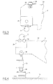
- FIG. 1 illustrates a crankshaft of a motor vehicle thermal motor.
- the crankshaft 2 comprises bearings 4 constituting axes of rotation resting on bearings of the motor housing.
- the crankshaft includes crank pins 5 connected to the crankshafts of the engine. He understands masses 6 connecting the bearings 4 and the crank pins 5 and allowing the crankshaft to spend idle times of engine operation through their inertia.
- the machine 8 according to the invention illustrated in particular in FIG. intended for the burnishing of the bearings 4 and the crank pins 5, roller burnishing comprising forming grooves 10 at the junction between the crank pins 5 or 4 and the masses 6.
- the machine comprises a wheel 12 rotated about an axis 14 parallel to a geometric axis 16 of the cylinder defining the crankpin 5 or the span 4.
- the machine comprises rollers 18 associated in pairs to the same wheel 12.
- Each wheel 18 is rotated about an axis 20 inclined by relative to axes 14 and 16 but extending in the plane defined jointly by them.
- the two knobs 18 are inclined in opposite directions to each other so that their axes form between them an angle of about 90 ° C.
- the machine comprises a member 20 arranged to exert a pressure on the wheel 12 towards the crankshaft, which pressure is transmitted to the mollettes 18 for the realization of the grooves 10 while the crankshaft is rotated about the axis 16.
- the machine comprises a reaction tool 22 arranged to generate an opposite reaction effort.
- FIG. 3 shows an arm 24 of the machine carrying a action tool 26 with the wheel 12 and the knobs 18.
- This tool 26 arranged in the lower part of the arm 24 is in contact with the crankshaft 2.
- the machine comprises at least one accelerometer 28 arranged in part upper arm 24.
- the accelerometer is fixed in being attached to the arm by means of a fixing screw 30. This accelerometer makes it possible to measure the appearance of vibrations in the arm.
- FIG. 4 illustrates the implantation of one of the force sensors 30 of the machine.
- another arm 24 of the machine also bearing roller tooling 26 in contact with the crankshaft 2.
- the machine comprises a clamping cylinder 32 of the roller arm. interposed between a lower end of this cylinder and a support 34 is a sensor 30.
- the jack 32 is supported by its upper end 36 on the arm 24 and its lower end 38 on the force sensor 30, itself supported by its base on the support 34.
- the efforts exercised by the wheels 18 on the crankshaft 2 are transmitted from this way up to the force sensor 30.
- each arm carrying tools comprises one or more accelerometers even cumulatively or alternatively one or more force sensors.
- the machine comprises a total of nine arms 24 in this example. Arms numbered with an odd number ensure the rolling of a respective bearing 4 while the arms numbered with an even number ensure the rolling of a respective crankpin 5. Arms associated with the bearings carry a force sensor 30 while the arms associated with the crank pins carry a vibration sensor 28.
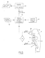
- the machine comprises means for collecting the signals from each of the sensors and process these signals for if necessary generate an alarm signaling abnormal operation.
- predetermined thresholds will have been recorded in the machine to detect that one or the other of the parameters measured by the sensors exceed one of these thresholds.
- setpoints can be entered into the machine and if necessary modified as shown in Box 49.
- the monitoring device of the machine will be provided, as shown in Box 50 in Figure 5, to detect the beginning of burnishing characterized by rotating the crankshaft or being informed thereof.
- the receipt of information on this start of operation allows trigger monitoring using the sensors.
- the informed device of the operation of the rollers compares the signals received by the sensors with setpoints.
- This treatment and monitoring can be carried out using a Movisys-type platform known in itself and will be briefly described below.
- the latter manages entrances and exits information and it controls the actuators of the machine. It is the interface with the external systems and receives information concerning example control of breakage or conveying parts. He communicates with the operator (s) in charge of the machine through a screen and push buttons.
- a man-machine interface is provided as illustrated in box 56. It includes a screen and push buttons. It informs the driver of the machine that a tool is broken and gives the case appropriate location. It validates the taking into account of information by the driver of the machine.
- the connections of the Movisys platform have been illustrated at Figure 6.
- the signals emanating from the force sensors are directed to a double resumption terminal block connected to a command control member 60 of the roller burnishing machine and returned to a bufferization module 62 of a Movisys 64 rack.
- the signals from the vibration sensors are directly sent in MSVU 66 units of rack 64.
- Other units MSVU are connected to the buffering module to receive signals from this last. All information from MSVU units is sent to the control unit via interface relays.
- the invention makes it possible to closely control the degradation of the tools of the machine using hardware and algorithms intended for the real-time predictive monitoring of rotating machines.
- the machine offers a reactive control mode. We can see in practical in most cases that the machine is stopped from the first piece made with degraded tools. All that is needed is to adapt the signal processing filtration algorithms most closely possible depending on the kinematics of the machine and tools monitored. Naturally, we will take care to determine the sensors as well as their implementation and signal filtering algorithms taking into account of the kinetics of the machine. Such a machine makes it possible to reduce very the number of non-compliant parts resulting from a degradation of burnishing tools.
Landscapes
- Engineering & Computer Science (AREA)
- Mechanical Engineering (AREA)
- Finish Polishing, Edge Sharpening, And Grinding By Specific Grinding Devices (AREA)
- Constituent Portions Of Griding Lathes, Driving, Sensing And Control (AREA)
Abstract
Description
- une accélération ; et
- une force.
- le capteur ou l'un des capteurs est fixé à un bras de la machine portant un outil destiné à être en contact avec le vilebrequin ;
- le capteur ou l'un des capteurs est fixé à une partie de la machine disposée pour fournir un effort de réaction à une action d'un outil de la machine sur le vilebrequin ;
- le capteur ou l'un des capteurs est fixé à une partie de la machine destinée à être opposée à un outil de la machine de part et d'autre du vilebrequin ;
- elle comprend au moins deux capteurs ;
- elle comprend au moins deux accéléromètres ;
- elle comprend au moins deux capteurs d'effort ;
- elle comprend des moyens pour détecter et signaler que le paramètre dépasse un seuil prédéterminé ; et
- elle comprend des moyens pour déclencher une alerte.
- une accélération ; et
- une force.
- la figure 1 est une vue partielle en élévation d'un vilebrequin destiné à être traité par la machine selon l'invention ;
- la figure 2 est une vue partielle illustrant le principe de fonctionnement de la machine de galetage selon l'invention ;
- les figures 3 et 4 sont deux vues partielles en élévation de la machine de la figure 2 montrant l'implantation de deux des capteurs ;
- la figure 5 est un synoptique de principe illustrant le traitement des signaux générés par les capteurs dans la machine de la figure 2 ; et
- la figure 6 est un synoptique de détail relatif à ce traitement des signaux.
Claims (10)
- Machine (8) de galetage de vilebrequins (2) de véhicule comprenant un capteur de mesure (28,30), caractérisée en ce que le capteur est apte à mesurer un paramètre choisi dans le groupe constitué par :une accélération ; etune force.
- Machine selon la revendication précédente, caractérisée en ce que le capteur (28,30) ou l'un des capteurs est fixé à un bras (24) de la machine portant un outil (18) destiné à être en contact avec le vilebrequin.
- Machine selon la revendication 1 ou 2, caractérisée en ce que le capteur (28,30) ou l'un des capteurs est fixé à une partie de la machine disposée pour fournir un effort de réaction à une action d'un outil de la machine sur le vilebrequin.
- Machine selon l'une quelconque des revendications précédentes, caractérisée en ce que le capteur (28,30) ou l'un des capteurs est fixé à une partie de la machine destinée à être opposée à un outil de la machine de part et d'autre du vilebrequin.
- Machine selon l'une quelconque des revendications précédentes, caractérisée en ce qu'elle comprend au moins deux capteurs (28,30).
- Machine selon l'une quelconque des revendications précédentes, caractérisée en ce qu'elle comprend au moins deux accéléromètres (28).
- Machine selon l'une quelconque des revendications précédentes, caractérisée en ce qu'elle comprend au moins deux capteurs d'effort (30).
- Machine selon l'une quelconque des revendications précédentes, caractérisée en ce qu'elle comprend des moyens (52,54,56) pour détecter et signaler que le paramètre dépasse un seuil prédéterminé.
- Machine selon l'une quelconque des revendications précédentes, caractérisée en ce qu'elle comprend des moyens (52,54,56) pour déclencher une alerte.
- Procédé de commande d'une machine (8) de galetage de vilebrequins (2) de véhicule, caractérisé en ce qu'on mesure un paramètre choisi dans le groupe constitué par :une accélération ; etune force.
Applications Claiming Priority (2)
| Application Number | Priority Date | Filing Date | Title |
|---|---|---|---|
| FR0402679A FR2867707B1 (fr) | 2004-03-16 | 2004-03-16 | Machine de galetage de vilebrequin de vehicule |
| FR0402679 | 2004-03-16 |
Publications (1)
| Publication Number | Publication Date |
|---|---|
| EP1577058A1 true EP1577058A1 (fr) | 2005-09-21 |
Family
ID=34834180
Family Applications (1)
| Application Number | Title | Priority Date | Filing Date |
|---|---|---|---|
| EP05300167A Withdrawn EP1577058A1 (fr) | 2004-03-16 | 2005-03-07 | Machine de galetage de vilebrequins de véhicule |
Country Status (2)
| Country | Link |
|---|---|
| EP (1) | EP1577058A1 (fr) |
| FR (1) | FR2867707B1 (fr) |
Citations (3)
| Publication number | Priority date | Publication date | Assignee | Title |
|---|---|---|---|---|
| US4559798A (en) * | 1984-07-09 | 1985-12-24 | Toyoda Koki Kabushiki Kaisha | Fillet rolling machine |
| DE3712651A1 (de) * | 1986-12-03 | 1988-06-16 | Iveco Fiat | Verfahren und vorrichtung zur kontrolle des zustands der rollen und gegenrollen waehrend des gleichzeitigen rollens mehrerer ringflaechen eines sich drehenden werkstuecks |
| EP1221355A2 (fr) * | 2000-12-04 | 2002-07-10 | Hegenscheidt-MFD GmbH & Co. KG | Machine d'écrouissage pour vilbrequins |
-
2004
- 2004-03-16 FR FR0402679A patent/FR2867707B1/fr not_active Expired - Fee Related
-
2005
- 2005-03-07 EP EP05300167A patent/EP1577058A1/fr not_active Withdrawn
Patent Citations (3)
| Publication number | Priority date | Publication date | Assignee | Title |
|---|---|---|---|---|
| US4559798A (en) * | 1984-07-09 | 1985-12-24 | Toyoda Koki Kabushiki Kaisha | Fillet rolling machine |
| DE3712651A1 (de) * | 1986-12-03 | 1988-06-16 | Iveco Fiat | Verfahren und vorrichtung zur kontrolle des zustands der rollen und gegenrollen waehrend des gleichzeitigen rollens mehrerer ringflaechen eines sich drehenden werkstuecks |
| EP1221355A2 (fr) * | 2000-12-04 | 2002-07-10 | Hegenscheidt-MFD GmbH & Co. KG | Machine d'écrouissage pour vilbrequins |
Also Published As
| Publication number | Publication date |
|---|---|
| FR2867707B1 (fr) | 2007-05-18 |
| FR2867707A1 (fr) | 2005-09-23 |
Similar Documents
| Publication | Publication Date | Title |
|---|---|---|
| EP2250460A2 (fr) | Systeme de mesure de jeux et d'affleurements et procede correspondant | |
| FR2553323A1 (fr) | Procede et machine pour le biseautage ou rainurage d'une lentille ophtalmique | |
| FR2832200A1 (fr) | Installation de traction d'un entrainement synchrone, notamment d'un moteur a combustion interne, munie d'un indicateur d'usure | |
| EP0543755B1 (fr) | Réducteur de vitesse du type cycloidal pour robots et autres manipulateurs industriels | |
| EP2760631B1 (fr) | Procede de detourage d'une lentille ophtalmique | |
| FR2844877A1 (fr) | Procede pour l'equilibrage rotatif d'un rotor de turbocompresseur avec machine electrique rotative | |
| FR3072172B1 (fr) | Procede de detection de defauts sur la denture d'une couronne entrainee en rotation au moyen d'un capteur sans contact | |
| FR2525138A1 (fr) | Appareil d'usinage de lentilles optiques | |
| FR2867707A1 (fr) | Machine de galetage de vilebrequin de vehicule | |
| EP0657727B1 (fr) | Dispositif et application pour l'équilibrage dynamique d'une pièce tournante en rotation | |
| WO1992009887A1 (fr) | Dispositif de detection des criques longitudinales sur des brames, notamment sur des brames d'acier | |
| EP0697591B1 (fr) | Dispositif pour l'inspection de la surface d'un cylindre de laminoir | |
| FR2676130A1 (fr) | Systeme de commande automatique du dephasage dans un appareil vibrant. | |
| FR2552003A1 (fr) | Procede et dispositif d'assemblage de joints a croisillon | |
| FR3033724A1 (fr) | Procede de reparation de la denture d'une couronne dentee | |
| FR2607920A1 (fr) | Procede et dispositif pour le controle de l'integrite des rouleaux et des contre-rouleaux employes pour le traitement simultane de moulage sur une pluralite de surfaces annulaires appartenant a un unique solide en rotation | |
| FR2494927A1 (fr) | Procede et dispositif pour detecter et regler le jeu axial de l'induit de moteurs electriques | |
| CA1326777C (fr) | Machine de reglage de pignons arbres sur outillage | |
| EP1193345A1 (fr) | Système de commande d'une machine de meulage | |
| FR2614227A1 (fr) | Meuleuse perfectionnee pour verres ophtalmiques. | |
| WO2023026003A1 (fr) | Dispositif de contrôle d'accès avec capteur gyroscopique | |
| FR2935799A1 (fr) | Procede et dispositif de mesure de balourd de vilebrequin | |
| FR2659436A1 (fr) | Dispositif de mesure de la configuration d'un verre de lunette, et appareil le comportant. | |
| FR3165683A1 (fr) | Procédé d’atténuation des perturbations de la mesure d’un angle d’inclinaison d’un véhicule | |
| FR3148555B3 (fr) | Dispositif permettant de protéger un capteur optique |
Legal Events
| Date | Code | Title | Description |
|---|---|---|---|
| PUAI | Public reference made under article 153(3) epc to a published international application that has entered the european phase |
Free format text: ORIGINAL CODE: 0009012 |
|
| AK | Designated contracting states |
Kind code of ref document: A1 Designated state(s): AT BE BG CH CY CZ DE DK EE ES FI FR GB GR HU IE IS IT LI LT LU MC NL PL PT RO SE SI SK TR |
|
| AX | Request for extension of the european patent |
Extension state: AL BA HR LV MK YU |
|
| 17P | Request for examination filed |
Effective date: 20060321 |
|
| AKX | Designation fees paid |
Designated state(s): AT BE BG CH CY CZ DE DK EE ES FI FR GB GR HU IE IS IT LI LT LU MC NL PL PT RO SE SI SK TR |
|
| 17Q | First examination report despatched |
Effective date: 20070118 |
|
| STAA | Information on the status of an ep patent application or granted ep patent |
Free format text: STATUS: THE APPLICATION IS DEEMED TO BE WITHDRAWN |
|
| 18D | Application deemed to be withdrawn |
Effective date: 20070530 |