EP1575690B1 - Dehydrating breather apparatus and method - Google Patents
Dehydrating breather apparatus and method Download PDFInfo
- Publication number
- EP1575690B1 EP1575690B1 EP03749416.8A EP03749416A EP1575690B1 EP 1575690 B1 EP1575690 B1 EP 1575690B1 EP 03749416 A EP03749416 A EP 03749416A EP 1575690 B1 EP1575690 B1 EP 1575690B1
- Authority
- EP
- European Patent Office
- Prior art keywords
- desiccant
- vessel
- valve housing
- breather apparatus
- vent assembly
- Prior art date
- Legal status (The legal status is an assumption and is not a legal conclusion. Google has not performed a legal analysis and makes no representation as to the accuracy of the status listed.)
- Expired - Lifetime
Links
- 238000000034 method Methods 0.000 title claims description 4
- 239000002274 desiccant Substances 0.000 claims description 62
- 230000007246 mechanism Effects 0.000 claims description 13
- 239000002245 particle Substances 0.000 claims description 13
- 229910000906 Bronze Inorganic materials 0.000 claims description 3
- 239000010974 bronze Substances 0.000 claims description 3
- KUNSUQLRTQLHQQ-UHFFFAOYSA-N copper tin Chemical compound [Cu].[Sn] KUNSUQLRTQLHQQ-UHFFFAOYSA-N 0.000 claims description 3
- 238000007667 floating Methods 0.000 claims description 3
- 239000011152 fibreglass Substances 0.000 claims description 2
- 230000001105 regulatory effect Effects 0.000 claims description 2
- 230000001276 controlling effect Effects 0.000 claims 1
- 239000000463 material Substances 0.000 description 6
- 230000002452 interceptive effect Effects 0.000 description 3
- XLYOFNOQVPJJNP-UHFFFAOYSA-N water Substances O XLYOFNOQVPJJNP-UHFFFAOYSA-N 0.000 description 3
- 238000009833 condensation Methods 0.000 description 2
- 230000005494 condensation Effects 0.000 description 2
- 230000007423 decrease Effects 0.000 description 2
- 238000001035 drying Methods 0.000 description 2
- 229920003023 plastic Polymers 0.000 description 2
- VYPSYNLAJGMNEJ-UHFFFAOYSA-N Silicium dioxide Chemical compound O=[Si]=O VYPSYNLAJGMNEJ-UHFFFAOYSA-N 0.000 description 1
- 239000004020 conductor Substances 0.000 description 1
- 238000010276 construction Methods 0.000 description 1
- 230000001419 dependent effect Effects 0.000 description 1
- 238000005516 engineering process Methods 0.000 description 1
- 239000011521 glass Substances 0.000 description 1
- 239000007788 liquid Substances 0.000 description 1
- 239000004033 plastic Substances 0.000 description 1
- 239000004417 polycarbonate Substances 0.000 description 1
- 229920000515 polycarbonate Polymers 0.000 description 1
- 239000000741 silica gel Substances 0.000 description 1
- 229910002027 silica gel Inorganic materials 0.000 description 1
- 229910001220 stainless steel Inorganic materials 0.000 description 1
- 239000010935 stainless steel Substances 0.000 description 1
- 239000000126 substance Substances 0.000 description 1
Images


Classifications
-
- B—PERFORMING OPERATIONS; TRANSPORTING
- B01—PHYSICAL OR CHEMICAL PROCESSES OR APPARATUS IN GENERAL
- B01D—SEPARATION
- B01D53/00—Separation of gases or vapours; Recovering vapours of volatile solvents from gases; Chemical or biological purification of waste gases, e.g. engine exhaust gases, smoke, fumes, flue gases, aerosols
- B01D53/26—Drying gases or vapours
- B01D53/261—Drying gases or vapours by adsorption
-
- B—PERFORMING OPERATIONS; TRANSPORTING
- B01—PHYSICAL OR CHEMICAL PROCESSES OR APPARATUS IN GENERAL
- B01D—SEPARATION
- B01D53/00—Separation of gases or vapours; Recovering vapours of volatile solvents from gases; Chemical or biological purification of waste gases, e.g. engine exhaust gases, smoke, fumes, flue gases, aerosols
- B01D53/02—Separation of gases or vapours; Recovering vapours of volatile solvents from gases; Chemical or biological purification of waste gases, e.g. engine exhaust gases, smoke, fumes, flue gases, aerosols by adsorption, e.g. preparative gas chromatography
- B01D53/04—Separation of gases or vapours; Recovering vapours of volatile solvents from gases; Chemical or biological purification of waste gases, e.g. engine exhaust gases, smoke, fumes, flue gases, aerosols by adsorption, e.g. preparative gas chromatography with stationary adsorbents
- B01D53/0407—Constructional details of adsorbing systems
-
- B—PERFORMING OPERATIONS; TRANSPORTING
- B01—PHYSICAL OR CHEMICAL PROCESSES OR APPARATUS IN GENERAL
- B01D—SEPARATION
- B01D2253/00—Adsorbents used in seperation treatment of gases and vapours
- B01D2253/25—Coated, impregnated or composite adsorbents
-
- B—PERFORMING OPERATIONS; TRANSPORTING
- B01—PHYSICAL OR CHEMICAL PROCESSES OR APPARATUS IN GENERAL
- B01D—SEPARATION
- B01D2257/00—Components to be removed
- B01D2257/80—Water
-
- B—PERFORMING OPERATIONS; TRANSPORTING
- B01—PHYSICAL OR CHEMICAL PROCESSES OR APPARATUS IN GENERAL
- B01D—SEPARATION
- B01D53/00—Separation of gases or vapours; Recovering vapours of volatile solvents from gases; Chemical or biological purification of waste gases, e.g. engine exhaust gases, smoke, fumes, flue gases, aerosols
- B01D53/02—Separation of gases or vapours; Recovering vapours of volatile solvents from gases; Chemical or biological purification of waste gases, e.g. engine exhaust gases, smoke, fumes, flue gases, aerosols by adsorption, e.g. preparative gas chromatography
- B01D53/04—Separation of gases or vapours; Recovering vapours of volatile solvents from gases; Chemical or biological purification of waste gases, e.g. engine exhaust gases, smoke, fumes, flue gases, aerosols by adsorption, e.g. preparative gas chromatography with stationary adsorbents
- B01D53/0454—Controlling adsorption
-
- H—ELECTRICITY
- H01—ELECTRIC ELEMENTS
- H01F—MAGNETS; INDUCTANCES; TRANSFORMERS; SELECTION OF MATERIALS FOR THEIR MAGNETIC PROPERTIES
- H01F27/00—Details of transformers or inductances, in general
- H01F27/08—Cooling; Ventilating
- H01F27/10—Liquid cooling
- H01F27/12—Oil cooling
- H01F27/14—Expansion chambers; Oil conservators; Gas cushions; Arrangements for purifying, drying, or filling
-
- Y—GENERAL TAGGING OF NEW TECHNOLOGICAL DEVELOPMENTS; GENERAL TAGGING OF CROSS-SECTIONAL TECHNOLOGIES SPANNING OVER SEVERAL SECTIONS OF THE IPC; TECHNICAL SUBJECTS COVERED BY FORMER USPC CROSS-REFERENCE ART COLLECTIONS [XRACs] AND DIGESTS
- Y10—TECHNICAL SUBJECTS COVERED BY FORMER USPC
- Y10T—TECHNICAL SUBJECTS COVERED BY FORMER US CLASSIFICATION
- Y10T137/00—Fluid handling
- Y10T137/794—With means for separating solid material from the fluid
- Y10T137/7976—Plural separating elements
Definitions
- This invention pertains generally to dehydrators for removing moisture from air. More particularly, the present invention is directed to a dehydrating breather apparatus for power devices.
- Such a dehydrating breather apparatus is known from prior art document US 5,902,381 A .
- Dehydrating apparatuses of different designs are further known from US 5,427,609 A , US 3,572,008 A and US 2,083,732 A .
- High power electrical equipment such as large electrical transformers, load tap changers, and circuit breakers, are typically immersed in oil, which is utilized to insulate and cool the power devices. Because the oil expands and contracts with temperature changes, such equipment is provided with a head space above the oil that is vented to the atmosphere to control pressure in, for example, a transformer tank. The pressure in the tank has to be maintained such that air bubbles, which can decrease the dielectric strength of the oil, are inhibited from developing in the oil.
- a dehydrator breather is conventionally utilized to regulate airflow into and out of the tank.
- a vent is provided between the vessel and the outside air.
- a valve is positioned between the vent and dehydrator breather container that controls the pressure in the tank by opening and closing, as necessary, to control air flow into and out of the tank.
- the dehydrator breather includes a desiccant material, such as a silica gel, to remove any moisture from the air before it is allowed into the tank.
- a desiccant material such as a silica gel
- the desiccant escapes the desiccant container.
- the desiccant may break into fine pieces that escape the desiccant container.
- desiccant particles may pass through the valve with air that is exiting the dehydrator breather, and become trapped in the valve and/or trapped on top of the vent.
- moisture which evaporates from the drying of the desiccant, often forms condensation on the walls of the dehydrator breather.
- the condensation returns to a liquid state, it flows through the valve and out to the atmosphere via the holes in the vent.
- the desiccant particles are trapped in the valve or clogging the vent, the moisture may become trapped in the vessel and the desiccant may be unable to dry out completely. As a result, the dehydrating breather will not be able to perform its drying functions.
- the object of the invention is achieved with a dehydrating breather apparatus and a method of operating a dehydrator breather apparatus in accordance with one of the independent claims.
- Advantageous embodiments are specified in the dependent claims.
- a dehydrator breather in one aspect of the present invention, includes a vessel, a valve housing coupled to the vessel, and a vent assembly coupled to the valve housing.
- the vent assembly includes a vent assembly body, and at least one screened port. The screened port is disposed along a vertical axis of the vent assembly body.
- a method for operating a dehydrator breather includes regulating air through the dehydrator breather utilizing a valve housing, removing moisture from the air utilizing a desiccant, retaining the desiccant in a desiccant container and capturing any desiccant that passes through the desiccant container utilizing a vent assembly.
- the vent assembly includes a vent body, and at least one screened port positioned on a surface of the vent body.
- a dehydrating breather in yet another aspect of the present invention, includes a vessel, a valve housing coupled to the vessel.
- the valve housing includes a valve seat formed integrally with the valve housing.
- the dehydrating breather 10 includes a vessel 12 that, in an exemplary embodiment of the present invention, is formed of a glass or a transparent plastic, such as polycarbonate.
- the vessel 12 is cylindrical in shape.
- a container 14 is mounted within the interior of the vessel 12 and is utilized to contain desiccant.
- a heater 15 is positioned within the desiccant container 14, and is utilized to drive moisture from the desiccant.
- mounting mechanisms 16,18 for example, threaded screws and locking devices 20,22, such as bolts, secure the heater 15 to the desiccant container 14.
- the desiccant container 14 is made from a screen material providing openings in the desiccant container 14.
- the desiccant is coated with an indicating substance that causes the color of the desiccant to change according to the degree of moisture that it is retaining.
- the openings in the desiccant container 14 allow the desiccant to be viewed from outside of the desiccant container 14, and thus, allow the condition of the desiccant to be ascertained.
- the openings in the desiccant container 14 also allow moisture to escape the desiccant container.
- valve housing 24 Coupled to the bottom of the vessel 12 is a valve housing 24.
- the valve housing 24 includes a floating ball 26.
- the ball 26 fits within the valve housing 24 and controls air flow into and out of the vessel 12, according to a differential in air pressure between the vessel 12 and, for example, a transformer tank 27.
- the ball 26 moves upward, so that air can be expelled from the head space 29, through the vessel 12, and out of the housing 24.
- the ball 26 moves upward to allow air to flow into the housing 24 and/or vent assembly 34, through the vessel 12, and into the head space 29 of the transformer tank 27.
- the ball 26 blocks the admission of air into the vessel 12 to prevent unnecessary admittance of air, which may be moisture-laden, into the dehydrator breather 10 and transformer tank 27.
- a seal 28 for example, a gasket, is provided between the vessel 12 and the housing 24 to prevent moisture from entering the dehydrator breather 10 at the location where the vessel 12 meets the housing 24.
- the mounting mechanisms 16,18 and locking mechanisms 30,32 are utilized to secure the housing 24 to the vessel 12.
- a vent assembly includes sintered bronze vents.
- the vent assembly 34 for example a muffler, is coupled to the valve housing 24.
- the muffler 34 of the present invention improves the operation of the breather because the sintered bronze vents have fine openings that may trap dessicant particles that escape the dessicant container 14.
- the muffler 34 and the valve housing 24, in an exemplary embodiment of the present invention have threaded portions, such that the muffler 34 is threadably attached to the valve housing 24, and can be.easily unscrewed from the valve housing 24.
- the muffler 34 has openings, for example, vertically disposed ports 36-42.
- the ports 36-42 are covered with screen material 44-50.
- the screened ports 36-42 allow air to flow into and out of the vessel 12.
- the screened ports 36-42 also serve to filter particles from the air being drawn into the muffler 34. It should be understood that the number of screens utilized to fully cover the ports 36-42 may vary.
- the vent assembly 34 may also be utilized to capture any desiccant particles that may escape the desiccant container 14 and pass through the valve housing 24.
- the screen ports 36-42 are disposed along a vertical axis of the vent assembly 34. Thus, if any desiccant particles happen to block one of the screened ports, for example, screened port 36, a screen port positioned above the blocked screen port, such as screened port 38, will still allow air to enter and exit the valve housing 24.
- vent assembly 34 When the vent assembly 34 no longer has the ability to accommodate any additional desiccant particles, the vent assembly 34 can be unscrewed from the valve housing 24, so that the desiccant particles can be emptied. In addition, the vent assembly 34 allows any water that passes through the valve housing to escape through the screened openings. Accordingly, the design of a dehydrator breather in accordance with the present invention prevents desiccant particles from interfering with the flow of air into and out of the valve housing 24.
- the body/vent housing of the vent assembly 34 is made from a plastic material.
- the vent assembly is a high flow muffler, manufactured by Adsens Technology of City of Industry, CA.
- a filter 52 is positioned within the vessel 12.
- the filter 52 is made from a fiberglass paper.
- supports 54,56 are utilized to secure the filter 52 within the vessel 12.
- the mounting mechanisms 16, 18, are utilized to secure the filter 52 and support screens 54,56 within the vessel.
- Securing mechanisms, such as bolts 58-64, are utilized to secure the supports 54,56 to the filter 52.
- the filter 52 prevents desiccant particulate that escapes the desiccant container 14 from entering the valve housing 24.
- the filter 52 prevents loose desiccant particulate from plugging the valve housing 24.
- moisture which seeks to exit the vessel 12 through the valve housing 24 is prevented from accumulating in the valve housing, and not allowing the desiccant to dry.
- a cap 66 is provided to seal the desiccant container.
- Mounting mechanisms 68, 70 and locking mechanisms 72,74 are utilized to secure the cap 66 to the vessel 12 via the heater 15.
- a connector 73 is provided for connecting the breather 10 to, for example, an auxiliary electrical box to control operations of the heater 15.
- a port 75 is provided for connecting the dehydrator breather 10 to, for example, the air head space 29 of the transformer tank 27.
- FIG. 2 Shown in FIG. 2 is a filter support 76 and filter 78 in accordance with the present invention. Ports 80 and 82 may be provided in the filter support 76 that align with ports 84,86 of the filter 78.
- the filter 78 and filter support 76 are cylindrical in shape.
- the filter support 76 is made from a screen material.
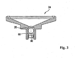
- FIG. 3 Shown in FIG. 3 is a cross-sectional view of a valve housing 24 in accordance with the present invention. As shown in FIG. 3 , a valve 88 is formed with the valve housing 24. In an exemplary embodiment of the present invention, the valve 88 is a floating ball valve where a ball 26 is positioned at valve seat 90.
- the dehydrator breather 10 of the present invention prevents desiccant particulate from interfering with airflow into and out of the dehydrating breather.
- the dehydrating breather of the present invention prevents desiccant particles from interfering with the flow of water, which may accumulate within the vessel 12, out of the dehydrator breather 10.
Landscapes
- Chemical & Material Sciences (AREA)
- Engineering & Computer Science (AREA)
- Analytical Chemistry (AREA)
- General Chemical & Material Sciences (AREA)
- Oil, Petroleum & Natural Gas (AREA)
- Chemical Kinetics & Catalysis (AREA)
- Drying Of Gases (AREA)
- Self-Closing Valves And Venting Or Aerating Valves (AREA)
- Separation Of Gases By Adsorption (AREA)
- Filtering Of Dispersed Particles In Gases (AREA)
Description
- This invention pertains generally to dehydrators for removing moisture from air. More particularly, the present invention is directed to a dehydrating breather apparatus for power devices.
- Such a dehydrating breather apparatus is known from prior art document
US 5,902,381 A . Dehydrating apparatuses of different designs are further known fromUS 5,427,609 A ,US 3,572,008 A andUS 2,083,732 A . - High power electrical equipment, such as large electrical transformers, load tap changers, and circuit breakers, are typically immersed in oil, which is utilized to insulate and cool the power devices. Because the oil expands and contracts with temperature changes, such equipment is provided with a head space above the oil that is vented to the atmosphere to control pressure in, for example, a transformer tank. The pressure in the tank has to be maintained such that air bubbles, which can decrease the dielectric strength of the oil, are inhibited from developing in the oil.
- When the heat in the tank increases, the oil in the tank expands, the pressure in the tank increases, and air in the reservoir is forced from the tank. When the tank begins to cool down, the oil in the tank contracts, the pressure in the tank decreases, and air is drawn into the tank to maintain the pressure in the tank.
- A dehydrator breather is conventionally utilized to regulate airflow into and out of the tank. In some dehydrating breathers, a vent is provided between the vessel and the outside air. A valve is positioned between the vent and dehydrator breather container that controls the pressure in the tank by opening and closing, as necessary, to control air flow into and out of the tank.
- Often, the dehydrator breather includes a desiccant material, such as a silica gel, to remove any moisture from the air before it is allowed into the tank. Water is a conductor, and thus, moisture entering the tank has the capability of destroying the electrical properties of the transformer.
- Problems arise, however, when the desiccant escapes the desiccant container. For example, during shipment, the desiccant may break into fine pieces that escape the desiccant container. In addition, desiccant particles may pass through the valve with air that is exiting the dehydrator breather, and become trapped in the valve and/or trapped on top of the vent.
- Further, moisture, which evaporates from the drying of the desiccant, often forms condensation on the walls of the dehydrator breather. When the condensation returns to a liquid state, it flows through the valve and out to the atmosphere via the holes in the vent. However, if the desiccant particles are trapped in the valve or clogging the vent, the moisture may become trapped in the vessel and the desiccant may be unable to dry out completely. As a result, the dehydrating breather will not be able to perform its drying functions.
- Accordingly, it would be desirable to provide a dehydrator breather that does not allow desiccant particles, which may escape the desiccant container, from disturbing the operation of the dehydrator.
- The object of the invention is achieved with a dehydrating breather apparatus and a method of operating a dehydrator breather apparatus in accordance with one of the independent claims. Advantageous embodiments are specified in the dependent claims.
- In one aspect of the present invention, a dehydrator breather is provided that includes a vessel, a valve housing coupled to the vessel, and a vent assembly coupled to the valve housing. The vent assembly includes a vent assembly body, and at least one screened port. The screened port is disposed along a vertical axis of the vent assembly body.
- In another aspect of the present invention, a method for operating a dehydrator breather is provided that includes regulating air through the dehydrator breather utilizing a valve housing, removing moisture from the air utilizing a desiccant, retaining the desiccant in a desiccant container and capturing any desiccant that passes through the desiccant container utilizing a vent assembly. The vent assembly includes a vent body, and at least one screened port positioned on a surface of the vent body.
- In yet another aspect of the present invention, a dehydrating breather is provided that includes a vessel, a valve housing coupled to the vessel. The valve housing includes a valve seat formed integrally with the valve housing.
- There has thus been outlined, rather broadly, the more important features of the invention in order that the detailed description thereof that follows may be better understood, and in order that the present contribution to the art may be better appreciated. There are, of course, additional features of the invention that will be described below and which will form the subject matter of the claims appended hereto.
- In this respect, before explaining at least one embodiment of the invention in detail, it is to be understood that the invention is not limited in its application to the details of construction and to the arrangements of the components set forth in the following description or illustrated in the drawings. Also, it is to be understood that the phraseology and terminology employed herein, as well as the abstract, are for the purpose of description and should not be regarded as limiting.
-
-
FIG. 1 is an exploded view of a dehydrating breather in accordance with the present invention. -
FIG. 2 is a front elevation view of a filter and filter support in accordance with the present invention. -
FIG. 3 is a cross-sectional view of a valve housing in accordance with the present invention. - Referring now to
FIG. 1 of the figures, wherein like reference numerals indicate like elements, there is shown inFIG. 1 adehydrating breather 10 in accordance with the present invention. As shown inFIG. 1 , thedehydrating breather 10, includes avessel 12 that, in an exemplary embodiment of the present invention, is formed of a glass or a transparent plastic, such as polycarbonate. In an exemplary embodiment of the present invention, as shown inFIG. 1 , thevessel 12 is cylindrical in shape. - A
container 14 is mounted within the interior of thevessel 12 and is utilized to contain desiccant. Aheater 15 is positioned within thedesiccant container 14, and is utilized to drive moisture from the desiccant. In an exemplary embodiment of the present invention,mounting mechanisms locking devices heater 15 to thedesiccant container 14. - In an exemplary embodiment of the present invention, the
desiccant container 14 is made from a screen material providing openings in thedesiccant container 14. In the same or another exemplary embodiment of the present invention, the desiccant is coated with an indicating substance that causes the color of the desiccant to change according to the degree of moisture that it is retaining. The openings in thedesiccant container 14 allow the desiccant to be viewed from outside of thedesiccant container 14, and thus, allow the condition of the desiccant to be ascertained. The openings in thedesiccant container 14 also allow moisture to escape the desiccant container. - Coupled to the bottom of the
vessel 12 is avalve housing 24. In an exemplary embodiment of the present invention, thevalve housing 24 includes afloating ball 26. Theball 26 fits within thevalve housing 24 and controls air flow into and out of thevessel 12, according to a differential in air pressure between thevessel 12 and, for example, atransformer tank 27. - For example, when the
oil 29 expands within atransformer tank 27, air in ahead space 29 is forced from thetransformer tank 27 and into thevessel 12. Accordingly, the air pressure in thetransformer tank 27 is greater than the air pressure in thevessel 12. Theball 26 is sufficiently light, such that it moves up, so air can flow from thevessel 12 through thehousing 24. - When the air pressure inside of the
vessel 12 is greater than the air pressure inside thetransformer tank 27, theball 26 moves upward, so that air can be expelled from thehead space 29, through thevessel 12, and out of thehousing 24. When the air pressure inside of thevessel 12 is greater than the air pressure inside thetransformer tank 27, theball 26 moves upward to allow air to flow into thehousing 24 and/orvent assembly 34, through thevessel 12, and into thehead space 29 of thetransformer tank 27. When there is no pressure differential between, for example, thetransformer tank 27 and the interior of thevessel 12, theball 26 blocks the admission of air into thevessel 12 to prevent unnecessary admittance of air, which may be moisture-laden, into the dehydrator breather 10 andtransformer tank 27. - In an exemplary embodiment of the present invention, a
seal 28, for example, a gasket, is provided between thevessel 12 and thehousing 24 to prevent moisture from entering thedehydrator breather 10 at the location where thevessel 12 meets thehousing 24. In an exemplary embodiment of the present invention, themounting mechanisms locking mechanisms housing 24 to thevessel 12. - In an exemplary embodiment of the present invention, a vent assembly includes sintered bronze vents. In another exemplary embodiment of the present invention, the
vent assembly 34, for example a muffler, is coupled to thevalve housing 24. Themuffler 34 of the present invention improves the operation of the breather because the sintered bronze vents have fine openings that may trap dessicant particles that escape thedessicant container 14. Themuffler 34 and thevalve housing 24, in an exemplary embodiment of the present invention, have threaded portions, such that themuffler 34 is threadably attached to thevalve housing 24, and can be.easily unscrewed from thevalve housing 24. - In the same or another exemplary embodiment of the present invention, the
muffler 34 has openings, for example, vertically disposed ports 36-42. In an exemplary embodiment of the present invention, the ports 36-42 are covered with screen material 44-50. The screened ports 36-42 allow air to flow into and out of thevessel 12. The screened ports 36-42 also serve to filter particles from the air being drawn into themuffler 34. It should be understood that the number of screens utilized to fully cover the ports 36-42 may vary. - The
vent assembly 34 may also be utilized to capture any desiccant particles that may escape thedesiccant container 14 and pass through thevalve housing 24. In an exemplary embodiment of the present invention, the screen ports 36-42 are disposed along a vertical axis of thevent assembly 34. Thus, if any desiccant particles happen to block one of the screened ports, for example, screenedport 36, a screen port positioned above the blocked screen port, such as screenedport 38, will still allow air to enter and exit thevalve housing 24. - When the
vent assembly 34 no longer has the ability to accommodate any additional desiccant particles, thevent assembly 34 can be unscrewed from thevalve housing 24, so that the desiccant particles can be emptied. In addition, thevent assembly 34 allows any water that passes through the valve housing to escape through the screened openings. Accordingly, the design of a dehydrator breather in accordance with the present invention prevents desiccant particles from interfering with the flow of air into and out of thevalve housing 24. - In an exemplary embodiment of the present invention, fifty mesh stainless steel screen material is utilized for ports 36-42. In an exemplary embodiment of the present invention, the body/vent housing of the
vent assembly 34 is made from a plastic material. In an exemplary embodiment of the present invention, the vent assembly is a high flow muffler, manufactured by Adsens Technology of City of Industry, CA. - In an exemplary embodiment of the present invention, a
filter 52 is positioned within thevessel 12. In an exemplary embodiment of the present invention, thefilter 52 is made from a fiberglass paper. In the same or another exemplary embodiment of the present invention, supports 54,56 are utilized to secure thefilter 52 within thevessel 12. In an exemplary embodiment of the present invention, the mountingmechanisms filter 52 and support screens 54,56 within the vessel. Securing mechanisms, such as bolts 58-64, are utilized to secure thesupports filter 52. - The
filter 52 prevents desiccant particulate that escapes thedesiccant container 14 from entering thevalve housing 24. Thus, thefilter 52 prevents loose desiccant particulate from plugging thevalve housing 24. In addition, moisture which seeks to exit thevessel 12 through thevalve housing 24 is prevented from accumulating in the valve housing, and not allowing the desiccant to dry. - A
cap 66 is provided to seal the desiccant container. Mountingmechanisms mechanisms cap 66 to thevessel 12 via theheater 15. Aconnector 73 is provided for connecting thebreather 10 to, for example, an auxiliary electrical box to control operations of theheater 15. Aport 75 is provided for connecting thedehydrator breather 10 to, for example, theair head space 29 of thetransformer tank 27. - Shown in
FIG. 2 is afilter support 76 andfilter 78 in accordance with the present invention.Ports filter support 76 that align withports filter 78. In an exemplary embodiment of the present invention, thefilter 78 andfilter support 76 are cylindrical in shape. In the same or another exemplary embodiment of the present invention, thefilter support 76 is made from a screen material. - Shown in
FIG. 3 is a cross-sectional view of avalve housing 24 in accordance with the present invention. As shown inFIG. 3 , avalve 88 is formed with thevalve housing 24. In an exemplary embodiment of the present invention, thevalve 88 is a floating ball valve where aball 26 is positioned atvalve seat 90. - The
dehydrator breather 10 of the present invention prevents desiccant particulate from interfering with airflow into and out of the dehydrating breather. In addition, the dehydrating breather of the present invention prevents desiccant particles from interfering with the flow of water, which may accumulate within thevessel 12, out of thedehydrator breather 10.
Claims (11)
- A dehydrating breather apparatus (10), comprising:a vessel (12), wherein a desiccant container (14), including a cap (66) to seal the desiccant container (14) and the cap (66) comprising a port (75) to connect to a transformer tank (27), wherein the cap (66) is secured to the vessel (12) via a heater (15) using mounting mechanisms (68, 70) and locking mechanisms (72, 74), wherein the desiccant container (14) is utilized to contain desiccant, wherein the desiccant container (14) is mounted within the interior of said vessel (12) and the heater (15) in the desiccant container (14) is utilized to drive moisture from the desiccant; and wherein the heater (15) is positioned within the desiccant container (14) and the heater (15) is secured to the desiccant container (14) using mounting mechanisms (16, 18) and locking mechanisms (20, 22), the apparatus (10) further comprising a connector (73) for controlling operations of the heater (15), and;a valve housing (24) coupled to the bottom of the vessel (12), wherein said valve housing (24) is coupled to the vessel (12) and is secured to the vessel (12) by mounting mechanisms (16, 18) and locking mechanisms (30, 32); andfurther comprising a vent assembly (34), wherein said vent assembly (34) is coupled to the valve housing (24) and comprising:a vent assembly body; andat least one screened port (36-42), wherein said screened port (36-42) is disposed along a vertical axis of the vent assembly body.
- The dehydrating breather apparatus (10) of claim 1,
characterized in that
the at least one screened port (36-42) is a plurality of screen ports (36-42) aligned along a vertical axis of the vent assembly body, thus, if any particles of the desiccant happen to block one of the screen ports (36-42) a screen port positioned above the blocked screen port will still allow air to enter and exit the valve housing (24). - The dehydrating breather apparatus (10) of claim 1,
characterized in that
the vent assembly (34) has threaded portions and the valve assembly (24) is threadably coupled to the vent assembly (34). - The dehydrating breather apparatus (10) of claim 1,
characterized in that
a seal (28) is provided between the vessel (12) and the valve housing (24). - The dehydrating breather apparatus (10) of claim 1,
characterized in that
the valve housing (24) includes a floating ball (26), which fits within the valve housing (24) and controls air flow into and out of the vessel (12) according to a differential in air pressure between the vessel (12) and the transformer tank (27). - The dehydrating breather apparatus (10) of claim 1,
characterized by
further comprising a filter (52), wherein said filter (52) is positioned within the vessel and which prevents desiccant particulate that escapes the desiccant container (14) from entering the valve housing (24). - The dehydrating breather apparatus (10) of claim 6,
characterized in that
the filter is made from a fiberglass paper. - The dehydrating breather apparatus (10), of claim 6,
characterized by
further comprising supports (54, 56) that are utilized to secure the filter (52) within the vessel (12). - A method of operating a dehydrator breather apparatus (10) according to one of the preceding claims 1 to 5, comprising:regulating air through the dehydrator breather apparatus (10) utilising the valve housing (24);removing moisture from the air utilising the desiccant;retaining the desiccant in the desiccant container (14); andcapturing any desiccant that passes through the desiccant container (14) with the at least one screened port (36-42) positioned on a surface of the vent assembly body.
- The dehydrating breather apparatus (10), of claim 1,
characterized in
the said vent assembly (34) is a muffler. - The dehydrating breather apparatus (10) of claim 10,
characterized in that
said screened port (36-42) includes sintered bronze vents have fine openings that may trap desiccant particles that escape the desiccant container (14).
Applications Claiming Priority (3)
| Application Number | Priority Date | Filing Date | Title |
|---|---|---|---|
| US235795 | 2002-09-06 | ||
| US10/235,795 US6797037B2 (en) | 2002-09-06 | 2002-09-06 | Dehydrating breather apparatus and method |
| PCT/US2003/027731 WO2004022204A1 (en) | 2002-09-06 | 2003-09-05 | Dehydrating breather apparatus and method |
Publications (3)
| Publication Number | Publication Date |
|---|---|
| EP1575690A1 EP1575690A1 (en) | 2005-09-21 |
| EP1575690A4 EP1575690A4 (en) | 2007-02-28 |
| EP1575690B1 true EP1575690B1 (en) | 2015-11-04 |
Family
ID=31977579
Family Applications (1)
| Application Number | Title | Priority Date | Filing Date |
|---|---|---|---|
| EP03749416.8A Expired - Lifetime EP1575690B1 (en) | 2002-09-06 | 2003-09-05 | Dehydrating breather apparatus and method |
Country Status (9)
| Country | Link |
|---|---|
| US (3) | US6797037B2 (en) |
| EP (1) | EP1575690B1 (en) |
| CN (1) | CN100381194C (en) |
| AU (1) | AU2003268451A1 (en) |
| BR (1) | BR0314467B1 (en) |
| CA (1) | CA2497852C (en) |
| HU (1) | HUE026678T2 (en) |
| MX (1) | MXPA05002502A (en) |
| WO (1) | WO2004022204A1 (en) |
Families Citing this family (22)
| Publication number | Priority date | Publication date | Assignee | Title |
|---|---|---|---|---|
| US6846454B2 (en) * | 2001-12-24 | 2005-01-25 | Agilent Technologies, Inc. | Fluid exit in reaction chambers |
| US6797037B2 (en) * | 2002-09-06 | 2004-09-28 | Waukesha Electric Systems, Incorporated | Dehydrating breather apparatus and method |
| US7332015B2 (en) * | 2002-09-06 | 2008-02-19 | Waukesha Electric Systems, Inc | Automatic dehydrating breather apparatus and method |
| US7410529B2 (en) * | 2004-10-05 | 2008-08-12 | Caterpillar Inc. | Filter service system and method |
| US7384455B2 (en) * | 2004-10-05 | 2008-06-10 | Caterpillar Inc. | Filter service system and method |
| US7419532B2 (en) * | 2004-10-05 | 2008-09-02 | Caterpillar Inc. | Deposition system and method |
| US7462222B2 (en) * | 2004-10-05 | 2008-12-09 | Caterpillar Inc. | Filter service system |
| US7566358B2 (en) * | 2005-10-05 | 2009-07-28 | Veeder-Root Company | Fuel storage tank pressure management system and method employing a carbon canister |
| KR101111476B1 (en) * | 2006-12-21 | 2012-02-22 | 더 프록터 앤드 갬블 캄파니 | Dispensing measurement device and method of measuring dispensing |
| US8499788B2 (en) * | 2008-06-03 | 2013-08-06 | Richard J. RAYMO, SR. | Dry air fuel vent breather |
| CN101496982B (en) * | 2009-01-16 | 2012-04-18 | 尹智鸿 | Dehumidifiers and dehumidification systems |
| CN102350092B (en) * | 2011-07-27 | 2013-08-14 | 许盛英 | Dehydrating apparatus for alcoholic group bactericidal and fresh keeping liquid |
| USD698653S1 (en) | 2012-10-01 | 2014-02-04 | Daniel R. Schumaier | Desiccant container |
| US9114353B2 (en) | 2012-12-18 | 2015-08-25 | Waukesha Electric Systems, Inc. | Dehumidifier and breather configured for operation during regeneration |
| US8871005B2 (en) * | 2012-12-31 | 2014-10-28 | Qualitrol Company, Llc | Methods of regenerating desiccant in a breathing apparatus |
| CN104036926A (en) * | 2014-07-01 | 2014-09-10 | 国家电网公司 | Main transformation respirator with online regeneration function and use method |
| CN105674725A (en) * | 2016-04-01 | 2016-06-15 | 安庆市德创机电产品设计有限公司 | Drying maintaining assembly for electric control device of back flush filter |
| CN107342156A (en) * | 2017-07-04 | 2017-11-10 | 广东电网有限责任公司惠州供电局 | A kind of Novel main transformer body respirator apparatus |
| CN107240483B (en) * | 2017-07-31 | 2023-06-02 | 国网新疆电力公司巴州供电公司 | transformer respirator |
| US10427081B1 (en) * | 2017-08-11 | 2019-10-01 | Newman IP LLC | Drum vent filter with pressure indicator/stop assembly |
| DE112019004535A5 (en) * | 2018-09-11 | 2021-06-02 | Mann+Hummel Gmbh | DRYING SYSTEM, DRYER CARTRIDGE AND USE OF A DRYER CARTRIDGE |
| CN111540566A (en) * | 2020-05-13 | 2020-08-14 | 蔡金明 | Oil leakage prevention transformer |
Family Cites Families (26)
| Publication number | Priority date | Publication date | Assignee | Title |
|---|---|---|---|---|
| US2083732A (en) * | 1932-11-22 | 1937-06-15 | Pittsburgh Res Corp | Adsorbent apparatus |
| US2505581A (en) * | 1945-03-26 | 1950-04-25 | Gen Electric | Means for drying gas in electrical apparatus |
| US2669320A (en) * | 1949-08-26 | 1954-02-16 | Paul B Shaw | Water separator and filter for air pressure lines |
| GB1199941A (en) | 1967-04-19 | 1970-07-22 | Grace W R & Co | A Gas Breather Assembly |
| US3572008A (en) * | 1968-10-25 | 1971-03-23 | Hankison Corp | Methods and means for cleaning and drying compressed fluid systems |
| US3731678A (en) * | 1971-03-05 | 1973-05-08 | Phyllis Pyzel | Smoke inhalation protector |
| US3815752A (en) * | 1972-03-02 | 1974-06-11 | Sporlan Valve Co | Refrigerant filter-drier |
| US4127395A (en) | 1976-10-18 | 1978-11-28 | Pall Corporation | Adsorbent fractionator with fail-safe automatic cycle control and process |
| US4322223A (en) | 1979-03-30 | 1982-03-30 | Pall Corporation | Adsorbent fractionators with electronic sequence timer cycle control and process |
| IT1121117B (en) | 1979-06-06 | 1986-03-26 | Lattuada Sergio | METHOD TO AUTOMATE AND OPTIMIZE THE OPERATING CYCLE OF ADSORPTION DEHYDRATION PLANTS |
| CA1158991A (en) * | 1980-05-02 | 1983-12-20 | Barton A. Gravatt | Adsorbent fractionator with automatic cycle control and process |
| JPS579319U (en) * | 1980-06-14 | 1982-01-18 | ||
| US4543446A (en) * | 1981-02-09 | 1985-09-24 | General Electric Company | Vaporization-cooled transformer havig provisions for replenishment of molecular sieve material |
| US4546442A (en) | 1982-11-24 | 1985-10-08 | Pall Corporation | Microcomputer control system for desiccant dryer |
| US4504286A (en) | 1984-04-25 | 1985-03-12 | Phillips Petroleum Company | Automatic drying tower switching system |
| JPS61174707A (en) * | 1985-01-30 | 1986-08-06 | Toshiba Corp | Gas insulation transformer |
| US4677929A (en) * | 1986-02-28 | 1987-07-07 | Harris William B | Desiccant cartridge for fuel tank vent line |
| US5427609A (en) * | 1993-09-14 | 1995-06-27 | Horton Industries, Inc. | Device for cleaning and drying compressed gas |
| US6235192B1 (en) * | 1997-03-20 | 2001-05-22 | Parker-Hannifin Corporation | Biflow drier with improved filtration |
| US5902381A (en) * | 1997-05-30 | 1999-05-11 | General Signal Corporation | Dehydrating breather apparatus |
| US6071321A (en) * | 1997-11-26 | 2000-06-06 | Westinghouse Air Brake Company | E-1 air dryer liquid separator with baffle |
| DE20104259U1 (en) | 2001-03-01 | 2001-06-07 | Siemens AG, 80333 München | Dehumidifier for oil-insulated transformers or inductors |
| EP1313112B1 (en) * | 2001-11-13 | 2004-03-17 | Messko Albert Hauser GmbH & Co. KG | Air dehumidifier for oil insulated transformers, choke coils as well as tap changers |
| US6835235B2 (en) * | 2002-01-25 | 2004-12-28 | Sporlan Valve Company | Molded core filter drier with filter media molded to core for use in heat pump systems |
| US6797037B2 (en) * | 2002-09-06 | 2004-09-28 | Waukesha Electric Systems, Incorporated | Dehydrating breather apparatus and method |
| DE10315719B3 (en) * | 2003-04-04 | 2004-12-23 | Maschinenfabrik Reinhausen Gmbh | Dehumidifier for oil-insulated transformers, choke coils and tap changers |
-
2002
- 2002-09-06 US US10/235,795 patent/US6797037B2/en not_active Expired - Lifetime
-
2003
- 2003-09-05 EP EP03749416.8A patent/EP1575690B1/en not_active Expired - Lifetime
- 2003-09-05 BR BR0314467A patent/BR0314467B1/en not_active IP Right Cessation
- 2003-09-05 WO PCT/US2003/027731 patent/WO2004022204A1/en not_active Ceased
- 2003-09-05 AU AU2003268451A patent/AU2003268451A1/en not_active Abandoned
- 2003-09-05 CA CA 2497852 patent/CA2497852C/en not_active Expired - Lifetime
- 2003-09-05 HU HUE03749416A patent/HUE026678T2/en unknown
- 2003-09-05 CN CNB038211629A patent/CN100381194C/en not_active Expired - Fee Related
- 2003-09-05 MX MXPA05002502A patent/MXPA05002502A/en active IP Right Grant
-
2004
- 2004-07-23 US US10/896,989 patent/US7285150B2/en not_active Expired - Lifetime
-
2010
- 2010-02-19 US US12/708,730 patent/USRE42058E1/en not_active Expired - Lifetime
Also Published As
| Publication number | Publication date |
|---|---|
| MXPA05002502A (en) | 2005-11-17 |
| CN100381194C (en) | 2008-04-16 |
| CA2497852C (en) | 2011-03-22 |
| USRE42058E1 (en) | 2011-01-25 |
| US6797037B2 (en) | 2004-09-28 |
| WO2004022204A1 (en) | 2004-03-18 |
| WO2004022204A9 (en) | 2004-04-29 |
| AU2003268451A1 (en) | 2004-03-29 |
| US7285150B2 (en) | 2007-10-23 |
| US20040045435A1 (en) | 2004-03-11 |
| EP1575690A4 (en) | 2007-02-28 |
| HUE026678T2 (en) | 2016-06-28 |
| US20050000356A1 (en) | 2005-01-06 |
| CA2497852A1 (en) | 2004-03-18 |
| EP1575690A1 (en) | 2005-09-21 |
| BR0314467A (en) | 2005-08-16 |
| CN1681575A (en) | 2005-10-12 |
| BR0314467B1 (en) | 2013-09-10 |
Similar Documents
| Publication | Publication Date | Title |
|---|---|---|
| CA2497852C (en) | Dehydrating breather apparatus and method | |
| CA2593528C (en) | Automatic dehydrating breather apparatus and method | |
| ES3063093T3 (en) | Two-phase immersion cooling apparatus with active vapor management | |
| KR101917660B1 (en) | Connection board for solar power generation | |
| US7563310B2 (en) | Air dehumidifier for oil-insulated transformers, choke coils and steps switches | |
| US5665146A (en) | Dehumidifier | |
| US20160184773A1 (en) | Dehumidifier and Breather Configured for Operation During Regeneration | |
| KR101928990B1 (en) | Air breather device | |
| KR102025705B1 (en) | Power transformer with improved drying function and suppression of dielectric breakdown | |
| US20070107647A1 (en) | Dehumidifying radome vent | |
| JP2003229680A (en) | Electronic equipment housing equipment for outdoor installation | |
| HK1112528B (en) | Automatic dehydrating breather apparatus and dehydrating system | |
| WO2022239044A1 (en) | Filtering device for a self-regenerating breather device | |
| HK1091026B (en) | Air de-humidifier for oil-insulated transformers, choke coils and step switches | |
| JPH06101862A (en) | Drainage device for dehumidified water generated by dehumidification | |
| MXPA97005852A (en) | Oil recovery device with base deevaporador and filter mounted in the cabe | |
| JPS61141912A (en) | Draining apparatus |
Legal Events
| Date | Code | Title | Description |
|---|---|---|---|
| PUAI | Public reference made under article 153(3) epc to a published international application that has entered the european phase |
Free format text: ORIGINAL CODE: 0009012 |
|
| 17P | Request for examination filed |
Effective date: 20050308 |
|
| AK | Designated contracting states |
Kind code of ref document: A1 Designated state(s): AT BE BG CH CY CZ DE DK EE ES FI FR GB GR HU IE IT LI LU MC NL PT RO SE SI SK TR |
|
| AX | Request for extension of the european patent |
Extension state: AL LT LV MK |
|
| DAX | Request for extension of the european patent (deleted) | ||
| A4 | Supplementary search report drawn up and despatched |
Effective date: 20070126 |
|
| 17Q | First examination report despatched |
Effective date: 20090223 |
|
| GRAP | Despatch of communication of intention to grant a patent |
Free format text: ORIGINAL CODE: EPIDOSNIGR1 |
|
| INTG | Intention to grant announced |
Effective date: 20150629 |
|
| GRAS | Grant fee paid |
Free format text: ORIGINAL CODE: EPIDOSNIGR3 |
|
| GRAA | (expected) grant |
Free format text: ORIGINAL CODE: 0009210 |
|
| AK | Designated contracting states |
Kind code of ref document: B1 Designated state(s): AT BE BG CH CY CZ DE DK EE ES FI FR GB GR HU IE IT LI LU MC NL PT RO SE SI SK TR |
|
| REG | Reference to a national code |
Ref country code: GB Ref legal event code: FG4D |
|
| REG | Reference to a national code |
Ref country code: CH Ref legal event code: EP |
|
| REG | Reference to a national code |
Ref country code: AT Ref legal event code: REF Ref document number: 758806 Country of ref document: AT Kind code of ref document: T Effective date: 20151115 |
|
| REG | Reference to a national code |
Ref country code: IE Ref legal event code: FG4D |
|
| REG | Reference to a national code |
Ref country code: DE Ref legal event code: R096 Ref document number: 60348215 Country of ref document: DE |
|
| REG | Reference to a national code |
Ref country code: NL Ref legal event code: MP Effective date: 20151104 |
|
| REG | Reference to a national code |
Ref country code: AT Ref legal event code: MK05 Ref document number: 758806 Country of ref document: AT Kind code of ref document: T Effective date: 20151104 |
|
| PG25 | Lapsed in a contracting state [announced via postgrant information from national office to epo] |
Ref country code: IT Free format text: LAPSE BECAUSE OF FAILURE TO SUBMIT A TRANSLATION OF THE DESCRIPTION OR TO PAY THE FEE WITHIN THE PRESCRIBED TIME-LIMIT Effective date: 20151104 Ref country code: ES Free format text: LAPSE BECAUSE OF FAILURE TO SUBMIT A TRANSLATION OF THE DESCRIPTION OR TO PAY THE FEE WITHIN THE PRESCRIBED TIME-LIMIT Effective date: 20151104 Ref country code: NL Free format text: LAPSE BECAUSE OF FAILURE TO SUBMIT A TRANSLATION OF THE DESCRIPTION OR TO PAY THE FEE WITHIN THE PRESCRIBED TIME-LIMIT Effective date: 20151104 |
|
| PG25 | Lapsed in a contracting state [announced via postgrant information from national office to epo] |
Ref country code: PT Free format text: LAPSE BECAUSE OF FAILURE TO SUBMIT A TRANSLATION OF THE DESCRIPTION OR TO PAY THE FEE WITHIN THE PRESCRIBED TIME-LIMIT Effective date: 20160304 Ref country code: AT Free format text: LAPSE BECAUSE OF FAILURE TO SUBMIT A TRANSLATION OF THE DESCRIPTION OR TO PAY THE FEE WITHIN THE PRESCRIBED TIME-LIMIT Effective date: 20151104 Ref country code: FI Free format text: LAPSE BECAUSE OF FAILURE TO SUBMIT A TRANSLATION OF THE DESCRIPTION OR TO PAY THE FEE WITHIN THE PRESCRIBED TIME-LIMIT Effective date: 20151104 Ref country code: GR Free format text: LAPSE BECAUSE OF FAILURE TO SUBMIT A TRANSLATION OF THE DESCRIPTION OR TO PAY THE FEE WITHIN THE PRESCRIBED TIME-LIMIT Effective date: 20160205 Ref country code: SE Free format text: LAPSE BECAUSE OF FAILURE TO SUBMIT A TRANSLATION OF THE DESCRIPTION OR TO PAY THE FEE WITHIN THE PRESCRIBED TIME-LIMIT Effective date: 20151104 |
|
| REG | Reference to a national code |
Ref country code: HU Ref legal event code: AG4A Ref document number: E026678 Country of ref document: HU |
|
| REG | Reference to a national code |
Ref country code: DE Ref legal event code: R097 Ref document number: 60348215 Country of ref document: DE |
|
| PG25 | Lapsed in a contracting state [announced via postgrant information from national office to epo] |
Ref country code: SK Free format text: LAPSE BECAUSE OF FAILURE TO SUBMIT A TRANSLATION OF THE DESCRIPTION OR TO PAY THE FEE WITHIN THE PRESCRIBED TIME-LIMIT Effective date: 20151104 Ref country code: DK Free format text: LAPSE BECAUSE OF FAILURE TO SUBMIT A TRANSLATION OF THE DESCRIPTION OR TO PAY THE FEE WITHIN THE PRESCRIBED TIME-LIMIT Effective date: 20151104 Ref country code: EE Free format text: LAPSE BECAUSE OF FAILURE TO SUBMIT A TRANSLATION OF THE DESCRIPTION OR TO PAY THE FEE WITHIN THE PRESCRIBED TIME-LIMIT Effective date: 20151104 Ref country code: RO Free format text: LAPSE BECAUSE OF FAILURE TO SUBMIT A TRANSLATION OF THE DESCRIPTION OR TO PAY THE FEE WITHIN THE PRESCRIBED TIME-LIMIT Effective date: 20151104 |
|
| PLBE | No opposition filed within time limit |
Free format text: ORIGINAL CODE: 0009261 |
|
| STAA | Information on the status of an ep patent application or granted ep patent |
Free format text: STATUS: NO OPPOSITION FILED WITHIN TIME LIMIT |
|
| 26N | No opposition filed |
Effective date: 20160805 |
|
| PG25 | Lapsed in a contracting state [announced via postgrant information from national office to epo] |
Ref country code: SI Free format text: LAPSE BECAUSE OF FAILURE TO SUBMIT A TRANSLATION OF THE DESCRIPTION OR TO PAY THE FEE WITHIN THE PRESCRIBED TIME-LIMIT Effective date: 20151104 |
|
| PG25 | Lapsed in a contracting state [announced via postgrant information from national office to epo] |
Ref country code: BE Free format text: LAPSE BECAUSE OF FAILURE TO SUBMIT A TRANSLATION OF THE DESCRIPTION OR TO PAY THE FEE WITHIN THE PRESCRIBED TIME-LIMIT Effective date: 20151104 |
|
| PG25 | Lapsed in a contracting state [announced via postgrant information from national office to epo] |
Ref country code: MC Free format text: LAPSE BECAUSE OF FAILURE TO SUBMIT A TRANSLATION OF THE DESCRIPTION OR TO PAY THE FEE WITHIN THE PRESCRIBED TIME-LIMIT Effective date: 20151104 |
|
| REG | Reference to a national code |
Ref country code: CH Ref legal event code: PL |
|
| GBPC | Gb: european patent ceased through non-payment of renewal fee |
Effective date: 20160905 |
|
| REG | Reference to a national code |
Ref country code: IE Ref legal event code: MM4A |
|
| REG | Reference to a national code |
Ref country code: FR Ref legal event code: ST Effective date: 20170531 |
|
| PG25 | Lapsed in a contracting state [announced via postgrant information from national office to epo] |
Ref country code: IE Free format text: LAPSE BECAUSE OF NON-PAYMENT OF DUE FEES Effective date: 20160905 Ref country code: FR Free format text: LAPSE BECAUSE OF NON-PAYMENT OF DUE FEES Effective date: 20160930 Ref country code: LI Free format text: LAPSE BECAUSE OF NON-PAYMENT OF DUE FEES Effective date: 20160930 Ref country code: GB Free format text: LAPSE BECAUSE OF NON-PAYMENT OF DUE FEES Effective date: 20160905 Ref country code: CH Free format text: LAPSE BECAUSE OF NON-PAYMENT OF DUE FEES Effective date: 20160930 |
|
| PG25 | Lapsed in a contracting state [announced via postgrant information from national office to epo] |
Ref country code: LU Free format text: LAPSE BECAUSE OF NON-PAYMENT OF DUE FEES Effective date: 20160905 |
|
| PG25 | Lapsed in a contracting state [announced via postgrant information from national office to epo] |
Ref country code: CY Free format text: LAPSE BECAUSE OF FAILURE TO SUBMIT A TRANSLATION OF THE DESCRIPTION OR TO PAY THE FEE WITHIN THE PRESCRIBED TIME-LIMIT Effective date: 20151104 |
|
| PG25 | Lapsed in a contracting state [announced via postgrant information from national office to epo] |
Ref country code: TR Free format text: LAPSE BECAUSE OF FAILURE TO SUBMIT A TRANSLATION OF THE DESCRIPTION OR TO PAY THE FEE WITHIN THE PRESCRIBED TIME-LIMIT Effective date: 20151104 |
|
| PG25 | Lapsed in a contracting state [announced via postgrant information from national office to epo] |
Ref country code: BG Free format text: LAPSE BECAUSE OF FAILURE TO SUBMIT A TRANSLATION OF THE DESCRIPTION OR TO PAY THE FEE WITHIN THE PRESCRIBED TIME-LIMIT Effective date: 20151104 |
|
| PGFP | Annual fee paid to national office [announced via postgrant information from national office to epo] |
Ref country code: DE Payment date: 20180927 Year of fee payment: 16 |
|
| PGFP | Annual fee paid to national office [announced via postgrant information from national office to epo] |
Ref country code: CZ Payment date: 20180829 Year of fee payment: 16 Ref country code: HU Payment date: 20180828 Year of fee payment: 16 |
|
| REG | Reference to a national code |
Ref country code: DE Ref legal event code: R119 Ref document number: 60348215 Country of ref document: DE |
|
| PG25 | Lapsed in a contracting state [announced via postgrant information from national office to epo] |
Ref country code: CZ Free format text: LAPSE BECAUSE OF NON-PAYMENT OF DUE FEES Effective date: 20190905 |
|
| PG25 | Lapsed in a contracting state [announced via postgrant information from national office to epo] |
Ref country code: DE Free format text: LAPSE BECAUSE OF NON-PAYMENT OF DUE FEES Effective date: 20200401 |
|
| PG25 | Lapsed in a contracting state [announced via postgrant information from national office to epo] |
Ref country code: HU Free format text: LAPSE BECAUSE OF NON-PAYMENT OF DUE FEES Effective date: 20190906 |