EP1575445B1 - Device for dispensing a mixed multi-component compound - Google Patents
Device for dispensing a mixed multi-component compound Download PDFInfo
- Publication number
- EP1575445B1 EP1575445B1 EP03810844A EP03810844A EP1575445B1 EP 1575445 B1 EP1575445 B1 EP 1575445B1 EP 03810844 A EP03810844 A EP 03810844A EP 03810844 A EP03810844 A EP 03810844A EP 1575445 B1 EP1575445 B1 EP 1575445B1
- Authority
- EP
- European Patent Office
- Prior art keywords
- mixing nozzle
- cartridge
- holder
- mixing
- designed
- Prior art date
- Legal status (The legal status is an assumption and is not a legal conclusion. Google has not performed a legal analysis and makes no representation as to the accuracy of the status listed.)
- Expired - Lifetime
Links
- 150000001875 compounds Chemical class 0.000 title claims abstract description 5
- 238000006073 displacement reaction Methods 0.000 claims 1
- 230000037431 insertion Effects 0.000 description 4
- 238000003780 insertion Methods 0.000 description 4
- 239000000463 material Substances 0.000 description 3
- 239000007788 liquid Substances 0.000 description 2
- 239000005548 dental material Substances 0.000 description 1
- 230000000994 depressogenic effect Effects 0.000 description 1
- 230000009191 jumping Effects 0.000 description 1
- 238000004519 manufacturing process Methods 0.000 description 1
- 238000004806 packaging method and process Methods 0.000 description 1
- 239000002699 waste material Substances 0.000 description 1
- 238000004383 yellowing Methods 0.000 description 1
Images

Classifications
-
- A—HUMAN NECESSITIES
- A61—MEDICAL OR VETERINARY SCIENCE; HYGIENE
- A61C—DENTISTRY; APPARATUS OR METHODS FOR ORAL OR DENTAL HYGIENE
- A61C5/00—Filling or capping teeth
- A61C5/60—Devices specially adapted for pressing or mixing capping or filling materials, e.g. amalgam presses
- A61C5/62—Applicators, e.g. syringes or guns
- A61C5/64—Applicators, e.g. syringes or guns for multi-component compositions
-
- B—PERFORMING OPERATIONS; TRANSPORTING
- B01—PHYSICAL OR CHEMICAL PROCESSES OR APPARATUS IN GENERAL
- B01F—MIXING, e.g. DISSOLVING, EMULSIFYING OR DISPERSING
- B01F27/00—Mixers with rotary stirring devices in fixed receptacles; Kneaders
- B01F27/05—Stirrers
- B01F27/11—Stirrers characterised by the configuration of the stirrers
- B01F27/112—Stirrers characterised by the configuration of the stirrers with arms, paddles, vanes or blades
- B01F27/1125—Stirrers characterised by the configuration of the stirrers with arms, paddles, vanes or blades with vanes or blades extending parallel or oblique to the stirrer axis
-
- A—HUMAN NECESSITIES
- A61—MEDICAL OR VETERINARY SCIENCE; HYGIENE
- A61C—DENTISTRY; APPARATUS OR METHODS FOR ORAL OR DENTAL HYGIENE
- A61C9/00—Impression cups, i.e. impression trays; Impression methods
- A61C9/0026—Syringes or guns for injecting impression material; Mixing impression material for immediate use
-
- B—PERFORMING OPERATIONS; TRANSPORTING
- B01—PHYSICAL OR CHEMICAL PROCESSES OR APPARATUS IN GENERAL
- B01F—MIXING, e.g. DISSOLVING, EMULSIFYING OR DISPERSING
- B01F2101/00—Mixing characterised by the nature of the mixed materials or by the application field
- B01F2101/2305—Mixers of the two-component package type, i.e. where at least two components are separately stored, and are mixed in the moment of application
-
- B—PERFORMING OPERATIONS; TRANSPORTING
- B01—PHYSICAL OR CHEMICAL PROCESSES OR APPARATUS IN GENERAL
- B01F—MIXING, e.g. DISSOLVING, EMULSIFYING OR DISPERSING
- B01F27/00—Mixers with rotary stirring devices in fixed receptacles; Kneaders
- B01F27/05—Stirrers
- B01F27/09—Stirrers characterised by the mounting of the stirrers with respect to the receptacle
- B01F27/092—Stirrers characterised by the mounting of the stirrers with respect to the receptacle occupying substantially the whole interior space of the receptacle
Definitions
- the invention relates to a device for dispensing a mixed multicomponent compound, in particular for dental purposes, according to the preamble of claim 1.
- the cartridge consists of a piston-cylinder unit to which, inter alia, a so-called in the document cartridge front part 17 is attached.
- This cartridge front part, to which the mixing nozzle is attached, is not a holder for the cartridge and can not replace such a holder. Such a fixture will probably be necessary if the cartridge is to be used.
- dental impressions For the production of dental impressions, higher-viscosity dental materials are used. These are prepared by mixing a plurality of components, in particular two components, which are stored in multiple cartridges, in particular double cartridges. For mixing and dispensing the masses, a mixer is required. Further, a device is required which provides for the advancement of the pistons in the cartridges for dispensing the masses. The outlet of the mixer then dispenses the mixed material advantageously on a spoon, which is used for impression taking.
- a cartridge contains material for several applications. Since the material begins to cure immediately after mixing, a new mixer should be used for each application. For this purpose, the cartridge must either be removed from the device to attach the new mixer, or the mixer must be plugged with the cartridge in the device, which is cumbersome, since the cartridge opening is poorly visible through their head. Another disadvantage is that for each cartridge additional disposable parts (slide) are necessary, which increases the cost and creates additional waste.
- the object is to provide a device of the type mentioned, in which the mixing nozzle can be replaced in a simpler way and faster.
- the solution according to the invention is that the holder for the mixing nozzle for insertion and removal of the mixing nozzle is formed transversely to the longitudinal direction of the device and connected via an axial parallel guide with the holder for the cartridge and in the longitudinal direction of the device in a substantially tight connection with the Containers and is movable away from this again.
- the invention also includes those embodiments in which the mixing nozzle can not be replaced until the cartridge has been removed.
- the mixing nozzle can be inserted and removed transversely to the longitudinal axis of the device.
- the Auspreß act in the longitudinal direction, so that the mixing nozzle can not be pushed out of the device by these forces.
- the invention is particularly advantageous to use in conjunction with dynamic mixers.
- the device according to the invention has an Arithmetic which is provided with the mixing nozzle designed as a dynamic mixer.
- the holder for the mixing nozzle can be moved in the longitudinal direction of the device, that is to say it can be moved toward the outlet channels and optionally the drive shaft for the dynamic mixer.
- the drive of the dynamic mixer and pressing of the components can then be done with the same device.
- the device has a stop for. Limitation of the transverse movement of the mixing nozzle. Thanks to its transversal direction, it is inserted as far as the stop. The operator is then certain that the mixing nozzle is now in the correct position to be associated with the cartridge.
- the mixing nozzle can be particularly fast, easy and reliable attached to the cartridge or be solved by the same, if the holder for the mixing nozzle is adjustable by means of a lever.
- the mixing nozzle has inlet ports for the components which must be angularly aligned with the exit channels of the components from the containers of the cartridge.
- the holder for the mixing nozzle has two projections, on which the foot of the mixing nozzle is pushed with diametrically arranged grooves therein.
- the projections can have different thicknesses and the grooves corresponding widths, so that the mixer is not rotated by 180 ° axially, so can be inserted only in one position. This is particularly advantageous if the outlet channels and corresponding to the inlet openings have different diameters.
- cartridges and mixing nozzles of the actual device are detachable parts, the invention should also include a device having a cartridge and a mixing nozzle.
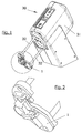
- FIG. 1 is a device 30 according to the invention with a main and drive part 31, with which the pistons can be driven, and a base plate 1 shown.
- the Base plate of the FIG. 1 is in FIG. 2 shown on an enlarged scale.
- the cartridges are clamped between the main part 31 of the device and the base plate 1.
- the base plate 1 is held by rods 32.
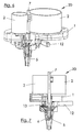
- the Fig. 3, 4 . 6 and 7 show a detailed view of the device according to the invention.
- the cartridge 20 is placed with their containers 2. Only the lower part of the container 2 is shown, which one must think upwards continued.
- a piston (not shown) is arranged in each case, which can be depressed by means also not shown above the container 2 devices, so that the components exit through outlet tubes 3 and can enter into inlet openings 4 of a mixing nozzle 5, then from this to be pushed out.
- the mixing nozzle 5 in this case has a rotatably driven by a shaft 7 mixing roller 6.
- the mixing nozzle 5 is, as in Fig. 5 is shown, provided at two diametrically opposite locations of its foot part 8 with mutually parallel grooves 9, of which in Fig. 5 only one is shown. With these grooves 9, the mixing nozzle 5 is guided on two rails 10 of the device when the mixing nozzle 5 is inserted into the device. This insertion in the transverse direction is limited by a stop 11.
- the rails 10, which hold the mixing nozzle 5, are now by means of a lever 12, which is mounted at 13 on a corresponding projection of the base 1, upwardly movable.
- the lever 12 is also pivotally connected to the movable part, which contains the rails 10. These rails are in turn through Parallel guides held in the axial direction, which are indicated at 14.
- the lever 12 is moved upward, so that, as in the 6 and 7 is shown, the mixing nozzle 5 is connected with its openings 4 with the outlet tubes 3 of the components and is reliably held there. At the same time, the mixing roller 6 comes into contact with the shaft 7 and can therefore be driven by the shaft 7.
- the lever 12 is moved downward, and the mixing nozzle 5 is pulled out laterally.
- the insertion and removal prepares because of the guide through the grooves 9 and rails 10 and due to the fact no problems that the corresponding area of the device is clearly visible.
- the lateral insertion and removal in the transverse direction is also not hindered by the exit tubes 3 and the shaft 7. These parts only come into reliable contact with the corresponding parts of the mixing nozzle 5 when the lever 12 and thus also the mixing nozzle 5 are moved upwards in the direction of the cartridge with its containers 2.
Abstract
Description
Die Erfindung betrifft eine Vorrichtung zum Ausgeben einer gemischten Mehrkomponentenmasse, insbesondere für zahnärztliche Zwecke gemäß dem Oberbegriff von Anspruch 1.The invention relates to a device for dispensing a mixed multicomponent compound, in particular for dental purposes, according to the preamble of
Es sind zwar Vorrichtungen zum Ausgeben einer gemischten Mehrkomponentenmasse mit einer Kartusche mit mehreren, die Komponenten enthaltenen Behältern bekannt, auf die die Mischdüse direkt aufgesetzt wird (
Es ist weiter eine Mehrkomponentenkartusche mit einer auswechselbaren Innenverpackung bekannt, die ausdrücklich für Flüssigkeiten bestimmt ist (
Zur Herstellung von Zahnabdrücken werden höher viskose Dentalmassen verwendet. Diese werden durch Mischen mehrerer Komponenten, insbesondere von zwei Komponenten, hergestellt, die in Mehrfachkartuschen, insbesondere Doppelkartuschen, gelagert werden. Für das Mischen und Ausbringen der Massen ist ein Mischer erforderlich. Weiter ist eine Vorrichtung erforderlich, welche für den Vorschub der Kolben in den Kartuschen zum Ausgeben der Massen sorgt. Die Auslaßöffnung des Mischers spendet dann das gemischte Material vorteilhaft auf einen Löffel, der zur Abdrucknahme dient.For the production of dental impressions, higher-viscosity dental materials are used. These are prepared by mixing a plurality of components, in particular two components, which are stored in multiple cartridges, in particular double cartridges. For mixing and dispensing the masses, a mixer is required. Further, a device is required which provides for the advancement of the pistons in the cartridges for dispensing the masses. The outlet of the mixer then dispenses the mixed material advantageously on a spoon, which is used for impression taking.
Die Kartuschen werden zu diesem Zweck mit der Auslaßöffnung nach unten in das Ausbringgerät eingelegt. Um ein Abspringen des Mischers während des Betriebs zu vermeiden, wird die Mischdüse an der Kartusche arretiert. Hierzu kann der Mischer über einen an der Kartusche schwenkbar anzubringenden Bügel gehalten werden oder über einen Schieber an den Auslaßöffnungen der Kartusche gehalten werden (
Es ist eine tragbare und von Hand zu betätigende Vorrichtung zum Ausgelben von gemischten Mehrkomponentenmassen bekannt, bei der die Mischdüse in Längsrichtung der Vorlleistung aufgesteckt und durch eine Überwurfmutter befestigt wird (
Die Aufgabe besteht in der Schaffung einer Vorrichtung der eingangs genannten Art, bei der die Mischdüse auf einfachere Weise und schneller ausgewechselt werden kann.The object is to provide a device of the type mentioned, in which the mixing nozzle can be replaced in a simpler way and faster.
Die erfindungsgemäße Lösung besteht darin, dass die Halterung für die Mischdüse zum Einsetzen und Herausnehmen der Mischdüse quer zur Längsrichtung der Vorrichtung ausgebildet ist und über eine axiale Parallelführung mit der Halterung für die Kartusche verbunden und in Längsrichtung der Vorrichtung in eine im wesentlichen dichte Verbindung mit den Behältern und von dieser wieder weg bewegbar ist.The solution according to the invention is that the holder for the mixing nozzle for insertion and removal of the mixing nozzle is formed transversely to the longitudinal direction of the device and connected via an axial parallel guide with the holder for the cartridge and in the longitudinal direction of the device in a substantially tight connection with the Containers and is movable away from this again.
Es ist also die Mischdüse nicht direkt mit der Kartusche verbunden. Beide werden vielmehr separat in der Vorrichtung untergebracht und gehalten. Mit der Halterung für die Mischdüse kann diese mit der Kartusche in Verbindung gebracht werden, was insbesondere bedeutet, daß eine im wesentlichen dichte Verbindung zwischen den Austrittskanälen der Komponenten aus den Behältern und den Eintrittsöffnungen der Mischdüse erreicht wird. Die Mischdüse wird durch diese Halterung an der Vorrichtung gehalten, an der auch die Kartusche bereits gehalten wird. Die Mischdüse kann dabei durch entsprechende Betätigung ihrer Halterung eingesetzt oder entfernt werden, ohne daß die Kartusche entfernt werden muß. Wegwerfteile in Form von Schiebern wie beim Stand der Technik sind nicht mehr erforderlich.So it is not the mixing nozzle directly connected to the cartridge. Both are rather separate in the device housed and kept. With the holder for the mixing nozzle, this can be associated with the cartridge, which means in particular that a substantially tight connection between the outlet channels of the components from the containers and the inlet openings of the mixing nozzle is achieved. The mixing nozzle is held by this holder on the device on which the cartridge is already held. The mixing nozzle can do this be inserted or removed by appropriate operation of their holder, without the cartridge must be removed. Disposable parts in the form of sliders as in the prior art are no longer required.
Obwohl dieses letzere Merkmal besonders vorteilhaft ist, gehören zur Erfindung auch solche Ausführüngsformen, bei denen die Mischdüse erst ausgewechselt werden kann, wenn vorher die Kartusche entfernt ist.Although this latter feature is particularly advantageous, the invention also includes those embodiments in which the mixing nozzle can not be replaced until the cartridge has been removed.
Die Mischdüse ist quer zur Längsachse der Vorrichtung einsetzbar und herausnehmbar. Die Auspreßkräfte wirken dabei in Längsrichtung, so daß die Mischdüse durch diese Kräfte nicht aus der Vorrichtung herausgedrückt werden kann.The mixing nozzle can be inserted and removed transversely to the longitudinal axis of the device. The Auspreßkräfte act in the longitudinal direction, so that the mixing nozzle can not be pushed out of the device by these forces.
Die Erfindung ist besonders vorteilhaft im Zusammenhang mit dynamischen Mischern anzuwenden. In diesem Falle ist zweckmäßigerweise vorgesehen, daß die erfindungsgemäße Vorrichtung einen mit der als dynamischer Mischer ausgebildeten Mischdüse verbihdbären Aritrieb aufweist.The invention is particularly advantageous to use in conjunction with dynamic mixers. In this case, it is expediently provided that the device according to the invention has an Arithmetic which is provided with the mixing nozzle designed as a dynamic mixer.
Die Halterung für die Mischdüse ist in Längsrichtung der Vorrichtung bewegbar, also auf die Austrittskanäle und gegebenenfalls die Antriebswelle für den dynamischen Mischer hin bewegbar.The holder for the mixing nozzle can be moved in the longitudinal direction of the device, that is to say it can be moved toward the outlet channels and optionally the drive shaft for the dynamic mixer.
Der Antrieb des dynamischen Mischers und Auspressen der Komponenten kann dann mit derselben Vorrichtung erfolgen.The drive of the dynamic mixer and pressing of the components can then be done with the same device.
Zweckmäßigerweise weist die Vorrichtung einen Anschlag zur. Begrenzung der Querbewegung der Mischdüse auf. Diese wird dank in Querrichtung bis zum Anschlag eingeschoben. Die Bedienungsperson ist dann sicher, daß sich die Mischdüse nunmehr in der richtigen Stellung befindet, in der sie mit der Kartusche in Verbindung gebracht werden kann.Conveniently, the device has a stop for. Limitation of the transverse movement of the mixing nozzle. Thanks to its transversal direction, it is inserted as far as the stop. The operator is then certain that the mixing nozzle is now in the correct position to be associated with the cartridge.
Die Mischdüse kann besonders schnell, einfach und zuverlässig an der Kartusche befestigt, bzw. von derselben gelöst werden, wenn die Halterung für die Mischdüse mit Hilfe eines Hebels verstellbar ist.The mixing nozzle can be particularly fast, easy and reliable attached to the cartridge or be solved by the same, if the holder for the mixing nozzle is adjustable by means of a lever.
Die Mischdüse besitzt Einlaßöffnungen für die Komponenten, die winkelmäßig mit den Austrittskanälen der Komponenten aus den Behältern der Kartusche ausgerichtet werden müssen. Dies geschieht bei einer vorteilhaften Ausführungsform dadurch, daß die Halterung für die Mischdüse zwei Vorsprünge aufweist, auf die der Fußteil der Mischdüse mit darin diametral angeordneten Nuten aufschiebbar ist. Die Vorsprünge können dabei unterschiedliche Dicken und die Nuten entsprechende Breiten haben, damit der Mischer nicht um 180° axial verdreht, also nur in einer Position eingeschoben werden kann. Dies ist besonders vorteilhaft, wenn die Austrittskanäle und entsprechend die Einlaßöffnungen unterschiedliche Durchmesser haben.The mixing nozzle has inlet ports for the components which must be angularly aligned with the exit channels of the components from the containers of the cartridge. This is done in an advantageous embodiment in that the holder for the mixing nozzle has two projections, on which the foot of the mixing nozzle is pushed with diametrically arranged grooves therein. The projections can have different thicknesses and the grooves corresponding widths, so that the mixer is not rotated by 180 ° axially, so can be inserted only in one position. This is particularly advantageous if the outlet channels and corresponding to the inlet openings have different diameters.
Obwohl selbstverständlich Kartuschen und Mischdüsen von der eigentlichen Vorrichtung lösbare Teile sind, soll zur Erfindung auch eine Vorrichtung gehören, die eine Kartusche und eine Mischdüse aufweist.Although, of course, cartridges and mixing nozzles of the actual device are detachable parts, the invention should also include a device having a cartridge and a mixing nozzle.
In den Schutzumfang des Patents sollen auch Anordnungen aus Kartuschen und Mischdüsen fallen, die in eine erfindungsgemäße Vorrichtung einsetzbar sind.Within the scope of the patent also arrangements of cartridges and mixing nozzles are to fall, which can be used in a device according to the invention.
Die Erfindung wird im folgenden anhand einer vorteilhaften Ausführungsform unter Bezugnahme auf die beigefügten Zeichnungen beschrieben. Es zeigen:
- Fig. 1
- in perspektivischer Ansicht eine erfindungsgemäße Vorrichtung;
- Fig. 2
- eine Detailansicht des in
Figur 1 - Fig. 3
- in perspektivischer Detailansicht eine erfindungsgemäße Vorrichtung mit eingesetzter, aber noch nicht fixierter Mischdüse;
- Fig. 4
- die Anordnung der
Fig. 1 bis 3 teilweise im Schnitt; - Fig. 5
- eine perspektivische Ansicht einer Mischdüse;
- Fig. 6
- in perspektivischer Detailansicht die Vorrichtung mit eingesetzter und fixierter teilweise im Schnitt dargestellter Mischdüse; und
- Fig. 7
- die Anordnung der
Fig. 6 teilweise im Schnitt.
- Fig. 1
- in perspective view a device according to the invention;
- Fig. 2
- a detailed view of the in
FIG. 1 circled part of the holder; - Fig. 3
- in perspective detail view of an inventive device with inserted, but not yet fixed mixing nozzle;
- Fig. 4
- the arrangement of
Fig. 1 to 3 partly in section; - Fig. 5
- a perspective view of a mixing nozzle;
- Fig. 6
- in perspective detail view of the device with inserted and fixed partially shown in section mixing nozzle; and
- Fig. 7
- the arrangement of
Fig. 6 partly in section.
In
Die
Die Mischdüse 5 ist, wie dies in
Nachdem die Mischdüse 5 in der in den
Soll die Mischdüse 5 entfernt werden, wird der Hebel 12 nach unten bewegt, und die Mischdüse 5 wird seitlich herausgezogen.If the mixing
Das Einsetzen und Herausnehmen bereitet dabei wegen der Führung durch die Nuten 9 und Schienen 10 und aufgrund der Tatsache keine Probleme, daß der entsprechende Bereich der Vorrichtung gut einsehbar ist. Das seitliche Einschieben und Herausnehmen in Querrichtung wird auch nicht durch die Austrittsröhren 3 bzw. die Welle 7 behindert. Diese Teile kommen erst mit den entsprechenden Teilen der Mischdüse 5 in zuverlässigen Kontakt, wenn der Hebel 12 und damit auch die Mischdüse 5 nach oben in Richtung auf die Kartusche mit ihren Behältern 2 bewegt sind.The insertion and removal prepares because of the guide through the grooves 9 and rails 10 and due to the fact no problems that the corresponding area of the device is clearly visible. The lateral insertion and removal in the transverse direction is also not hindered by the
Claims (9)
- Device for dispensing a mixed multi-component compound, in particular for dental purposes, from a cartridge (20) with several containers (2) which house the components and from which, in each case by displacement of a plunger arranged therein, the components are pressed out into a mixing nozzle (5), which is fitted onto the cartridge, and then out of said mixing nozzle (5), the device comprising a holder (1, 31, 32) for the cartridge (20) and a holder (10) for the mixing nozzle (5), characterized in that the holder (10) for the mixing nozzle (5) is designed for inserting and withdrawing the mixing nozzle (5) transversely with respect to the longitudinal direction of the device and is designed such that the mixing nozzle (5) can be inserted into and withdrawn from this holder (10) transversely with respect to the longitudinal axis of the device, and in that the holder (10) for the mixing nozzle (5) is connected via an axial parallel guide to the holder (1, 31, 32) for the cartridge (20) and, in the longitudinal direction of the device, can be moved into a substantially tight connection with the containers (2) and can be moved away again from this.
- Device according to Claim 1, characterized in that it is designed to hold a cartridge (20) with two containers (2).
- Device according to either of Claims 1 and 2, characterized in that it comprises a drive mechanism (7) which can be connected to a mixing nozzle (5) designed as a dynamic mixer.
- Device according to Claim 1, characterized in that it comprises a stop (11) for limiting the transverse movement.
- Device according to Claim 1, characterized in that the holder (10) for the mixing nozzle (5) is adjustable with the aid of a lever (12).
- Device according to one of Claims 1 to 4, characterized in that the holder (10) for the mixing nozzle (5) has two projections (10) onto which it is possible to push the foot part (8) of the mixing nozzle (5), having grooves (9) arranged diametrically therein.
- Device according to Claim 6, characterized in that the two projections (10) and, accordingly, the two grooves (9) have different thicknesses and widths, respectively.
- Device according to one of Claims 1 to 7, characterized in that it comprises a cartridge (20) and a mixing nozzle (5).
- Arrangement consisting of a cartridge (20) and of a mixing nozzle (5) and a device according to one of Claims 1 to 8.
Applications Claiming Priority (3)
| Application Number | Priority Date | Filing Date | Title |
|---|---|---|---|
| DE20219752U | 2002-12-19 | ||
| DE20219752U DE20219752U1 (en) | 2002-12-19 | 2002-12-19 | Device for dispensing a mixed multicomponent mass |
| PCT/EP2003/014614 WO2004056281A1 (en) | 2002-12-19 | 2003-12-19 | Device for dispensing a mixed multi-component compound |
Publications (3)
| Publication Number | Publication Date |
|---|---|
| EP1575445A1 EP1575445A1 (en) | 2005-09-21 |
| EP1575445B1 true EP1575445B1 (en) | 2008-12-31 |
| EP1575445B9 EP1575445B9 (en) | 2009-08-12 |
Family
ID=7978174
Family Applications (1)
| Application Number | Title | Priority Date | Filing Date |
|---|---|---|---|
| EP03810844A Expired - Lifetime EP1575445B9 (en) | 2002-12-19 | 2003-12-19 | Device for dispensing a mixed multi-component compound |
Country Status (6)
| Country | Link |
|---|---|
| US (1) | US20060071023A1 (en) |
| EP (1) | EP1575445B9 (en) |
| AT (1) | ATE418930T1 (en) |
| AU (1) | AU2003302285A1 (en) |
| DE (2) | DE20219752U1 (en) |
| WO (1) | WO2004056281A1 (en) |
Families Citing this family (5)
| Publication number | Priority date | Publication date | Assignee | Title |
|---|---|---|---|---|
| EP1836992A1 (en) | 2006-03-10 | 2007-09-26 | 3M Innovative Properties Company | Mixing device and drive for the mixing device |
| DE102006038897B4 (en) * | 2006-08-18 | 2014-10-16 | Mühlbauer Technology Gmbh | Apparatus for generating a multicomponent mass |
| DE102007040302A1 (en) | 2007-08-24 | 2009-02-26 | Heraeus Kulzer Gmbh | Mobile mixer for at least two viscous components has a double cartridge and a powered spindle to dispense and mechanically mix the components in a disposable design |
| GB0915007D0 (en) * | 2009-08-28 | 2009-09-30 | 3M Innovative Properties Co | Mixer and system for mixing and dispensing material |
| DE102017124665A1 (en) * | 2017-10-23 | 2019-04-25 | Endress+Hauser Flowtec Ag | Method for producing a printed circuit board provided with at least one coating and painting head for carrying out the method |
Family Cites Families (8)
| Publication number | Priority date | Publication date | Assignee | Title |
|---|---|---|---|---|
| US3767085A (en) * | 1971-08-02 | 1973-10-23 | J Cannon | Mixing syringe |
| US4613078A (en) * | 1984-04-09 | 1986-09-23 | Nordson Corporation | Quick replaceable nozzle assembly |
| US5441175A (en) * | 1994-05-23 | 1995-08-15 | Jacobsen; Kenneth H. | Universal tool for twin cartridge material systems |
| DE19500782A1 (en) * | 1995-01-13 | 1996-07-18 | Bayer Ag | Device for mixing and applying a molding compound |
| US5881921A (en) * | 1997-05-06 | 1999-03-16 | The Plastek Group | Product dispenser having separable refill top loading cartridge |
| DE59807131D1 (en) * | 1998-11-11 | 2003-03-13 | Muehlbauer Ernst Gmbh & Co Kg | Method and device for producing a multi-component mass, in particular for dental purposes |
| DE29820831U1 (en) * | 1998-11-20 | 1999-01-21 | Muehlbauer Ernst Kg | Device for generating a multi-component mass, in particular for dental purposes |
| US6619566B2 (en) * | 2001-03-22 | 2003-09-16 | Nordson Corporation | Universal dispensing system for air assisted extrusion of liquid filaments |
-
2002
- 2002-12-19 DE DE20219752U patent/DE20219752U1/en not_active Expired - Lifetime
-
2003
- 2003-12-19 AU AU2003302285A patent/AU2003302285A1/en not_active Abandoned
- 2003-12-19 DE DE50311026T patent/DE50311026D1/en not_active Expired - Lifetime
- 2003-12-19 EP EP03810844A patent/EP1575445B9/en not_active Expired - Lifetime
- 2003-12-19 WO PCT/EP2003/014614 patent/WO2004056281A1/en not_active Application Discontinuation
- 2003-12-19 AT AT03810844T patent/ATE418930T1/en not_active IP Right Cessation
- 2003-12-19 US US10/539,940 patent/US20060071023A1/en not_active Abandoned
Also Published As
| Publication number | Publication date |
|---|---|
| EP1575445B9 (en) | 2009-08-12 |
| DE50311026D1 (en) | 2009-02-12 |
| DE20219752U1 (en) | 2003-02-27 |
| EP1575445A1 (en) | 2005-09-21 |
| WO2004056281A1 (en) | 2004-07-08 |
| ATE418930T1 (en) | 2009-01-15 |
| AU2003302285A1 (en) | 2004-07-14 |
| US20060071023A1 (en) | 2006-04-06 |
Similar Documents
| Publication | Publication Date | Title |
|---|---|---|
| DE69728186T2 (en) | MANUAL-OPERATED PIPETTE | |
| DE60129346T2 (en) | Mixing, storage and dispensing device for multiple components | |
| EP1430959B1 (en) | Device for mixing and dispensing multicomponent products | |
| EP0213073B1 (en) | Device for mixing and applying liquid or pasty substances | |
| EP0313519B1 (en) | Device for dispensing and mixing at least two reactive components | |
| EP0054156B1 (en) | Device for filling boreholes | |
| EP2059185B1 (en) | Device for producing a multi-component compound | |
| DE1950759B2 (en) | SURGICAL INSTRUMENT | |
| DE3103610A1 (en) | HAND MIXING SYRINGE | |
| CH699115A1 (en) | A dispensing assembly with a cartridge bag. | |
| DE2516733A1 (en) | RIVETING DEVICE WITH AUTOMATIC FEEDING FOR BLIND RIVETING | |
| EP1010401A1 (en) | Method and device for obtaining a multicomponent mass, especially for dental purposes | |
| DE202007016136U1 (en) | Device for producing a ready-to-use filler by mixing a binder and a hardener component | |
| DE10020591B4 (en) | Dispensing device for viscous dental material | |
| DE102006035476A1 (en) | Extruding device for extruding containers having single or multi-component mass, has piston rod and feeding mechanism, which has clamp lever and another clamp lever | |
| CH655846A5 (en) | DEVICE FOR DELIVERING CARE PRODUCTS TO MEDICAL, PARTICULAR DENTAL HANDPIECES. | |
| EP1575445B1 (en) | Device for dispensing a mixed multi-component compound | |
| EP0699483A1 (en) | Cutting device for extruded masses from cartridges, in particular for mastics and hardening agents | |
| DE102007000502A1 (en) | squeezing | |
| DE102011075873A1 (en) | Squeeze gun for pressing container by using two separate film cartridges, has pistons, which are connected to drive of feed device via transmission unit, where speed of respective piston is set by transmission units | |
| DE3501331A1 (en) | Metering and mixing device for two-component plastics | |
| EP2027912B1 (en) | Device for mixing a binder and a hardener component for producing a ready-to-use body filler | |
| DE202008004098U1 (en) | Device for producing a ready-to-use filler by mixing a binder and a hardener component | |
| EP0589827B1 (en) | Cartridge and bags containing hardenable mortar masses | |
| EP1145967B1 (en) | Label magazine |
Legal Events
| Date | Code | Title | Description |
|---|---|---|---|
| PUAI | Public reference made under article 153(3) epc to a published international application that has entered the european phase |
Free format text: ORIGINAL CODE: 0009012 |
|
| 17P | Request for examination filed |
Effective date: 20050527 |
|
| AK | Designated contracting states |
Kind code of ref document: A1 Designated state(s): AT BE BG CH CY CZ DE DK EE ES FI FR GB GR HU IE IT LI LU MC NL PT RO SE SI SK TR |
|
| AX | Request for extension of the european patent |
Extension state: AL LT LV MK |
|
| DAX | Request for extension of the european patent (deleted) | ||
| 17Q | First examination report despatched |
Effective date: 20070710 |
|
| GRAP | Despatch of communication of intention to grant a patent |
Free format text: ORIGINAL CODE: EPIDOSNIGR1 |
|
| GRAS | Grant fee paid |
Free format text: ORIGINAL CODE: EPIDOSNIGR3 |
|
| GRAA | (expected) grant |
Free format text: ORIGINAL CODE: 0009210 |
|
| AK | Designated contracting states |
Kind code of ref document: B1 Designated state(s): AT BE BG CH CY CZ DE DK EE ES FI FR GB GR HU IE IT LI LU MC NL PT RO SE SI SK TR |
|
| REG | Reference to a national code |
Ref country code: GB Ref legal event code: FG4D Free format text: NOT ENGLISH Ref country code: CH Ref legal event code: EP |
|
| REF | Corresponds to: |
Ref document number: 50311026 Country of ref document: DE Date of ref document: 20090212 Kind code of ref document: P |
|
| REG | Reference to a national code |
Ref country code: IE Ref legal event code: FG4D Free format text: LANGUAGE OF EP DOCUMENT: GERMAN |
|
| PG25 | Lapsed in a contracting state [announced via postgrant information from national office to epo] |
Ref country code: FI Free format text: LAPSE BECAUSE OF FAILURE TO SUBMIT A TRANSLATION OF THE DESCRIPTION OR TO PAY THE FEE WITHIN THE PRESCRIBED TIME-LIMIT Effective date: 20081231 Ref country code: NL Free format text: LAPSE BECAUSE OF FAILURE TO SUBMIT A TRANSLATION OF THE DESCRIPTION OR TO PAY THE FEE WITHIN THE PRESCRIBED TIME-LIMIT Effective date: 20081231 Ref country code: SI Free format text: LAPSE BECAUSE OF FAILURE TO SUBMIT A TRANSLATION OF THE DESCRIPTION OR TO PAY THE FEE WITHIN THE PRESCRIBED TIME-LIMIT Effective date: 20081231 |
|
| NLV1 | Nl: lapsed or annulled due to failure to fulfill the requirements of art. 29p and 29m of the patents act | ||
| PG25 | Lapsed in a contracting state [announced via postgrant information from national office to epo] |
Ref country code: EE Free format text: LAPSE BECAUSE OF FAILURE TO SUBMIT A TRANSLATION OF THE DESCRIPTION OR TO PAY THE FEE WITHIN THE PRESCRIBED TIME-LIMIT Effective date: 20081231 Ref country code: RO Free format text: LAPSE BECAUSE OF FAILURE TO SUBMIT A TRANSLATION OF THE DESCRIPTION OR TO PAY THE FEE WITHIN THE PRESCRIBED TIME-LIMIT Effective date: 20081231 Ref country code: ES Free format text: LAPSE BECAUSE OF FAILURE TO SUBMIT A TRANSLATION OF THE DESCRIPTION OR TO PAY THE FEE WITHIN THE PRESCRIBED TIME-LIMIT Effective date: 20090411 |
|
| REG | Reference to a national code |
Ref country code: IE Ref legal event code: FD4D |
|
| PG25 | Lapsed in a contracting state [announced via postgrant information from national office to epo] |
Ref country code: SE Free format text: LAPSE BECAUSE OF FAILURE TO SUBMIT A TRANSLATION OF THE DESCRIPTION OR TO PAY THE FEE WITHIN THE PRESCRIBED TIME-LIMIT Effective date: 20090331 Ref country code: PT Free format text: LAPSE BECAUSE OF FAILURE TO SUBMIT A TRANSLATION OF THE DESCRIPTION OR TO PAY THE FEE WITHIN THE PRESCRIBED TIME-LIMIT Effective date: 20090601 Ref country code: CZ Free format text: LAPSE BECAUSE OF FAILURE TO SUBMIT A TRANSLATION OF THE DESCRIPTION OR TO PAY THE FEE WITHIN THE PRESCRIBED TIME-LIMIT Effective date: 20081231 |
|
| PG25 | Lapsed in a contracting state [announced via postgrant information from national office to epo] |
Ref country code: SK Free format text: LAPSE BECAUSE OF FAILURE TO SUBMIT A TRANSLATION OF THE DESCRIPTION OR TO PAY THE FEE WITHIN THE PRESCRIBED TIME-LIMIT Effective date: 20081231 |
|
| PG25 | Lapsed in a contracting state [announced via postgrant information from national office to epo] |
Ref country code: IE Free format text: LAPSE BECAUSE OF FAILURE TO SUBMIT A TRANSLATION OF THE DESCRIPTION OR TO PAY THE FEE WITHIN THE PRESCRIBED TIME-LIMIT Effective date: 20081231 Ref country code: DK Free format text: LAPSE BECAUSE OF FAILURE TO SUBMIT A TRANSLATION OF THE DESCRIPTION OR TO PAY THE FEE WITHIN THE PRESCRIBED TIME-LIMIT Effective date: 20081231 |
|
| PLBE | No opposition filed within time limit |
Free format text: ORIGINAL CODE: 0009261 |
|
| STAA | Information on the status of an ep patent application or granted ep patent |
Free format text: STATUS: NO OPPOSITION FILED WITHIN TIME LIMIT |
|
| 26N | No opposition filed |
Effective date: 20091001 |
|
| PG25 | Lapsed in a contracting state [announced via postgrant information from national office to epo] |
Ref country code: BG Free format text: LAPSE BECAUSE OF FAILURE TO SUBMIT A TRANSLATION OF THE DESCRIPTION OR TO PAY THE FEE WITHIN THE PRESCRIBED TIME-LIMIT Effective date: 20090331 |
|
| BERE | Be: lapsed |
Owner name: ERNST MUHLBAUER G.M.B.H. & CO.KG Effective date: 20091231 |
|
| PG25 | Lapsed in a contracting state [announced via postgrant information from national office to epo] |
Ref country code: MC Free format text: LAPSE BECAUSE OF NON-PAYMENT OF DUE FEES Effective date: 20100701 |
|
| REG | Reference to a national code |
Ref country code: CH Ref legal event code: PL |
|
| PG25 | Lapsed in a contracting state [announced via postgrant information from national office to epo] |
Ref country code: LI Free format text: LAPSE BECAUSE OF NON-PAYMENT OF DUE FEES Effective date: 20091231 Ref country code: BE Free format text: LAPSE BECAUSE OF NON-PAYMENT OF DUE FEES Effective date: 20091231 Ref country code: GR Free format text: LAPSE BECAUSE OF FAILURE TO SUBMIT A TRANSLATION OF THE DESCRIPTION OR TO PAY THE FEE WITHIN THE PRESCRIBED TIME-LIMIT Effective date: 20090401 Ref country code: CH Free format text: LAPSE BECAUSE OF NON-PAYMENT OF DUE FEES Effective date: 20091231 |
|
| PG25 | Lapsed in a contracting state [announced via postgrant information from national office to epo] |
Ref country code: IT Free format text: LAPSE BECAUSE OF FAILURE TO SUBMIT A TRANSLATION OF THE DESCRIPTION OR TO PAY THE FEE WITHIN THE PRESCRIBED TIME-LIMIT Effective date: 20081231 |
|
| PG25 | Lapsed in a contracting state [announced via postgrant information from national office to epo] |
Ref country code: LU Free format text: LAPSE BECAUSE OF NON-PAYMENT OF DUE FEES Effective date: 20091219 |
|
| PG25 | Lapsed in a contracting state [announced via postgrant information from national office to epo] |
Ref country code: AT Free format text: LAPSE BECAUSE OF NON-PAYMENT OF DUE FEES Effective date: 20091219 |
|
| PG25 | Lapsed in a contracting state [announced via postgrant information from national office to epo] |
Ref country code: HU Free format text: LAPSE BECAUSE OF FAILURE TO SUBMIT A TRANSLATION OF THE DESCRIPTION OR TO PAY THE FEE WITHIN THE PRESCRIBED TIME-LIMIT Effective date: 20090701 |
|
| PG25 | Lapsed in a contracting state [announced via postgrant information from national office to epo] |
Ref country code: TR Free format text: LAPSE BECAUSE OF FAILURE TO SUBMIT A TRANSLATION OF THE DESCRIPTION OR TO PAY THE FEE WITHIN THE PRESCRIBED TIME-LIMIT Effective date: 20081231 |
|
| PG25 | Lapsed in a contracting state [announced via postgrant information from national office to epo] |
Ref country code: CY Free format text: LAPSE BECAUSE OF FAILURE TO SUBMIT A TRANSLATION OF THE DESCRIPTION OR TO PAY THE FEE WITHIN THE PRESCRIBED TIME-LIMIT Effective date: 20081231 |
|
| PGFP | Annual fee paid to national office [announced via postgrant information from national office to epo] |
Ref country code: GB Payment date: 20141216 Year of fee payment: 12 |
|
| PGFP | Annual fee paid to national office [announced via postgrant information from national office to epo] |
Ref country code: FR Payment date: 20141212 Year of fee payment: 12 |
|
| GBPC | Gb: european patent ceased through non-payment of renewal fee |
Effective date: 20151219 |
|
| REG | Reference to a national code |
Ref country code: FR Ref legal event code: ST Effective date: 20160831 |
|
| PG25 | Lapsed in a contracting state [announced via postgrant information from national office to epo] |
Ref country code: GB Free format text: LAPSE BECAUSE OF NON-PAYMENT OF DUE FEES Effective date: 20151219 |
|
| REG | Reference to a national code |
Ref country code: DE Ref legal event code: R079 Ref document number: 50311026 Country of ref document: DE Free format text: PREVIOUS MAIN CLASS: A61C0005060000 Ipc: A61C0005600000 |
|
| PG25 | Lapsed in a contracting state [announced via postgrant information from national office to epo] |
Ref country code: FR Free format text: LAPSE BECAUSE OF NON-PAYMENT OF DUE FEES Effective date: 20151231 |
|
| PGFP | Annual fee paid to national office [announced via postgrant information from national office to epo] |
Ref country code: DE Payment date: 20200224 Year of fee payment: 17 |
|
| REG | Reference to a national code |
Ref country code: DE Ref legal event code: R119 Ref document number: 50311026 Country of ref document: DE |
|
| PG25 | Lapsed in a contracting state [announced via postgrant information from national office to epo] |
Ref country code: DE Free format text: LAPSE BECAUSE OF NON-PAYMENT OF DUE FEES Effective date: 20210701 |