EP1575233A2 - Apparatus and method for transmitting a sub-channel signal in a communication system using an orthogonal frequency division multiple access scheme - Google Patents
Apparatus and method for transmitting a sub-channel signal in a communication system using an orthogonal frequency division multiple access scheme Download PDFInfo
- Publication number
- EP1575233A2 EP1575233A2 EP05005512A EP05005512A EP1575233A2 EP 1575233 A2 EP1575233 A2 EP 1575233A2 EP 05005512 A EP05005512 A EP 05005512A EP 05005512 A EP05005512 A EP 05005512A EP 1575233 A2 EP1575233 A2 EP 1575233A2
- Authority
- EP
- European Patent Office
- Prior art keywords
- sub
- predetermined
- sequence
- carriers
- orthogonal sequence
- Prior art date
- Legal status (The legal status is an assumption and is not a legal conclusion. Google has not performed a legal analysis and makes no representation as to the accuracy of the status listed.)
- Granted
Links
Images


Classifications
-
- H—ELECTRICITY
- H04—ELECTRIC COMMUNICATION TECHNIQUE
- H04L—TRANSMISSION OF DIGITAL INFORMATION, e.g. TELEGRAPHIC COMMUNICATION
- H04L27/00—Modulated-carrier systems
- H04L27/26—Systems using multi-frequency codes
-
- H—ELECTRICITY
- H04—ELECTRIC COMMUNICATION TECHNIQUE
- H04L—TRANSMISSION OF DIGITAL INFORMATION, e.g. TELEGRAPHIC COMMUNICATION
- H04L5/00—Arrangements affording multiple use of the transmission path
- H04L5/003—Arrangements for allocating sub-channels of the transmission path
- H04L5/0037—Inter-user or inter-terminal allocation
-
- H—ELECTRICITY
- H04—ELECTRIC COMMUNICATION TECHNIQUE
- H04L—TRANSMISSION OF DIGITAL INFORMATION, e.g. TELEGRAPHIC COMMUNICATION
- H04L1/00—Arrangements for detecting or preventing errors in the information received
- H04L1/004—Arrangements for detecting or preventing errors in the information received by using forward error control
- H04L1/0056—Systems characterized by the type of code used
- H04L1/0061—Error detection codes
-
- H—ELECTRICITY
- H04—ELECTRIC COMMUNICATION TECHNIQUE
- H04L—TRANSMISSION OF DIGITAL INFORMATION, e.g. TELEGRAPHIC COMMUNICATION
- H04L1/00—Arrangements for detecting or preventing errors in the information received
- H04L1/004—Arrangements for detecting or preventing errors in the information received by using forward error control
- H04L1/0056—Systems characterized by the type of code used
- H04L1/0071—Use of interleaving
-
- H—ELECTRICITY
- H04—ELECTRIC COMMUNICATION TECHNIQUE
- H04L—TRANSMISSION OF DIGITAL INFORMATION, e.g. TELEGRAPHIC COMMUNICATION
- H04L5/00—Arrangements affording multiple use of the transmission path
- H04L5/003—Arrangements for allocating sub-channels of the transmission path
- H04L5/0044—Arrangements for allocating sub-channels of the transmission path allocation of payload
-
- H—ELECTRICITY
- H04—ELECTRIC COMMUNICATION TECHNIQUE
- H04W—WIRELESS COMMUNICATION NETWORKS
- H04W16/00—Network planning, e.g. coverage or traffic planning tools; Network deployment, e.g. resource partitioning or cells structures
- H04W16/02—Resource partitioning among network components, e.g. reuse partitioning
- H04W16/12—Fixed resource partitioning
-
- H—ELECTRICITY
- H04—ELECTRIC COMMUNICATION TECHNIQUE
- H04W—WIRELESS COMMUNICATION NETWORKS
- H04W28/00—Network traffic management; Network resource management
- H04W28/16—Central resource management; Negotiation of resources or communication parameters, e.g. negotiating bandwidth or QoS [Quality of Service]
-
- H—ELECTRICITY
- H04—ELECTRIC COMMUNICATION TECHNIQUE
- H04L—TRANSMISSION OF DIGITAL INFORMATION, e.g. TELEGRAPHIC COMMUNICATION
- H04L5/00—Arrangements affording multiple use of the transmission path
- H04L5/0001—Arrangements for dividing the transmission path
- H04L5/0003—Two-dimensional division
- H04L5/0005—Time-frequency
- H04L5/0007—Time-frequency the frequencies being orthogonal, e.g. OFDM(A), DMT
-
- H—ELECTRICITY
- H04—ELECTRIC COMMUNICATION TECHNIQUE
- H04L—TRANSMISSION OF DIGITAL INFORMATION, e.g. TELEGRAPHIC COMMUNICATION
- H04L5/00—Arrangements affording multiple use of the transmission path
- H04L5/0001—Arrangements for dividing the transmission path
- H04L5/0014—Three-dimensional division
- H04L5/0016—Time-frequency-code
-
- H—ELECTRICITY
- H04—ELECTRIC COMMUNICATION TECHNIQUE
- H04W—WIRELESS COMMUNICATION NETWORKS
- H04W74/00—Wireless channel access, e.g. scheduled or random access
Definitions
- the present invention relates generally to a communication system using an orthogonal frequency division multiple access (OFDMA) scheme. More particularly, the present invention relates to an apparatus and a method for transmitting a sub-channel signal while minimizing interference between adjacent cells.
- OFDMA orthogonal frequency division multiple access
- 4G 4 th generation
- QoS quality of service
- many studies are being performed with the 4G communication systems in order to provide subscribers with high speed services by ensuring mobility and QoS to wireless local area network (LAN) communication systems and wireless metropolitan area network (MAN) communication systems, which can provide services at a relatively high rate.
- LAN local area network
- MAN wireless metropolitan area network
- an institute of electrical and electronics engineers (IEEE) 802.16a communication system using an orthogonal frequency division multiplexing(OFDM) scheme and an OFDMA scheme has been suggested.
- the OFDM/OFDMA schemes are applied to the wireless MAN system to transmit a physical channel signal using a plurality of sub-carriers with a high transmission rate.
- the IEEE 802.16a communication system is based on a single cell structure without taking mobility of a subscriber station (SS) into consideration. Additionally, an IEEE 802.16e communication system, which takes mobility of the SS into consideration based on the IEEE 802.16a communication system, has been suggested.
- the IEEE 802.16e communication system considers the mobility of the SS under a multi-cell environment. In order to permit the mobility of the SS under the multi-cell environment, operational relationship between the SS and a base station (BS) must be changed. Accordingly, studies have been performed with a handover of the SS in order to support the mobility of the SS under a multi-cell structure.
- the SS having the mobility is called a mobile subscriber station (MSS).
- FIG. 1 is a schematic view illustrating a conventional IEEE 802.16e communication system.
- the conventional IEEE 802.16e communication system has a multi-cell structure including a cell 100 and a cell 150.
- the conventional IEEE 802.16e communication system includes a BS 110 for managing the cell 100, a BS 140 for managing the cell 150, and a plurality of MSSs 111, 113, 130, 151, and 153.
- the BSs 110 and 140 communicate with the MSSs 111, 113, 130, 151, and 153 using the OFDM/OFDMA scheme.
- the conventional IEEE 802.16e communication system performs an inverse fast Fourier transform (IFFT).
- IFFT inverse fast Fourier transform
- the conventional IEEE 802.16e communication system uses 1702 sub-carriers.
- 166 sub-carriers are used as pilot sub-carriers and 1536 sub-carriers are used as data sub-carriers.
- the 1536 sub-carriers are divided into 32 sub-channels including 48 sub-carriers, respectively.
- the sub-channels are allocated to the MSSs according to the state of the system.
- the sub-channel signifies a channel including at least one sub-carrier.
- 48 sub-carriers may form one sub-channel.
- the sub-channel can be formed through two schemes in the conventional IEEE 802.16e communication system.
- the sub-carriers forming the sub-channels are dispersed over all frequency bands of the sub-carriers.
- sub-carriers are dispersed over the entire frequency band of the data sub-carriers, thereby obtaining a frequency diversity gain.
- the sub-carriers forming the sub-channels are aligned in the form of adjacent sub-carriers without being dispersed over all frequency bands of the sub-carriers.
- adjacent cells may use the same sub-channel in the same unit time slot.
- the same sub-channel signifies the sub-channels including the sub-carriers having the same frequency band. That is, as described with reference to FIG. 1, two adjacent cells (cells 100 and 150) may use the same sub-channel in the same unit time slot.
- the MSS 130 which is located in a cell boundary area, can receive the signal from the BS 110, and also from the BS 140, if the signal has high strength. For example, if the signal has a high carrier to interference and noise ratio (CINR), the MSS 130 receives the signal and demodulates the signal into information data.
- MCS modulation and coding scheme
- the sub-channels of the cells forming the conventional IEEE 802.16e communication system have the same frequency band. If the same MCS is applied to the sub-channels of the cells, the MSS located in the cell boundary area can receive the sub-channel signals not only from the BS of the MSS, but also from other BS. As a result, the MSS may receive the sub-channel signal having the higher interference component. Accordingly, it is necessary to provide an apparatus and a method for transceiving the sub-channel signal, while minimizing interference between adjacent cells.
- An object of the present invention is to provide an apparatus and a method for transmitting a sub-channel signal in an OFDMA communication system.
- Another object of the present invention is to provide an apparatus and a method for interleaving a sub-channel signal in such a manner that sub-channels having adjacent sub-carriers can be differentiated from each other according to BSs thereof in an OFDMA communication system.
- BSs base stations
- the method comprises the steps of creating a basic orthogonal sequence having a length identical to a number of the sub-carriers forming the sub-channel; creating a plurality of sequences having lengths identical to the length of the basic orthogonal sequence by one of cyclic-shifting the basic orthogonal sequence a predetermined number of times and through performing a modulo operation based on a number of the sub-carriers forming the sub-channel, after adding a predetermined offset to the basic orthogonal sequence, which has been cyclic-shifted the predetermined number of times; selecting a predetermined number of sequences corresponding to a number of the BSs from among the plurality of sequences; and allocating the selected sequences as the sub-channel signal interleaving patterns for the BSs.
- BSs base stations
- a method of allocating sub-channel signal interleaving patterns to base stations (BSs) forming a wireless communication system capable of dividing a frequency band into a plurality of sub-carriers and including a plurality of sub-channels, which are a set of predetermined adjacent sub-carriers.
- the method comprises the steps of creating a basic orthogonal sequence having a length identical to a number of the sub-carriers forming the sub-channel; creating a plurality of sequences having lengths identical to the length of the basic orthogonal sequence by applying a predetermined offset to the basic orthogonal sequence, after cyclic-shifting the basic orthogonal sequence a predetermined number of times; selecting a predetermined number of sequences corresponding to a number of the BSs from among the plurality of sequences; and allocating the selected sequences as the sub-channel signal interleaving patterns for the BSs.
- a method of transmitting a sub-channel signal in a wireless communication system capable of dividing a frequency band into a plurality of sub-carriers and including a plurality of sub-channels, which are a set of predetermined adjacent sub-carriers.
- the method comprises the steps of creating coded bits by encoding information data to be transmitted through a predetermined coding scheme; creating a modulation symbol array by modulating the coded bits according to a predetermined modulation scheme; interleaving the modulation symbol array according to a predetermined sub-channel signal interleaving pattern; allocating the interleaved modulation symbol array to predetermined sub-channels; and transmitting the sub-channel signal, after performing an inverse fast Fourier transform (IFFT) process and an RF processing process with respect to the sub-channel signal.
- IFFT inverse fast Fourier transform
- an apparatus for transmitting a sub-channel signal in a wireless communication system capable of dividing a frequency band into a plurality of sub-carriers and including a plurality of sub-channels, which are a set of predetermined adjacent sub-carriers.
- the apparatus comprises an encoder for creating coded bits by encoding information data to be transmitted through a predetermined coding scheme; a symbol mapper for creating a modulation symbol array by modulating the coded bits according to a predetermined modulation scheme; a sub-channel allocator for interleaving the modulation symbol array according to a predetermined sub-channel signal interleaving pattern and for allocating the interleaved modulation symbol array to predetermined sub-channels; and a transmitter for transmitting the sub-channel signal, after performing an inverse fast Fourier transform (IFFT) process and an RF processing process with respect to the sub-channel signal.
- IFFT inverse fast Fourier transform
- the method comprises the steps of creating a plurality of sub-channel signal interleaving patterns, which are different from each other and have a length identical to a number of sub-carriers forming the sub-channels; and allocating the interleaving patterns to the BSs such that the sub-channel signal is interleaved.
- a method of allocating sub-channel signal interleaving patterns to base stations (BSs) in a wireless communication system capable of dividing a frequency band into a plurality of sub-carriers and including a plurality of sub-channels, which are a set of predetermined adjacent sub-carriers.
- the method comprises the steps of: creating a plurality of sequences having length identical to the length of a basic sequence which has a length identical to a number of data sub-carriers forming a sub-channel by applying a predetermined offset to the basic sequence and cyclic-shifting the basic sequence a predetermined number of times; allocating the created a plurality of sequences as the sub-channel signal interleaving patterns for the BSs.
- the present invention is directed to an orthogonal frequency division multiple access(OFDMA) communication system. More specifically, the present invention suggests an interleaving scheme for a sub-channel signal capable of minimizing interference between adjacent cells in an institute of electrical and electronics engineers (IEEE) 802.16e communication system. That is, the present invention suggests an interleaving scheme for a sub-channel signal capable of minimizing interference between adjacent cells when the IEEE 802.16e communication system has a frequency reuse factor of 1, i.e., when cells forming the IEEE 802.16e communication system use the same frequency band.
- IEEE institute of electrical and electronics engineers
- the interleaving scheme for the sub-channel according to the present invention is applicable for other systems using the OFDMA scheme.
- FIG. 2 is a schematic view illustrating a transmitter for an IEEE 802.16e communication system according to an embodiment of the present invention.
- the transmitter includes a cyclic redundancy check (CRC) inserter 211, an encoder 213, a symbol mapper 215, a sub-channel allocator 217, a serial to parallel converter 219, a pilot symbol inserter 221, an inverse fast Fourier transform (IFFT) unit 223, a parallel to serial converter 225, a guard interval inserter 227, a digital to analog converter 229, and a radio frequency (RF) processor 231.
- CRC cyclic redundancy check
- IFFT inverse fast Fourier transform
- RF radio frequency
- the user data bits and control data bits are input into the CRC inserter 211.
- the user data bits and control data bits are called "information data bits”.
- the CRC inserter 211 inserts a CRC bit into the information data bits and outputs the information data bits to the encoder 213.
- the encoder 213 Upon receiving the signal from the CRC inserter 211, the encoder 213 codes the signal through a predetermined coding scheme and outputs the coded signal to the symbol mapper 215.
- the predetermined coding scheme includes a turbo coding scheme having a predetermined coding rate or a convolutional coding scheme.
- the symbol mapper 215 modulates the coded bits output from the encoder 213 through a predetermined modulation scheme, thereby forming a modulation symbol.
- the modulation symbol is output to the sub-channel allocator 217.
- the predetermined modulation scheme includes a quadrature phase shift keying (QPSK) scheme or a 16 quadrature amplitude modulation (QAM) scheme.
- the sub-channel allocator 217 receives the modulation symbols from the symbol mapper 215, allocates the modulation symbols to the sub-channels, and outputs the modulation symbols to the serial to parallel converter 219.
- the sub-channel allocator 217 allocates the sub-channels to the modulation symbols through a predetermined scheme. That is, because the IEEE 802.16e communication system has a frequency reuse factor of 1, the sub-channel allocator 217 allocates the sub-channels to the modulation symbols, after interleaving the sub-channel signal, such that interference between adjacent cells can be minimized. This allocation scheme will be described later in detail.
- the serial to parallel converter 219 Upon receiving the serial modulation symbols having the sub-channels from the sub-channel allocator 217, the serial to parallel converter 219 parallel-converts the modulation symbols and outputs the modulation symbols to the pilot symbol inserter 221.
- the pilot symbol inserter 221 inserts pilot symbols into the parallel modulation symbols and outputs the parallel modulation symbols to the IFFT unit 223.
- the IFFT unit 223 receiving the signal output from the pilot symbol inserter 221 performs an N-point IFFT with respect to the signal and sends the signal to the parallel to serial converter 225.
- the parallel to serial converter 225 Upon receiving the parallel signal from the IFFT unit 223, the parallel to serial converter 225 converts parallel signal into the serial signal and outputs the serial signal to the guard interval inserter 227. After receiving the serial signal output from the parallel to serial converter 225, the guard interval inserter 227 inserts a guard interval signal into the serial signal and outputs the serial signal to the digital to analog converter 229.
- the guard interval is used for removing interference between orthogonal frequency division multiplexing (OFDM) symbols, which have been transmitted in previous OFDM symbol time, and OFDM symbols to be transmitted in present OFDM symbol time when an OFDMA communication system transmits the OFDM symbols.
- OFDM orthogonal frequency division multiplexing
- the guard interval can be inserted into the OFDM symbol through a cyclic prefix scheme, in which predetermined final samples of the OFDM symbols in a time domain are copied and the copied samples are inserted into effective OFDM symbols, or through a cyclic postfix scheme, in which predetermined fore samples of the OFDM symbols in the time domain are copied and the copied samples are inserted into effective OFDM symbols.
- the digital to analog converter 229 After receiving the signal from the guard interval inserter 227, the digital to analog converter 229 converts the signal into an analog signal and outputs the analog signal to the RF processor 231.
- the RF processor 231 includes a filter and a front end unit, and transmits the analog signal through a transmission antenna, after RF-processing the analog signal.
- FIG 3 is a schematic view illustrating an interleaving procedure for the sub-channel signal in the IEEE 802.16e communication system according to an embodiment of the present invention.
- the frequency reuse factor of 1 is applied to the IEEE 802.16e communication system.
- each of the sub-channels allocated from cells, that is, allocated from base stations(BSs) of the IEEE 802.16e communication system consists of a plurality of adjacent sub-carriers.
- the sub-channel can be formed by dispersing 48 sub-carriers over the frequency bands of the IEEE 802.16e communication system, or by aligning the sub-carriers in the form of adjacent sub-carriers, such that 48 adjacent sub-carriers may form one sub-channel.
- the sub-channel is formed using the adjacent sub-carriers.
- the adjacent cells select the sub-channels having the same frequency band. If the same MCS is applied to the selected sub-channels, the sub-channel signals transmitted from one cell may act as interference signals with respect to other cell. Therefore, a problem may occur when restoring the signals that have been transmitted from each BS. That is, even if BSs transmit the signals with sufficient redundancy by taking interference of adjacent BSs into consideration, a subscriber station (SS) communicating with a corresponding BS may restore a signal having higher strength between a signal transmitted from the corresponding BS and an interference signal.
- SS subscriber station
- the sufficient redundancy signifies a predetermined condition for restoring an original transmission signal when noise identical to the interference is received together with the signal instead of the interference signal to which the same MCS is applied.
- the reason for decoding the signal having higher strength between the receiving signal and the interference signal can be found from the characteristics of the decoder of the SS.
- the decoder of each SS is a system capable of selecting a codeword similar to a receiving signal from among all codewords available in a predetermined coding system. Accordingly, if the same MCS is applied to the same sub-channels, the decoder of each SS cannot detect the codeword transmitted from the BS making communication with the SS. As a result, the decoder only detects the codeword included in the receiving signal having highest strength. Accordingly, the SS cannot communicate with the corresponding BS.
- the decoder is designed such that it regards only codewords transmitted from the corresponding BS as codewords generated from the coding system. Therefore, according to the present invention, the sub-channel has a function capable of distinguishing the BSs thereof. That is, although the sub-channel of each BS includes the same sub-carriers, it is possible to vary a mapping order of the symbol to the sub-carriers to enable the sub-channel to have the BS distinguishing function.
- the sub-channel signal is transmitted while mapping the sub-channel signal with the sub-channel, after interleaving the sub-channel signal to be transmitted, thereby preventing the sub-channel signal from operating as the interference signal to the adjacent cells.
- FIG. 3 illustrates the interleaving scheme for the sub-channel signal used for a predetermined BS A and the interleaving scheme for the sub-channel signal used for the other BS B, which is adjacent to the BS A.
- the BSs A and B utilize N sub-carriers in which M adjacent sub-carriers form one sub-channel in a time-frequency domain.
- the N sub-carriers refer to a set of sub-carriers for K OFDM symbols, where K is a predetermined positive integer.
- positions of the sub-carriers forming the n th sub-channel in the BSs A and B may be identical to each other.
- the sub-carriers forming the n th sub-channel in the BSs A and B have the same frequency band, the sub-channel signal is interleaved. Accordingly, the mapping order of the sub-carrier for data symbols forming the n th sub-channel signal of the BSs A and B, that is, the mapping order of the sub-carrier for modulation symbols, can be formed differently, depending on the modulation symbols.
- one sub-channel includes 48 data sub-carriers.
- Each sub-channel of the BSs A and B includes 48 data sub-carriers, including first to forty eighth data sub-carriers, in which the 48 sub-carriers have the same frequency band.
- the signal mapped with each sub-carrier is the modulation symbol
- the sub-channel signal including 48 modulation symbols is transmitted through one sub-channel.
- the interleaving pattern of the sub-channel signal for the BS A is set differently from the interleaving pattern of the sub-channel signal for the BS B, thereby preventing the sub-channel signal transmitted from the adjacent BS from operating as the interference signal.
- the interleaving pattern for the sub-channel signal is referred to as a "sub-channel signal interleaving pattern".
- the sub-channel signal interleaving patterns must be set differently from each other depending on the BSs forming the IEEE 802.16e communication system. Accordingly, the following matters must be considered when setting the sub-channel signal interleaving patterns.
- the mapping order of the sub-carrier for the modulation symbols transmitted through the sub-channel is set using a sequence having a length M including elements ⁇ 0, 1, ...., M-1 ⁇ . Each of the elements ⁇ 0, 1, ...., M-1 ⁇ is used once in the sequence having the length M.
- the sub-channel signal interleaving pattern can be determined through various schemes as described below by using the sequence having the length M.
- the sub-channel signal interleaving pattern can be determined by using an orthogonal sequence having a length M.
- one sub-channel includes M data sub-carriers, such that it is possible to create orthogonal sequences having the length M.
- the orthogonal sequence signifies a sequence, in which the same elements does not exist in the same location when selecting two sequences from among orthogonal sequences having the length M.
- orthogonal sequence having the length M can be created through various schemes as described below.
- orthogonal sequences having the length M which are orthogonal to each other, can be created by enabling the sequence of ⁇ 0, 1, ..., M-1 ⁇ to undergo a cyclic shift by [0, M-1] times.
- orthogonal sequences having the length M can be created through a computer simulation.
- Each of the orthogonal sequences having the length M created through the above first and second schemes is allocated as an interleaving pattern for each sub-channel signal of each BS, thereby preventing the signal of each BS from operating as the interference signal of the adjacent BS.
- the sub-channel signal interleaving pattern can be determined by using a non-orthogonal sequence having a length M.
- the number C of the BSs forming the IEEE 802.16e communication system is larger than the length M of the sequence, the number of the orthogonal sequences is less than the number C of the BSs, thereby making it impossible to distinguish all BSs by using the orthogonal sequence. Accordingly, a larger amount of non-orthogonal sequence is created by attenuating orthogonality of the orthogonal sequence, thereby distinguishing the BSs from each other. That is, there are provided M! sequences having the length M including elements ⁇ 0, 1, ...., M-1 ⁇ , in which each of the elements ⁇ 0, 1, ...., M-1 ⁇ is used once in the sequence.
- the non-orthogonal sequences having the length M can be created through the computer simulation.
- Each of the non-orthogonal sequences having the length M is allocated through the interleaving pattern of the sub-channel signal of each BS, thereby preventing the signal of each BS from operating as the interference signal of the adjacent BS.
- a predetermined orthogonal sequence So is defined as a basic orthogonal sequence. It is possible to create M 2 sequences using the basic orthogonal sequence So. Hereinafter, a method for creating the M 2 sequences will be described.
- sequence S g / ⁇ has a predetermined remainder after cyclic-shifting the basic orthogonal sequence So f times and dividing each element of the basic orthogonal sequence So by M, while adding an offset g to the element, in which f and g have an integer value existing within a range of [0,M-1]. That is, sequence S g / ⁇ can be obtained through a modulo operation by using M. Accordingly, it is possible to create total M 2 sequences S g / ⁇ .
- the sequences, which undergo the cyclic shift by f times with the same offset g, have orthogonality to each other.
- the sequences having parameters g and f of different values may enable collision between elements of the sequences.
- the interleaving pattern of the sub-channel signal for each BS can be determined using the M 2 orthogonal sequences.
- the maximum number C of BSs forming the IEEE 802.16e communication system is limited to several hundreds. Therefore, it is possible to allocate the sub-channel signal interleaving pattern if the M has an integer value more than 20.
- the sequences including a relatively smaller number of sub-carriers having the collision characteristics can be selected for allocating the interleaving pattern of the sub-channel signal for the C BSs.
- the sub-channel signal interleaving pattern can be determined according to the schemes for selecting the basic orthogonal sequence So.
- the schemes for selecting the basic orthogonal sequence So will be described.
- the basic orthogonal sequence So is selected in such a manner that the number of sub-carriers having the collision characteristics can be minimized in each of the M 2 sequences. That is, C sequences are selected corresponding to the number C of BSs in which the C sequences include a predetermined number of sub-carriers, which may present collision characteristics when selecting two sequences from among the M 2 sequences, less than H sub-carriers.
- the selected C sequences are formed as a sequence sub-set. As described above, the C sequences that form the sequence sub-set can be selected through the computer simulation.
- the sub-channel signal interleaving pattern can be determined using a Reed Solomon sequence defined in a Galois Field (GF, Q P ). If the sub-channel signal interleaving pattern is determined using the Reed Solomon sequence, the Reed Solomon sequence may include a maximum of three sub-carriers having the collision characteristics.
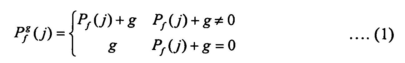
- j th element of the Reed Solomon sequence is represented as P g / ⁇ (j), which satisfies Equation (1).
- Equation (1) P 0 represents a basic orthogonal sequence in the GF (Q p ), and P f (j) represents a j th element of a cyclic shift orthogonal sequence, which is created through cyclic-shifting P 0 in the left direction by f.
- P g / ⁇ (j) is a j th element of a sequence representing the sub-channel signal interleaving pattern.
- the addition operation in Equation (1) represents the addition operation in the GF (Q P ).
- the total M(M+1) sequences used for distinguishing the BSs are determined depending on the determination schemes for parameters f and g.
- the parameters f and g are determined through one of following three schemes.
- the parameter f has a predetermined integer value selected from a predetermined integer range between 0 and M-1.
- the parameter g has a predetermined integer value selected from a predetermined integer range between 0 and M.
- the sub-channel signal interleaving pattern is allocated to the BSs through the following manner.
- the sub-channel signal interleaving pattern is adapted for M orthogonal sequences and C to M sequences including a predetermined number of sub-carriers having collision characteristics less than H sub-carriers.
- predetermined serial numbers 0 to C-1 are allocated to the C sequences. That is, the sequences having a predetermined remainder after dividing indexes of C BSs by C (C-modulo operation) are allocated to the C BSs.
- an index of a BS is an index assigned uniquely to the BS in the OFDMA communication system, so the OFDMA communication system assignes indexes to a plurality of BSs of the OFDMA communication system.
- the number of sequences orthogonal to each other is set smaller than the number of sequence representing the collision characteristics, thereby allocating the sequences having the predetermined remainder, after dividing the indexes of the BSs by C (C-modulo operation) to each BS.
- a system is designed in such a manner that the BSs having the same remainder, after dividing the indexes of the BSs by C (C-modulo operation), are spaced from each other.
- the parameters f and g are determined using Equation (2).
- a parameter PERM M
- a parameter OFFSET M+1
- c_id represents a index of the BS
- mod represents a modulo operation.
- the parameters f and g are determined by Equation (3).
- Equation (3) parameters PERM and OFFSET have the values identical to those defined in Equation (2).
- the sub-channel signal interleaving pattern for each BS is determined by using M(M+1) orthogonal sequences which satisfy Equation 1.
- the orthogonal sequences including a relatively smaller number of sub-carriers having the collision characteristics are selected to allocate the sub-channel signal interleaving pattern for each of C BSs.
- the basic orthogonal sequence P 0 can be represented as shown below through septenary notation in Equation (4).
- P 0 ⁇ 01, 22, 46, 52, 42, 41, 26, 50, 05, 33, 62, 43, 63, 65, 32, 40, 04, 11, 23, 61, 21, 24, 13, 60, 06, 55, 31, 25, 35, 36, 51, 20, 02, 44, 15, 34, 14, 12, 45, 30, 03, 66, 54, 16, 56, 53, 64, 10 ⁇ ....(4)
- the 48 x 49 sequences are allocated to each BS according to the above three schemes.
- FIG. 4 is a schematic view illustrating a procedure for transmitting the sub-channel signal in the IEEE 802.16e communication system according to an embodiment of the present invention.
- the transmitter when information data to be transmitted is generated, as described with reference to FIG. 2, the transmitter creates a modulation symbol array by performing the CRC bit insertion, encoding, and symbol mapping processes with respect to the information data in step 411.
- the transmitter interleaves the modulation symbol array according to the sub-channel signal interleaving pattern, which has been preset in the transmitter, in step 413. Because the schemes for determining the sub-channel signal interleaving pattern have already been described above, they will not again be described below.
- step 415 the transmitter allocates the interleaved sub-channel signal to the corresponding sub-channel, that is, to the sub-carriers forming the corresponding sub-channel.
- step 417 the transmitter transmits the sub-channel signal, thereby completing the procedure for transmitting the sub-channel signal.
- the sub-channel signal transmission procedure includes the steps of converting the serial signal allocated to the sub-channel to the parallel signal, inserting the pilot symbol into the parallel signal, performing the IFFT with respect to the parallel signal, converting the parallel signal into the serial signal, inserting the guard interval into the serial signal, converting the serial signal into the analog signal, and RF-processing the analog signal.
- the present invention has been described in relation to the schemes for determining the sub-channel signal interleaving pattern, the present invention is also applicable for changing the mapping position of the sub-carriers because the process for interleaving of the sub-channel signal according to the interleaving pattern is substantially identical to the process for changing the position of the sub-carriers forming the sub-channel. That is, according to the present invention, the sub-channel signal interleaving pattern can be replaced with the mapping pattern of the sub-carriers forming the sub-channel.
- the sub-channel signals allocated with the same frequency band to adjacent cells in the OFDMA communication system are transmitted by interleaving the sub-channel signals according to the sub-channel signal interleaving pattern, such that interference caused by the sub-channel signal of the adjacent cell can be minimized, thereby improving system performance.
Abstract
Description
- The present invention relates generally to a communication system using an orthogonal frequency division multiple access (OFDMA) scheme. More particularly, the present invention relates to an apparatus and a method for transmitting a sub-channel signal while minimizing interference between adjacent cells.
- Recently, various studies and research have been performed for 4th generation (4G) communication systems in order to provide subscribers with services having superior quality of service (QoS) at a higher transmission rate. In particular, many studies are being performed with the 4G communication systems in order to provide subscribers with high speed services by ensuring mobility and QoS to wireless local area network (LAN) communication systems and wireless metropolitan area network (MAN) communication systems, which can provide services at a relatively high rate.
- In order to support a broadband transmission network for a physical channel of the wireless MAN communication system, an institute of electrical and electronics engineers (IEEE) 802.16a communication system using an orthogonal frequency division multiplexing(OFDM) scheme and an OFDMA scheme has been suggested. According to the IEEE 802.16a communication system, the OFDM/OFDMA schemes are applied to the wireless MAN system to transmit a physical channel signal using a plurality of sub-carriers with a high transmission rate.
- The IEEE 802.16a communication system is based on a single cell structure without taking mobility of a subscriber station (SS) into consideration. Additionally, an IEEE 802.16e communication system, which takes mobility of the SS into consideration based on the IEEE 802.16a communication system, has been suggested. The IEEE 802.16e communication system considers the mobility of the SS under a multi-cell environment. In order to permit the mobility of the SS under the multi-cell environment, operational relationship between the SS and a base station (BS) must be changed. Accordingly, studies have been performed with a handover of the SS in order to support the mobility of the SS under a multi-cell structure. Herein, the SS having the mobility is called a mobile subscriber station (MSS).
- FIG. 1 is a schematic view illustrating a conventional IEEE 802.16e communication system. Referring to FIG. 1, the conventional IEEE 802.16e communication system has a multi-cell structure including a
cell 100 and acell 150. The conventional IEEE 802.16e communication system includes aBS 110 for managing thecell 100, aBS 140 for managing thecell 150, and a plurality ofMSSs BSs MSSs - The conventional IEEE 802.16e communication system performs an inverse fast Fourier transform (IFFT). For example, the conventional IEEE 802.16e communication system uses 1702 sub-carriers. Among the 1702 sub-carriers, 166 sub-carriers are used as pilot sub-carriers and 1536 sub-carriers are used as data sub-carriers. In addition, the 1536 sub-carriers are divided into 32 sub-channels including 48 sub-carriers, respectively. The sub-channels are allocated to the MSSs according to the state of the system. Herein, the sub-channel signifies a channel including at least one sub-carrier. For example, 48 sub-carriers may form one sub-channel.
- The sub-channel can be formed through two schemes in the conventional IEEE 802.16e communication system.
- According to the first scheme, the sub-carriers forming the sub-channels are dispersed over all frequency bands of the sub-carriers. In particular, sub-carriers are dispersed over the entire frequency band of the data sub-carriers, thereby obtaining a frequency diversity gain.
- According to the second scheme, the sub-carriers forming the sub-channels are aligned in the form of adjacent sub-carriers without being dispersed over all frequency bands of the sub-carriers.
- If the sub-channels are formed according to the second scheme, adjacent cells may use the same sub-channel in the same unit time slot. Herein, the same sub-channel signifies the sub-channels including the sub-carriers having the same frequency band. That is, as described with reference to FIG. 1, two adjacent cells (
cells 100 and 150) may use the same sub-channel in the same unit time slot. - More specifically, if
cells MSS 130, which is located in a cell boundary area, can receive the signal from theBS 110, and also from theBS 140, if the signal has high strength. For example, if the signal has a high carrier to interference and noise ratio (CINR), theMSS 130 receives the signal and demodulates the signal into information data. - If the conventional IEEE 802.16e communication system having a frequency reuse factor of 1 forms the sub-channels according to the second scheme, the sub-channels of the cells forming the conventional IEEE 802.16e communication system have the same frequency band. If the same MCS is applied to the sub-channels of the cells, the MSS located in the cell boundary area can receive the sub-channel signals not only from the BS of the MSS, but also from other BS. As a result, the MSS may receive the sub-channel signal having the higher interference component. Accordingly, it is necessary to provide an apparatus and a method for transceiving the sub-channel signal, while minimizing interference between adjacent cells.
- Accordingly, the present invention has been designed to solve the above and other problems occurring in the prior art. An object of the present invention is to provide an apparatus and a method for transmitting a sub-channel signal in an OFDMA communication system.
- Another object of the present invention is to provide an apparatus and a method for interleaving a sub-channel signal in such a manner that sub-channels having adjacent sub-carriers can be differentiated from each other according to BSs thereof in an OFDMA communication system.
- In order to accomplish the above and other objects, according to a first aspect of the present invention, there is provided a method of allocating sub-channel signal interleaving patterns to base stations (BSs) forming a wireless communication system capable of dividing a frequency band into a plurality of sub-carriers and including a plurality of sub-channels, which are a set of predetermined adjacent sub-carriers. The method comprises the steps of creating a basic orthogonal sequence having a length identical to a number of the sub-carriers forming the sub-channel; creating a plurality of sequences having lengths identical to the length of the basic orthogonal sequence by one of cyclic-shifting the basic orthogonal sequence a predetermined number of times and through performing a modulo operation based on a number of the sub-carriers forming the sub-channel, after adding a predetermined offset to the basic orthogonal sequence, which has been cyclic-shifted the predetermined number of times; selecting a predetermined number of sequences corresponding to a number of the BSs from among the plurality of sequences; and allocating the selected sequences as the sub-channel signal interleaving patterns for the BSs.
- According to another aspect of the present invention, there is provided a method of allocating sub-channel signal interleaving patterns to base stations (BSs) forming a wireless communication system capable of dividing a frequency band into a plurality of sub-carriers and including a plurality of sub-channels, which are a set of predetermined adjacent sub-carriers. The method comprises the steps of creating a basic orthogonal sequence having a length identical to a number of the sub-carriers forming the sub-channel; creating a plurality of sequences having lengths identical to the length of the basic orthogonal sequence by applying a predetermined offset to the basic orthogonal sequence, after cyclic-shifting the basic orthogonal sequence a predetermined number of times; selecting a predetermined number of sequences corresponding to a number of the BSs from among the plurality of sequences; and allocating the selected sequences as the sub-channel signal interleaving patterns for the BSs.
- According to another aspect of the present invention, there is provided a method of transmitting a sub-channel signal in a wireless communication system capable of dividing a frequency band into a plurality of sub-carriers and including a plurality of sub-channels, which are a set of predetermined adjacent sub-carriers. The method comprises the steps of creating coded bits by encoding information data to be transmitted through a predetermined coding scheme; creating a modulation symbol array by modulating the coded bits according to a predetermined modulation scheme; interleaving the modulation symbol array according to a predetermined sub-channel signal interleaving pattern; allocating the interleaved modulation symbol array to predetermined sub-channels; and transmitting the sub-channel signal, after performing an inverse fast Fourier transform (IFFT) process and an RF processing process with respect to the sub-channel signal.
- According to another aspect of the present invention, there is provided an apparatus for transmitting a sub-channel signal in a wireless communication system capable of dividing a frequency band into a plurality of sub-carriers and including a plurality of sub-channels, which are a set of predetermined adjacent sub-carriers. The apparatus comprises an encoder for creating coded bits by encoding information data to be transmitted through a predetermined coding scheme; a symbol mapper for creating a modulation symbol array by modulating the coded bits according to a predetermined modulation scheme; a sub-channel allocator for interleaving the modulation symbol array according to a predetermined sub-channel signal interleaving pattern and for allocating the interleaved modulation symbol array to predetermined sub-channels; and a transmitter for transmitting the sub-channel signal, after performing an inverse fast Fourier transform (IFFT) process and an RF processing process with respect to the sub-channel signal.
- According to another aspect of the present invention, there is provided a method of interleaving sub-channel signals for base stations (BSs) forming a wireless communication system capable of dividing a frequency band into a plurality of sub-carriers and including a plurality of sub-channels, which are a set of predetermined adjacent sub-carriers. The method comprises the steps of creating a plurality of sub-channel signal interleaving patterns, which are different from each other and have a length identical to a number of sub-carriers forming the sub-channels; and allocating the interleaving patterns to the BSs such that the sub-channel signal is interleaved.
- According to another aspect of the present invention, there is provided a method of allocating sub-channel signal interleaving patterns to base stations (BSs) in a wireless communication system capable of dividing a frequency band into a plurality of sub-carriers and including a plurality of sub-channels, which are a set of predetermined adjacent sub-carriers. The method comprises the steps of: creating a plurality of sequences having length identical to the length of a basic sequence which has a length identical to a number of data sub-carriers forming a sub-channel by applying a predetermined offset to the basic sequence and cyclic-shifting the basic sequence a predetermined number of times; allocating the created a plurality of sequences as the sub-channel signal interleaving patterns for the BSs.
- The above and other objects, features, and advantages of the present invention will be more apparent from the following detailed description taken in conjunction with the accompanying drawings, in which:
- FIG. 1 is a schematic view illustrating a conventional IEEE 802.16e communication system;
- FIG. 2 is a schematic view illustrating a transmitter for an IEEE 802.16e communication system according to an embodiment of the present invention;
- FIG. 3 is a schematic view illustrating an interleaving procedure for a sub-channel signal in an IEEE 802.16e communication system according to an embodiment of the present invention; and
- FIG. 4 is a flowchart illustrating a procedure for transmitting a sub-channel signal in an IEEE 802.16e communication system according to an embodiment of the present invention.
-
- Preferred embodiments of the present invention will be described in detail herein below with reference to the accompanying drawings. In the following detailed description, a detailed description of known functions and configurations incorporated herein will be omitted when it may obscure the subject matter of the present invention.
- The present invention is directed to an orthogonal frequency division multiple access(OFDMA) communication system. More specifically, the present invention suggests an interleaving scheme for a sub-channel signal capable of minimizing interference between adjacent cells in an institute of electrical and electronics engineers (IEEE) 802.16e communication system. That is, the present invention suggests an interleaving scheme for a sub-channel signal capable of minimizing interference between adjacent cells when the IEEE 802.16e communication system has a frequency reuse factor of 1, i.e., when cells forming the IEEE 802.16e communication system use the same frequency band.
- It should also be noted that although the present invention will be described in relation to the IEEE 802.16e communication system, the interleaving scheme for the sub-channel according to the present invention is applicable for other systems using the OFDMA scheme.
- FIG. 2 is a schematic view illustrating a transmitter for an IEEE 802.16e communication system according to an embodiment of the present invention. Referring to FIG. 2, the transmitter includes a cyclic redundancy check (CRC)
inserter 211, anencoder 213, asymbol mapper 215, asub-channel allocator 217, a serial toparallel converter 219, apilot symbol inserter 221, an inverse fast Fourier transform (IFFT)unit 223, a parallel toserial converter 225, aguard interval inserter 227, a digital toanalog converter 229, and a radio frequency (RF)processor 231. - When user data bits and control data bits to be transmitted are generated, the user data bits and control data bits are input into the
CRC inserter 211. Herein, the user data bits and control data bits are called "information data bits". TheCRC inserter 211 inserts a CRC bit into the information data bits and outputs the information data bits to theencoder 213. - Upon receiving the signal from the
CRC inserter 211, theencoder 213 codes the signal through a predetermined coding scheme and outputs the coded signal to thesymbol mapper 215. Herein, the predetermined coding scheme includes a turbo coding scheme having a predetermined coding rate or a convolutional coding scheme. - The
symbol mapper 215 modulates the coded bits output from theencoder 213 through a predetermined modulation scheme, thereby forming a modulation symbol. The modulation symbol is output to thesub-channel allocator 217. Herein, the predetermined modulation scheme includes a quadrature phase shift keying (QPSK) scheme or a 16 quadrature amplitude modulation (QAM) scheme. - The
sub-channel allocator 217 receives the modulation symbols from thesymbol mapper 215, allocates the modulation symbols to the sub-channels, and outputs the modulation symbols to the serial toparallel converter 219. Thesub-channel allocator 217 allocates the sub-channels to the modulation symbols through a predetermined scheme. That is, because the IEEE 802.16e communication system has a frequency reuse factor of 1, thesub-channel allocator 217 allocates the sub-channels to the modulation symbols, after interleaving the sub-channel signal, such that interference between adjacent cells can be minimized. This allocation scheme will be described later in detail. - Upon receiving the serial modulation symbols having the sub-channels from the
sub-channel allocator 217, the serial toparallel converter 219 parallel-converts the modulation symbols and outputs the modulation symbols to thepilot symbol inserter 221. Thepilot symbol inserter 221 inserts pilot symbols into the parallel modulation symbols and outputs the parallel modulation symbols to theIFFT unit 223. TheIFFT unit 223 receiving the signal output from thepilot symbol inserter 221 performs an N-point IFFT with respect to the signal and sends the signal to the parallel toserial converter 225. - Upon receiving the parallel signal from the
IFFT unit 223, the parallel toserial converter 225 converts parallel signal into the serial signal and outputs the serial signal to theguard interval inserter 227. After receiving the serial signal output from the parallel toserial converter 225, theguard interval inserter 227 inserts a guard interval signal into the serial signal and outputs the serial signal to the digital toanalog converter 229. Herein, the guard interval is used for removing interference between orthogonal frequency division multiplexing (OFDM) symbols, which have been transmitted in previous OFDM symbol time, and OFDM symbols to be transmitted in present OFDM symbol time when an OFDMA communication system transmits the OFDM symbols. - In addition, the guard interval can be inserted into the OFDM symbol through a cyclic prefix scheme, in which predetermined final samples of the OFDM symbols in a time domain are copied and the copied samples are inserted into effective OFDM symbols, or through a cyclic postfix scheme, in which predetermined fore samples of the OFDM symbols in the time domain are copied and the copied samples are inserted into effective OFDM symbols.
- After receiving the signal from the
guard interval inserter 227, the digital toanalog converter 229 converts the signal into an analog signal and outputs the analog signal to theRF processor 231. TheRF processor 231 includes a filter and a front end unit, and transmits the analog signal through a transmission antenna, after RF-processing the analog signal. - FIG 3 is a schematic view illustrating an interleaving procedure for the sub-channel signal in the IEEE 802.16e communication system according to an embodiment of the present invention. However, prior to explaining FIG. 3, it should be noted that the frequency reuse factor of 1 is applied to the IEEE 802.16e communication system. In addition, each of the sub-channels allocated from cells, that is, allocated from base stations(BSs) of the IEEE 802.16e communication system consists of a plurality of adjacent sub-carriers.
- As described above, the sub-channel can be formed by dispersing 48 sub-carriers over the frequency bands of the IEEE 802.16e communication system, or by aligning the sub-carriers in the form of adjacent sub-carriers, such that 48 adjacent sub-carriers may form one sub-channel.
- According to the present invention, the sub-channel is formed using the adjacent sub-carriers. In this case, as described above, the adjacent cells select the sub-channels having the same frequency band. If the same MCS is applied to the selected sub-channels, the sub-channel signals transmitted from one cell may act as interference signals with respect to other cell. Therefore, a problem may occur when restoring the signals that have been transmitted from each BS. That is, even if BSs transmit the signals with sufficient redundancy by taking interference of adjacent BSs into consideration, a subscriber station (SS) communicating with a corresponding BS may restore a signal having higher strength between a signal transmitted from the corresponding BS and an interference signal.
- The sufficient redundancy signifies a predetermined condition for restoring an original transmission signal when noise identical to the interference is received together with the signal instead of the interference signal to which the same MCS is applied.
- The reason for decoding the signal having higher strength between the receiving signal and the interference signal can be found from the characteristics of the decoder of the SS.
- The decoder of each SS is a system capable of selecting a codeword similar to a receiving signal from among all codewords available in a predetermined coding system. Accordingly, if the same MCS is applied to the same sub-channels, the decoder of each SS cannot detect the codeword transmitted from the BS making communication with the SS. As a result, the decoder only detects the codeword included in the receiving signal having highest strength. Accordingly, the SS cannot communicate with the corresponding BS.
- In order to solve this problem, the decoder is designed such that it regards only codewords transmitted from the corresponding BS as codewords generated from the coding system. Therefore, according to the present invention, the sub-channel has a function capable of distinguishing the BSs thereof. That is, although the sub-channel of each BS includes the same sub-carriers, it is possible to vary a mapping order of the symbol to the sub-carriers to enable the sub-channel to have the BS distinguishing function.
- According to the present invention, the sub-channel signal is transmitted while mapping the sub-channel signal with the sub-channel, after interleaving the sub-channel signal to be transmitted, thereby preventing the sub-channel signal from operating as the interference signal to the adjacent cells.
- FIG. 3 illustrates the interleaving scheme for the sub-channel signal used for a predetermined BS A and the interleaving scheme for the sub-channel signal used for the other BS B, which is adjacent to the BS A. It is assumed that the BSs A and B utilize N sub-carriers in which M adjacent sub-carriers form one sub-channel in a time-frequency domain. Herein, the N sub-carriers refer to a set of sub-carriers for K OFDM symbols, where K is a predetermined positive integer.
- Because the IEEE 802.16e communication system has a frequency reuse factor of 1 and forms the sub-channel by using the adjacent sub-carriers, positions of the sub-carriers forming the nth sub-channel in the BSs A and B may be identical to each other. In this case, because the sub-carriers forming the nth sub-channel in the BSs A and B have the same frequency band, the sub-channel signal is interleaved. Accordingly, the mapping order of the sub-carrier for data symbols forming the nth sub-channel signal of the BSs A and B, that is, the mapping order of the sub-carrier for modulation symbols, can be formed differently, depending on the modulation symbols.
- For example, if the IEEE 802.16e communication system utilizes 1702 sub-carriers, it is assumed that 166 sub-carriers are used as pilot sub-carriers, 1536 sub-carriers are used as data sub-carriers, and the 1536 data sub-carriers are divided into 32 sub-channels including 48 data sub-carriers, respectively. Accordingly, one sub-channel includes 48 data sub-carriers.
- Each sub-channel of the BSs A and B includes 48 data sub-carriers, including first to forty eighth data sub-carriers, in which the 48 sub-carriers have the same frequency band. In addition, assuming that the signal mapped with each sub-carrier is the modulation symbol, the sub-channel signal including 48 modulation symbols is transmitted through one sub-channel. Accordingly, the interleaving pattern of the sub-channel signal for the BS A is set differently from the interleaving pattern of the sub-channel signal for the BS B, thereby preventing the sub-channel signal transmitted from the adjacent BS from operating as the interference signal. Herein, the interleaving pattern for the sub-channel signal is referred to as a "sub-channel signal interleaving pattern".
- As illustrated in FIG. 3, according to the sub-channel signal interleaving pattern of the BS A, 48 modulation symbols are sequentially mapped with the sub-carriers of {2, 14, 1, ...., 13, 3, 9}. In addition, according to the sub-channel signal interleaving pattern of the BS B, 48 modulation symbols are sequentially mapped with the sub-carriers of {7, 13, 5, ...., 1, 8, 23}.
- The sub-channel signal interleaving patterns must be set differently from each other depending on the BSs forming the IEEE 802.16e communication system. Accordingly, the following matters must be considered when setting the sub-channel signal interleaving patterns.
- First, because one sub-channel includes M data sub-carriers, the mapping order of the sub-carrier for the modulation symbols transmitted through the sub-channel, that is, the sub-channel signal interleaving pattern, is set using a sequence having a length M including elements {0, 1, ...., M-1}. Each of the elements {0, 1, ...., M-1} is used once in the sequence having the length M. The sub-channel signal interleaving pattern can be determined through various schemes as described below by using the sequence having the length M.
- As described above, one sub-channel includes M data sub-carriers, such that it is possible to create orthogonal sequences having the length M. Herein, the orthogonal sequence signifies a sequence, in which the same elements does not exist in the same location when selecting two sequences from among orthogonal sequences having the length M.
- In addition, the orthogonal sequence having the length M can be created through various schemes as described below.
- First, orthogonal sequences having the length M, which are orthogonal to each other, can be created by enabling the sequence of {0, 1, ..., M-1} to undergo a cyclic shift by [0, M-1] times.
- Second, orthogonal sequences having the length M can be created through a computer simulation. Each of the orthogonal sequences having the length M created through the above first and second schemes is allocated as an interleaving pattern for each sub-channel signal of each BS, thereby preventing the signal of each BS from operating as the interference signal of the adjacent BS.
- If the number C of the BSs forming the IEEE 802.16e communication system is larger than the length M of the sequence, the number of the orthogonal sequences is less than the number C of the BSs, thereby making it impossible to distinguish all BSs by using the orthogonal sequence. Accordingly, a larger amount of non-orthogonal sequence is created by attenuating orthogonality of the orthogonal sequence, thereby distinguishing the BSs from each other. That is, there are provided M! sequences having the length M including elements {0, 1, ...., M-1 }, in which each of the elements {0, 1, ...., M-1} is used once in the sequence.
- In this case, when selecting two sequences from among M! sequences, it is possible to select the sequences corresponding to the number C of the BSs in which the sequences include a predetermined number of sub-carriers having collision characteristics less than H sub-carriers. In particular, if the number of sequences including a predetermined number of sub-carriers having collision characteristics less than H sub-carriers exceeds the number C of BSs, it is possible to select the sequence in such a manner that the BSs can be distinguished in an ascending order based on the number of sub-carriers having the collision characteristics.
- The non-orthogonal sequences having the length M can be created through the computer simulation. Each of the non-orthogonal sequences having the length M is allocated through the interleaving pattern of the sub-channel signal of each BS, thereby preventing the signal of each BS from operating as the interference signal of the adjacent BS.
- Among orthogonal sequences having a length M including elements {0, 1, ...., M-1}, in which each of the elements {0, 1, ...., M-1} is used once in the sequence, a predetermined orthogonal sequence So is defined as a basic orthogonal sequence. It is possible to create M2 sequences using the basic orthogonal sequence So. Hereinafter, a method for creating the M2 sequences will be described.
- First, it is assumed that a sequence S g / ƒ has a predetermined remainder after cyclic-shifting the basic orthogonal sequence So f times and dividing each element of the basic orthogonal sequence So by M, while adding an offset g to the element, in which f and g have an integer value existing within a range of [0,M-1]. That is, sequence S g / ƒ can be obtained through a modulo operation by using M. Accordingly, it is possible to create total M2 sequences S g / ƒ . The sequences, which undergo the cyclic shift by f times with the same offset g, have orthogonality to each other. The sequences having parameters g and f of different values may enable collision between elements of the sequences.
- The interleaving pattern of the sub-channel signal for each BS can be determined using the M2 orthogonal sequences. In general, the maximum number C of BSs forming the IEEE 802.16e communication system is limited to several hundreds. Therefore, it is possible to allocate the sub-channel signal interleaving pattern if the M has an integer value more than 20.
- In addition, if the number C of the BSs is less than M2, as described above, the sequences including a relatively smaller number of sub-carriers having the collision characteristics can be selected for allocating the interleaving pattern of the sub-channel signal for the C BSs.
- The sub-channel signal interleaving pattern can be determined according to the schemes for selecting the basic orthogonal sequence So. Hereinafter, the schemes for selecting the basic orthogonal sequence So will be described.
- First, the basic orthogonal sequence So is selected in such a manner that the number of sub-carriers having the collision characteristics can be minimized in each of the M2 sequences. That is, C sequences are selected corresponding to the number C of BSs in which the C sequences include a predetermined number of sub-carriers, which may present collision characteristics when selecting two sequences from among the M2 sequences, less than H sub-carriers. The selected C sequences are formed as a sequence sub-set. As described above, the C sequences that form the sequence sub-set can be selected through the computer simulation.
- When M= Q P -1, wherein Q is a decimal and p is an integer, the sub-channel signal interleaving pattern can be determined using a Reed Solomon sequence defined in a Galois Field (GF, QP). If the sub-channel signal interleaving pattern is determined using the Reed Solomon sequence, the Reed Solomon sequence may include a maximum of three sub-carriers having the collision characteristics. Herein, jth element of the Reed Solomon sequence is represented as P g / ƒ (j), which satisfies Equation (1).
- In Equation (1), P0 represents a basic orthogonal sequence in the GF (Qp), and Pf(j) represents a jth element of a cyclic shift orthogonal sequence, which is created through cyclic-shifting P0 in the left direction by f. In addition, P g / ƒ (j) is a jth element of a sequence representing the sub-channel signal interleaving pattern. The addition operation in Equation (1) represents the addition operation in the GF (QP). In addition, the total M(M+1) sequences used for distinguishing the BSs are determined depending on the determination schemes for parameters f and g.
- According to the present invention, the parameters f and g are determined through one of following three schemes.
- According to a first scheme, the parameter f has a predetermined integer value selected from a predetermined integer range between 0 and M-1. In addition, the parameter g has a predetermined integer value selected from a predetermined integer range between 0 and M.
- The sub-channel signal interleaving pattern is allocated to the BSs through the following manner.
- The sub-channel signal interleaving pattern is adapted for M orthogonal sequences and C to M sequences including a predetermined number of sub-carriers having collision characteristics less than H sub-carriers.
- First, predetermined serial numbers 0 to C-1 are allocated to the C sequences. That is, the sequences having a predetermined remainder after dividing indexes of C BSs by C (C-modulo operation) are allocated to the C BSs. Herein, an index of a BS is an index assigned uniquely to the BS in the OFDMA communication system, so the OFDMA communication system assignes indexes to a plurality of BSs of the OFDMA communication system.
- Second, among C sequences, the number of sequences orthogonal to each other is set smaller than the number of sequence representing the collision characteristics, thereby allocating the sequences having the predetermined remainder, after dividing the indexes of the BSs by C (C-modulo operation) to each BS.
- Third, a system is designed in such a manner that the BSs having the same remainder, after dividing the indexes of the BSs by C (C-modulo operation), are spaced from each other.
- According to the second scheme, the parameters f and g are determined using Equation (2).

- In Equation (2), a parameter PERM represents M (PERM = M), and a parameter OFFSET represents M+1 (OFFSET = M+1). In addition,represents a maximum integer value which is not larger than x, c_id represents a index of the BS, and mod represents a modulo operation.

- According to the third scheme, the parameters f and g are determined by Equation (3).

- In Equation (3), parameters PERM and OFFSET have the values identical to those defined in Equation (2).
- According to the above three schemes, the sub-channel signal interleaving pattern for each BS is determined by using M(M+1) orthogonal sequences which satisfy
Equation 1. - If the number C of the BSs is less than M(M+1), as described above, the orthogonal sequences including a relatively smaller number of sub-carriers having the collision characteristics are selected to allocate the sub-channel signal interleaving pattern for each of C BSs.
- Hereinafter, a procedure of allocating the sub-channel signal interleaving pattern when the number M of data sub-carriers forming one sub-channel is 48 (M = 48).
- As described above, a predetermined Reed Solomon sequence is selected from among Reed Solomon sequences having the length M = 48 = Q2-1 (Q=7) as a basic orthogonal sequence P0, thereby creating 48 x 49 sequences including a maximum of three sub-carriers having the collision characteristics. Herein, the basic orthogonal sequence P0 can be represented as shown below through septenary notation in Equation (4).
- In addition, the 48 x 49 sequences are allocated to each BS according to the above three schemes.
- FIG. 4 is a schematic view illustrating a procedure for transmitting the sub-channel signal in the IEEE 802.16e communication system according to an embodiment of the present invention. Referring to FIG. 4, when information data to be transmitted is generated, as described with reference to FIG. 2, the transmitter creates a modulation symbol array by performing the CRC bit insertion, encoding, and symbol mapping processes with respect to the information data in
step 411. The transmitter interleaves the modulation symbol array according to the sub-channel signal interleaving pattern, which has been preset in the transmitter, instep 413. Because the schemes for determining the sub-channel signal interleaving pattern have already been described above, they will not again be described below. - In
step 415, the transmitter allocates the interleaved sub-channel signal to the corresponding sub-channel, that is, to the sub-carriers forming the corresponding sub-channel. Instep 417, the transmitter transmits the sub-channel signal, thereby completing the procedure for transmitting the sub-channel signal. - As described above with reference to FIG. 2, the sub-channel signal transmission procedure includes the steps of converting the serial signal allocated to the sub-channel to the parallel signal, inserting the pilot symbol into the parallel signal, performing the IFFT with respect to the parallel signal, converting the parallel signal into the serial signal, inserting the guard interval into the serial signal, converting the serial signal into the analog signal, and RF-processing the analog signal.
- Although the present invention has been described in relation to the schemes for determining the sub-channel signal interleaving pattern, the present invention is also applicable for changing the mapping position of the sub-carriers because the process for interleaving of the sub-channel signal according to the interleaving pattern is substantially identical to the process for changing the position of the sub-carriers forming the sub-channel. That is, according to the present invention, the sub-channel signal interleaving pattern can be replaced with the mapping pattern of the sub-carriers forming the sub-channel.
- As described above, according to the present invention, the sub-channel signals allocated with the same frequency band to adjacent cells in the OFDMA communication system are transmitted by interleaving the sub-channel signals according to the sub-channel signal interleaving pattern, such that interference caused by the sub-channel signal of the adjacent cell can be minimized, thereby improving system performance.
- While the present invention has been shown and described with reference to certain preferred embodiments thereof, it will be understood by those skilled in the art that various changes in form and details may be made therein without departing from the spirit and scope of the present invention as defined by the appended claims.
Claims (36)
- A method of allocating sub-channel signal interleaving patterns to base stations (BSs) forming a wireless communication system capable of dividing a frequency band into a plurality of sub-carriers and including a plurality of sub-channels, which are a set of predetermined adjacent sub-carriers, the method comprising the steps ofcreating a basic orthogonal sequence having a length identical to a number of the sub-carriers forming the sub-channel;creating a plurality of sequences having lengths identical to the length of the basic orthogonal sequence by one of cyclic-shifting the basic orthogonal sequence a predetermined number of times and through performing a modulo operation based on a number of the sub-carriers forming the sub-channel, after adding a predetermined offset to the basic orthogonal sequence, which has been cyclic-shifted the predetermined number of times;selecting a predetermined number of sequences corresponding to a number of the BSs from among the plurality of sequences; andallocating the selected sequences as the sub-channel signal interleaving patterns for the BSs.
- The method as claimed in claim 1, wherein the basic orthogonal sequence includes a Reed Solomon sequence.
- The method as claimed in claim 1, wherein the predetermined number of sequences corresponding to the number of the BSs are selected from among the plurality of sequences in an ascending order based on a number of sub-carriers having collision characteristics included in the plurality of sequences.
- The method as claimed in claim 1, wherein the wireless communication system has a frequency reuse factor of 1.
- The method as claimed in claim 1, wherein the step of performing the modulo operation comprises the steps ofadding the predetermined offset to elements of the basic orthogonal sequence, after cyclic-shifting the basic orthogonal sequence the predetermined number of times;performing the modulo operation with respect to the elements of the sequence, to which the predetermined offset is added, based on the number of sub-carriers forming the sub-channel; andchanging the elements having values of 0 such that the elements have integer values, which can be obtained through the modulo operation and have not been applied to the elements of the modulo-operated sequence.
- A method of allocating sub-channel signal interleaving patterns to base stations (BSs) forming a wireless communication system capable of dividing a frequency band into a plurality of sub-carriers and including a plurality of sub-channels, which are a set of predetermined adjacent sub-carriers, the method comprising the steps ofcreating a basic orthogonal sequence having a length identical to a number of the sub-carriers forming the sub-channel;creating a plurality of sequences having lengths identical to the length of the basic orthogonal sequence by applying a predetermined offset to the basic orthogonal sequence, after cyclic-shifting the basic orthogonal sequence a predetermined number of times;selecting a predetermined number of sequences corresponding to a number of the BSs from among the plurality of sequences; andallocating the selected sequences as the sub-channel signal interleaving patterns for the BSs.
- The method as claimed in claim 6, wherein the step of applying the predetermined offset after cyclic-shifting the basic orthogonal sequence the predetermined number of times is determined according to:wherein, P f g (j) is a jth element of a sequence determined as the sub-channel signal interleaving pattern, Pf(j) represents a jth element of a cyclic shift orthogonal sequence, which is created through cyclic-shifting the basic orthogonal sequence in a left direction by f times, f is a predetermined integer value selected from 0 to M-1, g is the predetermined offset having a predetermined integer value from 0 to M, and M is a number of the sub-carriers forming the sub-channel.

- The method as claimed in claim 7, wherein, when M is 48, the basic orthogonal sequence is formed in a Galois field and represents {01, 22, 46, 52,42,41,26,50,05,33,62,43,63,65,32,40,04, 11, 23, 61, 21, 24, 13, 60, 06, 55,31,25,35,36,51,20,02,44, 15, 34, 14, 12, 45, 30, 03, 66, 54, 16, 56, 53, 64, 10}.
- The method as claimed in claim 6, wherein the step of applying the predetermined offset after cyclic-shifting the basic orthogonal sequence the predetermined number of times is determined according to :wherein, P g / ƒ (j) is a jth element of a sequence determined as the sub-channel signal interleaving pattern, Pf(j) represents a jth element of a cyclic shift orthogonal sequence, which is created through cyclic-shifting the basic orthogonal sequence in a left direction by f times, M is a number of the sub-carriers forming the sub-channel, and f and g, which are the predetermined offset, are determined according to :
 wherein, PERM represents M, OFFSET represents M+1,
 represents a maximum integer value, which is not larger than x, and c_id represents an index of the BS.
- The method as claimed in claim 9, wherein, when M is 48, the basic orthogonal sequence is formed in a Galois field and represents {01, 22, 46, 52, 42, 41, 26, 50, 05, 33, 62, 43, 63, 65, 32, 40, 04, 11, 23, 61, 21, 24, 13, 60, 06, 55, 31, 25, 35, 36, 51, 20, 02, 44, 15, 34, 14, 12, 45, 30, 03, 66, 54, 16, 56, 53, 64, 10}.
- The method as claimed in claim 6, wherein the step of applying the predetermined offset after cyclic-shifting the basic orthogonal sequence the predetermined number of times is determined according to :wherein, P g / ƒ (j) is a jth element of a sequence determined as the sub-channel signal interleaving pattern, Pf(j) represents a jth element of a cyclic shift orthogonal sequence, which is created through cyclic-shifting the basic orthogonal sequence in a left direction by f times, M is a number of the sub-carriers forming the sub-channel, and f and g, which are the predetermined offset, are determined according to :


- The method as claimed in claim 11, wherein, when M is 48, the basic orthogonal sequence is formed in a Galois field and represents {01, 22, 46, 52, 42, 41, 26, S0, O5, 33, 62, 43, 63, 65, 32, 40, 04, 11, 23, 61, 21, 24, 13, 60, 06, 55,31,25,35,36,51,20,02,44,15,34,14,12,45,30,03,66, 54, 16, 56, 53, 64, 10}.
- The method as claimed in claim 6, wherein the basic orthogonal sequence includes a Reed Solomon sequence.
- The method as claimed in claim 6, wherein the predetermined number of sequences corresponding to the number of the BSs are selected from among the plurality of sequences in an ascending order based on a number of sub-carriers having collision characteristics included in the sequences.
- The method as claimed in claim 6, wherein the wireless communication system has a frequency reuse factor of 1.
- A method of transmitting a sub-channel signal in a wireless communication system capable of dividing a frequency band into a plurality of sub-carriers and including a plurality of sub-channels, which are a set of predetermined adjacent sub-carriers, the method comprising the steps ofcreating coded bits by encoding information data to be transmitted through a predetermined coding scheme;creating a modulation symbol array by modulating the coded bits according to a predetermined modulation scheme;interleaving the modulation symbol array according to a predetermined sub-channel signal interleaving pattern;allocating the interleaved modulation symbol array to predetermined sub-channels; andtransmitting the sub-channel signal, after performing an inverse fast Fourier transform (IFFT) process and an RF processing process with respect to the sub-channel signal.
- The method as claimed in claim 16, wherein the sub-channel signal interleaving pattern is a sequence selected from sequences having lengths identical to a length of a basic orthogonal sequence and a number corresponding to a number of base stations, in which the sequences are created by one of cyclic-shifting the basic orthogonal sequence a predetermined number of times and through performing a modulo calculation based on a number of the sub-carriers forming the sub-channel after adding a predetermined offset to the basic orthogonal sequence, which has been cyclic-shifted the predetermined number of times.
- The method as claimed in claim 17, wherein the basic orthogonal sequence includes a Reed Solomon sequence.
- The method as claimed in claim 17, wherein the selected sequence has a minimum number of sub-carriers having collision characteristics.
- The method as claimed in claim 16, wherein the sub-channel signal interleaving pattern is a sequence selected from sequences having lengths identical to a length of a basic orthogonal sequence and a number corresponding to a number of base stations, in which the sequences are created by adding a predetermined offset to the basic orthogonal sequence, after cyclic-shifting the basic orthogonal sequence a predetermined number of times.
- The method as claimed in claim 20, wherein the basic orthogonal sequence includes a Reed Solomon sequence.
- The method as claimed in claim 20, wherein the selected sequence has a minimum number of sub-carriers having collision characteristics.
- The method as claimed in claim 16, wherein the wireless communication system has a frequency reuse factor of 1.
- An apparatus for transmitting a sub-channel signal in a wireless communication system capable of dividing a frequency band into a plurality of sub-carriers and including a plurality of sub-channels, which are a set of predetermined adjacent sub-carriers, the apparatus comprising:an encoder for creating coded bits by encoding information data to be transmitted through a predetermined coding scheme;a symbol mapper for creating a modulation symbol array by modulating the coded bits according to a predetermined modulation scheme;a sub-channel allocator for interleaving the modulation symbol array according to a predetermined sub-channel signal interleaving pattern and for allocating the interleaved modulation symbol array to predetermined sub-channels; anda transmitter for transmitting the sub-channel signal, after performing an inverse fast Fourier transform (IFFT) process and an RF processing process with respect to the sub-channel signal.
- The apparatus as claimed in claim 24, wherein the wireless communication system has a frequency reuse factor of 1.
- The apparatus as claimed in claim 24, wherein the sub-channel signal interleaving pattern is a sequence selected from sequences having lengths identical to a length of a basic orthogonal sequence and a number corresponding to a number of base stations, in which the sequences are created through adding a predetermined offset to the basic orthogonal sequence, after cyclic-shifting the basic orthogonal sequence a predetermined number of times.
- The apparatus as claimed in claim 24, wherein the sub-channel signal interleaving pattern is a sequence selected from sequences having lengths identical to a length of a basic orthogonal sequence and a number corresponding to a number of base stations, in which the sequences are created through one of cyclic-shifting the basic orthogonal sequence a predetermined number of times and performing a modulo calculation based on a number of the sub-carriers forming the sub-channel after, adding a predetermined offset to the basic orthogonal sequence which has been cyclic-shifted a predetermined number of times.
- The apparatus as claimed in claim 27, wherein the basic orthogonal sequence includes a Reed Solomon sequence.
- The apparatus as claimed in claim 27, wherein the selected sequence has a minimum number of sub-carriers having collision characteristics.
- The apparatus as claimed in claim 26, wherein the basic orthogonal sequence includes a Reed Solomon sequence.
- The apparatus as claimed in claim 26, wherein the selected sequence has a minimum number of sub-carriers having collision characteristics.
- A method of interleaving sub-channel signals for base stations (BSs) forming a wireless communication system capable of dividing a frequency band into a plurality of sub-carriers and including a plurality of sub-channels, which are a set of predetermined adjacent sub-carriers, the method comprising the steps of:creating a plurality of sub-channel signal interleaving patterns, which are different from each other and have a length identical to a number of sub-carriers forming the sub-channels; andallocating the interleaving patterns to the BSs such that the sub-channel signal is interleaved.
- A method of allocating sub-channel signal interleaving patterns to base stations (BSs) in a wireless communication system capable of dividing a frequency band into a plurality of sub-carriers and including a plurality of sub-channels, which are a set of predetermined adjacent sub-carriers, the method comprising the steps ofcreating a plurality of sequences having length identical to the length of a basic sequence which has a length identical to a number of data sub-carriers forming a sub-channel by applying a predetermined offset to the basic sequence and cyclic-shifting the basic sequence a predetermined number of times;allocating the created a plurality of sequences as the sub-channel signal interleaving patterns for the BSs.
- The method as claimed in claim 33, wherein the step of applying the predetermined offset and cyclic-shifting the basic sequence the predetermined number of times is determined according to:wherein, P g / ƒ (j) is a jth element of a sequence determined as the sub-channel signal interleaving pattern, Pf(j) represents a jth element of a cyclic shift sequence, which is created through cyclic-shifting the basic sequence in a left direction by f times, f is a predetermined integer value selected from 0 to M-1, g is the predetermined offset having a predetermined integer value from 0 to M, and M is a number of the data sub-carriers forming the sub-channel.

- The method as claimed in claim 34, wherein, when M is 48, the basic sequence is formed in a Galois field and represents {01, 22, 46, 52, 42, 41, 26, 50, 05, 33, 62, 43, 63, 65, 32, 40, 04, 11, 23, 61, 21, 24, 13, 60, 06, 55, 31, 25, 35, 36, 51, 20, 02, 44, 15, 34, 14, 12, 45, 30, 03, 66, 54, 16, 56, 53, 64, 10}.
- The method as claimed in claim 34, wherein the f and g are determined according to :wherein, PERM represents M which is a number of the data sub-carriers forming the sub-channel, OFFSET represents M+1,

Priority Applications (1)
| Application Number | Priority Date | Filing Date | Title |
|---|---|---|---|
| EP10002184.9A EP2202930B1 (en) | 2004-03-12 | 2005-03-14 | Apparatus and method for transmitting a sub-channel signal in a communication system using an orthogonal frequency division multiple access scheme |
Applications Claiming Priority (4)
| Application Number | Priority Date | Filing Date | Title |
|---|---|---|---|
| KR20040017065 | 2004-03-12 | ||
| KR2004017065 | 2004-03-12 | ||
| KR2004025145 | 2004-04-12 | ||
| KR1020040025145A KR100713528B1 (en) | 2004-03-12 | 2004-04-12 | Apparatus and method for transmitting sub-channel signal in a communication system using orthogonal frequency division multiple access scheme |
Related Child Applications (2)
| Application Number | Title | Priority Date | Filing Date |
|---|---|---|---|
| EP10002184.9A Division-Into EP2202930B1 (en) | 2004-03-12 | 2005-03-14 | Apparatus and method for transmitting a sub-channel signal in a communication system using an orthogonal frequency division multiple access scheme |
| EP10002184.9A Division EP2202930B1 (en) | 2004-03-12 | 2005-03-14 | Apparatus and method for transmitting a sub-channel signal in a communication system using an orthogonal frequency division multiple access scheme |
Publications (3)
| Publication Number | Publication Date |
|---|---|
| EP1575233A2 true EP1575233A2 (en) | 2005-09-14 |
| EP1575233A3 EP1575233A3 (en) | 2008-09-17 |
| EP1575233B1 EP1575233B1 (en) | 2015-05-20 |
Family
ID=37273275
Family Applications (2)
| Application Number | Title | Priority Date | Filing Date |
|---|---|---|---|
| EP10002184.9A Active EP2202930B1 (en) | 2004-03-12 | 2005-03-14 | Apparatus and method for transmitting a sub-channel signal in a communication system using an orthogonal frequency division multiple access scheme |
| EP20050005512 Active EP1575233B1 (en) | 2004-03-12 | 2005-03-14 | Apparatus and method for transmitting a sub-channel signal in a communication system using an orthogonal frequency division multiple access scheme |
Family Applications Before (1)
| Application Number | Title | Priority Date | Filing Date |
|---|---|---|---|
| EP10002184.9A Active EP2202930B1 (en) | 2004-03-12 | 2005-03-14 | Apparatus and method for transmitting a sub-channel signal in a communication system using an orthogonal frequency division multiple access scheme |
Country Status (10)
| Country | Link |
|---|---|
| US (3) | US7715483B2 (en) |
| EP (2) | EP2202930B1 (en) |
| JP (1) | JP4629054B2 (en) |
| KR (1) | KR100713528B1 (en) |
| CN (2) | CN1930844B (en) |
| AU (1) | AU2005222292B2 (en) |
| BR (1) | BRPI0508675B1 (en) |
| CA (1) | CA2557044C (en) |
| RU (1) | RU2349050C2 (en) |
| WO (1) | WO2005088924A1 (en) |
Cited By (1)
| Publication number | Priority date | Publication date | Assignee | Title |
|---|---|---|---|---|
| WO2007112547A1 (en) * | 2006-03-20 | 2007-10-11 | Nortel Networks Limited | Method & system for fractional frequency reuse in a wireless communication network |
Families Citing this family (40)
| Publication number | Priority date | Publication date | Assignee | Title |
|---|---|---|---|---|
| US8040986B2 (en) * | 2003-11-26 | 2011-10-18 | Texas Instruments Incorporated | Frequency-domain subchannel transmit antenna selection and power pouring for multi-antenna transmission |
| KR100617835B1 (en) | 2005-01-05 | 2006-08-28 | 삼성전자주식회사 | Apparatus and method for transmitting/receiving a channel quality information in a communication system |
| KR100965699B1 (en) * | 2005-03-25 | 2010-06-24 | 삼성전자주식회사 | Transmitting method and transmitting/receiving apparatus subchannel signal and method for allocating frequency resource in mobile communication system |
| US7610017B2 (en) * | 2005-06-09 | 2009-10-27 | Vixs Systems, Inc. | Increased data rate transmissions of a wireless communication |
| EP1903818A1 (en) * | 2005-07-29 | 2008-03-26 | Matsushita Electric Industrial Co., Ltd. | Wireless communication base station apparatus, wireless communication mobile station apparatus and pilot signal sequence allocating method in multicarrier communication |
| US7983350B1 (en) * | 2005-10-25 | 2011-07-19 | Altera Corporation | Downlink subchannelization module |
| KR100895183B1 (en) | 2006-02-03 | 2009-04-24 | 삼성전자주식회사 | Transmitting/receiving method and apparatus canceling other cell interference in wireless communication systems |
| KR101035083B1 (en) * | 2006-04-26 | 2011-05-19 | 재단법인서울대학교산학협력재단 | Method and system for using resource in a multi-cell communication system |
| CN101047393B (en) | 2006-05-12 | 2010-05-12 | 华为技术有限公司 | Method for generating interlever/de-interleaver and its application |
| JP4793569B2 (en) * | 2006-06-19 | 2011-10-12 | 日本電気株式会社 | Bandwidth allocation method and radio communication system |
| GB2458418B (en) | 2006-12-19 | 2011-08-03 | Lg Electronics Inc | Sequence generating method for efficient detection and method for transmitting and receiving signals using the same |
| JP2008160720A (en) * | 2006-12-26 | 2008-07-10 | Fujitsu Ltd | Radio base station equipped with transmitting section compatible with several sectors and transmission method of signal for several sectors |
| US8112041B2 (en) | 2007-03-14 | 2012-02-07 | Sharp Kabushiki Kaisha | Systems and methods for generating sequences that are nearest to a set of sequences with minimum average cross-correlation |
| US8611440B2 (en) | 2007-10-30 | 2013-12-17 | Huawei Technologies Co., Ltd. | Systems and methods for generating sequences that are nearest to a set of sequences with minimum average cross-correlation |
| US20080225688A1 (en) * | 2007-03-14 | 2008-09-18 | Kowalski John M | Systems and methods for improving reference signals for spatially multiplexed cellular systems |
| DK2145420T3 (en) | 2007-05-17 | 2013-01-07 | Lg Electronics Inc | Method of sending synchronization signal in wireless communication system |
| US20080310383A1 (en) * | 2007-06-15 | 2008-12-18 | Sharp Laboratories Of America, Inc. | Systems and methods for designing a sequence for code modulation of data and channel estimation |
| KR100938756B1 (en) | 2007-07-06 | 2010-01-26 | 엘지전자 주식회사 | Method for performing cell search procedure in wireless communication system |
| US8340014B2 (en) * | 2007-12-26 | 2012-12-25 | Lg Electronics Inc. | Method for transmitting and receiving signals using multi-band radio frequencies |
| JP5156485B2 (en) * | 2008-05-28 | 2013-03-06 | 株式会社エヌ・ティ・ティ・ドコモ | Wireless communication system |
| EP2131540B1 (en) * | 2008-06-04 | 2013-09-18 | Sony Corporation | New frame structure for multi-carrier systems |
| US8194529B2 (en) * | 2008-09-08 | 2012-06-05 | Sony Corporation | Frame and data pattern structure for multi-carrier systems |
| WO2010035969A2 (en) | 2008-09-23 | 2010-04-01 | Lg Electronics Inc. | Apparatus and method of transmitting and recieving data in soft handoff of a wireless communication system |
| AU2009217407C1 (en) * | 2008-10-09 | 2015-07-23 | Sony Corporation | New frame and data pattern structure for multi-carrier systems |
| US8340211B2 (en) * | 2009-06-23 | 2012-12-25 | Samsung Electronics Co., Ltd. | Methods and apparatus to encode bandwidth request message |
| KR20120069174A (en) * | 2010-12-20 | 2012-06-28 | 삼성전자주식회사 | Apparatus and method for receiving random access channel for wireless communication system |
| US8705234B2 (en) * | 2011-02-23 | 2014-04-22 | Cole Patrick Schneider | Answer bracelet |
| US9037564B2 (en) | 2011-04-29 | 2015-05-19 | Stephen Lesavich | Method and system for electronic content storage and retrieval with galois fields on cloud computing networks |
| US9361479B2 (en) | 2011-04-29 | 2016-06-07 | Stephen Lesavich | Method and system for electronic content storage and retrieval using Galois fields and geometric shapes on cloud computing networks |
| US9137250B2 (en) | 2011-04-29 | 2015-09-15 | Stephen Lesavich | Method and system for electronic content storage and retrieval using galois fields and information entropy on cloud computing networks |
| US9569771B2 (en) | 2011-04-29 | 2017-02-14 | Stephen Lesavich | Method and system for storage and retrieval of blockchain blocks using galois fields |
| CN102185815B (en) * | 2011-05-10 | 2013-04-24 | 哈尔滨工程大学 | Code position and phase position keying modulation communication method |
| EP3033880A4 (en) * | 2013-08-14 | 2017-04-26 | LG Electronics Inc. | Apparatus for transmitting broadcast signals, apparatus for receiving broadcast signals, method for transmitting broadcast signals and method for receiving broadcast signals |
| US9246635B2 (en) | 2013-11-11 | 2016-01-26 | Lg Electronics Inc. | Apparatus for transmitting broadcast signals, apparatus for receiving broadcast signals, method for transmitting broadcast signals and method for receiving broadcast signals |
| KR102217030B1 (en) * | 2014-09-12 | 2021-02-19 | 삼성전자주식회사 | Modulation/demodulation apparatus and method for tranceiving signal in a wireless communication system |
| EP3454514B1 (en) | 2016-05-11 | 2020-07-15 | Huawei Technologies Co., Ltd. | Signal transmission method, sending end and receiving end |
| EP3282662B1 (en) * | 2016-08-12 | 2021-05-12 | Institut Mines Telecom / Telecom Bretagne | Reduced complexity transmitter for universal filtered ofdm |
| US10298355B2 (en) * | 2017-02-28 | 2019-05-21 | Corning Incorporated | Supporting cooperative transmission in massive multiple-input multiple-output (MIMO) systems |
| US20220416937A1 (en) * | 2019-08-26 | 2022-12-29 | Board Of Regents, The University Of Texas System | Autoencoder-based error correction coding for low-resolution communication |
| US20220377596A1 (en) * | 2019-10-03 | 2022-11-24 | Nokia Technologies Oy | Packet-dependent logical channel restriction |
Family Cites Families (46)
| Publication number | Priority date | Publication date | Assignee | Title |
|---|---|---|---|---|
| GB2177876A (en) | 1985-07-08 | 1987-01-28 | Philips Electronic Associated | Radio system and a transmitter and a receiver for use in the system |
| IL103620A0 (en) * | 1992-11-03 | 1993-04-04 | Rafael Armament Dev Authority | Spread-spectrum,frequency-hopping radiotelephone system |
| DE19647833B4 (en) * | 1996-11-19 | 2005-07-07 | Deutsches Zentrum für Luft- und Raumfahrt e.V. | Method for simultaneous radio transmission of digital data between a plurality of subscriber stations and a base station |
| SE9700212L (en) | 1997-01-24 | 1998-07-25 | Ericsson Telefon Ab L M | Procedure and arrangement in a communication system |
| US5933421A (en) * | 1997-02-06 | 1999-08-03 | At&T Wireless Services Inc. | Method for frequency division duplex communications |
| DE19733825A1 (en) * | 1997-08-05 | 1999-02-11 | Siemens Ag | Method and arrangement for combined measurement of the start of a data block and the carrier frequency offset in a multicarrier transmission system for irregular transmission of data blocks |
| US6711120B1 (en) * | 1999-03-11 | 2004-03-23 | Flarion Technologies, Inc. | Orthogonal frequency division multiplexing based spread spectrum multiple access |
| US7406261B2 (en) | 1999-11-02 | 2008-07-29 | Lot 41 Acquisition Foundation, Llc | Unified multi-carrier framework for multiple-access technologies |
| JP3826653B2 (en) | 2000-02-25 | 2006-09-27 | Kddi株式会社 | Subcarrier allocation method for wireless communication system |
| US6928084B2 (en) * | 2000-03-28 | 2005-08-09 | At & T Corp. | OFDM communication system and method having a reduced peak-to-average power ratio |
| US6944120B2 (en) * | 2000-04-12 | 2005-09-13 | Her Majesty The Queen In Right Of Canada, As Represented By The Minister Of Industry | Method and system for tiered digital television terrestrial broadcasting services using multi-bit-stream frequency interleaved OFDM |
| US7418043B2 (en) * | 2000-07-19 | 2008-08-26 | Lot 41 Acquisition Foundation, Llc | Software adaptable high performance multicarrier transmission protocol |
| US7672381B1 (en) * | 2000-10-17 | 2010-03-02 | Motorola, Inc. | Method of multiple-carrier communication within a noncontiguous wideband spectrum and apparatus therefor |
| JP3947770B2 (en) * | 2001-03-12 | 2007-07-25 | 直樹 末広 | CDMA communication system using multiple spreading sequences |
| US7706458B2 (en) * | 2001-04-24 | 2010-04-27 | Mody Apurva N | Time and frequency synchronization in Multi-Input, Multi-Output (MIMO) systems |
| EP1265411B1 (en) | 2001-06-08 | 2007-04-18 | Sony Deutschland GmbH | Multicarrier system with adaptive bit-wise interleaving |
| JP3676991B2 (en) * | 2001-07-05 | 2005-07-27 | 松下電器産業株式会社 | Wireless communication apparatus and wireless communication method |
| US7411896B1 (en) * | 2001-08-29 | 2008-08-12 | Ostendo Technologies, Inc. | Method, apparatus, and system for power amplifier efficiency improvement |
| CN101729232B (en) * | 2001-08-30 | 2013-07-03 | 株式会社Ntt都科摩 | Radio transmission system and method |
| US20030048462A1 (en) * | 2001-09-06 | 2003-03-13 | Richard Williams | Method for generating multi-carrier sequences |
| US7483483B2 (en) * | 2001-12-06 | 2009-01-27 | Pulse-Link, Inc. | Ultra-wideband communication apparatus and methods |
| US6967598B2 (en) * | 2004-02-20 | 2005-11-22 | Bae Systems Information And Electronic Systems Integration Inc | Reduced complexity multi-turbo multi-user detector |
| KR200276049Y1 (en) * | 2002-02-25 | 2002-05-18 | 주식회사 한진중공업 | Protection tube assembly of ship's propeller shaft |
| JP3963737B2 (en) * | 2002-02-28 | 2007-08-22 | 松下電器産業株式会社 | Multi-carrier signal generation method, radio transmission apparatus, and radio reception apparatus |
| CA2477883C (en) * | 2002-03-07 | 2013-05-21 | Naftali Chayat | Hierarchical preamble constructions for ofdma based on complementary sequences |
| KR200286166Y1 (en) * | 2002-03-11 | 2002-08-22 | 주식회사 다다실업 | Cap using multicolored embroidery thread |
| KR20040000229A (en) * | 2002-06-24 | 2004-01-03 | 삼성전자주식회사 | Method and apparatus for efficient sub-channel transmission/reception of data |
| US7551546B2 (en) * | 2002-06-27 | 2009-06-23 | Nortel Networks Limited | Dual-mode shared OFDM methods/transmitters, receivers and systems |
| US7317750B2 (en) * | 2002-10-31 | 2008-01-08 | Lot 41 Acquisition Foundation, Llc | Orthogonal superposition coding for direct-sequence communications |
| KR100456701B1 (en) * | 2002-11-07 | 2004-11-10 | 삼성전자주식회사 | Multi carrier transmission system |
| US7486735B2 (en) * | 2003-02-28 | 2009-02-03 | Nortel Networks Limited | Sub-carrier allocation for OFDM |
| EP1463255A1 (en) * | 2003-03-25 | 2004-09-29 | Sony United Kingdom Limited | Interleaver for mapping symbols on the carriers of an OFDM system |
| EP1469613A1 (en) * | 2003-04-16 | 2004-10-20 | Siemens Aktiengesellschaft | Method and transmitter for data transmission in a multi-carrier system over multiple transmit antennas |
| US7421076B2 (en) * | 2003-09-17 | 2008-09-02 | Analog Devices, Inc. | Advanced encryption standard (AES) engine with real time S-box generation |
| US7535819B1 (en) * | 2003-09-26 | 2009-05-19 | Staccato Communications, Inc. | Multiband OFDM system with mapping |
| US7292606B2 (en) * | 2003-09-30 | 2007-11-06 | Texas Instruments Incorporated | Two-stage symbol alignment method for ADSL transmission in the presence of TCM-ISDN interferers |
| US7706454B2 (en) * | 2003-10-01 | 2010-04-27 | Regents Of The University Of Minnesota | Full-diversity, full-rate complex-field space-time coding for wireless communication |
| US7376117B2 (en) * | 2003-12-02 | 2008-05-20 | Infineon Technologies Ag | Interleaving circuit for a multiband OFDM transceiver |
| US7570695B2 (en) * | 2003-12-18 | 2009-08-04 | Intel Corporation | Method and adaptive bit interleaver for wideband systems using adaptive bit loading |
| US7570619B2 (en) * | 2004-02-13 | 2009-08-04 | Broadcom Corporation | Long training sequence method and device for wireless communications |
| US7444134B2 (en) * | 2004-02-13 | 2008-10-28 | Broadcom Corporation | Device and method for transmitting long training sequence for wireless communications |
| EP1763932A4 (en) * | 2004-02-17 | 2010-01-06 | Huawei Tech Co Ltd | Multiplexing scheme in a communication system |
| US7706350B2 (en) * | 2004-03-19 | 2010-04-27 | Qualcomm Incorporated | Methods and apparatus for flexible spectrum allocation in communication systems |
| US7426175B2 (en) * | 2004-03-30 | 2008-09-16 | Motorola, Inc. | Method and apparatus for pilot signal transmission |
| US7543197B2 (en) * | 2004-12-22 | 2009-06-02 | Qualcomm Incorporated | Pruned bit-reversal interleaver |
| US8340232B2 (en) * | 2005-12-09 | 2012-12-25 | Samsung Electronics Co., Ltd. | Apparatus and method for channel estimation using training signals with reduced signal overhead |
-
2004
- 2004-04-12 KR KR1020040025145A patent/KR100713528B1/en not_active IP Right Cessation
-
2005
- 2005-03-11 JP JP2006553066A patent/JP4629054B2/en active Active
- 2005-03-11 CA CA2557044A patent/CA2557044C/en active Active
- 2005-03-11 BR BRPI0508675A patent/BRPI0508675B1/en active IP Right Grant
- 2005-03-11 US US11/077,858 patent/US7715483B2/en active Active
- 2005-03-11 CN CN2005800080467A patent/CN1930844B/en active Active
- 2005-03-11 AU AU2005222292A patent/AU2005222292B2/en active Active
- 2005-03-11 CN CN201010145658.3A patent/CN101834711B/en active Active
- 2005-03-11 RU RU2006132509/09A patent/RU2349050C2/en active
- 2005-03-11 WO PCT/KR2005/000705 patent/WO2005088924A1/en active Application Filing
- 2005-03-14 EP EP10002184.9A patent/EP2202930B1/en active Active
- 2005-03-14 EP EP20050005512 patent/EP1575233B1/en active Active
-
2008
- 2008-03-17 US US12/049,706 patent/US7991062B2/en active Active
-
2011
- 2011-02-25 US US13/035,496 patent/US8462865B2/en active Active
Non-Patent Citations (1)
| Title |
|---|
| None |
Cited By (4)
| Publication number | Priority date | Publication date | Assignee | Title |
|---|---|---|---|---|
| WO2007112547A1 (en) * | 2006-03-20 | 2007-10-11 | Nortel Networks Limited | Method & system for fractional frequency reuse in a wireless communication network |
| CN101406080B (en) * | 2006-03-20 | 2010-10-06 | 北电网络有限公司 | Method & system for fractional frequency reuse in a wireless communication network |
| US8538443B2 (en) | 2006-03-20 | 2013-09-17 | Research In Motion Limited | Method and system for adjusting communication mode by adjusting the power level for a fractional frequency reuse in a wireless communication network |
| US9451467B1 (en) | 2006-03-20 | 2016-09-20 | Blackberry Limited | Method and system for fractional frequency reuse in a wireless communication network |
Also Published As
| Publication number | Publication date |
|---|---|
| US7991062B2 (en) | 2011-08-02 |
| CN101834711A (en) | 2010-09-15 |
| BRPI0508675A (en) | 2007-08-21 |
| AU2005222292B2 (en) | 2008-07-03 |
| US20050201477A1 (en) | 2005-09-15 |
| KR20050091612A (en) | 2005-09-15 |
| JP4629054B2 (en) | 2011-02-09 |
| EP1575233A3 (en) | 2008-09-17 |
| AU2005222292A1 (en) | 2005-09-22 |
| CN1930844A (en) | 2007-03-14 |
| BRPI0508675B1 (en) | 2018-07-17 |
| US20110149716A1 (en) | 2011-06-23 |
| CN101834711B (en) | 2014-05-07 |
| EP1575233B1 (en) | 2015-05-20 |
| EP2202930B1 (en) | 2018-12-19 |
| EP2202930A1 (en) | 2010-06-30 |
| CN1930844B (en) | 2011-07-27 |
| WO2005088924A1 (en) | 2005-09-22 |
| US8462865B2 (en) | 2013-06-11 |
| CA2557044A1 (en) | 2005-09-22 |
| US7715483B2 (en) | 2010-05-11 |
| KR100713528B1 (en) | 2007-05-02 |
| RU2349050C2 (en) | 2009-03-10 |
| US20080159436A1 (en) | 2008-07-03 |
| CA2557044C (en) | 2013-04-30 |
| JP2007532048A (en) | 2007-11-08 |
| RU2006132509A (en) | 2008-03-20 |
Similar Documents
| Publication | Publication Date | Title |
|---|---|---|
| CA2557044C (en) | Apparatus and method for transmitting a sub-channel signal in a communication system using an orthogonal frequency division multiple access scheme | |
| KR100876757B1 (en) | System and method for consturcting sub channel in a communication system | |
| KR100707052B1 (en) | Method and Apparatus for allocating sub-carriers in broadband wireless communication system using multiple carriers | |
| KR100842588B1 (en) | Method and Apparatus for allocating sub-carriers broadband wireless communication system using multiple carriers | |
| KR100929100B1 (en) | Apparatus and Method for Allocating Subchannels in Communication System Using Orthogonal Frequency Division Multiple Access | |
| KR100860698B1 (en) | Apparatus and method for allocating sub channels in a communication system | |
| KR101465794B1 (en) | Method of transmitting data using repetition coding |
Legal Events
| Date | Code | Title | Description |
|---|---|---|---|
| PUAI | Public reference made under article 153(3) epc to a published international application that has entered the european phase |
Free format text: ORIGINAL CODE: 0009012 |
|
| 17P | Request for examination filed |
Effective date: 20050314 |
|
| AK | Designated contracting states |
Kind code of ref document: A2 Designated state(s): AT BE BG CH CY CZ DE DK EE ES FI FR GB GR HU IE IS IT LI LT LU MC NL PL PT RO SE SI SK TR |
|
| AX | Request for extension of the european patent |
Extension state: AL BA HR LV MK YU |
|
| PUAL | Search report despatched |
Free format text: ORIGINAL CODE: 0009013 |
|
| AK | Designated contracting states |
Kind code of ref document: A3 Designated state(s): AT BE BG CH CY CZ DE DK EE ES FI FR GB GR HU IE IS IT LI LT LU MC NL PL PT RO SE SI SK TR |
|
| AX | Request for extension of the european patent |
Extension state: AL BA HR LV MK YU |
|
| AKX | Designation fees paid |
Designated state(s): DE FR GB IT SE |
|
| 17Q | First examination report despatched |
Effective date: 20100528 |
|
| RAP1 | Party data changed (applicant data changed or rights of an application transferred) |
Owner name: SAMSUNG ELECTRONICS CO., LTD. |
|
| REG | Reference to a national code |
Ref country code: DE Ref legal event code: R079 Ref document number: 602005046572 Country of ref document: DE Free format text: PREVIOUS MAIN CLASS: H04L0027260000 Ipc: H04W0028160000 |
|
| GRAP | Despatch of communication of intention to grant a patent |
Free format text: ORIGINAL CODE: EPIDOSNIGR1 |
|
| RIC1 | Information provided on ipc code assigned before grant |
Ipc: H04W 28/16 20090101AFI20141211BHEP Ipc: H04L 1/00 20060101ALI20141211BHEP Ipc: H04L 5/00 20060101ALI20141211BHEP Ipc: H04W 16/12 20090101ALI20141211BHEP |
|
| INTG | Intention to grant announced |
Effective date: 20150109 |
|
| RIN1 | Information on inventor provided before grant (corrected) |
Inventor name: JANG, JI-HO Inventor name: HUH, HOON Inventor name: YOON, SOON-YOUNG Inventor name: HWANG, IN-SEOK Inventor name: SUNG, SANG-HOON Inventor name: MAENG, SEUNG-JOO Inventor name: KIM, JEONG-HEON Inventor name: CHO, JAE-HEE Inventor name: JEON, JAE-HO |
|
| GRAS | Grant fee paid |
Free format text: ORIGINAL CODE: EPIDOSNIGR3 |
|
| GRAA | (expected) grant |
Free format text: ORIGINAL CODE: 0009210 |
|
| AK | Designated contracting states |
Kind code of ref document: B1 Designated state(s): DE FR GB IT SE |
|
| REG | Reference to a national code |
Ref country code: GB Ref legal event code: FG4D |
|
| REG | Reference to a national code |
Ref country code: DE Ref legal event code: R096 Ref document number: 602005046572 Country of ref document: DE Effective date: 20150625 |
|
| REG | Reference to a national code |
Ref country code: DE Ref legal event code: R097 Ref document number: 602005046572 Country of ref document: DE |
|
| REG | Reference to a national code |
Ref country code: FR Ref legal event code: PLFP Year of fee payment: 12 |
|
| PLBE | No opposition filed within time limit |
Free format text: ORIGINAL CODE: 0009261 |
|
| STAA | Information on the status of an ep patent application or granted ep patent |
Free format text: STATUS: NO OPPOSITION FILED WITHIN TIME LIMIT |
|
| 26N | No opposition filed |
Effective date: 20160223 |
|
| PG25 | Lapsed in a contracting state [announced via postgrant information from national office to epo] |
Ref country code: IT Free format text: LAPSE BECAUSE OF FAILURE TO SUBMIT A TRANSLATION OF THE DESCRIPTION OR TO PAY THE FEE WITHIN THE PRESCRIBED TIME-LIMIT Effective date: 20150520 |
|
| REG | Reference to a national code |
Ref country code: FR Ref legal event code: PLFP Year of fee payment: 13 |
|
| PG25 | Lapsed in a contracting state [announced via postgrant information from national office to epo] |
Ref country code: SE Free format text: LAPSE BECAUSE OF FAILURE TO SUBMIT A TRANSLATION OF THE DESCRIPTION OR TO PAY THE FEE WITHIN THE PRESCRIBED TIME-LIMIT Effective date: 20150520 |
|
| REG | Reference to a national code |
Ref country code: FR Ref legal event code: PLFP Year of fee payment: 14 |
|
| PGFP | Annual fee paid to national office [announced via postgrant information from national office to epo] |
Ref country code: FR Payment date: 20230221 Year of fee payment: 19 |
|
| PGFP | Annual fee paid to national office [announced via postgrant information from national office to epo] |
Ref country code: GB Payment date: 20230220 Year of fee payment: 19 Ref country code: DE Payment date: 20230220 Year of fee payment: 19 |