EP1575200A2 - Method and system for the clock synchronization of network terminals - Google Patents
Method and system for the clock synchronization of network terminals Download PDFInfo
- Publication number
- EP1575200A2 EP1575200A2 EP05251009A EP05251009A EP1575200A2 EP 1575200 A2 EP1575200 A2 EP 1575200A2 EP 05251009 A EP05251009 A EP 05251009A EP 05251009 A EP05251009 A EP 05251009A EP 1575200 A2 EP1575200 A2 EP 1575200A2
- Authority
- EP
- European Patent Office
- Prior art keywords
- slave
- terminals
- clock
- master
- terminal
- Prior art date
- Legal status (The legal status is an assumption and is not a legal conclusion. Google has not performed a legal analysis and makes no representation as to the accuracy of the status listed.)
- Withdrawn
Links
- 238000000034 method Methods 0.000 title claims abstract description 27
- 230000004044 response Effects 0.000 claims abstract description 22
- 230000005540 biological transmission Effects 0.000 claims description 16
- 230000000903 blocking effect Effects 0.000 claims description 4
- 230000000977 initiatory effect Effects 0.000 description 10
- 238000010586 diagram Methods 0.000 description 6
- 230000001360 synchronised effect Effects 0.000 description 5
- 230000001934 delay Effects 0.000 description 4
- 238000005259 measurement Methods 0.000 description 2
- 230000003247 decreasing effect Effects 0.000 description 1
- 230000007812 deficiency Effects 0.000 description 1
- 238000011161 development Methods 0.000 description 1
- 230000018109 developmental process Effects 0.000 description 1
- 238000005516 engineering process Methods 0.000 description 1
- 230000006870 function Effects 0.000 description 1
- 235000003642 hunger Nutrition 0.000 description 1
- 230000002452 interceptive effect Effects 0.000 description 1
- 230000001105 regulatory effect Effects 0.000 description 1
- 230000037351 starvation Effects 0.000 description 1
Images


Classifications
-
- H—ELECTRICITY
- H04—ELECTRIC COMMUNICATION TECHNIQUE
- H04L—TRANSMISSION OF DIGITAL INFORMATION, e.g. TELEGRAPHIC COMMUNICATION
- H04L7/00—Arrangements for synchronising receiver with transmitter
- H04L7/02—Speed or phase control by the received code signals, the signals containing no special synchronisation information
-
- H—ELECTRICITY
- H04—ELECTRIC COMMUNICATION TECHNIQUE
- H04J—MULTIPLEX COMMUNICATION
- H04J3/00—Time-division multiplex systems
- H04J3/02—Details
- H04J3/06—Synchronising arrangements
- H04J3/0635—Clock or time synchronisation in a network
- H04J3/0682—Clock or time synchronisation in a network by delay compensation, e.g. by compensation of propagation delay or variations thereof, by ranging
Definitions
- This invention relates to the field of data networks and, more specifically, to a method and system for synchronizing the clocks of terminal devices in a data network.
- video data comprises a series of still frames which must be played one after another in a predefined and well regulated time sequence. Accordingly, information relating to the image data must be transferred along with information relating to the timing of playback events.
- Proper transmission of video images requires a scheme to preserve signal timing attributes from a transmitting station to a receiving station.
- an audio-video signal is preferably played out at the same rate which it is transmitted. This is especially important in interactive systems where "real-time" properties are maintained. If a receiver clock is independent from a transmitter clock then the receiver may play frames slightly faster than it receives them and lead the system into a data starvation condition. Alternatively, if the receiver plays frames too slowly, then a data overflow condition may occur at a data buffer having a limited size.
- a data stream is divided into many portions or "packets" and transmitted along various paths of the network. These packets may be subject to time delays which are random in length. Sometimes and herein referred to as "jitter”, random time delays are necessarily inherent in networks which transmit data in data subsets.
- Each data packet may arrive at a receiver with a total transmission time which may vary from packet to packet.
- transmission time delays may be highly different between packets.
- audio-video data to be useful it must be transmitted through the packet network and played back in a manner where the time delays or network jitter does not show up as artifacts in the presentation level play back. In order to achieve this, it is necessary that a time base of the transmitting station be replicated at the receiver and thus the "clocks" of the terminal end are said to be synchronized.
- the present invention solves the deficiencies of the prior art by providing a method and system for the synchronization of the clocks of terminals in a data network.
- a method for synchronizing the clocks of network terminals in a network includes determining a respective round trip delay time from a master terminal having a master clock to each of the other (slave) terminals of the network and offsetting the clock of each of the slave terminals by an amount proportional to the respective determined round trip delay time such that the master terminal and each of the slave terminals have substantially the same point of reference in time.
- the method further includes, in response to a trigger signal, determining a respective phase and frequency offset between the master clock of the master terminal and the clocks of each of the slave terminals and offsetting the clocks of each of the slave terminals by an amount proportional to the determined respective offset to synchronize the clocks of each of the slave terminals to the master clock of the master terminal.
- the present invention advantageously provides a method and system for the synchronization of terminal clocks in a data network.
- various embodiments of the present invention are described herein with respect to the synchronization of the clocks of slave terminals to the clock of a master terminal in a packet network, the specific embodiments of the present invention should not be treated as limiting the scope of the invention. It will be appreciated by those skilled in the art informed by the teachings of the present invention that the concepts of the present invention may be advantageously applied in substantially any network for the synchronization of terminal clocks.
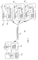
- FIG. 1 depicts a high level block diagram of a packet network including clock synchronization in accordance with an embodiment of the present invention.
- the packet network 100 of FIG. 1 illustratively comprises a master terminal 110 1 , three slave terminals 110 2 -110 4 , and a non-blocking switch 115.
- Each of the terminals comprises a clock
- the master terminal 110 1 comprises a reference master clock 120 1
- each of the slave terminals 110 2 -110 4 comprises a slave-clock generator 120 2 -120 4
- the master terminal further comprises a Reference Sync Generator 140 and a micro-controller 125 1 and each of the slave terminals 110 2 -110 4 further comprises a respective micro-controller 125 2 -125 4 .
- the slave-clocks 120 2 -120 4 of the slave terminals 110 2 -110 4 are synchronized to the master reference clock 120 1 of the master terminal 110 1 .
- each of the master terminal 110 1 and the slave terminals 110 2 -110 4 further comprise a respective network interface controller 130 1 -130 4 .
- the packet network 100 of FIG. 1 illustratively comprises a master terminal and a plurality of slave terminals, in alternate embodiments of the present invention, the concepts of the present invention may be applied in a network comprising a plurality of similar terminals wherein one of the terminals is selected to represent a master terminal having a master clock.
- the non-blocking switch 115 of FIG. 1 is known in the art and is essentially a switch that has enough paths across it that a received data packet does not have to be buffered before being switched to an intended receiver.
- the interconnection of data between the terminals 110 1 -110 4 of the packet network 100 of FIG. 1 is accomplished through the non-blocking switch 115, which will not be described in detail herein.
- FIG. 2 depicts a high level block diagram of an embodiment of a network interface controller 130 suitable for use in each of the terminals 110 1 -110 4 of the packet network 100 of FIG. 1. Because each of the interface controllers 130 1 -130 4 of the terminals 110 1 -110 4 is substantially the same, the network interface controller 130 of FIG. 2 should be considered representative of each of the interface controllers 130 1 -130 4 of the packet network 100 of FIG. 1.
- the network interface controller 130 of FIG. 2 illustratively comprises a Transmit portion and a Receive portion. The Transmit portion of the network interface controller 130 of FIG.
- the Receive portion of the of the network interface controller 130 of FIG. 2 illustratively comprises a Receive MAC 230, a Receive Buffer Manager/DMA 235, a Receive data memory (illustratively a first-in-first-out (FIFO) queue) 240, a Sync filter 245, and a Receive Sync Trigger Generator 250.
- the network interface controller 130 of FIG. 2 illustratively comprises a Receive MAC 230, a Receive Buffer Manager/DMA 235, a Receive data memory (illustratively a first-in-first-out (FIFO) queue) 240, a Sync filter 245, and a Receive Sync Trigger Generator 250.
- the Receive portion of the network interface controller 130 further comprises a Receive IP filter 275 for recognizing asynchronous data received and manipulating the received data according to conventional protocols.
- the clock for the master terminal 110 1 is provided by the reference master clock 120 1 .
- This clock supply may be an internal clock or a clock connected to the bus interface 260 residing outside of the master terminal 110 1 .
- the clock supply present in each of the slave terminals 110 2 -110 4 referred to as the slave-clocks 120 2 -120 4 may also be internal clocks or external clocks.
- the slave-clocks 120 2 -120 4 of the slave terminals 110 2 -110 4 receive synchronization data from the master terminal 110 1 in response to a trigger signal from, for example, at least one of the slave terminals 110 2 -110 4 , such that a slave-clock 120 of a requesting slave terminal 110 2 -110 4 may be synchronized to the reference master clock 120 1 of the master terminal 110 1 .
- a sync initiation signal from the Reference Sync Generator 140 defines a start time for a Sync Time Frame (described in detail below) used in synchronizing the clocks of the slave terminals 110 2 -110 4 to the master clock of the master terminal 110 1 .
- the counter 270 of the master terminal 110 1 is set to a known position (i.e., the counter of the master terminal is reset) and begins to count clock pulses of the reference master clock 120 1 .
- the counter of the master terminal 110 1 sends a signal to the Transmit Sync Trigger Generator 210 of the master terminal to generate a trigger that is communicated from the Transmit Sync Trigger Generator 210 to the Transmit Buffer Manager/DMA 215 to cause a data packet having a Sync Header stored in a specific location of the Transmit Data FIFO 220, illustratively labeled Transmit Data FIFO_sync, to be transmitted by the TX MAC 225 to one of the slave terminals, for example, the first slave terminal 110 2 .
- the first predetermined number of clock pulses defines an end of a first Sync Time Frame and the beginning of a second Sync Time Frame.
- Other data to be transmitted by the network interface controller 130 is stored in the Transmit Data FIFO 220 in a section dedicated for such transmission.
- the counter of the master terminal 110 1 sends a second signal to the Transmit Sync Trigger Generator 210 of the master terminal to generate a trigger that is communicated from the Transmit Sync Trigger Generator 210 to the Transmit Buffer Manager/DMA 215 to cause a data packet having a Sync Header to be transmitted by the TX MAC 225 to another one of the slave terminals, for example, the second slave terminal 110 3 .
- the second predetermined number of clock pulses defines an end of a second Sync Time Frame and the beginning of a third Sync Time Frame.
- the counter of the master terminal 110 1 sends a signal to the Transmit Sync Trigger Generator 210 of the master terminal to generate a trigger that is communicated from the Transmit Sync Trigger Generator 210 to the Transmit Buffer Manager/DMA 215 to cause a data packet having a Sync Header to be transmitted by the TX MAC 225 to another one of the slave terminals, for example, the third slave terminal 110 4 .
- the third predetermined number of clock pulses defines an end of the third Sync Time Frame.
- the predetermined number of counts counted by the counter 270 of the master terminal 110 1 may be defined by a user or may be a dynamic parameter that may be adjusted by the master terminal 1101 depending on the clock accuracy desired in a system (i.e., the more master clock pulses counted in a Sync Time Frame, the greater the accuracy of the synchronization between the master clock and the slave-clocks).
- the respective determined Sync Time Frame is also communicated to an intended slave terminal.
- the Receive Sync Trigger Generator 250 of the master terminal 110 1 when the counter 270 of the master terminal counts the predetermined number of clock pulses as described above, the Receive Sync Trigger Generator 250 of the master terminal 110 1 generates a trigger that is communicated to the Receive Buffer Manager/DMA 235 to notify the Receive Buffer Manager/DMA 235 that a package will be received from a slave terminal in response to the transmitted Sync packet.
- the Sync filter 245 of the first slave terminal 110 2 determines that the data packet having the sync header and the Sync Time Frame has been received from the master terminal 110 1 .
- the counter 270 of the first slave terminal 110 2 is set to known position (i.e., the counter 270 is reset).
- the counter 270 of the first slave terminal 110 2 then counts the clock pulses of its slave-clock 120 2 for a period of time equal to the respective Sync Time Frame, for example the first Sync Time Frame, recovered from the transmission from the master terminal 110 1 .
- the counter 270 stops counting and the count information is communicated to and stored in the Transmit Data FIFO 220 of the first slave terminal 110 2 .
- the counter 270 the first slave terminal 110 2 then communicates a signal to its Transmit Sync Trigger Generator 210 to generate a trigger that is communicated from the Transmit Sync Trigger Generator 210 to the Transmit Buffer Manager/DMA 215 to cause the data packet having the counter information to be transmitted by the TX MAC 225 of the first slave terminal 110 2 to the master terminal 110 1 .
- the data packet transmitted back from the first slave terminal 110 2 is received by the master terminal 110 1 and the micro-controller 125 1 of the master terminal 110 1 uses the received data packet to determine a round trip delay time for data being transmitted to the first slave terminal 110 2 and received back from the first slave terminal 110 2 . As such, the time latency for data being transmitted to the first slave terminal 110 2 from the master terminal 110 1 is determined.
- the master terminal 110 1 determines an offset for the first slave terminal 1102 using the determined relative round trip delay time and transmits the respective offset to the first slave terminal 110 2 such that the first slave terminal 110 2 and the master terminal 110 1 have the same point of reference in time.
- the round trip delay time for the other slave terminals, the second slave terminal 110 3 and the third slave terminal 110 4 , of the packet network 100 are determined in substantially the same manner. For example and as described above, after a second predetermined number of counts of the pulses of the reference master clock 120 1 of the master terminal 110 1 , the counter 270 of the master terminal 110 1 sends a signal to the Transmit Sync Trigger Generator 210 the master terminal 110 1 which generates a trigger signal that is communicated from the Transmit Sync Trigger Generator 210 to the Transmit Buffer Manager/DMA 215 to cause a data packet having a Sync header to be transmitted by the TX MAC 225 to the second slave terminal 110 3 .
- a respective determined Sync Time Frame is also communicated to the second slave terminal 110 3 .
- the signal from the counter 270 is also sent to the Receive Sync Trigger Generator 250 of the master terminal 110 1 and causes a trigger to be sent from the Receive Sync Trigger Generator 250 to the Receive Buffer Manager/DMA 235 to notify the Receive Buffer Manager/DMA 235 that a package will be received from the second slave terminal 110 3 .
- the Sync filter 245 of the second slave terminal 110 3 determines that the data packet having the Sync header and the Sync Time Frame has been received.
- the counter 270 of the second slave terminal 110 3 is set to known position (i.e., the counter 270 is reset).
- the counter 270 of the second slave terminal 110 3 then counts the clock pulses of its slave-clock 120 3 for a period of time equal to the respective Sync Time Frame, for example the second Sync Time Frame, recovered from the transmission from the master terminal 110 1 .
- the counter 270 stops counting and the count information is communicated to and stored in the Transmit Data FIFO 220 of the second slave terminal 110 3 .
- the counter 270 the second slave terminal 110 3 then communicates a signal to its Transmit Sync Trigger Generator 210 to generate a trigger that is communicated from the Transmit Sync Trigger Generator 210 to the Transmit Buffer Manager/DMA 215 to cause the data packet having the counter information to be transmitted by the TX MAC 225 to the master terminal 110 1 .
- the data packet transmitted back from the second slave terminal 1103 is received by the master terminal 110 1 where the micro-controller 125 1 of the master terminal 110 1 uses the received data packet to determine a round trip delay for a data packet being transmitted to the second slave terminal 110 3 and received back from the second slave terminal 110 3 .
- the time latency for data being transmitted to the second slave terminal 110 3 from the master terminal 110 1 is determined.
- the master terminal 110 1 determines an offset for the second slave terminal 110 3 using the determined relative round trip delay time and transmits the respective offset to the second slave terminal 110 3 such that each the second slave terminal 110 3 and the master terminal 110 1 have the same point of reference in time.
- the round trip delay times and the offsets for each of the slave terminals of a packet network in accordance with the present invention are determined in substantially the same manner using respective Sync Time Frames.
- the round trip delay measurement and offsets for the slave terminals 110 2 -110 4 is typically only required to be performed once, although, in alternate embodiments of the present invention where network conditions are changing, the round trip delay measurements may be performed periodically, for example, by the master terminal or may be performed by the master terminal in response to a trigger signal from at least one of the slave terminals.
- FIG. 3 depicts a high level block diagram of an embodiment of a micro-controller suitable for use in the master terminal 110 1 and the slave terminals 110 2 -110 4 of the packet network 100 of FIG. 1. Because each of the micro-controllers 125 1 -125 4 of the master terminal 110 1 and the slave terminals 110 2 -110 4 is substantially the same, the micro-controller 125 of FIG. 3 should be considered representative of each of the micro-controllers 125 1 -125 4 of the master terminal 110 1 and the slave terminals 110 2 -110 4 of the packet network 100 of FIG. 1.
- the micro-controller 125 of FIG. 3 comprises a processor 310 as well as a memory 320 for storing information, algorithms and control programs.
- the processor 310 cooperates with conventional support circuitry 330 such as power supplies, clock circuits, cache memory and the like as well as circuits that assist in executing the software routines stored in the memory 320. As such, it is contemplated that some of the process steps discussed herein as software processes may be implemented within hardware, for example, as circuitry that cooperates with the processor 310 to perform various steps.
- the micro-controller 125 also contains input-output circuitry 340 that forms an interface between the various functional elements communicating with the micro-controller 125.
- micro-controller 125 of FIG. 3 is depicted as a general purpose computer that is programmed to perform various control functions in accordance with the present invention
- the processes of the micro-controller 125 may be implemented in hardware, for example, as an application specified integrated circuit (ASIC).
- ASIC application specified integrated circuit
- the process steps described herein are intended to be broadly interpreted as being equivalently performed by software, hardware, or a combination thereof.
- the initial data packets received from each of the slave terminals 110 2 -110 4 are used by the micro-controller 125 1 of the master terminal 110 1 to compare the slave-clock status (i.e., the count of the respective counter of each of the slave terminals) to the status of the master clock (i.e., the count of the counter of the master terminal 110 1 for each of the respective Sync Time Frames) to determine the offset between the reference master clock 120 1 of the master terminal 110 1 and the respective slave-clocks 120 2 -120 4 of the slave terminals 110 2 -110 4 .
- the slave-clock status i.e., the count of the respective counter of each of the slave terminals
- the master clock i.e., the count of the counter of the master terminal 110 1 for each of the respective Sync Time Frames
- the returned data packet from the first slave terminal 110 2 contains information of the state of the counter (i.e., the number of slave-clock pulses counted) of the first slave terminal 110 2 .
- the micro-controller 125 1 of the master terminal 110 1 compares the state of the counter (i.e., the number of clock pulses) of the first slave terminal 110 2 to the counter of the master terminal 110 1 and determines how far the counter of the first slave terminal 110 2 , which represents the state of the slave-clock of the first slave terminal 110 2 , is offset from the reference master clock 120 1 taking into account the round trip delay time determined for the first slave terminal 110 2 .
- the slave-clock information from the first slave terminal 110 2 is compared to the master clock information for the respective Sync Time Frame, for the example above the first Sync Time Frame.
- the representative pulses of the slave-clock of the first slave terminal 110 2 are shifted by an amount proportional to the respective determined round trip delay time such that the counted clock pulses of the master clock 120 1 during the first Sync Time Frame and the counted clock pulses of the first slave terminal 110 2 during the first Sync Time Frame have the same point of reference in time.
- the phase of the clock pulses of the master clock 120 1 are then compared to the phase of the clock pulses of the first slave terminal 110 2 .
- the micro-controller 125 1 of the master terminal 110 1 determines and records a phase offset amount for the slave-clock 120 2 of the first slave terminal 110 2 .
- the counted clock pulses received from the first slave terminal 110 2 are then offset by an amount equal to the offset determined by the master terminal 110 1 .
- the number of clock pulses of the master clock 120 1 counted during the first Sync Time Frame are then compared to the number of clock pulses of the slave-clock counted by the counter of the first slave terminal 110 2 during the first Sync Time Frame. If the numbers of clock pulses are different, the micro-controller 125 1 of the master terminal 110 1 determines and records a frequency offset amount for the slave-clock 120 2 of the first slave terminal 110 2 .
- the micro-controller 125 1 of the master terminal 110 1 determines a sync signal, incorporating the phase offset and frequency offset, to transmit to the first slave terminal 110 2 .
- the micro-controller 125 2 of the first slave terminal 110 2 Upon receiving the sync signal from the master terminal 110 1 , the micro-controller 125 2 of the first slave terminal 110 2 generates a control signal to adjust the slave-clock 120 2 an amount proportional to the sync signal generated by the master terminal 110 1 to synchronize the slave-clock 120 2 of the first slave terminal 110 2 to the reference master clock 120 1 of the master terminal 110 1 .
- the slave-clocks 120 3 -120 4 of the remaining slave terminals 110 3 -110 4 are synchronized to the master clock 120 1 of the master terminal in substantially the same manner but using the slave-clock information of the slave terminals 110 3 -110 4 recorded during the respective Sync Time Frames.
- the slave-clocks are offset by a particular amount to synchronize the slave-clocks of the slave terminals to the master clock of the master terminal
- the rate of the slave-clocks of the slave terminals may be increased or decreased to synchronize the slave-clocks of the slave terminals to the master clock of the master terminal.
- the respective counters of each of the slave terminals 110 2 -110 4 are adapted to generate a signal after a respective predetermined number of counts, the signal being operative to cause the respective Transmitter Sync Trigger Generators of the slave terminals 110 2 -110 4 to generate a trigger signal.
- the trigger signal from the respective Transmitter Sync Trigger Generators are communicated to the respective Transmit Buffer Manager/DMAs to cause a respective data packet having a Sync Header to be transmitted from respective ones of the slave terminals 110 2 -110 4 to the master terminal 110 1 during the respective time intervals determined by the respective counters. For example, after a predetermined number of counts, the counter of the first slave terminal 110 2 generates a signal which is communicated to the Transmitter Sync Trigger Generator 210 of the first slave terminal 110 2 .
- the signal communicated to the Transmitter Sync Trigger Generator causes the Transmitter Sync Trigger Generator of the first slave terminal 110 2 to generate a trigger signal that is communicated to the Transmit Buffer Manager/DMA 215 causing a data packet stored in the Transmit Data FIFO 320 having a Sync Header to be transmitted by the TX MAC 225 of the first slave terminal 110 2 to the master terminal 110 1 .
- a trigger is also generated by the Receive Sync Trigger Generator 250 of the first slave terminal 110 2 and communicated to the Receive Buffer Manager/DMA 235 to notify the Receive Buffer Manager/DMA 235 that a package will be received from the master terminal 110 1 in response to the transmitted Sync packet.
- the respective predetermined number of counts counted by the respective counters of the slave terminals 110 2 -110 4 implemented for initiating synchronization may be defined by a user or may be a dynamic parameter that may be adjusted by, for example respective micro-controllers, depending on the clock accuracy desired in a system (i.e., the smaller the predetermined number of counts initiating synchronization the more often the synchronization procedure is performed).
- the respective predetermined number of counts counted by the respective counters of the slave terminals 110 2 -110 4 implemented for initiating synchronization may be adjusted during the life of a system to initially perform synchronization more frequently and as the system settles to perform synchronizations less frequently.
- the Sync filter 245 of the master terminal 110 1 determines that the data packet having the Sync header has been received.
- the counter 270 of the master terminal 110 1 is set to a known position (i.e., the counter 270 is reset) upon receiving a signal from the Reference Sync Generator 140.
- the received signal from the Reference Sync Generator defines the start of a Sync Time Frame.
- the counter 270 of the master terminal 110 1 then begins to count clock pulses of the reference master clock 120 1 .
- the counter of the master terminal 110 1 sends a signal to the Transmit Sync Trigger Generator 210 of the master terminal to generate a trigger that is communicated from the Transmit Sync Trigger Generator 210 to the Transmit Buffer Manager/DMA 215 to cause a data packet having a Sync Header to be transmitted by the TX MAC 225 to the first slave terminal 110 2 .
- the first predetermined number of clock pulses defines an end of the Sync Time Frame.
- the Sync Time Frame is also communicated to the first slave terminal 110 2 (i.e., the slave terminal initiating the synchronization of the clocks).
- the Sync filter 245 of the first slave terminal 110 2 determines that the data packet having the sync header and the Sync Time Frame has been received from the master terminal 110 1 .
- the counter 270 of the first slave terminal 110 2 is set to known position (i.e., the counter 270 is reset). The counter 270 of the first slave terminal 110 2 then counts the clock pulses of its slave-clock 120 2 for a period of time equal to the Sync Time Frame recovered from the transmission from the master terminal 110 1 .
- the counter 270 stops counting and the count information is communicated to and stored in the Transmit Data FIFO 220 of the first slave terminal 110 2 .
- the counter 270 the first slave terminal 110 2 then communicates a signal to its Transmit Sync Trigger Generator 210 to generate a trigger that is communicated from the Transmit Sync Trigger Generator 210 to the Transmit Buffer Manager/DMA 215 to cause the data packet having the counter information to be transmitted by the TX MAC 225 to the master terminal 110 1 .
- a trigger signal i.e., the transmission of a respective Sync Packet from a respective slave terminal after a predetermined number of counts
- a trigger signal i.e., the transmission of a respective Sync Packet from a respective slave terminal after a predetermined number of counts
- multi-frame triggers may be implemented.
- the Transmit Sync Generator and the Receive Sync Generator of a slave terminal may be adapted to generate a trigger for, for example, every other time a predetermined count number is reached instead of every time. That is, the Transmit Sync Generator and the Receive Sync Generator of a slave terminal may be adapted to generate a trigger after a certain number of times a predetermined count number has been counted by a respective counter (instead of generating a trigger each time a predetermined count number is counted). Even further, some slave terminals may be configured to operate on a multi-frame basis while others are configured to operate on a single frame basis.
- an initiation pulse generated by the Reference Sync Generator 140 is periodically repeated such that the slave-clocks 120 2 -120 4 of the slave terminals 110 2 -110 4 are periodically synchronized to the reference master clock 120 1 of the master terminal 110 1 .
- the initiation synchronization procedure of the present invention as disclosed above may be periodically repeated (i.e., with the exception of the determination of the round trip delay times for each of the slave terminals) according to a synchronization schedule determined by the Reference Sync Generator 140 and the transmission of an initiation pulse (i.e., the beginning of a first Sync Time Frame).
- the period for the repetition of the initiation pulse generated by the Reference Sync Generator 140 is a dynamic parameter that may be determined by a user which depends on, at least, the accuracy of the clock synchronization desired in a particular network or system.
Landscapes
- Engineering & Computer Science (AREA)
- Computer Networks & Wireless Communication (AREA)
- Signal Processing (AREA)
- Synchronisation In Digital Transmission Systems (AREA)
- Data Exchanges In Wide-Area Networks (AREA)
- Small-Scale Networks (AREA)
- Mobile Radio Communication Systems (AREA)
Abstract
Description
- This invention relates to the field of data networks and, more specifically, to a method and system for synchronizing the clocks of terminal devices in a data network.
- Recent developments and advances in information technologies have led to new and unanticipated problems. In particular, transfer of data from a server to a requesting client presents certain complication. For example, video data comprises a series of still frames which must be played one after another in a predefined and well regulated time sequence. Accordingly, information relating to the image data must be transferred along with information relating to the timing of playback events. Proper transmission of video images requires a scheme to preserve signal timing attributes from a transmitting station to a receiving station.
- For proper play-back, an audio-video signal is preferably played out at the same rate which it is transmitted. This is especially important in interactive systems where "real-time" properties are maintained. If a receiver clock is independent from a transmitter clock then the receiver may play frames slightly faster than it receives them and lead the system into a data starvation condition. Alternatively, if the receiver plays frames too slowly, then a data overflow condition may occur at a data buffer having a limited size.
- In certain transmission networks a data stream is divided into many portions or "packets" and transmitted along various paths of the network. These packets may be subject to time delays which are random in length. Sometimes and herein referred to as "jitter", random time delays are necessarily inherent in networks which transmit data in data subsets. Each data packet may arrive at a receiver with a total transmission time which may vary from packet to packet. Depending upon the network path and network congestion conditions, transmission time delays may be highly different between packets. For audio-video data to be useful, it must be transmitted through the packet network and played back in a manner where the time delays or network jitter does not show up as artifacts in the presentation level play back. In order to achieve this, it is necessary that a time base of the transmitting station be replicated at the receiver and thus the "clocks" of the terminal end are said to be synchronized.
- The present invention solves the deficiencies of the prior art by providing a method and system for the synchronization of the clocks of terminals in a data network.
- In one embodiment of the present invention, a method for synchronizing the clocks of network terminals in a network includes determining a respective round trip delay time from a master terminal having a master clock to each of the other (slave) terminals of the network and offsetting the clock of each of the slave terminals by an amount proportional to the respective determined round trip delay time such that the master terminal and each of the slave terminals have substantially the same point of reference in time. The method further includes, in response to a trigger signal, determining a respective phase and frequency offset between the master clock of the master terminal and the clocks of each of the slave terminals and offsetting the clocks of each of the slave terminals by an amount proportional to the determined respective offset to synchronize the clocks of each of the slave terminals to the master clock of the master terminal.
- The teachings of the present invention can be readily understood by considering the following detailed description in conjunction with the accompanying drawings, in which:
- FIG. 1 depicts a high level block diagram of a packet network including clock synchronization in accordance with an embodiment of the present invention;
- FIG. 2 depicts a high level block diagram of an embodiment of a network interface controller suitable for use in each of the terminals of the packet network of FIG. 1; and
- FIG. 3 depicts a high level block diagram of an embodiment of a micro-controller suitable for use in the master terminal and the slave terminals of the packet network of FIG. 1.
-
- To facilitate understanding, identical reference numerals have been used, where possible, to designate identical elements that are common to the figures.
- The present invention advantageously provides a method and system for the synchronization of terminal clocks in a data network. Although various embodiments of the present invention are described herein with respect to the synchronization of the clocks of slave terminals to the clock of a master terminal in a packet network, the specific embodiments of the present invention should not be treated as limiting the scope of the invention. It will be appreciated by those skilled in the art informed by the teachings of the present invention that the concepts of the present invention may be advantageously applied in substantially any network for the synchronization of terminal clocks.
- FIG. 1 depicts a high level block diagram of a packet network including clock synchronization in accordance with an embodiment of the present invention. The
packet network 100 of FIG. 1 illustratively comprises a master terminal 1101, three slave terminals 1102-1104, and anon-blocking switch 115. Each of the terminals comprises a clock, where the master terminal 1101 comprises a reference master clock 1201 and each of the slave terminals 1102-1104 comprises a slave-clock generator 1202-1204. The master terminal further comprises aReference Sync Generator 140 and a micro-controller 1251 and each of the slave terminals 1102-1104 further comprises a respective micro-controller 1252-1254. In thepacket network 100 of FIG. 1 in accordance with the present invention, in order to keep data exchange and any circuit means in the network as simplified as possible, the slave-clocks 1202-1204 of the slave terminals 1102-1104 are synchronized to the master reference clock 1201 of the master terminal 1101. As depicted in FIG. 1, each of the master terminal 1101 and the slave terminals 1102-1104 further comprise a respective network interface controller 1301-1304. Although thepacket network 100 of FIG. 1 illustratively comprises a master terminal and a plurality of slave terminals, in alternate embodiments of the present invention, the concepts of the present invention may be applied in a network comprising a plurality of similar terminals wherein one of the terminals is selected to represent a master terminal having a master clock. - The
non-blocking switch 115 of FIG. 1 is known in the art and is essentially a switch that has enough paths across it that a received data packet does not have to be buffered before being switched to an intended receiver. The interconnection of data between the terminals 1101-1104 of thepacket network 100 of FIG. 1 is accomplished through thenon-blocking switch 115, which will not be described in detail herein. - FIG. 2 depicts a high level block diagram of an embodiment of a
network interface controller 130 suitable for use in each of the terminals 1101-1104 of thepacket network 100 of FIG. 1. Because each of the interface controllers 1301-1304 of the terminals 1101-1104 is substantially the same, thenetwork interface controller 130 of FIG. 2 should be considered representative of each of the interface controllers 1301-1304 of thepacket network 100 of FIG. 1. Thenetwork interface controller 130 of FIG. 2 illustratively comprises a Transmit portion and a Receive portion. The Transmit portion of thenetwork interface controller 130 of FIG. 2 illustratively comprises a TransmitSync Trigger Generator 210, a Transmit Buffer Manager/DMA 215, a Transmit data queue (illustratively a first-in-first-out (FIFO) memory) 220, and a TransmitMAC 225. The Receive portion of the of thenetwork interface controller 130 of FIG. 2 illustratively comprises aReceive MAC 230, a Receive Buffer Manager/DMA 235, a Receive data memory (illustratively a first-in-first-out (FIFO) queue) 240, aSync filter 245, and a ReceiveSync Trigger Generator 250. Thenetwork interface controller 130 of FIG. 2 further comprises aBus Interface 260 common to both the Transmit portion and the Receive portion of the network interface controller and acounter 270. The Receive portion of thenetwork interface controller 130 further comprises aReceive IP filter 275 for recognizing asynchronous data received and manipulating the received data according to conventional protocols. - As previously disclosed, in the
packet network 100 of FIG. 1, the clock for the master terminal 1101 is provided by the reference master clock 1201. This clock supply may be an internal clock or a clock connected to thebus interface 260 residing outside of the master terminal 1101. Furthermore, the clock supply present in each of the slave terminals 1102-1104, referred to as the slave-clocks 1202-1204 may also be internal clocks or external clocks. In accordance with the present invention, the slave-clocks 1202-1204 of the slave terminals 1102-1104 receive synchronization data from the master terminal 1101 in response to a trigger signal from, for example, at least one of the slave terminals 1102-1104, such that a slave-clock 120 of a requesting slave terminal 1102-1104 may be synchronized to the reference master clock 1201 of the master terminal 1101. - In the
packet network 100 of FIG. 1, a sync initiation signal from theReference Sync Generator 140 defines a start time for a Sync Time Frame (described in detail below) used in synchronizing the clocks of the slave terminals 1102-1104 to the master clock of the master terminal 1101. Upon receiving the initiation signal from theReference Sync Generator 140, thecounter 270 of the master terminal 1101 is set to a known position (i.e., the counter of the master terminal is reset) and begins to count clock pulses of the reference master clock 1201. When thecounter 270 of the master terminal counts a predetermined number of clock pulses, the counter of the master terminal 1101 sends a signal to the TransmitSync Trigger Generator 210 of the master terminal to generate a trigger that is communicated from the Transmit Sync Trigger Generator 210 to the Transmit Buffer Manager/DMA 215 to cause a data packet having a Sync Header stored in a specific location of the Transmit Data FIFO 220, illustratively labeled Transmit Data FIFO_sync, to be transmitted by the TX MAC 225 to one of the slave terminals, for example, the first slave terminal 1102. The first predetermined number of clock pulses defines an end of a first Sync Time Frame and the beginning of a second Sync Time Frame. Other data to be transmitted by thenetwork interface controller 130 is stored in the Transmit Data FIFO 220 in a section dedicated for such transmission. - When the
counter 270 of the master terminal counts a second predetermined number of clock pulses, the counter of the master terminal 1101 sends a second signal to the Transmit Sync Trigger Generator 210 of the master terminal to generate a trigger that is communicated from the Transmit Sync Trigger Generator 210 to the Transmit Buffer Manager/DMA 215 to cause a data packet having a Sync Header to be transmitted by the TX MAC 225 to another one of the slave terminals, for example, the second slave terminal 1103. The second predetermined number of clock pulses defines an end of a second Sync Time Frame and the beginning of a third Sync Time Frame. When thecounter 270 of the master terminal counts a third predetermined number of clock pulses, the counter of the master terminal 1101 sends a signal to the Transmit Sync Trigger Generator 210 of the master terminal to generate a trigger that is communicated from the Transmit Sync Trigger Generator 210 to the Transmit Buffer Manager/DMA 215 to cause a data packet having a Sync Header to be transmitted by the TX MAC 225 to another one of the slave terminals, for example, the third slave terminal 1104. The third predetermined number of clock pulses defines an end of the third Sync Time Frame. The predetermined number of counts counted by thecounter 270 of the master terminal 1101 may be defined by a user or may be a dynamic parameter that may be adjusted by themaster terminal 1101 depending on the clock accuracy desired in a system (i.e., the more master clock pulses counted in a Sync Time Frame, the greater the accuracy of the synchronization between the master clock and the slave-clocks). In addition to the Sync packet, the respective determined Sync Time Frame is also communicated to an intended slave terminal. - Likewise, when the
counter 270 of the master terminal counts the predetermined number of clock pulses as described above, the ReceiveSync Trigger Generator 250 of the master terminal 1101 generates a trigger that is communicated to the Receive Buffer Manager/DMA 235 to notify the Receive Buffer Manager/DMA 235 that a package will be received from a slave terminal in response to the transmitted Sync packet. - For example, when the first slave terminal 1102 receives the data packet having the Sync Header and the Sync Time Frame, the
Sync filter 245 of the first slave terminal 1102 determines that the data packet having the sync header and the Sync Time Frame has been received from the master terminal 1101. In response, thecounter 270 of the first slave terminal 1102 is set to known position (i.e., thecounter 270 is reset). Thecounter 270 of the first slave terminal 1102 then counts the clock pulses of its slave-clock 1202 for a period of time equal to the respective Sync Time Frame, for example the first Sync Time Frame, recovered from the transmission from the master terminal 1101. At the completion of the first Sync Time Frame, thecounter 270 stops counting and the count information is communicated to and stored in the TransmitData FIFO 220 of the first slave terminal 1102. Thecounter 270 the first slave terminal 1102 then communicates a signal to its TransmitSync Trigger Generator 210 to generate a trigger that is communicated from the TransmitSync Trigger Generator 210 to the Transmit Buffer Manager/DMA 215 to cause the data packet having the counter information to be transmitted by theTX MAC 225 of the first slave terminal 1102 to the master terminal 1101. - The data packet transmitted back from the first slave terminal 1102 is received by the master terminal 1101 and the
micro-controller 1251 of the master terminal 1101 uses the received data packet to determine a round trip delay time for data being transmitted to the first slave terminal 1102 and received back from the first slave terminal 1102. As such, the time latency for data being transmitted to the first slave terminal 1102 from the master terminal 1101 is determined. The master terminal 1101 then determines an offset for thefirst slave terminal 1102 using the determined relative round trip delay time and transmits the respective offset to the first slave terminal 1102 such that the first slave terminal 1102 and the master terminal 1101 have the same point of reference in time. - The round trip delay time for the other slave terminals, the second slave terminal 1103 and the third slave terminal 1104, of the
packet network 100 are determined in substantially the same manner. For example and as described above, after a second predetermined number of counts of the pulses of the reference master clock 1201 of the master terminal 1101, thecounter 270 of the master terminal 1101 sends a signal to the TransmitSync Trigger Generator 210 the master terminal 1101 which generates a trigger signal that is communicated from the TransmitSync Trigger Generator 210 to the Transmit Buffer Manager/DMA 215 to cause a data packet having a Sync header to be transmitted by theTX MAC 225 to the second slave terminal 1103. In addition to the Sync packet, a respective determined Sync Time Frame is also communicated to the second slave terminal 1103. As previously described, the signal from thecounter 270 is also sent to the ReceiveSync Trigger Generator 250 of the master terminal 1101 and causes a trigger to be sent from the ReceiveSync Trigger Generator 250 to the Receive Buffer Manager/DMA 235 to notify the Receive Buffer Manager/DMA 235 that a package will be received from the second slave terminal 1103. - When the second slave terminal 1103 receives the data packet having the Sync Header and the second Sync Time Frame, the
Sync filter 245 of the second slave terminal 1103 determines that the data packet having the Sync header and the Sync Time Frame has been received. In response, thecounter 270 of the second slave terminal 1103 is set to known position (i.e., thecounter 270 is reset). Thecounter 270 of the second slave terminal 1103 then counts the clock pulses of its slave-clock 1203 for a period of time equal to the respective Sync Time Frame, for example the second Sync Time Frame, recovered from the transmission from the master terminal 1101. At the completion of the second Sync Time Frame, thecounter 270 stops counting and the count information is communicated to and stored in the TransmitData FIFO 220 of the second slave terminal 1103. Thecounter 270 the second slave terminal 1103 then communicates a signal to its TransmitSync Trigger Generator 210 to generate a trigger that is communicated from the TransmitSync Trigger Generator 210 to the Transmit Buffer Manager/DMA 215 to cause the data packet having the counter information to be transmitted by theTX MAC 225 to the master terminal 1101. - As before, the data packet transmitted back from the
second slave terminal 1103 is received by the master terminal 1101 where themicro-controller 1251 of the master terminal 1101 uses the received data packet to determine a round trip delay for a data packet being transmitted to the second slave terminal 1103 and received back from the second slave terminal 1103. As such, the time latency for data being transmitted to the second slave terminal 1103 from the master terminal 1101 is determined. The master terminal 1101 then determines an offset for the second slave terminal 1103 using the determined relative round trip delay time and transmits the respective offset to the second slave terminal 1103 such that each the second slave terminal 1103 and the master terminal 1101 have the same point of reference in time. The round trip delay times and the offsets for each of the slave terminals of a packet network in accordance with the present invention are determined in substantially the same manner using respective Sync Time Frames. The round trip delay measurement and offsets for the slave terminals 1102-1104 is typically only required to be performed once, although, in alternate embodiments of the present invention where network conditions are changing, the round trip delay measurements may be performed periodically, for example, by the master terminal or may be performed by the master terminal in response to a trigger signal from at least one of the slave terminals. - FIG. 3 depicts a high level block diagram of an embodiment of a micro-controller suitable for use in the master terminal 1101 and the slave terminals 1102-1104 of the
packet network 100 of FIG. 1. Because each of the micro-controllers 1251-1254 of the master terminal 1101 and the slave terminals 1102-1104 is substantially the same, themicro-controller 125 of FIG. 3 should be considered representative of each of the micro-controllers 1251-1254 of the master terminal 1101 and the slave terminals 1102-1104 of thepacket network 100 of FIG. 1. Themicro-controller 125 of FIG. 3 comprises aprocessor 310 as well as amemory 320 for storing information, algorithms and control programs. Theprocessor 310 cooperates withconventional support circuitry 330 such as power supplies, clock circuits, cache memory and the like as well as circuits that assist in executing the software routines stored in thememory 320. As such, it is contemplated that some of the process steps discussed herein as software processes may be implemented within hardware, for example, as circuitry that cooperates with theprocessor 310 to perform various steps. Themicro-controller 125 also contains input-output circuitry 340 that forms an interface between the various functional elements communicating with themicro-controller 125. - Although the
micro-controller 125 of FIG. 3 is depicted as a general purpose computer that is programmed to perform various control functions in accordance with the present invention, the processes of themicro-controller 125 may be implemented in hardware, for example, as an application specified integrated circuit (ASIC). As such, the process steps described herein are intended to be broadly interpreted as being equivalently performed by software, hardware, or a combination thereof. - In addition to determining the round trip delay time for each of the slave terminals, the initial data packets received from each of the slave terminals 1102-1104 are used by the
micro-controller 1251 of the master terminal 1101 to compare the slave-clock status (i.e., the count of the respective counter of each of the slave terminals) to the status of the master clock (i.e., the count of the counter of the master terminal 1101 for each of the respective Sync Time Frames) to determine the offset between the reference master clock 1201 of the master terminal 1101 and the respective slave-clocks 1202-1204 of the slave terminals 1102-1104. For example, when the master terminal 1101 receives the data packet back from the first slave terminal 1102 in response to the Sync data packet and, for example, the first Sync Time Frame, sent from the master terminal 1101 to the first slave terminal 1102 as described above, the returned data packet from the first slave terminal 1102 contains information of the state of the counter (i.e., the number of slave-clock pulses counted) of the first slave terminal 1102. Themicro-controller 1251 of the master terminal 1101 compares the state of the counter (i.e., the number of clock pulses) of the first slave terminal 1102 to the counter of the master terminal 1101 and determines how far the counter of the first slave terminal 1102, which represents the state of the slave-clock of the first slave terminal 1102, is offset from the reference master clock 1201 taking into account the round trip delay time determined for the first slave terminal 1102. - More specifically, in one embodiment of the present invention, the slave-clock information from the first slave terminal 1102 is compared to the master clock information for the respective Sync Time Frame, for the example above the first Sync Time Frame. The representative pulses of the slave-clock of the first slave terminal 1102 are shifted by an amount proportional to the respective determined round trip delay time such that the counted clock pulses of the master clock 1201 during the first Sync Time Frame and the counted clock pulses of the first slave terminal 1102 during the first Sync Time Frame have the same point of reference in time. The phase of the clock pulses of the master clock 1201 are then compared to the phase of the clock pulses of the first slave terminal 1102. If the phases are offset, the
micro-controller 1251 of the master terminal 1101 determines and records a phase offset amount for the slave-clock 1202 of the first slave terminal 1102. The counted clock pulses received from the first slave terminal 1102 are then offset by an amount equal to the offset determined by the master terminal 1101. The number of clock pulses of the master clock 1201 counted during the first Sync Time Frame are then compared to the number of clock pulses of the slave-clock counted by the counter of the first slave terminal 1102 during the first Sync Time Frame. If the numbers of clock pulses are different, themicro-controller 1251 of the master terminal 1101 determines and records a frequency offset amount for the slave-clock 1202 of the first slave terminal 1102. Themicro-controller 1251 of the master terminal 1101 then determines a sync signal, incorporating the phase offset and frequency offset, to transmit to the first slave terminal 1102. Upon receiving the sync signal from the master terminal 1101, themicro-controller 1252 of the first slave terminal 1102 generates a control signal to adjust the slave-clock 1202 an amount proportional to the sync signal generated by the master terminal 1101 to synchronize the slave-clock 1202 of the first slave terminal 1102 to the reference master clock 1201 of the master terminal 1101. The slave-clocks 1203-1204 of the remaining slave terminals 1103-1104 are synchronized to the master clock 1201 of the master terminal in substantially the same manner but using the slave-clock information of the slave terminals 1103-1104 recorded during the respective Sync Time Frames. - Although the embodiment described above depicts a specific method having ordered steps for determining a sync signal to synchronize the clock of the slave terminals to the master clock of the master terminal, the specific embodiment should not be treated as limiting the scope of the invention. It will be appreciated by those skilled in the art informed by the teachings of the present invention that various other methods and procedures may be implemented within the concepts of the present invention for determining a phase offset and a frequency offset between at least two clock signals. Furthermore, although in the embodiment of the invention described above it is described that the slave-clocks are offset by a particular amount to synchronize the slave-clocks of the slave terminals to the master clock of the master terminal, also within the concepts of the present invention, the rate of the slave-clocks of the slave terminals may be increased or decreased to synchronize the slave-clocks of the slave terminals to the master clock of the master terminal.
- In an embodiment of the present invention, for subsequent synchronizations of slave-clocks of slave terminals of a packet network to a master clock of a master terminal (i.e., synchronizations initiated by transmissions other than the initial transmission of a data packet with a Sync header and Sync Time Frame from the master terminal 11 01 to the slave terminals 1102-1104) the respective counters of each of the slave terminals 1102-1104 are adapted to generate a signal after a respective predetermined number of counts, the signal being operative to cause the respective Transmitter Sync Trigger Generators of the slave terminals 1102-1104 to generate a trigger signal. The trigger signal from the respective Transmitter Sync Trigger Generators are communicated to the respective Transmit Buffer Manager/DMAs to cause a respective data packet having a Sync Header to be transmitted from respective ones of the slave terminals 1102-1104 to the master terminal 1101 during the respective time intervals determined by the respective counters. For example, after a predetermined number of counts, the counter of the first slave terminal 1102 generates a signal which is communicated to the Transmitter
Sync Trigger Generator 210 of the first slave terminal 1102. The signal communicated to the Transmitter Sync Trigger Generator causes the Transmitter Sync Trigger Generator of the first slave terminal 1102 to generate a trigger signal that is communicated to the Transmit Buffer Manager/DMA 215 causing a data packet stored in the TransmitData FIFO 320 having a Sync Header to be transmitted by theTX MAC 225 of the first slave terminal 1102 to the master terminal 1101. As previously disclosed, a trigger is also generated by the ReceiveSync Trigger Generator 250 of the first slave terminal 1102 and communicated to the Receive Buffer Manager/DMA 235 to notify the Receive Buffer Manager/DMA 235 that a package will be received from the master terminal 1101 in response to the transmitted Sync packet. The respective predetermined number of counts counted by the respective counters of the slave terminals 1102-1104 implemented for initiating synchronization may be defined by a user or may be a dynamic parameter that may be adjusted by, for example respective micro-controllers, depending on the clock accuracy desired in a system (i.e., the smaller the predetermined number of counts initiating synchronization the more often the synchronization procedure is performed). In addition, the respective predetermined number of counts counted by the respective counters of the slave terminals 1102-1104 implemented for initiating synchronization may be adjusted during the life of a system to initially perform synchronization more frequently and as the system settles to perform synchronizations less frequently. - Upon receiving the data packet having the Sync Header, the
Sync filter 245 of the master terminal 1101 determines that the data packet having the Sync header has been received. In response, thecounter 270 of the master terminal 1101 is set to a known position (i.e., thecounter 270 is reset) upon receiving a signal from theReference Sync Generator 140. As previously disclosed, the received signal from the Reference Sync Generator defines the start of a Sync Time Frame. Thecounter 270 of the master terminal 1101 then begins to count clock pulses of the reference master clock 1201. When thecounter 270 of the master terminal counts a predetermined number of clock pulses, the counter of the master terminal 1101 sends a signal to the TransmitSync Trigger Generator 210 of the master terminal to generate a trigger that is communicated from the TransmitSync Trigger Generator 210 to the Transmit Buffer Manager/DMA 215 to cause a data packet having a Sync Header to be transmitted by theTX MAC 225 to the first slave terminal 1102. As previously disclosed, the first predetermined number of clock pulses defines an end of the Sync Time Frame. In addition to the Sync packet, the Sync Time Frame is also communicated to the first slave terminal 1102 (i.e., the slave terminal initiating the synchronization of the clocks). - When the first slave terminal 1102 receives the data packet having the Sync Header and the Sync Time Frame, the
Sync filter 245 of the first slave terminal 1102 determines that the data packet having the sync header and the Sync Time Frame has been received from the master terminal 1101. In response, thecounter 270 of the first slave terminal 1102 is set to known position (i.e., thecounter 270 is reset). Thecounter 270 of the first slave terminal 1102 then counts the clock pulses of its slave-clock 1202 for a period of time equal to the Sync Time Frame recovered from the transmission from the master terminal 1101. At the completion of the first Sync Time Frame, thecounter 270 stops counting and the count information is communicated to and stored in the TransmitData FIFO 220 of the first slave terminal 1102. Thecounter 270 the first slave terminal 1102 then communicates a signal to its TransmitSync Trigger Generator 210 to generate a trigger that is communicated from the TransmitSync Trigger Generator 210 to the Transmit Buffer Manager/DMA 215 to cause the data packet having the counter information to be transmitted by theTX MAC 225 to the master terminal 1101. - The synchronization procedure then continues as disclosed above for the initial synchronization procedure. Briefly stated, the example of a subsequent synchronization procedure disclosed above defines that a trigger signal (i.e., the transmission of a respective Sync Packet from a respective slave terminal after a predetermined number of counts) from any of the slave terminals 1102-1104 is operative for causing the synchronization procedure of the present invention to occur as disclosed above for the initial synchronization procedure. It should be noted, however, in alternate embodiments of the present invention, multi-frame triggers may be implemented. More specifically, to account for and accommodate different data rates that may occur in a network in accordance with the present invention, the Transmit Sync Generator and the Receive Sync Generator of a slave terminal may be adapted to generate a trigger for, for example, every other time a predetermined count number is reached instead of every time. That is, the Transmit Sync Generator and the Receive Sync Generator of a slave terminal may be adapted to generate a trigger after a certain number of times a predetermined count number has been counted by a respective counter (instead of generating a trigger each time a predetermined count number is counted). Even further, some slave terminals may be configured to operate on a multi-frame basis while others are configured to operate on a single frame basis.
- In an alternate embodiment of the present invention, for subsequent synchronizations of slave-clocks of slave terminals of a packet network to a master clock of a master terminal (i.e., synchronizations initiated by transmissions other than the initial transmission of a data packet with a Sync header and the Sync Time Frame from the master terminal 1101 to the slave terminals 1102-1104), an initiation pulse generated by the
Reference Sync Generator 140 is periodically repeated such that the slave-clocks 1202-1204 of the slave terminals 1102-1104 are periodically synchronized to the reference master clock 1201 of the master terminal 1101. More specifically, the initiation synchronization procedure of the present invention as disclosed above may be periodically repeated (i.e., with the exception of the determination of the round trip delay times for each of the slave terminals) according to a synchronization schedule determined by theReference Sync Generator 140 and the transmission of an initiation pulse (i.e., the beginning of a first Sync Time Frame). The period for the repetition of the initiation pulse generated by theReference Sync Generator 140 is a dynamic parameter that may be determined by a user which depends on, at least, the accuracy of the clock synchronization desired in a particular network or system. - While the forgoing is directed to various embodiments of the present invention, other and further embodiments of the invention may be devised without departing from the basic scope thereof. As such, the appropriate scope of the invention is to be determined according to the claims, which follow.
Claims (10)
- A method for synchronizing clocks of network terminals in a network, comprising:selecting a clock of one of said network terminals to be a master clock;determining a respective round trip delay time from said network terminal having said master clock to each of said other terminals;offsetting the clock of each of said other terminals by an amount proportional to the respective determined round trip delay time such that said network terminal having said master clock and each of said other terminals have substantially the same point of reference in time; andin response to at least one trigger signal, determining a respective offset between the master clock and the clocks of each of said other terminals and offsetting the clocks of each of said other terminals by an amount proportional to said determined respective offset to synchronize the clocks of each of said other terminals to said master clock.
- The method of claim 1, wherein said selected network terminal comprises a master terminal and said other network terminals comprise slave terminals.
- The method of claim 1, wherein said determining a respective round trip delay time, comprises:transmitting a respective data packet from said terminal including the master clock to each of said other terminals; anddetermining, from respective data packets received from each of said other terminals in response to said transmitted respective data packets, a respective amount of time for data packets to be transmitted to and received from each of said other terminals.
- The method of claim 1, wherein said respective offset for each of the other terminals is determined comprising:in response to a synchronization signal, counting a predetermined number of clock pulses of said master clock;counting clock pulses of the clocks of said other terminals for a period of time equal to the amount of time for counting said predetermined number of clock pulses of said master clock and beginning at a point in time of said synchronization signal; andcomparing the phase and frequency of the counted clock pulses of each of the other terminals to the clock pulses of said master terminal to determine a respective offset.
- The method of claim 1, wherein each of said other terminals respectively triggers the synchronization of its respective clock to the master clock.
- A network for synchronizing clocks of network terminals in said network, comprising:wherein said master control unit comprises a memory and a processor and is adapted to perform a method comprising:a synchronization device for providing a timing signal;a master terminal, including:a master clock for providing timing information for said master terminal;a master network interface controller for transmitting data from and receiving data for said master terminal; anda master control unit for determining synchronization parameters;a plurality of slave terminals, each of said slave terminals including:anda slave-clock for providing timing information for said slave terminal;a slave controller for making adjustments to said slave-clock in response to a control signal indicative of a difference between said master clock and said slave-clock; anda slave network interface controller for transmitting data from and receiving data for said slave terminal;a non-blocking switch for interconnecting said master terminal and said plurality of slave terminals;determining a respective round trip delay time for each of said plurality of slave terminals;communicating a control signal to respective slave controllers of the plurality of slave terminals for offsetting the slave-clock of each of said slave terminals by an amount proportional to the respective determined round trip delay time such that said master terminal and each of said slave terminals have substantially the same point of reference in time;determining a respective offset between the master clock and a respective slave-clock of each of said slave terminals in response to information received from each of said slave terminals regarding a status of the respective slave-clocks; andoffsetting a respective slave-clock of each of said slave terminals by an amount proportional to said determined respective offset to synchronize the slave-clock of each of said slave terminals to the master clock of said master terminal.
- The network of claim 6, wherein each of said network interface controllers comprises:a counting device for generating a signal in response to counting a predetermined number of counts;a transmit trigger generator for receiving the signal from said counter and, in response, generating a transmit trigger signal;a transmit memory device, for storing data to be transmitted;a transmit memory manager for receiving the transmit trigger signal from said transmit trigger generator and, in response, directing at least a portion of said data stored in said memory device to a transmission device for transmission of said data;a receive trigger generator for receiving the signal from said counter and, in response, generating a receive trigger signal;a receive memory device, for storing received data; anda receive memory manager for receiving the receive trigger signal from said receive trigger generator and, in response, directing received data to a location within said receive memory device.
- The network of claim 7, wherein each of said counting devices begins counting from a predetermined count number in response to a timing signal from said synchronization device.
- The network of claim 6, wherein said synchronization device generates a time frame for the synchronization of the respective slave-clocks of said plurality of slave terminals to the master clock of said master terminal.
- The network of claim 6, wherein said master terminal transmits a data packet having a Sync header and a timing signal to each of said plurality of slave terminals to cause each of said slave terminals to transmit information regarding a status of their respective slave-clocks to the master terminal.
Applications Claiming Priority (2)
| Application Number | Priority Date | Filing Date | Title |
|---|---|---|---|
| US797915 | 1997-02-10 | ||
| US10/797,915 US7483448B2 (en) | 2004-03-10 | 2004-03-10 | Method and system for the clock synchronization of network terminals |
Publications (2)
| Publication Number | Publication Date |
|---|---|
| EP1575200A2 true EP1575200A2 (en) | 2005-09-14 |
| EP1575200A3 EP1575200A3 (en) | 2005-12-07 |
Family
ID=34827646
Family Applications (1)
| Application Number | Title | Priority Date | Filing Date |
|---|---|---|---|
| EP05251009A Withdrawn EP1575200A3 (en) | 2004-03-10 | 2005-02-22 | Method and system for the clock synchronization of network terminals |
Country Status (5)
| Country | Link |
|---|---|
| US (1) | US7483448B2 (en) |
| EP (1) | EP1575200A3 (en) |
| JP (1) | JP4856382B2 (en) |
| KR (1) | KR101126091B1 (en) |
| CN (1) | CN1667997B (en) |
Cited By (4)
| Publication number | Priority date | Publication date | Assignee | Title |
|---|---|---|---|---|
| US7483448B2 (en) | 2004-03-10 | 2009-01-27 | Alcatel-Lucent Usa Inc. | Method and system for the clock synchronization of network terminals |
| EP2178250A1 (en) | 2008-10-15 | 2010-04-21 | Yamaha Corporation | Network system and audio signal processor |
| GB2532950A (en) * | 2014-12-02 | 2016-06-08 | Cirrus Logic Int Semiconductor Ltd | Digital accessory interface calibration |
| WO2016181097A1 (en) * | 2015-05-11 | 2016-11-17 | Cirrus Logic International Semiconductor Limited | Digital accessory interface calibration |
Families Citing this family (74)
| Publication number | Priority date | Publication date | Assignee | Title |
|---|---|---|---|---|
| SE528607C2 (en) * | 2004-04-30 | 2006-12-27 | Kvaser Consultant Ab | System and device for temporarily relating events in a vehicle |
| SE525930C2 (en) * | 2004-07-23 | 2005-05-31 | Kvaser Consultant Ab | Modularised system for time stamping transactions, used for computer system analysis, uses module memory to store time stamps given to reference transactions |
| US20060168379A1 (en) * | 2004-12-13 | 2006-07-27 | Tim Frodsham | Method, system, and apparatus for link latency management |
| US8149866B2 (en) * | 2005-10-14 | 2012-04-03 | Dell Products L.P. | System and method for filtering communications at a network interface controller |
| US20080122986A1 (en) * | 2006-09-19 | 2008-05-29 | Florian Diederichsen | Method and system for live video production over a packeted network |
| US7978680B1 (en) | 2007-03-28 | 2011-07-12 | Marvell International Ltd. | System and method for synchronizing clocks in a wireless local area network |
| US8054382B2 (en) * | 2007-05-21 | 2011-11-08 | International Business Machines Corporation | Apparatus, method and system for synchronizing a common broadcast signal among multiple television units |
| JP5130858B2 (en) * | 2007-10-03 | 2013-01-30 | ヤマハ株式会社 | Triangular wave synchronization generation system and triangular wave synchronization generation circuit used therefor |
| CN101425865B (en) * | 2007-10-31 | 2013-04-24 | 电信科学技术研究院 | Method and system for synchronizing clock of transmission network as well as subordinate clock side entity |
| JP5389039B2 (en) * | 2007-11-02 | 2014-01-15 | ノヴァテル インコーポレイテッド | System and method for distributing accurate time and frequency across a network |
| EP2210122B1 (en) * | 2007-11-13 | 2018-02-07 | NovAtel Inc. | System for determining position over a network |
| US7680154B2 (en) * | 2007-12-31 | 2010-03-16 | Intel Corporation | Methods and apparatus for synchronizing networked audio devices |
| JP2011521238A (en) * | 2008-05-22 | 2011-07-21 | ノヴァテル インコーポレイテッド | GNSS receiver using convenient communication signals and support information to shorten initial positioning time |
| EP2150062B1 (en) * | 2008-07-28 | 2022-10-26 | Imagine Communications Corp. | Improved method, system and apparatus for synchronizing signals |
| KR101421523B1 (en) * | 2008-09-30 | 2014-07-24 | 에스케이텔레콤 주식회사 | Network synchronization system and network synchronization method |
| CN101431795B (en) * | 2008-11-29 | 2012-10-10 | 中兴通讯股份有限公司 | Time synchronization method and apparatus |
| US8370675B2 (en) * | 2009-01-28 | 2013-02-05 | Mellanox Technologies Ltd. | Precise clock synchronization |
| US8165171B2 (en) * | 2009-03-19 | 2012-04-24 | Raytheon Bbn Technologies Corp. | Methods and systems for distributed synchronization |
| JP5470649B2 (en) * | 2009-08-31 | 2014-04-16 | 独立行政法人情報通信研究機構 | Short-range wireless communication system and method |
| EP2299614B1 (en) * | 2009-09-17 | 2018-08-15 | Siemens Aktiengesellschaft | Device and method for time synchronisation in a communication network |
| TWI421667B (en) * | 2009-10-07 | 2014-01-01 | Univ Nat Cheng Kung | Method of clock synchronization and internet system using the same |
| KR101232929B1 (en) * | 2009-11-23 | 2013-02-15 | 한국전자통신연구원 | Method and apparatus for time synchronization of distributed nodes over wideband high frequency wireless |
| CN102098194B (en) * | 2009-12-10 | 2014-02-05 | 中兴通讯股份有限公司 | Method and system for realizing time synchronization in local area network |
| JP5509055B2 (en) * | 2009-12-24 | 2014-06-04 | キヤノンファインテック株式会社 | Image forming apparatus |
| WO2011124948A1 (en) | 2010-04-08 | 2011-10-13 | Freescale Semiconductor, Inc. | Multi-channel sniffer system and method for multi-channel sniffer synchronization |
| CN102006157B (en) * | 2010-11-26 | 2015-01-28 | 中兴通讯股份有限公司 | Time synchronization method and system |
| MY168816A (en) * | 2011-07-20 | 2018-12-04 | Aviat Networks Inc | Systems and methods of network synchronization |
| DE112012006890B4 (en) * | 2012-09-11 | 2020-03-26 | Mitsubishi Electric Corporation | Correction parameter calculation device, system, correction parameter calculation method, and computer program |
| KR102060496B1 (en) * | 2013-02-12 | 2019-12-30 | 삼성전자주식회사 | Terminal apparatus and method for time synchronization |
| KR101492910B1 (en) * | 2013-02-15 | 2015-02-12 | 서울시립대학교 산학협력단 | Method and system for ethercat-based distributed clokc synchronization |
| US20140310553A1 (en) * | 2013-04-10 | 2014-10-16 | Xun Chen | Hardware and software for synchronized data acquisition from multiple devices |
| KR101649754B1 (en) * | 2014-04-30 | 2016-08-19 | 주식회사 이에스엠연구소 | Control signal transmitting method in distributed system for multiview cameras and distributed system for multiview cameras |
| US10237836B2 (en) * | 2014-06-09 | 2019-03-19 | Parallel Wireless, Inc. | Frequency and phase synchronization using full duplex radios over wireless mesh networks |
| KR102377555B1 (en) | 2014-07-29 | 2022-03-22 | 삼성전자 주식회사 | Electronic device and clock control method thereof |
| CN104320240B (en) * | 2014-11-03 | 2016-08-17 | 武汉数字派特科技有限公司 | A kind of provide the method and apparatus of global clock in system |
| US10671596B1 (en) * | 2015-03-31 | 2020-06-02 | EMC IP Holding Company LLC | Consistency determination |
| CN105119675B (en) * | 2015-06-29 | 2018-11-06 | 上海华为技术有限公司 | A kind of synchronous method and synchronization system of target device |
| KR101708398B1 (en) | 2015-08-12 | 2017-03-08 | 전자부품연구원 | Synchronization method for terminal on profiled network and networking apparatus performing the same |
| KR101656705B1 (en) * | 2016-06-24 | 2016-09-12 | 주식회사 효성기술 | Radar device which can determine the reflection distance using reference signal and Pulse signal |
| CN108111244B (en) * | 2016-11-25 | 2019-08-13 | 上海东软医疗科技有限公司 | A kind of methods, devices and systems of clock correction |
| EP3622659B1 (en) * | 2017-05-12 | 2022-12-07 | Seakr Engineering, Inc. | Pulse-based synchronization training for synchronous digital and mixed-signal systems |
| US10877919B2 (en) * | 2017-07-21 | 2020-12-29 | Integrated Device Technology, Inc. | Method to synchronize integrated circuits fulfilling functional safety requirements |
| US11483127B2 (en) | 2018-11-18 | 2022-10-25 | Mellanox Technologies, Ltd. | Clock synchronization |
| US10778406B2 (en) | 2018-11-26 | 2020-09-15 | Mellanox Technologies, Ltd. | Synthesized clock synchronization between networks devices |
| US11283454B2 (en) | 2018-11-26 | 2022-03-22 | Mellanox Technologies, Ltd. | Synthesized clock synchronization between network devices |
| US11368183B2 (en) * | 2019-06-21 | 2022-06-21 | Ensco, Inc. | Systems and methods for synchronizing time, frequency, and phase among a plurality of devices |
| KR102229559B1 (en) * | 2019-08-29 | 2021-03-18 | 주식회사 효원파워텍 | System and method for clock synchronization based on ethercat network |
| CN112615691A (en) * | 2019-10-06 | 2021-04-06 | 上海淡竹体育科技有限公司 | Method for accurately aligning time among multiple terminals of timing type sports test system |
| US11543852B2 (en) | 2019-11-07 | 2023-01-03 | Mellanox Technologies, Ltd. | Multihost clock synchronization |
| US11070304B1 (en) | 2020-02-25 | 2021-07-20 | Mellanox Technologies, Ltd. | Physical hardware clock chaining |
| US12081427B2 (en) | 2020-04-20 | 2024-09-03 | Mellanox Technologies, Ltd. | Time-synchronization testing in a network element |
| US11552871B2 (en) | 2020-06-14 | 2023-01-10 | Mellanox Technologies, Ltd. | Receive-side timestamp accuracy |
| US11606427B2 (en) | 2020-12-14 | 2023-03-14 | Mellanox Technologies, Ltd. | Software-controlled clock synchronization of network devices |
| CN112532309B (en) * | 2020-12-21 | 2022-07-22 | 四川安迪科技实业有限公司 | Physical layer transmission method and device suitable for simple satellite internet of things terminal |
| US11588609B2 (en) | 2021-01-14 | 2023-02-21 | Mellanox Technologies, Ltd. | Hardware clock with built-in accuracy check |
| TWI748892B (en) * | 2021-03-08 | 2021-12-01 | 瑞昱半導體股份有限公司 | Clock synchronization system and method for operating a clock synchronization system |
| US12111681B2 (en) | 2021-05-06 | 2024-10-08 | Mellanox Technologies, Ltd. | Network adapter providing isolated self-contained time services |
| US12028155B2 (en) | 2021-11-24 | 2024-07-02 | Mellanox Technologies, Ltd. | Controller which adjusts clock frequency based on received symbol rate |
| US11907754B2 (en) | 2021-12-14 | 2024-02-20 | Mellanox Technologies, Ltd. | System to trigger time-dependent action |
| KR20230099898A (en) | 2021-12-28 | 2023-07-05 | 삼성전자주식회사 | Electronic device and method to manage and use sensing time point for localization |
| US11835999B2 (en) | 2022-01-18 | 2023-12-05 | Mellanox Technologies, Ltd. | Controller which adjusts clock frequency based on received symbol rate |
| US11706014B1 (en) | 2022-01-20 | 2023-07-18 | Mellanox Technologies, Ltd. | Clock synchronization loop |
| US12532279B2 (en) * | 2022-02-18 | 2026-01-20 | Mellanox Technologies, Ltd. | Scheduling 5G functions using a network adapter |
| US12524038B2 (en) | 2022-05-12 | 2026-01-13 | Mellanox Technologies, Ltd | Scalable boundary clock |
| US12294469B2 (en) | 2022-05-12 | 2025-05-06 | Mellanox Technologies, Ltd | Boundary clock synchronized loop |
| US12308952B2 (en) | 2022-07-06 | 2025-05-20 | Mellanox Technologies, Ltd. | Companion metadata for precision time protocol (PTP) hardware clock |
| US12289388B2 (en) | 2022-07-20 | 2025-04-29 | Mellanox Technologies, Ltd | Syntonization through physical layer of interconnects |
| US11917045B2 (en) | 2022-07-24 | 2024-02-27 | Mellanox Technologies, Ltd. | Scalable synchronization of network devices |
| US12375199B2 (en) | 2022-12-19 | 2025-07-29 | Mellanox Technologies, Ltd | Hybrid clock synchronization |
| US12216489B2 (en) | 2023-02-21 | 2025-02-04 | Mellanox Technologies, Ltd | Clock adjustment holdover |
| US12669843B2 (en) | 2023-07-11 | 2026-06-30 | Mellanox Technologies, Ltd | Clock synchronization monitoring system |
| US12289389B2 (en) | 2023-08-13 | 2025-04-29 | Mellanox Technologies, Ltd. | Physical layer syntonization using digitally controlled oscillator |
| US12645251B2 (en) | 2023-09-20 | 2026-06-02 | Mellanox Technologies, Ltd | Offloaded intra-system synchronization |
| US12615130B2 (en) | 2024-04-02 | 2026-04-28 | Mellanox Technologies, Ltd | Environmental-based parameters optimization of clock |
Family Cites Families (13)
| Publication number | Priority date | Publication date | Assignee | Title |
|---|---|---|---|---|
| US4005266A (en) * | 1975-07-14 | 1977-01-25 | The Singer Company | Method and apparatus for synchronizing master and local time base systems |
| JPS6352089A (en) * | 1986-08-22 | 1988-03-05 | Hitachi Ltd | Time synchronizing system for network |
| KR970020202U (en) * | 1995-10-20 | 1997-05-26 | Clock Supply Circuit on Digital Trunk Interface Board | |
| FI104592B (en) * | 1996-07-19 | 2000-02-29 | Nokia Networks Oy | Maintaining synchronization in a telecommunications network |
| JPH10285140A (en) * | 1997-04-02 | 1998-10-23 | Mitsubishi Electric Corp | Time synchronization system and time synchronization method in time synchronization system |
| SE509836C2 (en) * | 1997-06-13 | 1999-03-15 | Ericsson Telefon Ab L M | Procedure and arrangement in a radio communication system |
| US6373834B1 (en) * | 1997-12-19 | 2002-04-16 | Telefonaktiebolaget Lm Ericsson | Synchronization for cellular telecommunications network |
| US6246702B1 (en) * | 1998-08-19 | 2001-06-12 | Path 1 Network Technologies, Inc. | Methods and apparatus for providing quality-of-service guarantees in computer networks |
| DE60041470D1 (en) * | 1999-05-11 | 2009-03-19 | Canon Kk | Method and apparatus for synchronization between two networks |
| US7068746B1 (en) * | 2000-03-01 | 2006-06-27 | Lucent Technologies Inc. | Base station transceiver to radio network controller synchronization filtering function |
| US6577872B1 (en) * | 2000-08-08 | 2003-06-10 | Telefonaktiebolaget Lm Ericsson (Publ) | Base station oscillator regulation independent of transport network clocks in cellular telecommunications network |
| CN1175625C (en) * | 2002-11-12 | 2004-11-10 | 威盛电子股份有限公司 | Clock synchronization method and wireless local area network medium access controller |
| US7483448B2 (en) | 2004-03-10 | 2009-01-27 | Alcatel-Lucent Usa Inc. | Method and system for the clock synchronization of network terminals |
-
2004
- 2004-03-10 US US10/797,915 patent/US7483448B2/en not_active Expired - Lifetime
-
2005
- 2005-02-22 EP EP05251009A patent/EP1575200A3/en not_active Withdrawn
- 2005-03-04 KR KR1020050018230A patent/KR101126091B1/en not_active Expired - Fee Related
- 2005-03-09 CN CN2005100527364A patent/CN1667997B/en not_active Expired - Fee Related
- 2005-03-10 JP JP2005066767A patent/JP4856382B2/en not_active Expired - Fee Related
Non-Patent Citations (1)
| Title |
|---|
| None |
Cited By (13)
| Publication number | Priority date | Publication date | Assignee | Title |
|---|---|---|---|---|
| US7483448B2 (en) | 2004-03-10 | 2009-01-27 | Alcatel-Lucent Usa Inc. | Method and system for the clock synchronization of network terminals |
| EP2178250A1 (en) | 2008-10-15 | 2010-04-21 | Yamaha Corporation | Network system and audio signal processor |
| EP2405613A1 (en) * | 2008-10-15 | 2012-01-11 | Yamaha Corporation | Network system and audio signal processor |
| US9166816B2 (en) | 2008-10-15 | 2015-10-20 | Yamaha Corporation | Network system and audio signal processor |
| US9836274B2 (en) | 2014-12-02 | 2017-12-05 | Cirrus Logic, Inc. | Digital accessory interface calibration |
| WO2016087815A1 (en) * | 2014-12-02 | 2016-06-09 | Cirrus Logic International Semiconductor Limited | Digital accessory interface calibration |
| GB2542970A (en) * | 2014-12-02 | 2017-04-05 | Cirrus Logic Int Semiconductor Ltd | Digital accessory interface calibration |
| GB2532950B (en) * | 2014-12-02 | 2017-04-12 | Cirrus Logic Int Semiconductor Ltd | Digital accessory interface calibration |
| GB2532950A (en) * | 2014-12-02 | 2016-06-08 | Cirrus Logic Int Semiconductor Ltd | Digital accessory interface calibration |
| GB2542970B (en) * | 2014-12-02 | 2018-08-08 | Cirrus Logic Int Semiconductor Ltd | Digital accessory interface calibration |
| US10642570B2 (en) | 2014-12-02 | 2020-05-05 | Cirrus Logic, Inc. | Digital accessory interface calibration |
| WO2016181097A1 (en) * | 2015-05-11 | 2016-11-17 | Cirrus Logic International Semiconductor Limited | Digital accessory interface calibration |
| US10042796B2 (en) | 2015-05-11 | 2018-08-07 | Cirrus Logic, Inc. | Digital accessory interface calibration |
Also Published As
| Publication number | Publication date |
|---|---|
| CN1667997A (en) | 2005-09-14 |
| US20050201421A1 (en) | 2005-09-15 |
| CN1667997B (en) | 2011-12-14 |
| KR20060043423A (en) | 2006-05-15 |
| KR101126091B1 (en) | 2012-04-12 |
| JP2005260966A (en) | 2005-09-22 |
| US7483448B2 (en) | 2009-01-27 |
| JP4856382B2 (en) | 2012-01-18 |
| EP1575200A3 (en) | 2005-12-07 |
Similar Documents
| Publication | Publication Date | Title |
|---|---|---|
| US7483448B2 (en) | Method and system for the clock synchronization of network terminals | |
| CN104137488B (en) | Network devices with time-aware media access controllers | |
| US7511764B2 (en) | Digital camera synchronization | |
| US9307298B2 (en) | System and method for video statistical multiplexing adapting to internet protocol networks | |
| US8190680B2 (en) | Method and system for synchronization of digital media playback | |
| US20060251046A1 (en) | Master-slave synchronization communication method | |
| CN104243129B (en) | Receiver, method of calculating time difference, and computer-readable storage medium | |
| GB2426164A (en) | Network time synchronisation using a determination of network element transit times | |
| CN106210503B (en) | Camera shutter synchronization control method and device in vehicle Ethernet communication network | |
| JP2018510567A (en) | Wireless synchronization based on beacons | |
| CN101496322A (en) | Consistent Distributed Timestamp Counter | |
| EP2090003A2 (en) | Apparatus and method of controlled delay packet forwarding | |
| JP3673268B1 (en) | Jitter correction device | |
| AU2006295218A1 (en) | Compressed video packet scheduling system | |
| JP4542027B2 (en) | Time synchronization method, time client, time server, application device, and time synchronization system | |
| JP2022096504A (en) | Communication equipment, control methods and programs for communication equipment | |
| JP2004500758A (en) | Synchronization of voice packet generation and unsolicited grant in voice telephony with DOCSIS cable modem packets | |
| US7684413B2 (en) | System and method for rate agile adaptive clocking in a packet-based network | |
| US20040218633A1 (en) | Method for multiplexing, in MPEG stream processor, packets of several input MPEG streams into one output transport stream with simultaneous correction of time stamps | |
| CN114337890A (en) | Multi-terminal broadcast synchronization system and method based on PTP network synchronization | |
| US12200291B2 (en) | Reception apparatus, reception method, and transmission and reception system | |
| US20110026654A1 (en) | Network device of high-precision synchronization type, network system, and frame transfer method | |
| JP4002413B2 (en) | Network imaging device | |
| US6880098B1 (en) | Timing recovery in a packet network using a buffer | |
| US20250159338A1 (en) | Imaging system, imaging apparatus, method for controlling imaging system, method for controlling imaging apparatus, and storage medium |
Legal Events
| Date | Code | Title | Description |
|---|---|---|---|
| PUAI | Public reference made under article 153(3) epc to a published international application that has entered the european phase |
Free format text: ORIGINAL CODE: 0009012 |
|
| 17P | Request for examination filed |
Effective date: 20050310 |
|
| AK | Designated contracting states |
Kind code of ref document: A2 Designated state(s): AT BE BG CH CY CZ DE DK EE ES FI FR GB GR HU IE IS IT LI LT LU MC NL PL PT RO SE SI SK TR |
|
| AX | Request for extension of the european patent |
Extension state: AL BA HR LV MK YU |
|
| PUAL | Search report despatched |
Free format text: ORIGINAL CODE: 0009013 |
|
| AK | Designated contracting states |
Kind code of ref document: A3 Designated state(s): AT BE BG CH CY CZ DE DK EE ES FI FR GB GR HU IE IS IT LI LT LU MC NL PL PT RO SE SI SK TR |
|
| AX | Request for extension of the european patent |
Extension state: AL BA HR LV MK YU |
|
| AKX | Designation fees paid |
Designated state(s): DE FR GB |
|
| RAP3 | Party data changed (applicant data changed or rights of an application transferred) |
Owner name: LUCENT TECHNOLOGIES INC. |
|
| RAP1 | Party data changed (applicant data changed or rights of an application transferred) |
Owner name: ALCATEL-LUCENT USA INC. |
|
| RAP1 | Party data changed (applicant data changed or rights of an application transferred) |
Owner name: ALCATEL LUCENT |
|
| 111Z | Information provided on other rights and legal means of execution |
Free format text: DE FR GB Effective date: 20130410 |
|
| RAP1 | Party data changed (applicant data changed or rights of an application transferred) |
Owner name: ALCATEL LUCENT |
|
| STAA | Information on the status of an ep patent application or granted ep patent |
Free format text: STATUS: THE APPLICATION IS DEEMED TO BE WITHDRAWN |
|
| 18D | Application deemed to be withdrawn |
Effective date: 20140424 |