EP1575148A1 - Power tool - Google Patents
Power tool Download PDFInfo
- Publication number
- EP1575148A1 EP1575148A1 EP05005140A EP05005140A EP1575148A1 EP 1575148 A1 EP1575148 A1 EP 1575148A1 EP 05005140 A EP05005140 A EP 05005140A EP 05005140 A EP05005140 A EP 05005140A EP 1575148 A1 EP1575148 A1 EP 1575148A1
- Authority
- EP
- European Patent Office
- Prior art keywords
- stator
- rotor
- gap
- power tool
- permanent magnets
- Prior art date
- Legal status (The legal status is an assumption and is not a legal conclusion. Google has not performed a legal analysis and makes no representation as to the accuracy of the status listed.)
- Granted
Links
Images


Classifications
-
- H—ELECTRICITY
- H02—GENERATION; CONVERSION OR DISTRIBUTION OF ELECTRIC POWER
- H02K—DYNAMO-ELECTRIC MACHINES
- H02K9/00—Arrangements for cooling or ventilating
- H02K9/26—Structural association of machines with devices for cleaning or drying cooling medium, e.g. with filters
-
- B—PERFORMING OPERATIONS; TRANSPORTING
- B25—HAND TOOLS; PORTABLE POWER-DRIVEN TOOLS; MANIPULATORS
- B25F—COMBINATION OR MULTI-PURPOSE TOOLS NOT OTHERWISE PROVIDED FOR; DETAILS OR COMPONENTS OF PORTABLE POWER-DRIVEN TOOLS NOT PARTICULARLY RELATED TO THE OPERATIONS PERFORMED AND NOT OTHERWISE PROVIDED FOR
- B25F5/00—Details or components of portable power-driven tools not particularly related to the operations performed and not otherwise provided for
- B25F5/008—Cooling means
-
- H—ELECTRICITY
- H02—GENERATION; CONVERSION OR DISTRIBUTION OF ELECTRIC POWER
- H02K—DYNAMO-ELECTRIC MACHINES
- H02K9/00—Arrangements for cooling or ventilating
- H02K9/02—Arrangements for cooling or ventilating by ambient air flowing through the machine
- H02K9/04—Arrangements for cooling or ventilating by ambient air flowing through the machine having means for generating a flow of cooling medium
- H02K9/06—Arrangements for cooling or ventilating by ambient air flowing through the machine having means for generating a flow of cooling medium with fans or impellers driven by the machine shaft
Definitions
- the present invention relates to a technique for enhancing the dustproofing capability of a power tool having ventilation holes in its outer frame.
- Power tools are used in wide applications including building of general frame houses, electric works, gas works, waterworks, tubular works, and interior finishing. Where power tools are used outdoors or where a teks screw is tightened while generating iron powder, powder dust such as iron powder might intrude into the power tool. If the powder dust such as iron powder intrudes into the gap between the stator and rotor, the motor locks up, resulting in a large current. This may cause a failure of the power tool.
- the present invention has been made in view of the above circumstances and provides a power tool which has excellent dustproofing.
- a power tool includes: a yoke having a substantially cylindrical shape; a plurality of permanent magnets that are firmly fixed to an inner surface of the yoke and circumferentially spaced from each other by a first gap; a stator having the permanent magnets; a rotor inserted inside the permanent magnets at a second gap radially; an outer frame portion that accommodates the stator and the rotor; a ventilation hole formed in the outer frame portion to place the first and second gaps in communication with an atmosphere; and a dustproof member comprising a ferromagnetic material, which is mounted in contact with the stator and has a protruding portion located in a passage going from the first and second gaps to the atmosphere via the ventilation hole.
- the magnetically excited dustproof member can attract the iron powder intruding from the ventilation holes prior to intruding into the first and second gaps. Therefore, it is possible to prevent the iron powder from intruding into the gap between the stator and rotor; otherwise, the motor would lock up.
- a power tool having excellent dustproofing can be offered.
- the rotor has a centrifugal fan, and the protruding portion is located within the passage communicating with the atmosphere from the outer periphery of the centrifugal fan through the ventilation hole.
- the magnetically excited dustproof member can attract iron powder intruding from the ventilation holes prior to intruding into the centrifugal fan. Therefore, it is possible to prevent the iron powder from intruding into the gap between the stator and rotor; otherwise, the motor would lock up. Hence, a power tool having excellent dustproofing can be offered.
- the dustproof member has a hole portion through which the rotor can pass, and the protruding portion extends axially from an end surface of the hole portion.
- the magnetically excited dustproof member can attract iron powder intruding from the ventilation holes immediately prior to intruding into the first and second gaps. Therefore, it is possible to prevent the iron powder from intruding into the gap between the stator and rotor; otherwise, the motor would lock up. Hence, a power tool having excellent dustproofing can be offered.
- a power tool includes: a yoke having a substantially cylindrical shape; a plurality of permanent magnets that are firmly fixed to an inner surface of the yoke and circumferentially spaced from each other by a first gap; a stator having the permanent magnets; a rotor inserted inside the permanent magnets at a second gap radially; an outer frame portion that accommodates the stator and the rotor; a ventilation hole formed in the outer frame portion to place the first and second gaps in communication with an atmosphere; and a dustproof member comprising a ferromagnetic material and mounted in contact with the stator, in which the dustproof member is mounted so as to plug up the second gap at an end surface of the stator.
- the magnetically excited dustproof member can attract iron powder intruding from the ventilation holes prior to intruding into the second gap. Therefore, it is possible to prevent the iron powder from intruding into the gap between the stator and rotor; otherwise, the motor would lock up. Hence, a power tool having excellent dustproofing can be offered.
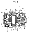
- Fig. 1 is a fragmentary cross section as viewed from above a power tool according to an embodiment of the present invention.
- Fig. 2 is an enlarged view of main portions of Fig. 1.
- Fig. 3 is a fragmentary cross section as viewed from a side of a power tool according to an embodiment of the invention.
- Fig. 4 is a cross-sectional view of a stator and a rotor according to an embodiment of the invention.
- Fig. 5 is a perspective view showing the outer appearances of a stator and a dustproof member according to an embodiment of the invention.
- Fig. 6 shows three views of a dustproof member according to an embodiment of the invention.
- the power tool comprises an outer frame portion 5 forming its outer contour, abatteryback (not shown) detachably mounted to the outer frame portion 5, an electric motor (not shown) rotated by electric power from the battery pack (not shown), a switch (not shown) mounted between the battery pack (not shown) and the motor (not shown) and controlling supply and stop of electric power to the motor (not shown), a drive portion (not shown) driven by rotation of the motor (not shown), and a tool (not shown) at the tip.
- the tool is detachably attached to the drive portion (not shown).
- the motor has a substantially cylindrical yoke 4A, a stator 4, a rotor 2, and a centrifugal fan 6 rigidly mounted to the rotor 2.
- the stator 4 has a substantially cylindrical yoke 4A and two permanent magnets 4C that are firmly mounted to the inner surface of the yoke and circumferentially spaced from each other by a first gap 4a.
- the rotor 2 is inserted inside the permanent magnets 4C at a second gap 4b radially.
- the stator 4 and rotor 2 are housed in the outer frame portion 5.
- the motor has carbon brushes 10 and a CB block 15.
- the brushes 10 are pressed against the commutator 2a of the rotor 2, providing rectification.
- the CB block 15 is made of a resin and shaped like a ring.
- the block has a hole (not shown) in its center.
- the rotor 2 is inserted in this hole.
- the CB block holds a CB tube 11, a CB cap 16, and lead wire (not shown).
- the CB tube is fabricated by stamping a metal sheet and slidably holds the carbon brushes 10.
- the CB cap 16 is made of a resin and screwed over the CB block 15, preventing the carbon brushes 10 from coming off.
- Ventilation holes 5a and 5b are formed in the outer frame portion 5.
- the ventilation holes 5a consist of plural holes arranged circumferentially of the centrifugal fan 6 in positions adjacent to the outer periphery of the centrifugal fan 6.
- the ventilation holes 5b consist of plural holes formed behind the CB block 15.
- a heat-dissipating plate 22 is mounted between the CB block 15 and the stator.
- the heat-dissipating plate 22 is shaped like an annular form by stamping a metal sheet.
- the heat-dissipating plate 22 has a rear end inserted in a recessed portion (not shown) of the CB block 15. The diameter of the plate increases in going forwardly from the rear end.
- the front end is shaped like a disk and attracted to the stator by magnetic force.
- the centrifugal fan 6 is firmly secured to the rotor 2 such that it is located ahead of the stator.
- the fan has a plurality of blades (not shown) protruding circumferentially. When the rotor 2 turns, centrifugal force is given to air present between the blades (not shown) of the centrifugal fan 6, so that the air flows radially toward the outside from inside.
- the flow passage for cooling wind is constructed as follows. Air flows in from the ventilation holes 5b acting as intake ports. The air flows through the hole portion (not shown) of the CB block 15, inside of the heat-dissipating plate 22, and gap between the stator and rotor 2. Centrifugal force is given by the centrifugal fan 6. The air is expelled from the ventilation holes 5a acting as vent ports.
- the dustproof member 19 will be described below.
- the dustproof member 19 is fabricated by stamping an iron sheet having a thickness of about 0.5 mm.
- the dustproof member 19 consists of a substantially cylindrical base portion 19a, two first protruding portions 19b extending axially forwardly from the outer periphery of the base portion 19a, a hole portion 19e formed such that the rotor 2 can pass through the hole portion, a second protruding portion 19c extending axially forwardly from the fringes of the hole portion 19e, and a third protruding portion 19d extending axially rearwardly from the outer periphery of the base portion 19a.
- the dustproof member 19 is made of iron and mounted in contact with the stator 4. Therefore, the dustproof member is magnetically excited by the magnetic force of the permanent magnets 4C. Accordingly, when iron powder 14 comes to the surroundings of the dustproof member 19, the iron powder 14 is attracted to the dustproof member 19.
- the first protruding portions 19b are mounted so as to be located between the ventilation holes 5a and the outer periphery of the centrifugal fan 6.
- the protruding portions are so mounted that when they are viewed from a direction substantially perpendicular to the ventillation holes 5a, the protruding portions partially overlap with the ventilation holes 5a.
- the first protruding portions 19b each assume a form like a flat plate extending perpendicularly to the radial direction of the stator 4. Accordingly, the iron powder 14 intruding from the ventilation holes 5a easily collides with the first protruding portions. Most of the iron powder 14 is attracted. Experiment using a structure having only the first protruding portions 19b has revealed that most of the iron powder 14 is attracted to or collides with the first protruding portions 19b, thus effectively preventing intrusion into the inside.
- the base portion 19a is similar in outside diameter with the yoke 4A and assumes a substantially disklike form.
- a hole portion 19e having an inside diameter substantially equal to the inside diameter of the permanent magnets 4C is formed in the center such that the rotor 2 can be inserted in the hole portion.
- the base portion 19a is mounted by magnetic force so as to substantially fully cover the end surface of the stator 4. Accordingly, if the iron powder 14 comes and intrudes without being attracted to the first protruding portions 19b, it is attracted to the base portion 19a. Furthermore, the base portion 19a almost completely plugs up the first gap 4a between the adjacent permanent magnets 4C and so the iron powder 14 does not readily intrude into the first gap 4a.
- the second protruding portion 19c is substantially cylindrical in shape, and extends axially forwardly from the fringes of the hole portion 19e having an inside diameter substantially equal to the inside diameter of the permanent magnets 4C.
- the second protruding portion is so mounted that a slight gap is formed between this portion and the centrifugal fan 6. Accordingly, if the iron powder 14 comes and intrudes without being attracted to the first protruding portions 19b or the base portion 19a, the powder is attracted to the second protruding portion 19c. Since the second protruding portion 19c projects over the whole periphery, intrusion of the iron powder 14 into the first gap 4a and second gap 4b can be prevented effectively.
- the dustproofing effect is enhanced by making the diameter of the second protruding portion 19c substantially equal to the inside diameter of the permanent magnets 4C.
- Experiment using a structure having only the second protruding portion 19c has shown that the iron powder 14 is mostly attracted to or collides with the second protruding portion 19c, effectively preventing intrusion into the inside.
- first protruding portions 19b, base portion 19a, and second protruding portion 19c are combined, a triple protection is provided. By combining these portions appropriately to have a single or double protection, dustproofing is provided. However, the dustproofing effect can be increased further by increasing the number of stages of protection to double and triple.
- the third protruding portion 19d is engaged in a recessed portion 4c formed in the yoke 4A. This places the dustproof member 19 and yoke 4A in position circumferentially.
- a convex portion (not shown) engaged in the recessed portion 4c is formed on the housing 5. This places the yoke 4A and housing 5 in position circumferentially.
- first protruding portions 19b are so mounted that they seem to overlap fully with the ventilation holes 5a when viewed substantially in a direction perpendicular to the ventilation holes 5a, the flow rate of the cooling wind decreases but the dustproofing is enhanced. If the first protruding portions 19b are so mounted that they seem to half overlap with the ventilation holes 5a, the flow rate of the cooling wind does not decrease so much, and a sufficient level of dustproofing is obtained. If the first protruding portions 19b are so mounted that they seem to overlap about ten percents of the ventilation holes 5a, the flow rate of the cooling wind hardly decreases. Also, dustproofing is obtained.
- the number of the first protruding portions 19b is not limited to two . Only one first protruding portionmaybe provided. Also, multiple first protruding portions may be provided. If more first protruding portions are provided, the dustproofing is enhanced further. In addition, if the first protruding portions 19b each assume a form of a flat plate substantially parallel to the radial direction of the stator 4, the flow rate of the cooling wind decreases little, though the dustproofing is deteriorated slightly.
- the first protruding portions 19b are made of a nonmagnetic material such as a plastic, the action of attracting the iron powder 14 is lost but slight dustproofing is obtained because the action of causing the iron powder 14 to collide is obtained.
- Another advantage of a second protruding portion 19c is that temperature rise of the rotor 2 that is a heat source can be suppressed effectively by throttling the flow passage and supplying a stream of air with higher velocity between the rotor 2 and the stator 4.
- the air passage can be made to have no unevenness.
- the cooling efficiency is improved by supplying a smooth stream of air.
Landscapes
- Engineering & Computer Science (AREA)
- Mechanical Engineering (AREA)
- Power Engineering (AREA)
- Motor Or Generator Cooling System (AREA)
- Motor Or Generator Frames (AREA)
- Portable Power Tools In General (AREA)
Abstract
Description
Claims (4)
- A power tool comprising:a stator having a substantially cylindrical yoke and a plurality of permanent magnets that are firmly fixed to an inner surface of the yoke and circumferentially spaced from each other by a first gap;a rotor inserted inside the permanent magnets at a second gap radially;an outer frame portion that accommodates the stator and the rotor;a ventilation hole formed in the outer frame portion to place the first and second gaps in communication with an atmosphere; anda dustproof member comprising a ferromagnetic material, which is mounted in contact with the stator and has a protruding portion located in a passage going from the first and second gaps to the atmosphere via the ventilation hole.
- The power tool according to claim 1, wherein the rotor has a centrifugal fan, and the protruding portion is located within the passage communicating with the atmosphere from the outer periphery of the centrifugal fan through the ventilation hole.
- The power tool according to claim 1, wherein the dustproof member has a hole portion through which the rotor can pass, and the protruding portion extends axially from an end surface of the hole portion.
- A power tool comprising:wherein the dustproof member is mounted so as to plug up the second gap at an end surface of the stator.a stator having a substantially cylindrical yoke and a plurality of permanent magnets that are firmly fixed to an inner surface of the yoke and circumferentially spaced from each other by a first gap;a rotor inserted inside the permanent magnets at a second gap radially;an outer frame portion that accommodates the stator and the rotor;a ventilation hole formed in the outer frame portion to place the first and second gaps in communication with an atmosphere; anda dustproof member comprising a ferromagnetic material and mounted in contact with the stator,
Applications Claiming Priority (2)
| Application Number | Priority Date | Filing Date | Title |
|---|---|---|---|
| JP2004068197A JP4301040B2 (en) | 2004-03-10 | 2004-03-10 | Electric tool |
| JP2004068197 | 2004-03-10 |
Publications (2)
| Publication Number | Publication Date |
|---|---|
| EP1575148A1 true EP1575148A1 (en) | 2005-09-14 |
| EP1575148B1 EP1575148B1 (en) | 2007-08-29 |
Family
ID=34824592
Family Applications (1)
| Application Number | Title | Priority Date | Filing Date |
|---|---|---|---|
| EP05005140A Expired - Lifetime EP1575148B1 (en) | 2004-03-10 | 2005-03-09 | Power tool |
Country Status (5)
| Country | Link |
|---|---|
| US (1) | US7375447B2 (en) |
| EP (1) | EP1575148B1 (en) |
| JP (1) | JP4301040B2 (en) |
| CN (1) | CN100396446C (en) |
| DE (1) | DE602005002163T2 (en) |
Cited By (2)
| Publication number | Priority date | Publication date | Assignee | Title |
|---|---|---|---|---|
| WO2008018611A1 (en) * | 2006-08-11 | 2008-02-14 | Hitachi Koki Co., Ltd. | Power tool |
| WO2007081033A3 (en) * | 2006-01-11 | 2008-06-19 | Hitachi Koki Kk | Electric tool |
Families Citing this family (12)
| Publication number | Priority date | Publication date | Assignee | Title |
|---|---|---|---|---|
| JP4692288B2 (en) * | 2006-01-11 | 2011-06-01 | 日立工機株式会社 | Electric tool and assembling method thereof |
| DE102008011589B3 (en) * | 2008-02-28 | 2009-04-09 | Metabowerke Gmbh | Electric hand tool with magnets to absorb dust |
| US8278774B2 (en) * | 2009-06-29 | 2012-10-02 | Pratt & Whitney Canada Corp. | Gas turbine with wired shaft forming part of a generator/motor assembly |
| US8097972B2 (en) * | 2009-06-29 | 2012-01-17 | Pratt & Whitney Canada Corp. | Gas turbine with magnetic shaft forming part of a generator/motor assembly |
| JP5829947B2 (en) * | 2012-02-22 | 2015-12-09 | 株式会社マキタ | Electric tool |
| JP5836876B2 (en) * | 2012-04-25 | 2015-12-24 | 株式会社マキタ | Electric tool |
| WO2014049245A1 (en) * | 2012-09-25 | 2014-04-03 | Valeo Equipements Electriques Moteur | Transmission assembly comprising an electric machine and two clutches |
| JP6281842B2 (en) * | 2014-02-18 | 2018-02-21 | パナソニックIpマネジメント株式会社 | Electric tool |
| CN104753254A (en) * | 2015-03-04 | 2015-07-01 | 苏州通润驱动设备股份有限公司 | Permanent magnet synchronous motor and screw rod compressor containing permanent magnet synchronous motor |
| US11338426B2 (en) | 2015-11-02 | 2022-05-24 | Black & Decker, Inc. | Cordless power cutter |
| GB2563624B (en) | 2017-06-20 | 2020-04-08 | Dyson Technology Ltd | A compressor |
| WO2025249049A1 (en) * | 2024-05-31 | 2025-12-04 | 工機ホールディングス株式会社 | Work machine |
Citations (4)
| Publication number | Priority date | Publication date | Assignee | Title |
|---|---|---|---|---|
| NL104930C (en) * | 1900-01-01 | |||
| DE2612364A1 (en) * | 1976-03-24 | 1977-09-29 | Licentia Gmbh | Stationary drive for tools and accessories - has air guiding device reversing cooling air direction of flow at motor commutator end |
| US20020182020A1 (en) * | 2001-03-02 | 2002-12-05 | Katsuhiro Oomori | Motor-driven tool |
| DE10203890A1 (en) * | 2002-01-28 | 2003-08-14 | Unique Product & Design Co | Direct current motor for operating with permanent magnets, has carbon brushes, front and rear covers, a stator with permanent magnets and a casing with stacked silicon steel plates for the magnets. |
Family Cites Families (8)
| Publication number | Priority date | Publication date | Assignee | Title |
|---|---|---|---|---|
| DE3539851A1 (en) * | 1985-11-09 | 1987-05-14 | Bosch Gmbh Robert | ELECTRICAL MACHINE, IN PARTICULAR FOR TURNING DEVICES OF INTERNAL COMBUSTION ENGINES |
| CN1051459C (en) | 1993-01-01 | 2000-04-19 | 殷劲 | Health-care medicament for rehabilitating function |
| JPH06284607A (en) * | 1993-03-26 | 1994-10-07 | Mitsubishi Electric Corp | Permanent magnet type rotating electric machine |
| JPH09149599A (en) * | 1995-11-27 | 1997-06-06 | Hitachi Ltd | Fully closed rotating electric machine |
| US5767596A (en) * | 1996-10-03 | 1998-06-16 | General Electric Company | Dynamoelectric machine and processes for making the same |
| JP3417332B2 (en) * | 1999-03-12 | 2003-06-16 | 株式会社デンソー | DC motor |
| JP3890970B2 (en) * | 2001-12-14 | 2007-03-07 | 日立工機株式会社 | Electric tool |
| JP3948371B2 (en) | 2002-08-21 | 2007-07-25 | 日立工機株式会社 | Electric tool |
-
2004
- 2004-03-10 JP JP2004068197A patent/JP4301040B2/en not_active Expired - Lifetime
-
2005
- 2005-03-08 US US11/073,758 patent/US7375447B2/en not_active Expired - Lifetime
- 2005-03-09 DE DE602005002163T patent/DE602005002163T2/en not_active Expired - Lifetime
- 2005-03-09 CN CNB2005100536221A patent/CN100396446C/en not_active Expired - Lifetime
- 2005-03-09 EP EP05005140A patent/EP1575148B1/en not_active Expired - Lifetime
Patent Citations (4)
| Publication number | Priority date | Publication date | Assignee | Title |
|---|---|---|---|---|
| NL104930C (en) * | 1900-01-01 | |||
| DE2612364A1 (en) * | 1976-03-24 | 1977-09-29 | Licentia Gmbh | Stationary drive for tools and accessories - has air guiding device reversing cooling air direction of flow at motor commutator end |
| US20020182020A1 (en) * | 2001-03-02 | 2002-12-05 | Katsuhiro Oomori | Motor-driven tool |
| DE10203890A1 (en) * | 2002-01-28 | 2003-08-14 | Unique Product & Design Co | Direct current motor for operating with permanent magnets, has carbon brushes, front and rear covers, a stator with permanent magnets and a casing with stacked silicon steel plates for the magnets. |
Cited By (2)
| Publication number | Priority date | Publication date | Assignee | Title |
|---|---|---|---|---|
| WO2007081033A3 (en) * | 2006-01-11 | 2008-06-19 | Hitachi Koki Kk | Electric tool |
| WO2008018611A1 (en) * | 2006-08-11 | 2008-02-14 | Hitachi Koki Co., Ltd. | Power tool |
Also Published As
| Publication number | Publication date |
|---|---|
| DE602005002163D1 (en) | 2007-10-11 |
| CN100396446C (en) | 2008-06-25 |
| US20050200215A1 (en) | 2005-09-15 |
| JP4301040B2 (en) | 2009-07-22 |
| US7375447B2 (en) | 2008-05-20 |
| CN1666845A (en) | 2005-09-14 |
| JP2005254376A (en) | 2005-09-22 |
| DE602005002163T2 (en) | 2008-05-21 |
| EP1575148B1 (en) | 2007-08-29 |
Similar Documents
| Publication | Publication Date | Title |
|---|---|---|
| US7375447B2 (en) | Power tool | |
| US6661148B2 (en) | Motor-driven tool | |
| US7166939B2 (en) | Electric hand tool | |
| JP6382122B2 (en) | Electric blower and vacuum cleaner equipped with the same | |
| US20110278970A1 (en) | Electric motor | |
| TWI584561B (en) | Motor with heat dissipation structure | |
| EP3043450B1 (en) | Motor with heat dissipation structure capable of restraining temperature therein | |
| EP3043455B1 (en) | Motor with heat dissipation structure | |
| TW201334374A (en) | Motor | |
| JP3307386B2 (en) | Electric blower and vacuum cleaner using the same | |
| US20050269884A1 (en) | Electric tool | |
| US6812608B2 (en) | Direct current motor having field magnets formed by injection molding synthetic resin, with which magnetic particles are mixed, to the inner periphery of the stator core | |
| WO2005027312A8 (en) | Electric machine and pump which uses said electric machine | |
| CN205141872U (en) | Permanent magnet brushless motor with dustproof construction | |
| JP2022148192A (en) | Electric blower and vacuum cleaner having the same | |
| JP6903036B2 (en) | Electric blower and vacuum cleaner equipped with it | |
| JP2025034604A (en) | Electric blower and vacuum cleaner equipped with same | |
| CN223487987U (en) | A dust-proof structure for a switched reluctance motor for an angle grinder | |
| JP7253746B2 (en) | Brushless motors and power tools | |
| JP5051430B2 (en) | Portable power tools | |
| CN216959531U (en) | Magnet protective housing of motor rotor | |
| JP4131644B2 (en) | Electric blower | |
| JP2001095203A (en) | Cooling structure for small-sized motor | |
| JP2008017645A (en) | Permanent magnet embedded motor | |
| JP2006315107A (en) | Electric tool |
Legal Events
| Date | Code | Title | Description |
|---|---|---|---|
| PUAI | Public reference made under article 153(3) epc to a published international application that has entered the european phase |
Free format text: ORIGINAL CODE: 0009012 |
|
| AK | Designated contracting states |
Kind code of ref document: A1 Designated state(s): AT BE BG CH CY CZ DE DK EE ES FI FR GB GR HU IE IS IT LI LT LU MC NL PL PT RO SE SI SK TR |
|
| AX | Request for extension of the european patent |
Extension state: AL BA HR LV MK YU |
|
| 17P | Request for examination filed |
Effective date: 20060116 |
|
| AKX | Designation fees paid |
Designated state(s): DE FR GB |
|
| 17Q | First examination report despatched |
Effective date: 20060704 |
|
| GRAP | Despatch of communication of intention to grant a patent |
Free format text: ORIGINAL CODE: EPIDOSNIGR1 |
|
| GRAS | Grant fee paid |
Free format text: ORIGINAL CODE: EPIDOSNIGR3 |
|
| GRAA | (expected) grant |
Free format text: ORIGINAL CODE: 0009210 |
|
| AK | Designated contracting states |
Kind code of ref document: B1 Designated state(s): DE FR GB |
|
| REG | Reference to a national code |
Ref country code: GB Ref legal event code: FG4D |
|
| REF | Corresponds to: |
Ref document number: 602005002163 Country of ref document: DE Date of ref document: 20071011 Kind code of ref document: P |
|
| ET | Fr: translation filed | ||
| PLBE | No opposition filed within time limit |
Free format text: ORIGINAL CODE: 0009261 |
|
| STAA | Information on the status of an ep patent application or granted ep patent |
Free format text: STATUS: NO OPPOSITION FILED WITHIN TIME LIMIT |
|
| 26N | No opposition filed |
Effective date: 20080530 |
|
| REG | Reference to a national code |
Ref country code: FR Ref legal event code: PLFP Year of fee payment: 12 |
|
| REG | Reference to a national code |
Ref country code: FR Ref legal event code: PLFP Year of fee payment: 13 |
|
| REG | Reference to a national code |
Ref country code: FR Ref legal event code: PLFP Year of fee payment: 14 |
|
| REG | Reference to a national code |
Ref country code: DE Ref legal event code: R082 Ref document number: 602005002163 Country of ref document: DE Representative=s name: HOFFMANN - EITLE PATENT- UND RECHTSANWAELTE PA, DE Ref country code: DE Ref legal event code: R081 Ref document number: 602005002163 Country of ref document: DE Owner name: KOKI HOLDINGS CO., LTD., JP Free format text: FORMER OWNER: HITACHI KOKI CO., LTD., TOKIO/TOKYO, JP |
|
| REG | Reference to a national code |
Ref country code: DE Ref legal event code: R084 Ref document number: 602005002163 Country of ref document: DE |
|
| REG | Reference to a national code |
Ref country code: GB Ref legal event code: 746 Effective date: 20181031 |
|
| PGFP | Annual fee paid to national office [announced via postgrant information from national office to epo] |
Ref country code: GB Payment date: 20220321 Year of fee payment: 18 |
|
| PGFP | Annual fee paid to national office [announced via postgrant information from national office to epo] |
Ref country code: FR Payment date: 20220322 Year of fee payment: 18 |
|
| GBPC | Gb: european patent ceased through non-payment of renewal fee |
Effective date: 20230309 |
|
| PG25 | Lapsed in a contracting state [announced via postgrant information from national office to epo] |
Ref country code: GB Free format text: LAPSE BECAUSE OF NON-PAYMENT OF DUE FEES Effective date: 20230309 |
|
| PG25 | Lapsed in a contracting state [announced via postgrant information from national office to epo] |
Ref country code: GB Free format text: LAPSE BECAUSE OF NON-PAYMENT OF DUE FEES Effective date: 20230309 Ref country code: FR Free format text: LAPSE BECAUSE OF NON-PAYMENT OF DUE FEES Effective date: 20230331 |
|
| PGFP | Annual fee paid to national office [announced via postgrant information from national office to epo] |
Ref country code: DE Payment date: 20240320 Year of fee payment: 20 |
|
| REG | Reference to a national code |
Ref country code: DE Ref legal event code: R071 Ref document number: 602005002163 Country of ref document: DE |