EP1575034A1 - Input sound processor - Google Patents
Input sound processor Download PDFInfo
- Publication number
- EP1575034A1 EP1575034A1 EP05004681A EP05004681A EP1575034A1 EP 1575034 A1 EP1575034 A1 EP 1575034A1 EP 05004681 A EP05004681 A EP 05004681A EP 05004681 A EP05004681 A EP 05004681A EP 1575034 A1 EP1575034 A1 EP 1575034A1
- Authority
- EP
- European Patent Office
- Prior art keywords
- power
- input sound
- frequency components
- frequency
- vowel
- Prior art date
- Legal status (The legal status is an assumption and is not a legal conclusion. Google has not performed a legal analysis and makes no representation as to the accuracy of the status listed.)
- Granted
Links
- 230000003044 adaptive effect Effects 0.000 claims description 18
- 230000005236 sound signal Effects 0.000 claims description 3
- 238000004364 calculation method Methods 0.000 description 30
- 238000003775 Density Functional Theory Methods 0.000 description 21
- 238000010586 diagram Methods 0.000 description 4
- 238000000034 method Methods 0.000 description 4
- 230000002238 attenuated effect Effects 0.000 description 1
- 230000000694 effects Effects 0.000 description 1
- 239000000284 extract Substances 0.000 description 1
- 239000000463 material Substances 0.000 description 1
- 238000012986 modification Methods 0.000 description 1
- 230000004048 modification Effects 0.000 description 1
Images

Classifications
-
- G—PHYSICS
- G10—MUSICAL INSTRUMENTS; ACOUSTICS
- G10L—SPEECH ANALYSIS TECHNIQUES OR SPEECH SYNTHESIS; SPEECH RECOGNITION; SPEECH OR VOICE PROCESSING TECHNIQUES; SPEECH OR AUDIO CODING OR DECODING
- G10L25/00—Speech or voice analysis techniques not restricted to a single one of groups G10L15/00 - G10L21/00
-
- G—PHYSICS
- G10—MUSICAL INSTRUMENTS; ACOUSTICS
- G10L—SPEECH ANALYSIS TECHNIQUES OR SPEECH SYNTHESIS; SPEECH RECOGNITION; SPEECH OR VOICE PROCESSING TECHNIQUES; SPEECH OR AUDIO CODING OR DECODING
- G10L21/00—Speech or voice signal processing techniques to produce another audible or non-audible signal, e.g. visual or tactile, in order to modify its quality or its intelligibility
- G10L21/02—Speech enhancement, e.g. noise reduction or echo cancellation
- G10L21/0316—Speech enhancement, e.g. noise reduction or echo cancellation by changing the amplitude
- G10L21/0364—Speech enhancement, e.g. noise reduction or echo cancellation by changing the amplitude for improving intelligibility
Definitions
- the present invention relates to an input sound processor for determining the sound power at a specific point, more specifically, to an input sound processor for estimation of the power of a guide voice at a microphone.
- a typical navigation voice corrector for use in a navigation system changes the sound pressure level of a guide voice depending upon the ambient noise level to provide an intelligible guide voice even in noisy environments (see, for example, Japanese Unexamined Patent Application Publication No. 11-166835 (pages 3 to 6, Figs. 1 to 10)).
- a loudness-compensation-based gain determining unit corrects for the gain of a guide voice output from a loudspeaker based on the sound pressure levels of ambient noise and the guide voice at the position of a microphone, which is assumed to be a listening point of the guide voice.
- the sound pressure level of the ambient noise and the guide voice input to the loudness-compensation-based gain determining unit is represented by total sound power which is determined by summing powers at all of a plurality of frequency components.
- the guide voice and the ambient noise actually reach the microphone at the same time, and it is not possible to extract only the guide voice from the sound collected by the microphone.
- One typical technique for extracting a guide voice is estimation of the guide voice at the microphone based on the transfer characteristic from the loudspeaker to the microphone and the guide voice signal input to the loudspeaker.
- the total power of the guide voice at the microphone is determined by separately determining power at each frequency component of the guide voice and a square amplitude of the transfer characteristic at each frequency component and performing a product-sum operation at each frequency component (see, for example, Japanese Unexamined Patent Application Publication No. 2002-23790 (pages 3 to 4, Figs. 1 to 2)).
- an input sound processor for estimation of total power of an input sound output from a loudspeaker at a microphone includes a first frequency analysis unit that divides an input sound signal input to the loudspeaker into a plurality of frequency components, a first power calculating unit that determines power at each of the frequency components divided by the first frequency analysis unit, a square amplitude calculating unit that determines a square amplitude of a filter coefficient at each of the frequency components, the filter coefficient being a filter characteristic corresponding to a transfer characteristic in an acoustic space from the loudspeaker to the microphone, a power comparing unit that compares the power at each of the frequency components determined by the first power calculating unit with a reference value, a multiplication point setting unit that sets multiplication points indicating frequency components at which the total power of the input sound is to be determined based on a comparison result of the power comparing unit, and a product-sum operation unit that performs a product-sum operation at the multiplication points set by the multiplication point setting unit
- the multiplication point setting unit sets frequency components other than a frequency component having power equal to or lower than the reference value as the multiplication points. This ensures that a frequency component having a small product of the power and the square amplitude of each filter coefficient, which thus does not affect the overall product-sum operation, can be extracted.
- the power comparing unit compares the power at each of the frequency components determined by the first power calculating unit with the reference value, and compares the square amplitude of the filter coefficient with the reference value.
- the multiplication point setting unit sets frequency components other than a frequency component having at least one of power and square amplitude equal to or lower than the reference value as the multiplication points.
- a sound having a specific frequency band may be absorbed, and the square amplitude of the filter characteristic at this frequency band is very low.
- the product of the square amplitude and the power has a small value. A product-sum operation is not performed at this frequency band, thus reducing the amount of processing of the overall product-sum operation.
- an input sound processor for estimation of total power of an input sound output from a loudspeaker at a microphone includes a first frequency analysis unit that divides an input sound signal input to the loudspeaker into a plurality of frequency components, a first power calculating unit that determines power at each of the frequency components divided by the first frequency analysis unit, a square amplitude calculating unit that determines a square amplitude of a filter coefficient at each of the frequency components, the filter coefficient being a filter characteristic corresponding to a transfer characteristic in an acoustic space from the loudspeaker to the microphone, a consonant or vowel determining unit that determines whether the input sound comprises a consonant or a vowel, a multiplication point setting unit that sets multiplication points indicating frequency components at which the total power of the input sound is to be determined based on a determination result of the consonant or vowel determining unit, and a product-sum operation unit that performs a product-sum operation at the multiplication points set
- the voice has large variations in the values of frequency components depending upon a consonant or a vowel. Specifically, if the voice is a composed of a consonant, the frequency components specific to the consonant have values, while the other frequency components have a value of substantially zero. If the voice is composed of a vowel, the frequency components specific to the vowel have values, while the other frequency components have a value of substantially zero.
- a frequency component having substantially no power can be identified, and a product-sum operation at this frequency component can be omitted. Therefore, the amount of processing can be reduced, and an inexpensive processor can be used, leading to cost saving.
- the consonant or vowel determining unit compares power at a vowel frequency range with power at a consonant frequency range to determine whether the input sound comprise a consonant or a vowel. It can therefore be easily determined whether the input sound is composed of a consonant or a vowel.
- the vowel frequency range is 100 Hz to 1 kHz
- the consonant frequency range is 1 kHz to 8 kHz. Since the vowel frequency range and the consonant frequency range do not overlap each other, the consonant or vowel determination can more easily be performed.
- the input sound process further includes a consonant-range power determining unit that determines the power at the consonant frequency range by summing powers at frequency components determined by the first power calculating unit, the frequency components being included in the consonant frequency range, and a vowel-range power determining unit that determines the power at the vowel frequency range by summing powers at frequency components determined by the first power calculating unit, the frequency components being included in the vowel frequency range.
- a consonant-range power determining unit that determines the power at the consonant frequency range by summing powers at frequency components determined by the first power calculating unit, the frequency components being included in the vowel frequency range.
- the input sound processor further includes an adaptive filter that determines the filter coefficient.
- the input sound processor further includes a second frequency analysis unit that divides a signal output from the microphone into a plurality of frequency components, wherein the adaptive filter determines the filter coefficient at each of the frequency components divided by the first frequency analysis unit and the frequency components divided by the second frequency analysis unit.
- the filter coefficient corresponding to the actual acoustic space can correctly be determined.
- the microphone collects sound including the input sound output from the loudspeaker and ambient noise. If ambient noise exists at the microphone position, the total power of the input sound can be determined without any effects of the ambient noise.
- the input sound processor further includes a total power determining unit that determines total power of the sound collected by the microphone, and a subtracting unit that subtracts the total power at the input sound at the microphone determined by the product-sum operation unit using the product-sum operation from the total power determined by the total power determining unit to determine total power of the ambient noise.
- a total power determining unit that determines total power of the sound collected by the microphone
- a subtracting unit that subtracts the total power at the input sound at the microphone determined by the product-sum operation unit using the product-sum operation from the total power determined by the total power determining unit to determine total power of the ambient noise.
- the input sound is preferably a guide voice output from an in-vehicle device.
- the total power of the guide voice output from the in-vehicle device can be determined, thus allowing gain control of the guide voice in a vehicle cabin having relatively high ambient noise.
- Fig. 1 is a block diagram of an input sound processor according to a first embodiment of the present invention.
- the input sound processor shown in Fig. 1 which is installed in a vehicle, estimates the power of a guide voice at the position of a microphone 100, and extracts ambient noise other than the guide voice from sound collected by the microphone 100 to determine the power of the noise.
- the input sound processor includes the microphone 100, discrete Fourier transform (DFT) calculation units 10 and 12, power calculation units 14 and 16, a total power determination unit 18, an adaptive filter 20, a square amplitude calculation unit 22, a product-sum operation unit 24, a power comparing unit 26, a multiplication point setting unit 28, and an adder 30.
- DFT discrete Fourier transform
- the DFT calculation unit 10 performs DFT on a signal output from the microphone 100 to extract the signal level at each frequency component.
- the input sound processor further includes an analog-to-digital converter before the DFT calculation unit 10 for converting the output signal from the microphone 100 into digital data, and the digital data is input to the DFT calculation unit 10.
- the DFT calculation unit 10 determines the signal levels at 1024 points into which the audible frequency bandwidth is divided.
- the microphone 100 is located at a predetermined position in the vehicle cabin, which is assumed to be a user's listening point, e.g., a certain point on the steering wheel.
- the power calculation unit 14 determines the power of the signal level at each frequency component determined by the DFT calculation unit 10. Specifically, the square of each of the real part and imaginary part of the signal output from the DFT calculation unit 10 is calculated and the squares are summed to determine the sound power at each frequency component.
- the total power determination unit 18 determines the total power of sound collected by the microphone 100 by summing the powers at frequency components determined by the power calculation unit 14.
- the DFT calculation unit 12 performs DFT on a guide voice signal input from a guide voice source 200 to extract the signal level at each frequency component.
- the input sound processor further includes an analog-to-digital converter before the DFT calculation unit 12, like the DFT calculation unit 10, for converting the guide voice signal output from the guide voice source 200 into digital data, which is then input to the DFT calculation unit 12.
- the DFT calculation unit 12 determines the signal levels at the same number (e.g., 1024) of frequency components as the frequency components handled by the DFT calculation unit 10.
- the guide voice source 200 is, for example, a navigation apparatus that outputs a signal corresponding to a guide voice, e.g., intersection guidance during route guidance. This guide voice is output from a loudspeaker (not shown) into the vehicle cabin, and reaches the microphone 100.
- the microphone 100 collects sound including the guide voice and various types of ambient noise, such as audio sound and road noise.
- the power calculation unit 16 determines the power of the signal level at each frequency component determined by the DFT calculation unit 12.
- the adaptive filter 20 identifies the transfer characteristic in the vehicle cabin from the loudspeaker from which the guide voice is output to the microphone 100 based on the output signals of the DFT calculation units 10 and 12.
- the guide voice output from the guide voice source 200 has first and second paths.
- the guide voice is output from the loudspeaker to the microphone 100 via the acoustic space of the vehicle cabin, and the corresponding signal is input to the DFT calculation unit 10.
- the guide voice signal is input directly to the DFT calculation unit 12.
- the first path includes the acoustic space of the vehicle cabin, and the second path does not include the acoustic space of the vehicle cabin. Therefore, an adaptive equalization performed based on the output signals of the DFT calculation units 10 and 12 allows for estimation of the transfer characteristic in the acoustic space of the vehicle cabin.
- the adaptive filter 20 outputs the transfer characteristic in terms of a filter coefficient (tap coefficient) allocated to each frequency component.
- the square amplitude calculation unit 22 determines a square amplitude value by calculating summing the square of each of the real part and imaginary part of each filter coefficient of the adaptive filter 20 and then calculating a sum of the squares.
- the power comparing unit 26 receives the power (P) at each frequency component of the guide voice from the power calculation unit 16, and also receives the square amplitude value (C) of the adaptive filter 20 at each frequency component from the square amplitude calculation unit 22.
- the power comparing unit 26 compares the values P and C with a reference value R. When a product-sum operation is performed at frequency component, if at least one of the values P and C is smaller than the reference value R or zero, the product of the values P and C becomes small. In this case, such a small value does not affect determination of the total power of the guide voice even if a product-sum operation is not performed on this value.
- the power comparing unit 26 determines whether or not the values P and C are equal to or smaller than the reference value R.
- voices including a guide voice
- a vowel includes frequency components ranging from 100 Hz to 1 kHz
- a consonant includes frequency components ranging from 1 kHz to 8 kHz.
- the vowel frequency range and the consonants frequency range differ from each other. If a guide voice is composed of a vowel, the signal level at the consonant frequency range is substantially zero, and power determined by the squared signal level is therefore substantially zero. If a guide voice is composed of a consonant, the signal level at the vowel frequency range is substantially zero, and the power P is therefore substantially zero.
- the value of the filter coefficient of the adaptive filter 20 at this frequency band and the square amplitude value C thereof are substantially zero.
- at least one of the values P and C is substantially zero (equal to or lower than the reference value R)
- a product-sum operation is not performed at this frequency band.
- the multiplication point setting unit 28 sets the frequency components other than a frequency component having at least one of the values P and C substantially zero (equal to or lower than the reference value R) as multiplication points at which a product-sum operation is to be performed.
- the product-sum operation unit 24 performs a product-sum operation. That is, the power P at each frequency component of the guide voice determined by the power calculation unit 16 is multiplied by the square amplitude value C of each filter coefficient of the adaptive filter 20 determined by the square amplitude calculation unit 22 at the same frequency component, and a sum of the products at the multiplication points set by the multiplication point setting unit 28 is calculated.
- the guide voice at the position of the microphone 100 is estimated using the adaptive filter 20, and the total power of the estimated guide voice is determined by the product-sum operation unit 24.
- the adder 30 subtracts the total power of the estimated guide voice at the microphone 100, which is output from the product-sum operation unit 24, from the total power of the sound collected by the microphone 100 including the guide voice and the ambient noise, which is determined by the total power determination unit 18. Thus, the total power of only the ambient noise collected by the microphone 100 is output from the adder 30.
- the DFT calculation unit 12 serves as a first frequency analysis unit
- the power calculation unit 16 serves as a first power calculating unit
- the square amplitude calculation unit 22 serves as a square amplitude calculating unit
- the power comparing unit 26 serves as a power comparing unit
- the multiplication point setting unit 28 serves as a multiplication point setting unit
- the product-sum operation unit 24 serves as a product-sum operation unit
- the DFT calculation unit 10 serves as a second frequency analysis unit.
- the DFT calculation unit 10, the power calculation unit 14, and the total power determination unit 18 serve as a total power determining unit
- the adder 30 serves as a subtracting unit.
- a product-sum operation is not performed at all frequency components, but is performed only at the frequency component having an effective value. That is, a product-sum operation is not to be performed at the frequency component having substantially no power. Therefore, the amount of processing is reduced, and an inexpensive processor may be used, leading to cost saving.
- a sound having a specific frequency band may be absorbed, and the square amplitude of the filter characteristic at this frequency band is very low.
- the product of the square amplitude and the power has a small value.
- a product-sum operation is not performed at this frequency band, thereby reducing the amount of processing of the overall product-sum operation.
- the filter coefficient is determined using the adaptive filter 20.
- the filter coefficient corresponding to the actual acoustic space can correctly be determined.
- the adder 30 subtracts the total power of the guide voice at the microphone 100 from the total power of the signal output from the microphone 100 to determine the total power of the ambient noise that does not include the guide voice.
- the gain of the guide voice can be determined using loudness compensation, thus providing an intelligible guide voice in a vehicle cabin having relatively high ambient noise.
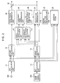
- Fig. 2 is a block diagram of an input sound processor according to a second embodiment of the present invention.
- the input sound processor shown in Fig. 2 includes a microphone 100, DFT operation units 10 and 12, power calculation units 14 and 16, a total power determination unit 18, an adaptive filter 20, a square amplitude calculation unit 22, a product-sum operation unit 24, a vowel-range power calculation unit 40, a consonant-range power calculation unit 42, a consonant/vowel determination unit 44, a multiplication point setting unit 46, and an adder 30.
- the input sound processor shown in Fig. 2 is provided with the vowel-range power calculation unit 40, the consonant-range power calculation unit 42, the consonant/vowel determination unit 44, and the multiplication point setting unit 46.
- the vowel-range power calculation unit 40 determines the power at the vowel frequency range (hereinafter referred to as vowel-range power) by summing powers at frequency components included in the vowel frequency range.
- the consonant-range power calculation unit 42 determines the power at the consonant frequency range (hereinafter referred to as a consonant-range power) by summing powers at frequency components included in the consonant frequency range.
- the vowel-range power and the consonant-range power may not be determined at all of the corresponding frequency ranges.
- the vowel-range power may be determined by summing powers at some of the vowel frequency range, and the consonant-range power may be determined by summing powers at some of the consonant frequency range.
- the consonant/vowel determination unit 44 compares the vowel-range power determined by the vowel-range power calculation unit 40 with the consonant-range power determined by the consonant-range power calculation unit 42 to determine whether the guide voice input from the guide voice source 200 is composed of a vowel or a consonant.
- the guide voice is composed of exclusively a vowel or a consonant, and it can be easily determined whether the guide voice at the present time is composed of a vowel or a consonant by comparing the vowel-range power with the consonant-range power.
- the multiplication point setting unit 46 sets the frequency components included in the vowel frequency range as multiplication points at which a product-sum operation is to be performed. If the consonant/vowel determination unit 44 determines that the guide voice is composed of a consonant, the multiplication point setting unit 46 sets the frequency components included in the consonant frequency range as multiplication points at which a product-sum operation is to be performed.
- the product-sum operation unit 24 performs a product-sum operation. That is, the power at each frequency component of the guide voice determined by the power calculation unit 16 is multiplied by the square amplitude of each filter coefficient of the adaptive filter 20 determined by the square amplitude calculation unit 22 at the same frequency component, and a sum of the products at the multiplication points set by the multiplication point setting unit 46 is calculated.
- the guide voice at the position of the microphone 100 is estimated using the adaptive filter 20, and the total power of the estimated guide voice is determined by the product-sum operation unit 24.
- the multiplication point setting unit 46 serves as a multiplication point setting unit
- the consonant/vowel determination unit 44 serves as a consonant or vowel determining unit
- the vowel-range power calculation unit 40 serves as a vowel-range power determining unit
- the consonant-range power calculation unit 42 serves as a consonant-range power determining unit.
- the guide voice has large variations in the values of frequency components depending upon a consonant or a vowel. Specifically, if the guide voice is composed of a consonant, the frequency components specific to the consonant have values, while the other frequency components have a value of substantially zero. If the guide voice is composed of a vowel, the frequency components specific to the vowel have values, while the other frequency components have a value of substantially zero.
- a frequency component having substantially no power can be identified, and a product-sum operation at this frequency component can be omitted. Therefore, the amount of processing can be reduced, and an inexpensive processor can be used, leading to cost saving.
- the present invention is not limited to the illustrated embodiments, and a variety of modifications may be made without departing from the scope of the present invention. While the power of a guide voice output from the guide voice source 200 is estimated in the illustrated embodiments, the total power of any other sound at the microphone position may be estimated. The present invention may be applied to estimation of sound power for a broadcast output from a radio receiver or the like.
- an audio device may be used in place of the guide voice source 200, and the total power of audio sound or the like at the microphone 100 may be estimated.
- the DFT calculation units 10 and 12 are used to divide an input signal into frequency components.
- any other method such as a filter bank method, may be used to divide an input signal into frequency components.
Landscapes
- Engineering & Computer Science (AREA)
- Computational Linguistics (AREA)
- Signal Processing (AREA)
- Health & Medical Sciences (AREA)
- Audiology, Speech & Language Pathology (AREA)
- Human Computer Interaction (AREA)
- Physics & Mathematics (AREA)
- Acoustics & Sound (AREA)
- Multimedia (AREA)
- Quality & Reliability (AREA)
- Circuit For Audible Band Transducer (AREA)
- Fittings On The Vehicle Exterior For Carrying Loads, And Devices For Holding Or Mounting Articles (AREA)
Abstract
Description
- The present invention relates to an input sound processor for determining the sound power at a specific point, more specifically, to an input sound processor for estimation of the power of a guide voice at a microphone.
- A typical navigation voice corrector for use in a navigation system changes the sound pressure level of a guide voice depending upon the ambient noise level to provide an intelligible guide voice even in noisy environments (see, for example, Japanese Unexamined Patent Application Publication No. 11-166835 (pages 3 to 6, Figs. 1 to 10)). In this navigation voice corrector, a loudness-compensation-based gain determining unit corrects for the gain of a guide voice output from a loudspeaker based on the sound pressure levels of ambient noise and the guide voice at the position of a microphone, which is assumed to be a listening point of the guide voice. The sound pressure level of the ambient noise and the guide voice input to the loudness-compensation-based gain determining unit is represented by total sound power which is determined by summing powers at all of a plurality of frequency components.
- However, the guide voice and the ambient noise actually reach the microphone at the same time, and it is not possible to extract only the guide voice from the sound collected by the microphone.
- One typical technique for extracting a guide voice is estimation of the guide voice at the microphone based on the transfer characteristic from the loudspeaker to the microphone and the guide voice signal input to the loudspeaker. The total power of the guide voice at the microphone is determined by separately determining power at each frequency component of the guide voice and a square amplitude of the transfer characteristic at each frequency component and performing a product-sum operation at each frequency component (see, for example, Japanese Unexamined Patent Application Publication No. 2002-23790 (pages 3 to 4, Figs. 1 to 2)).
- The latter publication discloses that the power determined at each frequency component of an input voice is multiplied by the square amplitude of each tap coefficient indicating the transfer characteristic and a sum of the products is then calculated. It is therefore necessary to perform a product-sum operation at all frequency components, resulting in a large amount of processing. A high-performance processor is therefore required, which is costly.
- Accordingly, it is an object of the present invention to provide a low-cost input sound processor with a small amount of processing.
- In one aspect of the present invention, an input sound processor for estimation of total power of an input sound output from a loudspeaker at a microphone includes a first frequency analysis unit that divides an input sound signal input to the loudspeaker into a plurality of frequency components, a first power calculating unit that determines power at each of the frequency components divided by the first frequency analysis unit, a square amplitude calculating unit that determines a square amplitude of a filter coefficient at each of the frequency components, the filter coefficient being a filter characteristic corresponding to a transfer characteristic in an acoustic space from the loudspeaker to the microphone, a power comparing unit that compares the power at each of the frequency components determined by the first power calculating unit with a reference value, a multiplication point setting unit that sets multiplication points indicating frequency components at which the total power of the input sound is to be determined based on a comparison result of the power comparing unit, and a product-sum operation unit that performs a product-sum operation at the multiplication points set by the multiplication point setting unit using the power at each of the frequency components determined by the first power calculating unit and the square amplitude of the filter coefficient at each of the frequency components determined by the square amplitude calculating unit. Thus, a product-sum operation is not performed at a frequency component having substantially no power. Therefore, the amount of processing can be reduced, and an inexpensive processor can be used, leading to cost saving.
- Preferably, the multiplication point setting unit sets frequency components other than a frequency component having power equal to or lower than the reference value as the multiplication points. This ensures that a frequency component having a small product of the power and the square amplitude of each filter coefficient, which thus does not affect the overall product-sum operation, can be extracted.
- Preferably, the power comparing unit compares the power at each of the frequency components determined by the first power calculating unit with the reference value, and compares the square amplitude of the filter coefficient with the reference value. Preferably, the multiplication point setting unit sets frequency components other than a frequency component having at least one of power and square amplitude equal to or lower than the reference value as the multiplication points. In view of the transfer characteristic in the acoustic space from the loudspeaker to the microphone, in particular, the transfer characteristic in the space of a vehicle cabin, a sound having a specific frequency band may be absorbed, and the square amplitude of the filter characteristic at this frequency band is very low. Thus, the product of the square amplitude and the power has a small value. A product-sum operation is not performed at this frequency band, thus reducing the amount of processing of the overall product-sum operation.
- In another aspect of the present invention, an input sound processor for estimation of total power of an input sound output from a loudspeaker at a microphone includes a first frequency analysis unit that divides an input sound signal input to the loudspeaker into a plurality of frequency components, a first power calculating unit that determines power at each of the frequency components divided by the first frequency analysis unit, a square amplitude calculating unit that determines a square amplitude of a filter coefficient at each of the frequency components, the filter coefficient being a filter characteristic corresponding to a transfer characteristic in an acoustic space from the loudspeaker to the microphone, a consonant or vowel determining unit that determines whether the input sound comprises a consonant or a vowel, a multiplication point setting unit that sets multiplication points indicating frequency components at which the total power of the input sound is to be determined based on a determination result of the consonant or vowel determining unit, and a product-sum operation unit that performs a product-sum operation at the multiplication points set by the multiplication point setting unit using the power at each of the frequency components determined by the first power calculating unit and the square amplitude of the filter coefficient at each of the frequency components determined by the square amplitude calculating unit.
- If the input sound is a voice, the voice has large variations in the values of frequency components depending upon a consonant or a vowel. Specifically, if the voice is a composed of a consonant, the frequency components specific to the consonant have values, while the other frequency components have a value of substantially zero. If the voice is composed of a vowel, the frequency components specific to the vowel have values, while the other frequency components have a value of substantially zero. By determining whether the input sound is composed of a vowel or a consonant, a frequency component having substantially no power can be identified, and a product-sum operation at this frequency component can be omitted. Therefore, the amount of processing can be reduced, and an inexpensive processor can be used, leading to cost saving.
- Preferably, the consonant or vowel determining unit compares power at a vowel frequency range with power at a consonant frequency range to determine whether the input sound comprise a consonant or a vowel. It can therefore be easily determined whether the input sound is composed of a consonant or a vowel.
- Preferably, the vowel frequency range is 100 Hz to 1 kHz, and the consonant frequency range is 1 kHz to 8 kHz. Since the vowel frequency range and the consonant frequency range do not overlap each other, the consonant or vowel determination can more easily be performed.
- Preferably, the input sound process further includes a consonant-range power determining unit that determines the power at the consonant frequency range by summing powers at frequency components determined by the first power calculating unit, the frequency components being included in the consonant frequency range, and a vowel-range power determining unit that determines the power at the vowel frequency range by summing powers at frequency components determined by the first power calculating unit, the frequency components being included in the vowel frequency range. Thus, the power at the consonant frequency range and the power at the vowel frequency range can be easily determined.
- Preferably, the input sound processor further includes an adaptive filter that determines the filter coefficient. Preferably, the input sound processor further includes a second frequency analysis unit that divides a signal output from the microphone into a plurality of frequency components, wherein the adaptive filter determines the filter coefficient at each of the frequency components divided by the first frequency analysis unit and the frequency components divided by the second frequency analysis unit. Thus, the filter coefficient corresponding to the actual acoustic space can correctly be determined.
- Preferably, the microphone collects sound including the input sound output from the loudspeaker and ambient noise. If ambient noise exists at the microphone position, the total power of the input sound can be determined without any effects of the ambient noise.
- Preferably, the input sound processor further includes a total power determining unit that determines total power of the sound collected by the microphone, and a subtracting unit that subtracts the total power at the input sound at the microphone determined by the product-sum operation unit using the product-sum operation from the total power determined by the total power determining unit to determine total power of the ambient noise. Thus, not only the total power of an input sound at the microphone position but also the total power of ambient noise, which does not include the input sound, can be determined.
- The input sound is preferably a guide voice output from an in-vehicle device. The total power of the guide voice output from the in-vehicle device can be determined, thus allowing gain control of the guide voice in a vehicle cabin having relatively high ambient noise.
-
- Fig. 1 is a block diagram of an input sound processor according to a first embodiment of the present invention; and
- Fig. 2 is a block diagram of an input sound processor according to a second embodiment of the present invention.
-
- An input sound processor according to embodiments of the present invention will now be described with reference to the drawings.
- Fig. 1 is a block diagram of an input sound processor according to a first embodiment of the present invention. The input sound processor shown in Fig. 1, which is installed in a vehicle, estimates the power of a guide voice at the position of a
microphone 100, and extracts ambient noise other than the guide voice from sound collected by themicrophone 100 to determine the power of the noise. - The input sound processor according to the first embodiment includes the
microphone 100, discrete Fourier transform (DFT)calculation units power calculation units power determination unit 18, anadaptive filter 20, a squareamplitude calculation unit 22, a product-sum operation unit 24, apower comparing unit 26, a multiplicationpoint setting unit 28, and anadder 30. - The DFT
calculation unit 10 performs DFT on a signal output from themicrophone 100 to extract the signal level at each frequency component. The input sound processor further includes an analog-to-digital converter before theDFT calculation unit 10 for converting the output signal from themicrophone 100 into digital data, and the digital data is input to theDFT calculation unit 10. For example, theDFT calculation unit 10 determines the signal levels at 1024 points into which the audible frequency bandwidth is divided. Themicrophone 100 is located at a predetermined position in the vehicle cabin, which is assumed to be a user's listening point, e.g., a certain point on the steering wheel. - The
power calculation unit 14 determines the power of the signal level at each frequency component determined by theDFT calculation unit 10. Specifically, the square of each of the real part and imaginary part of the signal output from theDFT calculation unit 10 is calculated and the squares are summed to determine the sound power at each frequency component. The totalpower determination unit 18 determines the total power of sound collected by themicrophone 100 by summing the powers at frequency components determined by thepower calculation unit 14. - The DFT
calculation unit 12 performs DFT on a guide voice signal input from aguide voice source 200 to extract the signal level at each frequency component. The input sound processor further includes an analog-to-digital converter before theDFT calculation unit 12, like theDFT calculation unit 10, for converting the guide voice signal output from theguide voice source 200 into digital data, which is then input to theDFT calculation unit 12. TheDFT calculation unit 12 determines the signal levels at the same number (e.g., 1024) of frequency components as the frequency components handled by theDFT calculation unit 10. Theguide voice source 200 is, for example, a navigation apparatus that outputs a signal corresponding to a guide voice, e.g., intersection guidance during route guidance. This guide voice is output from a loudspeaker (not shown) into the vehicle cabin, and reaches themicrophone 100. Themicrophone 100 collects sound including the guide voice and various types of ambient noise, such as audio sound and road noise. - The
power calculation unit 16 determines the power of the signal level at each frequency component determined by theDFT calculation unit 12. Theadaptive filter 20 identifies the transfer characteristic in the vehicle cabin from the loudspeaker from which the guide voice is output to themicrophone 100 based on the output signals of theDFT calculation units - As described above, the guide voice output from the
guide voice source 200 has first and second paths. In the first path, the guide voice is output from the loudspeaker to themicrophone 100 via the acoustic space of the vehicle cabin, and the corresponding signal is input to theDFT calculation unit 10. In the second path, the guide voice signal is input directly to theDFT calculation unit 12. The first path includes the acoustic space of the vehicle cabin, and the second path does not include the acoustic space of the vehicle cabin. Therefore, an adaptive equalization performed based on the output signals of theDFT calculation units adaptive filter 20 outputs the transfer characteristic in terms of a filter coefficient (tap coefficient) allocated to each frequency component. The squareamplitude calculation unit 22 determines a square amplitude value by calculating summing the square of each of the real part and imaginary part of each filter coefficient of theadaptive filter 20 and then calculating a sum of the squares. - The
power comparing unit 26 receives the power (P) at each frequency component of the guide voice from thepower calculation unit 16, and also receives the square amplitude value (C) of theadaptive filter 20 at each frequency component from the squareamplitude calculation unit 22. Thepower comparing unit 26 compares the values P and C with a reference value R. When a product-sum operation is performed at frequency component, if at least one of the values P and C is smaller than the reference value R or zero, the product of the values P and C becomes small. In this case, such a small value does not affect determination of the total power of the guide voice even if a product-sum operation is not performed on this value. Thepower comparing unit 26 determines whether or not the values P and C are equal to or smaller than the reference value R. - Generally, voices, including a guide voice, are composed of vowels and consonants. A vowel includes frequency components ranging from 100 Hz to 1 kHz, and a consonant includes frequency components ranging from 1 kHz to 8 kHz. The vowel frequency range and the consonants frequency range differ from each other. If a guide voice is composed of a vowel, the signal level at the consonant frequency range is substantially zero, and power determined by the squared signal level is therefore substantially zero. If a guide voice is composed of a consonant, the signal level at the vowel frequency range is substantially zero, and the power P is therefore substantially zero.
- In view of the transfer characteristic in the space of the vehicle cabin, if the signal level is greatly attenuated at a specific frequency band, e.g., when a sound having a specific frequency does not sufficiently propagate because it may be absorbed depending upon the shape of the vehicle cabin or the material of the seats in the vehicle cabin, the value of the filter coefficient of the
adaptive filter 20 at this frequency band and the square amplitude value C thereof are substantially zero. Thus, if at least one of the values P and C is substantially zero (equal to or lower than the reference value R), a product-sum operation is not performed at this frequency band. - Based on the result of the
power comparing unit 26, the multiplicationpoint setting unit 28 sets the frequency components other than a frequency component having at least one of the values P and C substantially zero (equal to or lower than the reference value R) as multiplication points at which a product-sum operation is to be performed. - The product-
sum operation unit 24 performs a product-sum operation. That is, the power P at each frequency component of the guide voice determined by thepower calculation unit 16 is multiplied by the square amplitude value C of each filter coefficient of theadaptive filter 20 determined by the squareamplitude calculation unit 22 at the same frequency component, and a sum of the products at the multiplication points set by the multiplicationpoint setting unit 28 is calculated. Thus, the guide voice at the position of themicrophone 100 is estimated using theadaptive filter 20, and the total power of the estimated guide voice is determined by the product-sum operation unit 24. - The
adder 30 subtracts the total power of the estimated guide voice at themicrophone 100, which is output from the product-sum operation unit 24, from the total power of the sound collected by themicrophone 100 including the guide voice and the ambient noise, which is determined by the totalpower determination unit 18. Thus, the total power of only the ambient noise collected by themicrophone 100 is output from theadder 30. - The reference value R is determined so that the total power of the estimated guide voice output from the product-
sum operation unit 24 has an error lower than a predetermined value. For example, the reference value R is determined so that the error is equal to or lower than 5 dB if the maximum power at each frequency component of the guide voice output from thepower calculation unit 16 or the maximum square amplitude of each filter coefficient of theadaptive filter 20 output from the squareamplitude calculation unit 22 is 2M. For example, if M = 16, R = 398 is obtained. - The
DFT calculation unit 12 serves as a first frequency analysis unit, thepower calculation unit 16 serves as a first power calculating unit, the squareamplitude calculation unit 22 serves as a square amplitude calculating unit, thepower comparing unit 26 serves as a power comparing unit, the multiplicationpoint setting unit 28 serves as a multiplication point setting unit, the product-sum operation unit 24 serves as a product-sum operation unit, and theDFT calculation unit 10 serves as a second frequency analysis unit. TheDFT calculation unit 10, thepower calculation unit 14, and the totalpower determination unit 18 serve as a total power determining unit, and theadder 30 serves as a subtracting unit. - Accordingly, a product-sum operation is not performed at all frequency components, but is performed only at the frequency component having an effective value. That is, a product-sum operation is not to be performed at the frequency component having substantially no power. Therefore, the amount of processing is reduced, and an inexpensive processor may be used, leading to cost saving.
- In view of the transfer characteristic in the acoustic space from the loudspeaker to the
microphone 100, in particular, the transfer characteristic in the space of the vehicle cabin, a sound having a specific frequency band may be absorbed, and the square amplitude of the filter characteristic at this frequency band is very low. Thus, the product of the square amplitude and the power has a small value. A product-sum operation is not performed at this frequency band, thereby reducing the amount of processing of the overall product-sum operation. - The filter coefficient is determined using the
adaptive filter 20. Thus, the filter coefficient corresponding to the actual acoustic space can correctly be determined. - The
adder 30 subtracts the total power of the guide voice at themicrophone 100 from the total power of the signal output from themicrophone 100 to determine the total power of the ambient noise that does not include the guide voice. Thus, the gain of the guide voice can be determined using loudness compensation, thus providing an intelligible guide voice in a vehicle cabin having relatively high ambient noise. Second Embodiment - Fig. 2 is a block diagram of an input sound processor according to a second embodiment of the present invention. The input sound processor shown in Fig. 2 includes a
microphone 100,DFT operation units power calculation units power determination unit 18, anadaptive filter 20, a squareamplitude calculation unit 22, a product-sum operation unit 24, a vowel-rangepower calculation unit 40, a consonant-rangepower calculation unit 42, a consonant/vowel determination unit 44, a multiplicationpoint setting unit 46, and anadder 30. In place of thepower comparing unit 26 and the multiplicationpoint setting unit 28 of the input sound processor shown in Fig. 1, the input sound processor shown in Fig. 2 is provided with the vowel-rangepower calculation unit 40, the consonant-rangepower calculation unit 42, the consonant/vowel determination unit 44, and the multiplicationpoint setting unit 46. - The vowel-range
power calculation unit 40 determines the power at the vowel frequency range (hereinafter referred to as vowel-range power) by summing powers at frequency components included in the vowel frequency range. The consonant-rangepower calculation unit 42 determines the power at the consonant frequency range (hereinafter referred to as a consonant-range power) by summing powers at frequency components included in the consonant frequency range. The vowel-range power and the consonant-range power may not be determined at all of the corresponding frequency ranges. The vowel-range power may be determined by summing powers at some of the vowel frequency range, and the consonant-range power may be determined by summing powers at some of the consonant frequency range. - The consonant/
vowel determination unit 44 compares the vowel-range power determined by the vowel-rangepower calculation unit 40 with the consonant-range power determined by the consonant-rangepower calculation unit 42 to determine whether the guide voice input from theguide voice source 200 is composed of a vowel or a consonant. As described above, the guide voice is composed of exclusively a vowel or a consonant, and it can be easily determined whether the guide voice at the present time is composed of a vowel or a consonant by comparing the vowel-range power with the consonant-range power. - If the consonant/
vowel determination unit 44 determines that the guide voice is composed of a vowel, the multiplicationpoint setting unit 46 sets the frequency components included in the vowel frequency range as multiplication points at which a product-sum operation is to be performed. If the consonant/vowel determination unit 44 determines that the guide voice is composed of a consonant, the multiplicationpoint setting unit 46 sets the frequency components included in the consonant frequency range as multiplication points at which a product-sum operation is to be performed. - The product-
sum operation unit 24 performs a product-sum operation. That is, the power at each frequency component of the guide voice determined by thepower calculation unit 16 is multiplied by the square amplitude of each filter coefficient of theadaptive filter 20 determined by the squareamplitude calculation unit 22 at the same frequency component, and a sum of the products at the multiplication points set by the multiplicationpoint setting unit 46 is calculated. Thus, the guide voice at the position of themicrophone 100 is estimated using theadaptive filter 20, and the total power of the estimated guide voice is determined by the product-sum operation unit 24. - The multiplication
point setting unit 46 serves as a multiplication point setting unit, the consonant/vowel determination unit 44 serves as a consonant or vowel determining unit, the vowel-rangepower calculation unit 40 serves as a vowel-range power determining unit, and the consonant-rangepower calculation unit 42 serves as a consonant-range power determining unit. - The guide voice has large variations in the values of frequency components depending upon a consonant or a vowel. Specifically, if the guide voice is composed of a consonant, the frequency components specific to the consonant have values, while the other frequency components have a value of substantially zero. If the guide voice is composed of a vowel, the frequency components specific to the vowel have values, while the other frequency components have a value of substantially zero. By determining whether the guide voice is composed of a vowel or a consonant, a frequency component having substantially no power can be identified, and a product-sum operation at this frequency component can be omitted. Therefore, the amount of processing can be reduced, and an inexpensive processor can be used, leading to cost saving.
- The present invention is not limited to the illustrated embodiments, and a variety of modifications may be made without departing from the scope of the present invention. While the power of a guide voice output from the
guide voice source 200 is estimated in the illustrated embodiments, the total power of any other sound at the microphone position may be estimated. The present invention may be applied to estimation of sound power for a broadcast output from a radio receiver or the like. - In the first embodiment, an audio device may be used in place of the
guide voice source 200, and the total power of audio sound or the like at themicrophone 100 may be estimated. - In the illustrated embodiments, the
DFT calculation units
Claims (12)
- An input sound processor for estimation of total power of an input sound output from a loudspeaker at a microphone (100), comprising:first frequency analysis means (12) for dividing an input sound signal input to the loudspeaker into a plurality of frequency components;first power calculating means (16) for determining power at each of the frequency components divided by the first frequency analysis means;square amplitude calculating means (22) for determining a square amplitude of a filter coefficient at each of the frequency components, the filter coefficient comprising a filter characteristic corresponding to a transfer characteristic of an acoustic space from the loudspeaker to the microphone;power comparing means (26) for comparing the power (P) at each of the frequency components determined by the first power calculating means with a reference value (R);multiplication point setting means (28) for setting multiplication points indicating frequency components at which the total power of the input sound is to be determined based on a comparison result of the power comparing means; andproduct-sum operation means (24) for performing a product-sum operation at the multiplication points set by the multiplication point setting means using the power at each of the frequency components determined by the first power calculating means and the square amplitude of the filter coefficient at each of the frequency components determined by the square amplitude calculating means.
- The input sound processor according to Claim 1,
wherein the multiplication point setting means sets frequency components other than a frequency component having power (P) equal to or lower than the reference value (R) as the multiplication points. - The input sound processor according to Claim 1,
wherein the power comparing means compares the power (P) at each of the frequency components determined by the first power calculating means with the reference value (R), ad compares the square amplitude (C) of the filter coefficient with the reference value (R), and
the multiplication point setting means sets frequency components other than a frequency component having at least one of power (P) and square amplitude (C) equal to or lower than the reference value (R) as the multiplication points. - The input sound processor according to Claim 1, further comprising:consonant or vowel determining means (44) for determining whether the input sound comprise a consonant or a vowel;multiplication point setting means (46) for setting multiplication points indicating frequency components at which the total power of the input sound is to be determined based on a determination result of the consonant or vowel determining means; andproduct-sum operation means (24) for performing a product-sum operation at the multiplication points set by the multiplication point setting means using the power at each of the frequency components determined by the first power calculating means and the square amplitude of the filter coefficient at each of the frequency components determined by the square amplitude calculating means.
- The input sound processor according to Claim 4,
wherein the consonant or vowel determining means compares power at a vowel frequency range with power at a consonant frequency range to determine whether the input sound comprises a consonant or a vowel. - The input sound processor according to Claim 5,
wherein the vowel frequency range is 100 Hz to 1 kHz, and the consonant frequency range is 1 kHz to 8 kHz. - The input sound processor according to Claim 5 or 6, further comprising:consonant-range power determining means (42) for determining the power at the consonant frequency range by summing powers at frequency components determined by the first power calculating means, the frequency components being included in the consonant frequency range; andvowel-range power determining means (40) for determining the power at the vowel frequency range by summing powers at frequency components determined by the first power calculating means, the frequency components being included in the vowel frequency range.
- The input sound processor according to any one of Claims 1 to 7, further comprising an adaptive filter (20) that determines the filter coefficient.
- The input sound processor according to Claim 8, further comprising second frequency analysis means (10) for dividing a signal output from the microphone into a plurality of frequency components,
wherein the adaptive filter determines the filter coefficient at each of the frequency components divided by the first frequency analysis means and the frequency components divided by the second frequency analysis means. - The input sound processor according to Claim 9,
wherein the microphone collects sound including the input sound output from the loudspeaker and ambient noise. - The input sound processor according to Claim 10, further comprising:total power determining means (10, 14, 18) for determining total power of the sound collected by the microphone; andsubtracting means (30) for subtracting the total sound power of the input sound at the microphone determined by the product-sum operation means using the product-sum operation from the total power determined by the total power determining means to determine total power of the ambient noise.
- The input sound processor according to any one of Claims 1 to 11, wherein the input sound comprises a guide voice output from an in-vehicle device.
Applications Claiming Priority (2)
| Application Number | Priority Date | Filing Date | Title |
|---|---|---|---|
| JP2004063294A JP4235128B2 (en) | 2004-03-08 | 2004-03-08 | Input sound processor |
| JP2004063294 | 2004-03-08 |
Publications (2)
| Publication Number | Publication Date |
|---|---|
| EP1575034A1 true EP1575034A1 (en) | 2005-09-14 |
| EP1575034B1 EP1575034B1 (en) | 2007-04-18 |
Family
ID=34824514
Family Applications (1)
| Application Number | Title | Priority Date | Filing Date |
|---|---|---|---|
| EP05004681A Expired - Lifetime EP1575034B1 (en) | 2004-03-08 | 2005-03-03 | Input sound processor |
Country Status (5)
| Country | Link |
|---|---|
| US (1) | US7542577B2 (en) |
| EP (1) | EP1575034B1 (en) |
| JP (1) | JP4235128B2 (en) |
| CN (1) | CN100370516C (en) |
| DE (1) | DE602005000897T2 (en) |
Families Citing this family (6)
| Publication number | Priority date | Publication date | Assignee | Title |
|---|---|---|---|---|
| KR100800725B1 (en) * | 2005-09-07 | 2008-02-01 | 삼성전자주식회사 | Automatic volume control method and device for adapting to ambient noise during audio reproduction of mobile communication terminal |
| US10115392B2 (en) | 2010-06-03 | 2018-10-30 | Visteon Global Technologies, Inc. | Method for adjusting a voice recognition system comprising a speaker and a microphone, and voice recognition system |
| US8862387B2 (en) * | 2013-01-08 | 2014-10-14 | Apple Inc. | Dynamic presentation of navigation instructions |
| JP6284003B2 (en) | 2013-03-27 | 2018-02-28 | パナソニックIpマネジメント株式会社 | Speech enhancement apparatus and method |
| US12119020B2 (en) * | 2021-06-03 | 2024-10-15 | International Business Machines Corporation | Audiometric receiver system to detect and process audio signals |
| CN114898732B (en) * | 2022-07-05 | 2022-12-06 | 深圳瑞科曼环保科技有限公司 | Noise processing method and system capable of adjusting frequency range |
Citations (4)
| Publication number | Priority date | Publication date | Assignee | Title |
|---|---|---|---|---|
| US5241692A (en) * | 1991-02-19 | 1993-08-31 | Motorola, Inc. | Interference reduction system for a speech recognition device |
| JPH11166835A (en) * | 1997-12-03 | 1999-06-22 | Alpine Electron Inc | Navigation voice correction device |
| US20020022957A1 (en) * | 2000-07-12 | 2002-02-21 | Shingo Kiuchi | Voice feature extraction device |
| US20040042626A1 (en) * | 2002-08-30 | 2004-03-04 | Balan Radu Victor | Multichannel voice detection in adverse environments |
Family Cites Families (6)
| Publication number | Priority date | Publication date | Assignee | Title |
|---|---|---|---|---|
| JP3774580B2 (en) * | 1998-11-12 | 2006-05-17 | アルパイン株式会社 | Voice input device |
| JP3964092B2 (en) * | 2000-02-17 | 2007-08-22 | アルパイン株式会社 | Audio adaptive equalizer and filter coefficient determination method |
| JP4002775B2 (en) * | 2002-03-15 | 2007-11-07 | アルパイン株式会社 | Audio output processing device |
| US7177416B1 (en) * | 2002-04-27 | 2007-02-13 | Fortemedia, Inc. | Channel control and post filter for acoustic echo cancellation |
| JP2004023481A (en) * | 2002-06-17 | 2004-01-22 | Alpine Electronics Inc | Acoustic signal processing apparatus and method therefor, and audio system |
| US7054437B2 (en) * | 2003-06-27 | 2006-05-30 | Nokia Corporation | Statistical adaptive-filter controller |
-
2004
- 2004-03-08 JP JP2004063294A patent/JP4235128B2/en not_active Expired - Fee Related
-
2005
- 2005-03-01 US US11/070,829 patent/US7542577B2/en not_active Expired - Fee Related
- 2005-03-03 EP EP05004681A patent/EP1575034B1/en not_active Expired - Lifetime
- 2005-03-03 DE DE602005000897T patent/DE602005000897T2/en not_active Expired - Lifetime
- 2005-03-08 CN CNB2005100530511A patent/CN100370516C/en not_active Expired - Fee Related
Patent Citations (4)
| Publication number | Priority date | Publication date | Assignee | Title |
|---|---|---|---|---|
| US5241692A (en) * | 1991-02-19 | 1993-08-31 | Motorola, Inc. | Interference reduction system for a speech recognition device |
| JPH11166835A (en) * | 1997-12-03 | 1999-06-22 | Alpine Electron Inc | Navigation voice correction device |
| US20020022957A1 (en) * | 2000-07-12 | 2002-02-21 | Shingo Kiuchi | Voice feature extraction device |
| US20040042626A1 (en) * | 2002-08-30 | 2004-03-04 | Balan Radu Victor | Multichannel voice detection in adverse environments |
Non-Patent Citations (1)
| Title |
|---|
| PATENT ABSTRACTS OF JAPAN vol. 1999, no. 11 30 September 1999 (1999-09-30) * |
Also Published As
| Publication number | Publication date |
|---|---|
| US20050195992A1 (en) | 2005-09-08 |
| EP1575034B1 (en) | 2007-04-18 |
| US7542577B2 (en) | 2009-06-02 |
| CN1667702A (en) | 2005-09-14 |
| DE602005000897D1 (en) | 2007-05-31 |
| DE602005000897T2 (en) | 2008-01-17 |
| JP2005252904A (en) | 2005-09-15 |
| CN100370516C (en) | 2008-02-20 |
| JP4235128B2 (en) | 2009-03-11 |
Similar Documents
| Publication | Publication Date | Title |
|---|---|---|
| US8891778B2 (en) | Speech enhancement | |
| CN104737475B (en) | Wind noise detection for the Vehicular communication system with multiple acoustical area | |
| JP4283212B2 (en) | Noise removal apparatus, noise removal program, and noise removal method | |
| US9799318B2 (en) | Methods and systems for far-field denoise and dereverberation | |
| KR101339592B1 (en) | Sound source separator device, sound source separator method, and computer readable recording medium having recorded program | |
| US8065115B2 (en) | Method and system for identifying audible noise as wind noise in a hearing aid apparatus | |
| CN102057428B (en) | Echo canceller | |
| EP3276621B1 (en) | Noise suppression device and noise suppressing method | |
| CN111599366A (en) | Method and related device for vehicle-mounted multi-tone area voice processing | |
| KR100917460B1 (en) | Noise Reduction Device and Method | |
| US20030033139A1 (en) | Method and circuit arrangement for reducing noise during voice communication in communications systems | |
| CN106782586B (en) | Audio signal processing method and device | |
| EP1575034B1 (en) | Input sound processor | |
| JP2006313997A (en) | Noise level estimating device | |
| JP2008070878A (en) | Audio signal preprocessing device, audio signal processing device, audio signal preprocessing method, and audio signal preprocessing program | |
| JP2563719B2 (en) | Audio processing equipment and hearing aids | |
| US6959277B2 (en) | Voice feature extraction device | |
| JP2008070877A (en) | Audio signal preprocessing device, audio signal processing device, audio signal preprocessing method, and audio signal preprocessing program | |
| JP2005157086A (en) | Voice recognition device | |
| US11514922B1 (en) | Systems and methods for preparing reference signals for an acoustic echo canceler | |
| EP3963578B1 (en) | Signal component estimation using coherence | |
| WO2024202349A1 (en) | Automatic gain control device, echo removal device, automatic gain control method, and automatic gain control program | |
| KR102017261B1 (en) | Improvement system for audio sound quality of automobile by noise pattern analysis and improvement method therefor | |
| JPH0863173A (en) | Noise elimination device | |
| HK40125956A (en) | Automatic gain control device, echo removal device, automatic gain control method, and automatic gain control program |
Legal Events
| Date | Code | Title | Description |
|---|---|---|---|
| PUAI | Public reference made under article 153(3) epc to a published international application that has entered the european phase |
Free format text: ORIGINAL CODE: 0009012 |
|
| AK | Designated contracting states |
Kind code of ref document: A1 Designated state(s): AT BE BG CH CY CZ DE DK EE ES FI FR GB GR HU IE IS IT LI LT LU MC NL PL PT RO SE SI SK TR |
|
| AX | Request for extension of the european patent |
Extension state: AL BA HR LV MK YU |
|
| 17P | Request for examination filed |
Effective date: 20050909 |
|
| GRAP | Despatch of communication of intention to grant a patent |
Free format text: ORIGINAL CODE: EPIDOSNIGR1 |
|
| AKX | Designation fees paid |
Designated state(s): DE FR GB |
|
| GRAS | Grant fee paid |
Free format text: ORIGINAL CODE: EPIDOSNIGR3 |
|
| GRAA | (expected) grant |
Free format text: ORIGINAL CODE: 0009210 |
|
| AK | Designated contracting states |
Kind code of ref document: B1 Designated state(s): DE FR GB |
|
| REF | Corresponds to: |
Ref document number: 602005000897 Country of ref document: DE Date of ref document: 20070531 Kind code of ref document: P |
|
| ET | Fr: translation filed | ||
| PLBE | No opposition filed within time limit |
Free format text: ORIGINAL CODE: 0009261 |
|
| STAA | Information on the status of an ep patent application or granted ep patent |
Free format text: STATUS: NO OPPOSITION FILED WITHIN TIME LIMIT |
|
| 26N | No opposition filed |
Effective date: 20080121 |
|
| PGFP | Annual fee paid to national office [announced via postgrant information from national office to epo] |
Ref country code: DE Payment date: 20140328 Year of fee payment: 10 |
|
| PGFP | Annual fee paid to national office [announced via postgrant information from national office to epo] |
Ref country code: FR Payment date: 20140319 Year of fee payment: 10 |
|
| PGFP | Annual fee paid to national office [announced via postgrant information from national office to epo] |
Ref country code: GB Payment date: 20140319 Year of fee payment: 10 |
|
| REG | Reference to a national code |
Ref country code: DE Ref legal event code: R119 Ref document number: 602005000897 Country of ref document: DE |
|
| GBPC | Gb: european patent ceased through non-payment of renewal fee |
Effective date: 20150303 |
|
| REG | Reference to a national code |
Ref country code: FR Ref legal event code: ST Effective date: 20151130 |
|
| PG25 | Lapsed in a contracting state [announced via postgrant information from national office to epo] |
Ref country code: GB Free format text: LAPSE BECAUSE OF NON-PAYMENT OF DUE FEES Effective date: 20150303 Ref country code: DE Free format text: LAPSE BECAUSE OF NON-PAYMENT OF DUE FEES Effective date: 20151001 |
|
| PG25 | Lapsed in a contracting state [announced via postgrant information from national office to epo] |
Ref country code: FR Free format text: LAPSE BECAUSE OF NON-PAYMENT OF DUE FEES Effective date: 20150331 |