EP1574892A2 - Superposing diffraction optical element homogenizer optical system - Google Patents
Superposing diffraction optical element homogenizer optical system Download PDFInfo
- Publication number
- EP1574892A2 EP1574892A2 EP04024311A EP04024311A EP1574892A2 EP 1574892 A2 EP1574892 A2 EP 1574892A2 EP 04024311 A EP04024311 A EP 04024311A EP 04024311 A EP04024311 A EP 04024311A EP 1574892 A2 EP1574892 A2 EP 1574892A2
- Authority
- EP
- European Patent Office
- Prior art keywords
- doe
- beams
- uniform
- axis
- laser
- Prior art date
- Legal status (The legal status is an assumption and is not a legal conclusion. Google has not performed a legal analysis and makes no representation as to the accuracy of the status listed.)
- Granted
Links
- 230000003287 optical effect Effects 0.000 title claims description 69
- 238000009826 distribution Methods 0.000 description 50
- 239000011295 pitch Substances 0.000 description 47
- 229910021417 amorphous silicon Inorganic materials 0.000 description 25
- 238000010438 heat treatment Methods 0.000 description 13
- 239000000758 substrate Substances 0.000 description 12
- 238000012545 processing Methods 0.000 description 10
- 239000011521 glass Substances 0.000 description 8
- 238000006243 chemical reaction Methods 0.000 description 7
- 239000010408 film Substances 0.000 description 7
- 238000009827 uniform distribution Methods 0.000 description 7
- 239000004065 semiconductor Substances 0.000 description 6
- VYPSYNLAJGMNEJ-UHFFFAOYSA-N Silicium dioxide Chemical compound O=[Si]=O VYPSYNLAJGMNEJ-UHFFFAOYSA-N 0.000 description 5
- 238000000137 annealing Methods 0.000 description 5
- 239000005350 fused silica glass Substances 0.000 description 5
- 239000004973 liquid crystal related substance Substances 0.000 description 5
- 229910021420 polycrystalline silicon Inorganic materials 0.000 description 5
- 230000001678 irradiating effect Effects 0.000 description 4
- 230000001131 transforming effect Effects 0.000 description 4
- 238000011282 treatment Methods 0.000 description 4
- 238000003491 array Methods 0.000 description 3
- 239000011248 coating agent Substances 0.000 description 3
- 238000000576 coating method Methods 0.000 description 3
- 238000010586 diagram Methods 0.000 description 3
- 230000002452 interceptive effect Effects 0.000 description 3
- 239000000463 material Substances 0.000 description 3
- 238000003466 welding Methods 0.000 description 3
- 244000025254 Cannabis sativa Species 0.000 description 2
- 238000005452 bending Methods 0.000 description 2
- 238000005520 cutting process Methods 0.000 description 2
- 230000007423 decrease Effects 0.000 description 2
- 238000005315 distribution function Methods 0.000 description 2
- 230000008030 elimination Effects 0.000 description 2
- 238000003379 elimination reaction Methods 0.000 description 2
- 230000002349 favourable effect Effects 0.000 description 2
- 238000005304 joining Methods 0.000 description 2
- 238000000034 method Methods 0.000 description 2
- 230000002093 peripheral effect Effects 0.000 description 2
- 239000007787 solid Substances 0.000 description 2
- 230000005428 wave function Effects 0.000 description 2
- 208000019901 Anxiety disease Diseases 0.000 description 1
- 230000036506 anxiety Effects 0.000 description 1
- 230000001427 coherent effect Effects 0.000 description 1
- 230000008094 contradictory effect Effects 0.000 description 1
- 238000007599 discharging Methods 0.000 description 1
- 208000037265 diseases, disorders, signs and symptoms Diseases 0.000 description 1
- 230000000694 effects Effects 0.000 description 1
- 238000001704 evaporation Methods 0.000 description 1
- 239000008187 granular material Substances 0.000 description 1
- 238000005286 illumination Methods 0.000 description 1
- 230000006698 induction Effects 0.000 description 1
- 230000001788 irregular Effects 0.000 description 1
- 238000003754 machining Methods 0.000 description 1
- 238000004519 manufacturing process Methods 0.000 description 1
- 235000019988 mead Nutrition 0.000 description 1
- 238000002844 melting Methods 0.000 description 1
- 230000008018 melting Effects 0.000 description 1
- 239000002184 metal Substances 0.000 description 1
- 239000000203 mixture Substances 0.000 description 1
- 238000002360 preparation method Methods 0.000 description 1
- 230000001902 propagating effect Effects 0.000 description 1
- 238000007493 shaping process Methods 0.000 description 1
- 230000001629 suppression Effects 0.000 description 1
- 230000002123 temporal effect Effects 0.000 description 1
- 239000010409 thin film Substances 0.000 description 1
Images



Classifications
-
- G—PHYSICS
- G02—OPTICS
- G02B—OPTICAL ELEMENTS, SYSTEMS OR APPARATUS
- G02B27/00—Optical systems or apparatus not provided for by any of the groups G02B1/00 - G02B26/00, G02B30/00
- G02B27/09—Beam shaping, e.g. changing the cross-sectional area, not otherwise provided for
-
- G—PHYSICS
- G02—OPTICS
- G02B—OPTICAL ELEMENTS, SYSTEMS OR APPARATUS
- G02B27/00—Optical systems or apparatus not provided for by any of the groups G02B1/00 - G02B26/00, G02B30/00
- G02B27/09—Beam shaping, e.g. changing the cross-sectional area, not otherwise provided for
- G02B27/0938—Using specific optical elements
- G02B27/0944—Diffractive optical elements, e.g. gratings, holograms
-
- G—PHYSICS
- G02—OPTICS
- G02B—OPTICAL ELEMENTS, SYSTEMS OR APPARATUS
- G02B19/00—Condensers, e.g. light collectors or similar non-imaging optics
- G02B19/0004—Condensers, e.g. light collectors or similar non-imaging optics characterised by the optical means employed
- G02B19/0009—Condensers, e.g. light collectors or similar non-imaging optics characterised by the optical means employed having refractive surfaces only
- G02B19/0014—Condensers, e.g. light collectors or similar non-imaging optics characterised by the optical means employed having refractive surfaces only at least one surface having optical power
-
- G—PHYSICS
- G02—OPTICS
- G02B—OPTICAL ELEMENTS, SYSTEMS OR APPARATUS
- G02B19/00—Condensers, e.g. light collectors or similar non-imaging optics
- G02B19/0033—Condensers, e.g. light collectors or similar non-imaging optics characterised by the use
- G02B19/0047—Condensers, e.g. light collectors or similar non-imaging optics characterised by the use for use with a light source
- G02B19/0052—Condensers, e.g. light collectors or similar non-imaging optics characterised by the use for use with a light source the light source comprising a laser diode
- G02B19/0057—Condensers, e.g. light collectors or similar non-imaging optics characterised by the use for use with a light source the light source comprising a laser diode in the form of a laser diode array, e.g. laser diode bar
-
- G—PHYSICS
- G02—OPTICS
- G02B—OPTICAL ELEMENTS, SYSTEMS OR APPARATUS
- G02B5/00—Optical elements other than lenses
- G02B5/18—Diffraction gratings
-
- G—PHYSICS
- G03—PHOTOGRAPHY; CINEMATOGRAPHY; ANALOGOUS TECHNIQUES USING WAVES OTHER THAN OPTICAL WAVES; ELECTROGRAPHY; HOLOGRAPHY
- G03H—HOLOGRAPHIC PROCESSES OR APPARATUS
- G03H1/00—Holographic processes or apparatus using light, infrared or ultraviolet waves for obtaining holograms or for obtaining an image from them; Details peculiar thereto
Definitions
- This invention relates to an optical system for making a uniform intensity beam with a striped, rectangular section (Q ⁇ w: Q > > w).
- High power laser beams are utilized for welding, cutting, boring, annealing or other heat processing of objects. Necessary wavelengths of lasers depend upon the objects and the kind of the processing. CO 2 laser beams of wavelengths of 9 ⁇ m to 11 ⁇ m are suitable for welding and annealing metal. YAG laser beams of a 1.06 ⁇ m wavelength is effective for piercing and annealing. A 532nm wavelength of the second harmonic generation YAG (SHG-YAG) laser is promising for annealing of amorphous silicon (a-Si). When heat power of laser beams is used, non-uniform intensity beams are sometimes available. However, other heat processing sometimes requires uniform power density of irradiation laser beams.
- Some processing requires an in-phase beam which means that wave components of light have a common phase on a plane vertical to a beam axis.
- a beam which has the parallelism property and the in-phase property can propagate afterward without loosing the uniformity of power density.
- Such an in-phase parallel uniform power density beam is an ideal beam. It is, however, difficult to produce such an in-phase, parallel, uniform beam.
- some heat processing adheres only to the uniform power density at a certain plane for reducing the difficulty of endowing a beam with parallelism, in-phase property and uniformity.
- the plane on which the components have a common phase is called an image plane. If the temporarily uniform beam propagates further over the image plane, the uniformity is disturbed. But an object can be irradiated with the temporarily uniform beam with uniform power density by positioning the object just on the image plane.
- the present invention tries to propose an optical system for making such a temporal uniform power density beam which has uniform power only on a definite image plane.
- a beam emitted from a laser is a cylindrical, parallel beam.
- Power density of the laser beam is not uniform.
- the laser beam has been produced in a resonator cavity formed between two spherical concave lenses with large curvature radii.
- the laser beam has higher power density at the center and lower power density at the periphery.
- the power distribution of laser beams is ideally a Gaussian distribution.
- the power distribution of the irradiation beam on the object is Gaussian.
- Some objects and some processings deny Gaussian beams but require uniform power beams.
- Preparation of uniform power beams requires an optical system for converting a Gaussian laser beam into a uniform power distribution beam.
- the uniform distribution beam is sometimes called a "tophat" beam, since the power distribution is constant within a definite area and falls to zero outside of the range.
- the optical system for converting the Gaussian beam into the uniform power density beam is called a "homogenizer".
- One method is a lens type one relying upon a set of aspherical lenses.
- the other is a diffraction type one making use of a set of diffraction optical elements (DOEs).
- DOEs diffraction optical elements
- a lens type homogenizer is first described.
- a typical lens homogenizer consists of two lenses for refracting a cylindrical Gaussian laser beam into a tophat beam.
- One lens is an intensity-conversion lens which makes uniform distribution of power by enlarging central parts of the Gaussian beam and shrinking peripheral parts of the Gaussian. No ordinary spherical lens has such contradictory functions of partial enlargement and partial reduction.
- An aspherical lens should be assigned to be the intensity-conversion lens.
- An input laser beam is converted into a uniform power beam but phases of wave components are disturbed.
- the output beam is an out-of-phase tophat beam.
- "out-of-phase" means a state in which wave components have different phases on any planes vertical to an axis.
- the intensity-conversion lens makes a tophat beam at a sacrifice of in-phase property.
- the other lens which is called a "phase-compensation lens" equalizes phases of beams. Namely, the phase-compensation lens revives an in-phase state in which all wave components have a common phase on any plane vertical to the beam axis.
- a pair of the intensity-conversion lens and the phase-compensation lens is called a “lens homogenizer”.
- the laser power equalization by the pair of aspherical lenses has advantages of low loss, in-phase property and parallelism.
- the pair of the intensity-conversion lens and the phase-compensation lens is called a "lens homogenizer”.
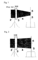
- Fig. 1 shows an example of the DOE homogenizer which converts a round Gaussian laser beam into a round uniform or quasi-uniform power density beam.
- a laser (not shown) emits a round Gaussian beam 2.
- the Gaussian power distribution is shown below on a left side.
- the Gaussian laser beam 2 goes into a DOE 3.
- the DOE 3 is a transparent plate having plenty of microelements (pixels) of different height (thickness) steps aligning lengthwise and crosswise.
- the DOE 3 has a function of diffracting light.
- the tophat power distribution of the diffracted beam 6 is shown below on a right side in Fig. 1.
- sections of the uniform-power diffracted beams 6 formed on the image plane 5 are circles.
- uniform power beams with elliptical sections can be also made on the image plane.
- a square sectioned (q ⁇ q) uniform (tophat) diffraction beam can be also made on the image plane by a DOE.
- a rectangle sectioned (q ⁇ w) uniform (tophat) diffraction beam can be also made on the image plane by another DOE.
- tophat means that the beam has uniform power distribution within a definite, restricted region but does not mean that the beam has a circular section.
- a wavelength of a laser beam is denoted by " ⁇ ".
- a DOE has many pixels with a plurality of steps of thickness.
- a total difference ⁇ D between the thickest part and the thinnest part of the DOE should coincide with a single wavelength ⁇ .
- the diameter of the round uniform density beam on the image plane is smaller than a diameter of an input laser beam.
- the diameter of the input laser beam is 2mm ⁇ and a diameter of an output uniform beam on the image is 1mm ⁇ .
- the beam diameter is reduced. Why such a shrinking optics is employed is that the power density of the laser beam is still weak. And required uniform power density for heat-processings should be far strong. The power density should be raised for compensating for imbalance by shrinking the beam diameter of the beam.
- the DOE produces the uniform power density (tophat) beam 6 on the image plane 5 by diffracting peripheral laser rays inward stronger and central laser rays inward weaker. Although the diffracted beam is uniform just on the image plane, the beam becomes non-uniform at other spots before or after the image plane.
- Fig. 1 is only a schematic view of the DOE.
- the DOE makes use of not refraction light but diffraction light.
- a variety of noise accompanies the DOE.
- the DOE utilizes only the first order diffraction light.
- Second order, third order or other higher order diffraction light or 0-th order light are yielded by the DOE.
- the higher order components and the 0-th order component are not simply converged as shown in Fig.1.
- the higher order and 0-th order components are noise.
- This is a weak point of DOEs.
- the noise is negligibly weak in ordinary cases of DOEs.
- Further drawback is the difficulty of processing caused by a variety of step heights of microelements (pixels). The degree of freedom is large for DOEs.
- DOEs are designed for making uniform power density only on an image plane, the uniformity of power density is rapidly degraded at spots deviating forward or backward from the image plane.
- the degree of freedom of design is high.
- the high degree of freedom prevents a designer from determining a single preferable DOE system for making a uniform power distribution beam.
- the DOE type homogenizers are plagued by many inherent disadvantages.
- the above-described lens type homogenizer (intensity-conversion lens & phase-compensation lens) can make a parallel, in-phase tophat beam. It is no matter for the lens type homogenizer whether the image plane deviates forward or backward from a determined position due to the parallelism and the in-phase property. Furthermore, the lens type homogenizer, which makes use of only refraction, is immune from problems of diffraction, e.g., higher order diffraction and 0-th order diffraction. The lens type homogenizer can produce a neat tophat beam on an image plane. The paired lens homogenizer is an excellent one.
- the lens homogenizer is quite suitable for producing a cylindrical, circular-sectioned uniform power beam.
- the lens homogenizer is incompetent to make a cylindrically-asymmetric, e.g., rectangular-, square- or ellipse-sectioned beam.
- Laser heat treatments do not always require rotationally-symmetric cylindrical uniform power beams.
- the desired sections of beams depend upon the kind of heat treatments and the shape of objects. Sometimes a square section qxq of a uniform power density beam is required. Sometimes a rectangle section q ⁇ w of a uniform power beam is required. Otherwise, a stripe section q ⁇ w (w ⁇ ⁇ q) may be required for a uniform power density beam.
- Lens homogenizers are incompetent for the purpose of preparing non-circle beams.
- DOEs diffraction optical elements
- a DOE is an optical device having plenty of tiny units (pixels) aligning crosswise and lengthwise in two dimensions, having different thicknesses (heights), and diffracting light into light with an arbitrary direction, shape and density distribution.
- a DOE has extremely high degree of freedom which is a product of the pixel number and the height step number. The high degree of freedom enables a DOE to make a q ⁇ q square sectioned uniform beam or a q ⁇ w rectangle sectioned uniform beam.
- DOE homogenizers are competent for such a purpose of making square, rectangular sectioned beams.
- a long stripe-sectioned (Q ⁇ w; Q> >w) uniform density beam as a limit of high Q/w rate rectangles is sometimes required.
- the liquid crystal display panel has plenty of thin film transistors made by evaporating amorphous silicon (a-Si) films on a glass substrate and processing the amorphous silicon films to transistor devices.
- a-Si amorphous silicon
- transistor devices For some purposes, amorphous silicon transistors are available. But, electron mobility on amorphous silicon is not high enough yet for producing liquid crystal display panels of high quality.
- the electron mobility can be enhanced by heating the amorphous silicon (a-Si), enlarging crystalline granules, and converting the amorphous silicon into polycrystalline silicon (poly-Si). But, it is undesirable to heat the amorphous silicon film on the glass substrate. If the amorphous silicon is heated by a heater, the glass substrate is also heated together. For example, it is preferable to heat the amorphous silicon at temperatures between 800°C and 1000°C for converting a-Si to poly-Si. Ordinary glass substrates have weak resistance against heat. If the glass substrate is heated up at 800°C, the glass substrate is softened and melted out. Direct heating is unsuitable.
- the laser light should have a short wavelength which amorphous silicon effectively absorbs. Infrared light and red-yellow visible light are not fully absorbed by amorphous silicon. Ultraviolet rays are desirable, since amorphous silicon can absorb the ultraviolet rays at high efficiency.
- Excimer lasers for example, KrF lasers or ArF lasers, can produce high power ultraviolet rays, which satisfy the condition imposed on wavelengths and power. But, the ultraviolet rays made by the KrF lasers or ArF lasers are still plagued by disorder of wavefronts and irregular, non-Gaussian power distribution. The KrF or ArF lasers are disqualified.
- a YAG laser emits a large power 1.06 ⁇ m Gaussian beam. But, 1.06 ⁇ m is infrared light which passes through amorphous silicon without loss. The YAG laser is incompetent. An SHG-YAG laser produces a 532 nm light beam. Amorphous silicon can absorb 532nm. Thus, SHG-YAG lasers are effective candidates for a light source of the high power heating treatment. The SHG-YAG lasers on sale are still annoyed with shortage of power. However, large power SHG-YAG lasers will be made in near future.
- the present invention relates to a DOE homogenizer for preparing a strong, uniform power density, zone-section beam for light heating treatment.
- Japanese Patent Publication No.2003-270585 "Laser illumination optical system, and exposure device, laser beam machining device and laser projection device using the same”, proposes an apparatus of employing laser diode array having a plurality of equivalent laser diodes aligning in series at a pitch p as a light source, placing the same number of holograms on extension of the laser diodes with the same pitch p, converting laser beams by the holograms into p ⁇ w rectangle uniform beams, lining up the rectangle beams on an image plane without margins without overlap. If two rectangle tophat beams were overlapped at edges, power density would be doubled at the spot. Interference would be induced by the overlapping. Thus overlapping was denied. If a gap were left between two rectangle beams, power density would be 0 at the gap. Thus a gap was denied.
- the prior art document tried to have produced a pN long uniform zone-sectioned beam by aligning N parallel lasers and N parallel holograms at a vertical pitch p, converting laser beams into p ⁇ w rectangle beams, and aligning the rectangle beams on an image plane without overlapping and gap.
- Equivalent lasers and equivalent holograms were available.
- a hologram is a device produced by irradiating a photosensitive medium with interfering object light and reference light from different angles, making interfering fringes in the medium, and recording the interfering fringes in the medium.
- the hologram is made by piling a photosensitive medium, e.g., photograph films on a side or sides of a substrate, irradiating the photosensitive medium with object light and reference light simultaneously.
- Japanese Patent Publication No.2003-270585 makes a recording element by making a diverging beam by a laser, dividing the diverging beam by a beam splitter, converting one divided beam into a parallel uniform power rectangle-sectioned beam by some means, irradiating a photosensitive medium on both sides by the diverging beam and the rectangle-sectioned beam, and developing the photomedium.
- a purpose of the present invention is to provide an apparatus for shaping Gaussian laser beams into a long stripe sectioned quasi-uniform power distribution beam.
- a stripe means a rectangle having a large horizontal/vertical ratio. It may be theoretically possible to make a quasi-uniform striped sectioned beam from a single Gaussian beam by a single DOE as shown in Fig.2.
- a DOE 3 has a function of enlarging an input beam 2 into a diverging, stripe-sectioned beam 4 which makes a stripe quasi-uniform (tophat) image 6 on an image plane 5.
- the section of the beam on the plane 5 is denoted by Q ⁇ w, wherein Q (length) is far larger than w (width) (Q > > w).
- the stripe-sectioned beam having a long Q as shown in Fig.2 would not be suitable for the above-mentioned purpose of heat-treatment of wide objects.
- Another candidate may be a device making use of a plurality of lasers which arrange plural lasers in parallel and holograms in parallel for converting the laser Gaussian beams into uniform power beams as proposed by the previously cited document of Japanese Patent Publication No.2003-270585.
- the prior art document proposed a hologram device for making a uniform power beam by producing a plurality of Gaussian beams by parallel-arranged lasers at a pitch p, converting the Gaussian beams into uniform beams of a section of a rectangle (p ⁇ q: p>q), where the length is equal to the laser pitch p, by holograms laid in front of the lasers, joining the rectangle beams without overlapping on a plane and obtaining a pN long stripe uniform beam.
- Use of a plurality of lasers enhances the total power of light.
- a laser diode array having tiny aligning laser diodes is a light source in Japanese Patent Publication No.2003-270585.
- Laser diode arrays are small.
- the pitch of lasers in the array is very short, e.g., a 400 ⁇ m to 500 ⁇ m pitch.
- a 5 laser array, a 10 laser array or a 20 laser array can be easily fabricated at low cost.
- Solid-state lasers and gas lasers have a large length, broad width, big height and heavy weight. It is impossible to align the solid-state lasers or gas lasers at a pitch of 500 ⁇ m like semiconductor laser diodes.
- the solid/gas lasers have wide discharging tubes. If a plurality of solid/gas lasers are aligned in parallel, the vertical pitch between the lasers will be 10mm, 20mm or more. Even if the lasers having extremely thin discharge tubes are used, the vertical pitch between the lasers is longer than 4mm.
- One purpose of the present invention is to provide an optical system for producing a long stripe-sectioned, uniform power density beam from such wide gas lasers or large solid-state lasers as light sources.
- the before-cited Japanese Patent Publication No.2003-270585 had a drawback of difficulty of adjusting joints between neighboring tophat beams without gap and overlapping.
- Another purpose of the present invention is to provide an optical system which has a wide tolerance for margins of the joints between the neighboring beams for facilitating to join the neighboring beams.
- a further purpose of the present invention is to provide an optical system which has a high degree of freedom of designing of positions, sizes and locations of lasers, DOEs and objects.
- Another purpose of the present invention is to provide an optical system immune from the 0-th order noise and higher order noise.
- This invention can be applied to both a shrinking optical system and an enlarging optical system.
- An (shrinking) optical system of the present invention prepares a long stripe-sectioned, quasi-uniform power density beam by aligning a plurality of parallel lasers for producing Gaussian beams of a diameter d, aligning the same number of off-axis type DOEs in an order of increasing diffraction angles ⁇ outward, diffracting the d- ⁇ Gaussian laser beams by the DOEs into quasi-uniform power rectangle (q ⁇ w; w ⁇ q ⁇ d) sectioned beams at an image plane, superposing the quasi-uniform stripe sectioned beams partially overlapped at edges, and forming a long quasi-uniform striped sectioned beam on the image plane.
- An essential part of the system is off-axis DOEs.
- a system can be built only by off-axis DOEs. But another system can include an on-axis type DOE.
- a mixture system should dispose an on-axis DOE at the center, position off-axis DOEs at off-axis spots on both sides in the order of increasing diffraction angles ⁇ outward for guiding diffraction beams to converge toward a center on the image plane. Neighboring reduced rectangle-sectioned diffraction patterns are partially superposed at peripheries on the image plane for making a unified continual uniform power density stripe beam on the plane.
- the above optical system aims at shrinking the incidence beam in size for producing a diffracted beam having stronger uniform power density.
- this invention can also make another optical system aiming at enlarging the incidence beam in size for producing a diffracted beam having weaker uniform power density.
- the present invention can give an enlarging optical system as follows.
- An (enlarging) optical system of the present invention prepares a long stripe-sectioned, quasi-uniform power density beam by aligning a plurality of parallel lasers for producing d- ⁇ Gaussian beams, aligning the same number of off-axis type DOEs in an order of increasing diffraction angles ⁇ outward, diffracting the d- ⁇ Gaussian laser beams by the DOEs into quasi-uniform power rectangle (q ⁇ w; w ⁇ q, d ⁇ q) sectioned beams at an image plane, superposing the quasi-uniform stripe sectioned beams partially overlapped at edges, and forming a long quasi-uniform striped sectioned beam on the image plane.
- the fact that the DOEs are an off-axis type is important in the present invention.
- the off-axis DOEs can eliminate 0-th order noise which passes straight through a DOE. This is a great advantage of off-axis DOEs. Unlike a lens, the 0-th order noise accompanies on-axis type DOEs.
- the present invention can remove the 0-th order noise by the use of off-axis DOEs.
- off-axis DOEs can eliminate minus order (-1st, -2nd, -3rd ... orders) diffraction beams.
- off-axis DOEs can also remove plus higher order (+2nd, +3rd, +4th 7) diffraction, since the plus higher order beams are diverted from the object.
- the off-axis optics has an advantage of eliminating 0-th order, plus higher order and minus order diffraction beams from the image plane.
- the sum of the neighboring diffracted beams is constant in the vicinity of joints by partially superposing mild sloping functions. Since two neighboring beams should be superposed with continuity, the two should not be tophats. Mild steep hills are suitable for superposition.
- a supergaussian is a function taking a form of exp(-2(2x/q') m ).
- m is a positive integer which is called a supergaussian order parameter.
- supergaussians become a tophat function (rectangle function or step function) which takes 1 in the region -q'/2 ⁇ x ⁇ q'/2 and 0 in the regions x ⁇ -q'/2 and q'/2 ⁇ x.
- the supergaussian can represent a beam having a rectangle section of a length q'.
- q'/2 means a half of the length.
- Neighboring beams are overlapped at joints by superposing partially the neighboring tails for making a smooth flat plateau.
- Individual diffraction beams should take not a tophat shape but a mild sloped hill shape.
- the off-axis value (offset) g is an x-coordinate of the center of a diffracted beam on the image plane.
- an asymmetric system can be built with only off-axis DOEs.
- q' is the length of the diffracted stripe-sectioned beam and q is the pitch of the superposition of the diffracted beams.
- the relation between q' and q is described.
- the beam length q' is nearly equal to the beam pitch q. But strictly speaking, the beam length q' and the pitch q are not exactly equal for the supergaussian functions.
- the above x-relating function takes about 1 for -q/2 ⁇ (x-g) ⁇ q/2 and takes 0 for (x-g) ⁇ -q/2 or q/2 ⁇ (x-g).
- the above y-relating function takes about 1 for -w/2 ⁇ y ⁇ w/2 and takes 0 for y ⁇ -w/2 or w/2 ⁇ y.
- a whole beam distribution function relying upon Fermi's function is obtained by combining the above x-direction function and the y-direction function.
- a series of Fermi's functions enables the superposition to give a value 1 at interfaces as a sum of neighboring beams.
- the values of g have been already described for the odd number or even number of DOEs for supergaussian distribution functions.
- a set of off-axis DOEs can build a desired optical system, even if the number of lasers and DOEs is odd. In any means, what is significant is off-axis DOEs.
- a formula for calculating intensity distribution of light diffracted on an image plane by a DOE has been well known.
- the beam line is taken to be parallel to a z-axis.
- a plane vertical to the beam line has (x, y) coordinates.
- Amplitude/phase distribution of an incidence beam is denoted by a(x, y, 0).
- Changes of a phase and an amplitude induced by passing the DOE are denoted by "t(x, y)".
- the integral dxdy should be done on the plane of the DOE.
- the DOE is divided into plenty of pixels which have a value for t(x, y).
- the integral on the DOE should be replaced by summation of the functions with regard to pixels.
- the incident beam is Gaussian.
- Extra heights of pixels from a standard height are denoted by ⁇ h(x, y).
- W(x', y') in the above equation is a quasi-uniform power distribution wave function on the image (x', y', f).
- W(x', y') is calculated by giving the phase ⁇ (x, y) to each pixel and summing the product following the double integral for all pixels. If the calculated W(x', y') coincides with the above-mentioned quasi-uniform distribution function, for example, a supergaussian or Fermi's function, the t(x, y) is a desirable solution giving probable pixel phases ⁇ (x, y) or heights ⁇ h(x, y) of the DOE. If W(x', y') deviates from the predetermined quasi-uniform distribution function, the phase function ⁇ (x, y) should be amended for reducing the difference.
- the phase function ⁇ (x, y) should be amended for reducing the difference.
- the present invention proposes an off-axis optical system which produces a stripe-sectioned uniform power density beam from a plurality of beams emitted from lasers by aligning the lasers side by side in an x-direction at a pitch p, aligning off-axis type DOEs, which diffract laser Gaussian beams into off-axis rectangle sectioned uniform beams at definite diffraction angles, on extensions of the lasers side by side in an order of higher diffraction angles on outer sides, making a plurality of rectangle-sectioned uniform power beams, superposing the rectangle-sectioned uniform power beams with smooth continuity at fringes, and forming a long stripe sectioned uniform beam on an image plane.
- Off-axis DOEs are dominant, main, indispensable optical parts in the present invention.
- the whole of the optical system can be constructed only with the off-axis type DOEs.
- Symmetric even-number DOE systems can be built without on-axis DOEs.
- Asymmetric odd-number DOE systems can be built without on-axis DOEs.
- An on-axis DOE can be included in the optical system of the invention in the case of symmetric odd-number DOEs.
- the diffracted beam should not have perfect uniform power density (tophat) but should have quasi-uniform density having a flat middle plateau and continually falling sides. The continually falling sides are necessary for superposing neighboring quasi-uniform beams without discontinuity at boundaries (fringes).
- high order number parameter m is not desirable for supergaussian functions for the beam density.
- Two neighboring beams are partially superposed at joints.
- the beam power density is a sum of the neighboring beams at the joints since two beams are superposed. There is no anxiety of interference at the joints, because the light sources are independent and incoherent.
- the number of lasers is denoted by "N".
- the lasers are aligned in series at a pitch p.
- the width of laser arrangement in an x-direction is Np.
- the total width of continually superposed beams is Nq on the image plane.
- the total width of the superposed diffracted beam is shorter than the total width of the arrange lasers (Nq ⁇ Np).
- the laser beam power is concentrated into higher power light on the image plane suitable for heat treatment.
- the superposed unified beam has quasi uniform density in the stripe (long rectangle) section.
- Objects can be heat-treated, for example, welding, annealing, cutting by irradiating objects with the stripe-sectioned uniform density beam.
- the beam is an assembly of diverging (or converging) slanting rays. Diffracted beams are partially superposed at joints. The density of power is continual and uniform also near the joints. The superposed beam is a nearly uniform stripe beam with side moderate slopes on the objects.
- the off-axis DOE plays a role of making a rectangular-sectioned, quasi-uniform density beam at an off-axis spot on the image plane by diffracting the laser beam with a definite oblique angle. Since the beam is diffracted at a slanting direction, the DOE is a new, strange optical element endowed with new functions and advantages. An ordinary on-axis type DOE is annoyed with the 0-th order noise, which progresses along a straight line without being diffracted. But the off-axis DOE proposed by the present invention is fully immune from the 0-th order noise, because the DOE diffracts an input laser beam at a slanting direction. The off-axis DOE can suppress plus sign higher order diffraction rays.
- the higher order (+2nd, +3rd, +4th,...) diffraction rays which have larger oblique angles, are diverted from objects.
- the off-axis DOE can exclude fully unnecessary light components, for example, the 0-th order noise and plus higher order diffraction rays.
- the effect of elimination of the 0-th order noise is, in particular, a big advantage of the present invention.
- off-axis DOEs facilitates the production of shrinking optical systems or enlarging optical systems.
- the off-axis DOEs have far higher degree of freedom than on-axis DOEs.
- the off-axis DOEs are superior to the on-axis DOEs in the degree of freedom, suppression of noise and concentration of laser power.
- Fig. 3 shows an example of a superposing DOE homogenizer of the present invention making use of three DOEs in a beam shrinking case.
- Fig.4(a) denotes the power distribution of three diffracted beams on an image plane (I).
- Fig.4(b) denotes the power distribution of a unified, superposed beam on the image plane (I).
- the example assembles a first DOE, a second DOE and a third DOE aligning in series in a base line vertical to beam lines.
- the number of sets of DOEs and lasers is three in the example. But the number of DOE/laser sets can be chosen to be an arbitrary integer, i.e., 2, 4, 5, 6....
- the whole DOE system can be built with off-axis DOEs without an on-axis DOE.
- the DOE/laser number m is an odd integer, one on-axis DOE is required for making a symmetric system. But if the symmetry is not required, a homogenizer system can be composed only by off-axis DOEs for both even integer m and odd integer m.
- the beam propagating direction is denoted by a z-axis.
- Each laser is parallel to the z-direction.
- DOEs and lasers are arranged in series side by side in parallel to the x-direction.
- DOEs and an image plane are parallel to a xy-plane. The output stripe-sectioned beam diffracted by the DOEs on the image plane expands in the x-direction.
- a middle DOE (1) is an on-axis type.
- Side DOE (2) and DOE (3) are an off-axis type.
- Three equivalent lasers (not shown) are positioned in front of the DOEs. The three lasers emit parallel Gaussian beams. The laser Gaussian beams go in parallel into the DOEs (2), (1) and (3).
- the distance (laser pitch) between neighboring laser centers is equal to the distance (DOE pitch p) between neighboring DOE centers.
- the example is a shrinking optical system for reducing the width of beams.
- the pitch q (image pitch) of diffracted beams on the image (I) is smaller than the DOE pitch p (q ⁇ p).
- a total width of the diffracted unified beam on the image is 3q.
- a total width of the aligning DOEs is 3p. Here,3p>3q.
- the middle on-axis DOE (1) diffracts and shrinks a cylindrical Gaussian laser beam of a diameter d along the beam line (z-direction) into a smaller q ⁇ w (q > > w) rectangle quasi-uniform beam as shown in Fig.5.
- the upper off-axis DOE (2) diffracts and shrinks a cylindrical Gaussian laser beam of a diameter d along a downward inclination line (on zx-plane) into a smaller q ⁇ w (q> >w) rectangle quasi-uniform beam at an off-axis spot as shown in Fig.6.
- the lower off-axis DOE (3) diffracts and shrinks a cylindrical Gaussian laser beam of a diameter d along an upward inclination line (on zx-plane) into a smaller q ⁇ w (q > > w) rectangle quasi-uniform beam at an inverse off-axis spot as shown in Fig.7.
- Fig.3 which assembles off-axis and on-axis DOEs, produces three quasi-uniform, stripe-shaped diffracted beams, superposes the three beams partially at fringes (Fig.4(a)) and makes a unified quasi-uniform long 3q ⁇ w (3q> >w) stripe sectioned beam (Fig.4(b)) on the image.
- Interference at the joining regions induces no problem. No interference allows us to partially superpose neighboring laser beams on the image plane at the butting regions. Use of isolated, separated individual lasers denies interference. Interference occurs only between beams which have originally been emitted from the same laser.
- off-axis DOEs Use of off-axis DOEs is the gist of the present invention.
- the off-axis DOEs can eliminate the 0-th order light component and positive higher order light components. Elimination of the 0-th order and higher order components enables the off-axis DOEs to realize low noise diffraction beams on image planes.
- Fig.17 shows an off-axis optical system (Fig. 17(a)) and an on-axis optical system (Fig. 17(b)) for size shrinking cases.
- the on-axis optical system requires that the laser pitch p should be equal to a DOE arranging pitch.
- short light zones (mq) require reduction of the pitch p and the size of the DOEs and the size of the lasers.
- mq short light zones
- the present invention relying on off-axis DOEs has high degree of freedom.
- the pitch of aligning lasers is not determined thereby. Even when the pitch of aligning lasers is predetermined, the size of the rectangle diffracted beam on an image is not determined.
- the size of the diffracted beams and the laser aligning pitch are independent parameters.
- the high degree of freedom derives from the adoption of off-axis type DOEs of the present invention.
- the high degree of freedom is one of advantages of the present invention.
- This invention can satisfy another requirement of preparing a diffraction beam having a short stripe (short Nq) section with high power.
- high power lasers should be arranged in parallel along a line.
- High power lasers have a large width, which widens the pitch p of an array of lasers. The wide pitch would weaken light power on the image plane in the case of on-axis DOEs.
- f is a focal length of the DOE
- ⁇ is a wavelength of the incidence laser light
- D is a beam diameter of the incidence laser beam.
- the off-axis type shrinking optical system can make use of a large diameter D of the incidence laser beam.
- the shrinking optical system can reduce the value of the diffraction limit by raising D.
- the diffraction limit determines the minimum resolution.
- the resolution is improved by the shrinking off-axis optical system. High resolution is one of the advantages of the shrinking type optical system built by the present invention.
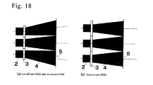
- Fig.18 compares an enlarging off-axis optical system (Fig. 18(a): the present invention) with an enlarging on-axis optical system (Fig. 18(b): imaginary example not prior art).
- the present invention has high degree of freedom.
- superposed beams extend along an x-axis on an image plane 5. Even when the size of a rectangular uniform beam on an image is predetermined, the laser aligning pitch p is not determined. Even when the laser pitch p is predetermined, the size of the rectangular uniform beam is not determined by the laser pitch p. Both the laser pitch p and the image size are independent parameters which can be arbitrarily designed.
- the virtual on-axis (not prior art) optical system of Fig. 18(b) aligns a plurality of lasers at the same pitch as the pitch of the diffracted beams aligning in the x-direction on the image.
- the laser axes should always coincide with the centers of the diffracted beams.
- a bulky apparatus is undesirable since the apparatus would occupy an extra wide space in factories.
- the imaginary on-axis optical system would be inferior to the off-axis one designed by teaching of the present invention.
- the off-axis type of Fig. 18 (a) of the present invention enables lasers to align at a reduced pitch p and DOEs to be miniaturized.
- the reduction of pitch can cut the size of the whole apparatus.
- the off-axis optical system has an advantage of reducing the area occupied by the apparatus.
- Fig.8 shows a disposition of three DOEs and an image plane superposing three images made by the DOEs.
- a homogenizer is an optical system aligning three DOEs in contact on a plane vertical to a beam line.
- a first homogenizer is an off-axis type DOE.
- a second homogenizer is an on-axis type DOE.
- a third homogenizer is an off-axis type DOE.
- a distance between the center of the first homogenizer DOE and the center of the second homogenizer DOE is 4mm.
- a distance between the center of the second DOE and the center of the third DOE is 4mm.
- a distance between a DOE plane and the image plane is 100mm.
- a light source is an SHG-YAG laser.
- the wavelength of the beam emitted from the laser is 532nm.
- the diameter of the beam is 2mm ⁇ .
- the edge of a Gaussian beam is defined at a point at which the power density falls to e -2 times as small as the maximum power.
- the zero emission angle means that the beam is a perfect parallel beam.
- the power distribution of the laser is Gaussian.
- a DOE shown in Fig. 10 is built by pixels which are minimum, fundamental elements.
- a DOE is an assembly of pixels.
- a pixel is a square of 5 ⁇ m ⁇ 5 ⁇ m.
- a definite height (or thickness) is allotted to a pixel in a DOE.
- the DOE has 800 pixels ⁇ 800 pixels.
- An effective region of the DOE which the pixels occupy is 4000 ⁇ m ⁇ 4000 ⁇ m.
- the DOE is made of fused silica.
- the focal length f can be defined for the DOE, since the DOE has a function of convergence like a convex lens.
- the phase step number means the number of steps which can be allocated to pixels.
- the phase step number is 16.
- the pixels can take 16 different steps.
- Fig.9 signifies the 16 steps of pixels.
- the phase step number is order of the power of 2.
- the 16 step number is not so large. 256 steps, 128 steps, 64 steps or 32 steps can be chosen as the number of phase steps of DOEs. The more the step number rises, the higher the resolution of diffracted images increases.
- the purpose of the present invention is not to build complicated diffraction patterns but to make simple uniform power distribution patterns on an image plane. Such a small number of steps is chosen for the steps of the DOEs. Off course 8 steps are also available.
- the phase number is s and the unit step height is ⁇ , the product s ⁇ should coincide with a single wavelength difference.
- s ⁇ (n-1) ⁇ .
- the edge of a beam is defined as a spot where the power density falls to 1/e 2 of the central power density.
- An explicit expression of the diffracted beam density on the image is given by exp ⁇ -2(2(x+q)/3) 3.4 ⁇ exp ⁇ -2(2y/0.1) 2 ⁇ .
- the half size of the x-direction is 3/2.
- the number 2 is included as a head multiplier 2 of 2(x+q).
- the half size of the y-direction is 0.1/2.
- the number 2 is included as a head multiplier 2 of 2y.
- the discrepancy derives from the definition of the edges of beams not at the spot of a fall to 0.5 but at the spot of a fall to e -2 of the maximum power due to the supergaussian function.
- the diffraction efficiency is 90.53%, which seems to be a slightly low value.
- the reduction of about 10% is caused by off-axis type slanting diffraction instead of vertical diffraction.
- Fig. 10 is a diagram showing height (phase) distribution of pixels of the first DOE by monotone variation from black to white.
- a change from white to black corresponds to the full 16 steps of variation of thickness (heights or phase).
- Curvatures of the concentric arcs decrease from left to right. Like a Fresnel lens, the concentric arcs have a function of bending and converging a beam to the right. The macroscopic concentric arcs make an image at an off-axis spot on the image.
- the leftward arcs have steep slanting curves near ends.
- the slanting angles are about 20 degrees to 40 degrees.
- a pixel is a square of 5 ⁇ m ⁇ 5 ⁇ m.
- a definite height (or thickness) is allotted to a pixel in a DOE.
- An effective region of the DOE which the pixels occupy is 4000 ⁇ m ⁇ 4000 ⁇ m.
- the DOE is made of fused silica.
- the diffracted beam size is 3mm ⁇ 0.1mm.
- the second DOE is an on-axis type.
- the supergaussian function of the striped uniform beam diffracted by the second DOE is represented by exp ⁇ -2(2x/3) 3.4 ⁇ exp ⁇ -2(2y/0.1 ) 2 ⁇ .
- the diffraction efficiency is 96.54%.
- the high efficiency drives from the on-axis property.
- Fig. 11 is a diagram showing height (phase) distribution of pixels of the second DOE by monotone variation from black to white.
- An explicit expression of the diffracted beam density is given by exp ⁇ -2(2(x-q)/3) 3.4 ⁇ exp ⁇ -2(2y/0.1) 2 ⁇ .
- the diffraction efficiency is 90.52%, which seems to be a slightly low value.
- the reduction of about 10% is caused by off-axis, slanting diffraction instead of vertical diffraction.
- Fig.12 is a diagram showing heights (phases) distribution of pixels of the third DOE by monotone variation from black to white.
- the curvature of the concentric arcs decreases from right to left.
- the concentric arcs have a function of bending and converging a beam to the left.
- the macroscopic concentric arcs make an image at an off-axis spot on the image.
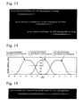
- Fig.13 shows beam intensity distributions produced by the first DOE, second DOE and third DOE by white slots appearing on a black background.
- the white slots seem like needles with sharpened edges.
- the white needle denotes not the spatial distribution but the power distribution.
- the beam section is a regular rectangle of 3mm ⁇ 0.1mm.
- Fig. 14 is a graph showing the same beam intensity distributions prepared by the DOEs.
- An abscissa is the x-coordinate (mm).
- An ordinate is the power density, which takes 1 at the maximums of diffracted beams.
- the diffracted beams are not rigorously uniform step functions (tophat) but round hills with mild slopes. The hills resemble Gaussian.
- Fig.15 shows an intensity distribution of the unified, superposed beam on the image plane by a long white slot appearing on a black background.
- the white slot like a sharp needle denotes not the spatial distribution but the power distribution.
- the white slot denotes mild uniformity of power density in the longitudinal direction (x-direction).
- Fig.16 is a graph showing the same intensity distribution of the superposed beam.
- An abscissa is the x coordinate.
- An ordinate is superposed power density.
- the power is nearly constant in a 6.4mm long zone between - 3.2mm and +3.2mm.
- Both sides have blunt slopes deriving from low order parameter supergaussians.
- the appearance of sloping sides is unavoidable
- the power distribution has a wide flat plateau of a 6.4mm length. Uniform power irradiation can be realized by placing an object within the plateau and scanning the object in the y-direction.
Landscapes
- Physics & Mathematics (AREA)
- General Physics & Mathematics (AREA)
- Optics & Photonics (AREA)
- Diffracting Gratings Or Hologram Optical Elements (AREA)
- Laser Beam Processing (AREA)
Abstract
Description

Claims (5)
- A superposing diffraction optical element (DOE) homogenizer optical system comprising:a plurality of parallel lasers emitting Gaussian beams of a diameter d along beam lines extending in a z-direction and aligning at a pitch p in an x-direction; andoff-axis DOEs diffracting the Gaussian laser beams at inclining diffraction angles, making quasi-uniform density q×w (q>w) stripe-sectioned beams of a length q smaller than p (p>q) on an image plane I (xy-plane) which is distanced by a focal length f from the DOEs and aligning at the pitch p on an x-direction extending base line K vertical to the beam lines in an order of larger inclining diffraction angles outward and smaller inclining diffraction angles inward on extensions of the beam lines of the lasers,the DOEs diffracting and shrinking the laser Gaussian beams into the quasi-uniform density stripe-sectioned beams, superposing the diffracted beams partially at edges and making a unified x-direction extending quasi-uniform beam on the image plane I.
- A superposing diffraction optical element (DOE) homogenizer optical system comprising:a plurality of parallel lasers emitting Gaussian beams of a diameter d along beam lines extending in a z-direction and aligning at a pitch p in an x-direction; andoff-axis DOEs diffracting the Gaussian laser beams at inclining diffraction angles, making quasi-uniform density q×w (q>w) stripe-sectioned beams of a length q larger than p (p < q) on an image plane I (xy-plane) which is distanced by a focal length f from the DOEs and aligning at the pitch p on an x-direction extending base line K vertical to the beam lines in an order of larger inclining diffraction angles outward and smaller inclining diffraction angles inward on extensions of the beam lines of the lasers,the DOEs diffracting and enlarging the laser Gaussian beams into the quasi-uniform density stripe-sectioned beams, superposing the diffracted beams partially at edges and making a unified x-direction extending quasi-uniform beam on the image plane I.
- The superposing diffraction optical element (DOE) homogenizer optical system according to claim 1 or 2, further comprising an extra middle laser emitting a Gaussian beam of a diameter d along a beam line extending in the z-direction and an extra on-axis DOE diffracting a Gaussian laser beam of the middle laser along the beam line, making a quasi-uniform density q×w (q>w) stripe-sectioned beam on the image plane I and lying on an extension of the beam line of the extra laser and the off-axis DOEs alining on both sides or one side of the on-axis DOE in an order of larger inclining diffraction angles outward and smaller inclining diffraction angles inward on extensions of the beam lines of the lasers.
- The superposing diffraction optical element (DOE) homogenizer optical system according to any claim from claim 1 to claim 3, wherein power density of the quasi-uniform power density stripe-sectioned beam on the image plane I (xy-plane) by the DOE is represented by a supergaussian function exp(-2(2(x-g)/q')m-2(2y/w)n), where q' is a length, w is a depth, supergaussian coefficients are m=3 to 20 and n=2 to 10, and g is an off-axis value.
- The superposing diffraction optical element (DOE) homogenizer optical system according to any claim from claim 1 to claim 3, wherein power density of the quasi-uniform power density stripe-sectioned beam on the image plane I (xy-plane) by the DOE is represented by a Fermi function [exp[-β{x-g+(q/2)}]+1]-1[exp[β{x-g-(q/2)}]+1]-1[exp[-γ{y+(w/2)}]+1]-1[exp[γ{y-(w/2)}]+1]-1, where q is a length, w is a depth, β is β=20/q to 5/q, γ is γ=20/w to 5/w and g is an off-axis value.
Applications Claiming Priority (2)
| Application Number | Priority Date | Filing Date | Title |
|---|---|---|---|
| JP2004066616A JP4033151B2 (en) | 2004-03-10 | 2004-03-10 | Superposition type DOE homogenizer optical system |
| JP2004066616 | 2004-03-10 |
Publications (3)
| Publication Number | Publication Date |
|---|---|
| EP1574892A2 true EP1574892A2 (en) | 2005-09-14 |
| EP1574892A3 EP1574892A3 (en) | 2006-08-16 |
| EP1574892B1 EP1574892B1 (en) | 2008-04-16 |
Family
ID=34824566
Family Applications (1)
| Application Number | Title | Priority Date | Filing Date |
|---|---|---|---|
| EP04024311A Expired - Lifetime EP1574892B1 (en) | 2004-03-10 | 2004-10-12 | Superposing diffraction optical element homogenizer optical system |
Country Status (5)
| Country | Link |
|---|---|
| US (1) | US6967777B2 (en) |
| EP (1) | EP1574892B1 (en) |
| JP (1) | JP4033151B2 (en) |
| KR (1) | KR101029926B1 (en) |
| DE (1) | DE602004013119T2 (en) |
Cited By (4)
| Publication number | Priority date | Publication date | Assignee | Title |
|---|---|---|---|---|
| WO2010130415A1 (en) * | 2009-05-14 | 2010-11-18 | Limo Patentverwaltung Gmbh & Co. Kg | Arrangement for producing laser radiation, and laser device comprising such an arrangement |
| CN103487943A (en) * | 2013-10-10 | 2014-01-01 | 中国科学院上海微系统与信息技术研究所 | Laser point light source cluster generating device |
| CN111381426A (en) * | 2018-12-29 | 2020-07-07 | 深圳光峰科技股份有限公司 | Light source system and projection equipment |
| CN113325596A (en) * | 2021-06-04 | 2021-08-31 | 江西欧迈斯微电子有限公司 | Diffractive optical element and optical equipment |
Families Citing this family (19)
| Publication number | Priority date | Publication date | Assignee | Title |
|---|---|---|---|---|
| US7820936B2 (en) * | 2004-07-02 | 2010-10-26 | Boston Scientific Scimed, Inc. | Method and apparatus for controlling and adjusting the intensity profile of a laser beam employed in a laser welder for welding polymeric and metallic components |
| JP4887759B2 (en) * | 2005-11-30 | 2012-02-29 | セイコーエプソン株式会社 | LIGHTING DEVICE, LIGHTING DEVICE CONTROL METHOD, AND PROJECTOR |
| US8002756B2 (en) * | 2006-12-08 | 2011-08-23 | Becton, Dickinson And Company | Method and apparatus for delivering a therapeutic substance through an injection port |
| US8029637B2 (en) * | 2007-11-29 | 2011-10-04 | Hitachi Global Technologies Netherlands, B.V. | System, method and apparatus for ultraviolet curing of adhesives with light beam shaping in disk drive manufacturing |
| TW200925764A (en) * | 2007-12-06 | 2009-06-16 | Young Optics Inc | Display method and illumination system thereof |
| DE102008000116A1 (en) * | 2008-01-21 | 2009-07-30 | Seereal Technologies S.A. | Illumination unit for a holographic reconstruction system |
| DE102008027229B4 (en) * | 2008-06-06 | 2016-06-30 | Limo Patentverwaltung Gmbh & Co. Kg | Apparatus for beam shaping |
| JP5987375B2 (en) * | 2012-03-13 | 2016-09-07 | セイコーエプソン株式会社 | Optical pattern forming device, electronic equipment and laser processing machine |
| JP6119761B2 (en) * | 2012-10-16 | 2017-04-26 | 住友電気工業株式会社 | Optical path control device |
| DE102013101147A1 (en) | 2013-02-05 | 2014-08-21 | Limo Patentverwaltung Gmbh & Co. Kg | Device for transforming and dividing laser beam into sub-beams, has partial transparent substrate whose functional surface is designed such that beam is divided into sub-beams and transformed so as to have top-hat-profile |
| JP6070274B2 (en) * | 2013-02-28 | 2017-02-01 | 旭硝子株式会社 | Diffusion element, illumination optical system and measuring device |
| JP6249225B2 (en) * | 2014-03-13 | 2017-12-20 | パナソニックIpマネジメント株式会社 | Laser processing apparatus and laser processing method |
| DE102014205294A1 (en) * | 2014-03-21 | 2015-09-24 | Automotive Lighting Reutlingen Gmbh | lighting device |
| WO2016185853A1 (en) * | 2015-05-15 | 2016-11-24 | ソニー株式会社 | Light source device, illuminating device, and projector |
| US9733485B2 (en) | 2015-10-30 | 2017-08-15 | Himax Technologies Limited | Collimating lens |
| US10545289B1 (en) * | 2018-08-08 | 2020-01-28 | Lockheed Martin Corporation | Planar optical head for free space optical communications, coherent LIDAR, and other applications |
| CN111550749A (en) * | 2019-01-23 | 2020-08-18 | 奇景光电股份有限公司 | Lighting device |
| EP3933490B1 (en) | 2019-03-13 | 2024-06-12 | Lg Chem, Ltd. | Diffractive light guide plate |
| KR102914553B1 (en) * | 2019-08-02 | 2026-01-20 | 삼성디스플레이 주식회사 | Diffuser_based optical system for laser beam homogenization and laser annealing device including the same |
Family Cites Families (7)
| Publication number | Priority date | Publication date | Assignee | Title |
|---|---|---|---|---|
| US6102552A (en) | 1996-10-18 | 2000-08-15 | Hewlett-Packard Company | Laser-array based digital illuminator |
| RU2137978C1 (en) * | 1998-03-26 | 1999-09-20 | Открытое акционерное общество "ЛОМО" | Lighting fixture with asymmetric distribution of light flux relative to optical axis |
| JP2001174615A (en) | 1999-04-15 | 2001-06-29 | Nikon Corp | Diffractive optical element, method for manufacturing the element, illumination device including the element, projection exposure apparatus, exposure method, light homogenizer, method for manufacturing light homogenizer |
| US6462891B1 (en) * | 2000-04-20 | 2002-10-08 | Raytheon Company | Shaping optic for diode light sheets |
| US6731432B1 (en) * | 2000-06-16 | 2004-05-04 | Mem Optical, Inc. | Off-axis diffractive beam shapers and splitters for reducing sensitivity to manufacturing tolerances |
| JP2003149594A (en) * | 2001-11-16 | 2003-05-21 | Ricoh Co Ltd | Laser illumination optical system and exposure apparatus, laser processing apparatus, and projection apparatus using the same |
| JP2003270585A (en) * | 2002-03-18 | 2003-09-25 | Ricoh Co Ltd | Laser illumination optical system and exposure apparatus, laser processing apparatus, and projection apparatus using the same |
-
2004
- 2004-03-10 JP JP2004066616A patent/JP4033151B2/en not_active Expired - Fee Related
- 2004-10-05 KR KR1020040079095A patent/KR101029926B1/en not_active Expired - Fee Related
- 2004-10-12 DE DE602004013119T patent/DE602004013119T2/en not_active Expired - Lifetime
- 2004-10-12 EP EP04024311A patent/EP1574892B1/en not_active Expired - Lifetime
- 2004-12-03 US US11/002,883 patent/US6967777B2/en not_active Expired - Lifetime
Cited By (9)
| Publication number | Priority date | Publication date | Assignee | Title |
|---|---|---|---|---|
| WO2010130415A1 (en) * | 2009-05-14 | 2010-11-18 | Limo Patentverwaltung Gmbh & Co. Kg | Arrangement for producing laser radiation, and laser device comprising such an arrangement |
| CN102395914A (en) * | 2009-05-14 | 2012-03-28 | Limo专利管理有限及两合公司 | Arrangement for producing laser radiation, and laser device comprising such an arrangement |
| US8749888B2 (en) | 2009-05-14 | 2014-06-10 | Limo Patentverwaltung Gmbh & Co. Kg | Arrangement for producing laser radiation, and laser device comprising such an arrangement |
| CN102395914B (en) * | 2009-05-14 | 2014-06-11 | Limo专利管理有限及两合公司 | Arrangement for producing laser radiation, and laser device comprising such an arrangement |
| CN103487943A (en) * | 2013-10-10 | 2014-01-01 | 中国科学院上海微系统与信息技术研究所 | Laser point light source cluster generating device |
| CN103487943B (en) * | 2013-10-10 | 2016-04-13 | 中国科学院上海微系统与信息技术研究所 | A kind of generation device of laser point light source cluster |
| CN111381426A (en) * | 2018-12-29 | 2020-07-07 | 深圳光峰科技股份有限公司 | Light source system and projection equipment |
| CN113325596A (en) * | 2021-06-04 | 2021-08-31 | 江西欧迈斯微电子有限公司 | Diffractive optical element and optical equipment |
| CN113325596B (en) * | 2021-06-04 | 2023-04-04 | 江西欧迈斯微电子有限公司 | Diffractive optical element and optical equipment |
Also Published As
| Publication number | Publication date |
|---|---|
| KR101029926B1 (en) | 2011-04-18 |
| US20050200958A1 (en) | 2005-09-15 |
| EP1574892A3 (en) | 2006-08-16 |
| DE602004013119T2 (en) | 2009-05-20 |
| EP1574892B1 (en) | 2008-04-16 |
| DE602004013119D1 (en) | 2008-05-29 |
| JP2005257830A (en) | 2005-09-22 |
| JP4033151B2 (en) | 2008-01-16 |
| KR20050091890A (en) | 2005-09-15 |
| US6967777B2 (en) | 2005-11-22 |
Similar Documents
| Publication | Publication Date | Title |
|---|---|---|
| EP1574892B1 (en) | Superposing diffraction optical element homogenizer optical system | |
| US6909546B2 (en) | Multipoint lump homogenizing optical system | |
| US5861991A (en) | Laser beam conditioner using partially reflective mirrors | |
| KR102363017B1 (en) | A method for projection comprising a projection device and optical free-form surfaces | |
| TW458835B (en) | Laser machining apparatus | |
| CN115121940B (en) | Laser beam irradiation | |
| TW528879B (en) | Illumination optical system and laser processor having the same | |
| US20090016400A1 (en) | Multi-beam laser apparatus | |
| KR20140104973A (en) | Multiple beam combiner for laser processing apparatus | |
| US9547176B2 (en) | Device for generating laser radiation having a linear intensity distribution | |
| JP2007310368A (en) | Propagating method of shaped beam using homogenizer and laser processing optical system using the same | |
| US20120153189A1 (en) | Optical system for generating a light beam for treating a substrate | |
| US11878368B2 (en) | Laser machining system | |
| KR100541126B1 (en) | Laser beam uniform irradiation optical system | |
| JP3955587B2 (en) | Laser irradiation device | |
| Zheng et al. | Partially coherent laser beam shaping in a zoom homogenizer | |
| JP3563065B2 (en) | Laser beam uniform irradiation optical system | |
| CN115963646A (en) | Shaping projection system and method for light beams of light source | |
| US20240036338A1 (en) | Systems, devices, and methods for laser beam generation | |
| JP3537424B2 (en) | Laser beam uniform irradiation optical system | |
| CN222319215U (en) | Optical system | |
| TWI823308B (en) | Laser processing system | |
| JP2008053317A (en) | Irradiation optical system | |
| JP2004272281A (en) | Laser beam uniform irradiation optical system | |
| JP2018133417A (en) | Laser illumination device and line beam laser irradiation device |
Legal Events
| Date | Code | Title | Description |
|---|---|---|---|
| PUAI | Public reference made under article 153(3) epc to a published international application that has entered the european phase |
Free format text: ORIGINAL CODE: 0009012 |
|
| AK | Designated contracting states |
Kind code of ref document: A2 Designated state(s): AT BE BG CH CY CZ DE DK EE ES FI FR GB GR HU IE IT LI LU MC NL PL PT RO SE SI SK TR |
|
| AX | Request for extension of the european patent |
Extension state: AL HR LT LV MK |
|
| PUAL | Search report despatched |
Free format text: ORIGINAL CODE: 0009013 |
|
| AK | Designated contracting states |
Kind code of ref document: A3 Designated state(s): AT BE BG CH CY CZ DE DK EE ES FI FR GB GR HU IE IT LI LU MC NL PL PT RO SE SI SK TR |
|
| AX | Request for extension of the european patent |
Extension state: AL HR LT LV MK |
|
| RIC1 | Information provided on ipc code assigned before grant |
Ipc: G02B 27/09 20060101AFI20050712BHEP |
|
| 17P | Request for examination filed |
Effective date: 20060830 |
|
| AKX | Designation fees paid |
Designated state(s): DE |
|
| GRAP | Despatch of communication of intention to grant a patent |
Free format text: ORIGINAL CODE: EPIDOSNIGR1 |
|
| GRAS | Grant fee paid |
Free format text: ORIGINAL CODE: EPIDOSNIGR3 |
|
| GRAA | (expected) grant |
Free format text: ORIGINAL CODE: 0009210 |
|
| AK | Designated contracting states |
Kind code of ref document: B1 Designated state(s): DE |
|
| RIN1 | Information on inventor provided before grant (corrected) |
Inventor name: HIRAI, TAKAYUKI |
|
| REF | Corresponds to: |
Ref document number: 602004013119 Country of ref document: DE Date of ref document: 20080529 Kind code of ref document: P |
|
| PLBE | No opposition filed within time limit |
Free format text: ORIGINAL CODE: 0009261 |
|
| STAA | Information on the status of an ep patent application or granted ep patent |
Free format text: STATUS: NO OPPOSITION FILED WITHIN TIME LIMIT |
|
| 26N | No opposition filed |
Effective date: 20090119 |
|
| PGFP | Annual fee paid to national office [announced via postgrant information from national office to epo] |
Ref country code: DE Payment date: 20210831 Year of fee payment: 18 |
|
| REG | Reference to a national code |
Ref country code: DE Ref legal event code: R119 Ref document number: 602004013119 Country of ref document: DE |
|
| PG25 | Lapsed in a contracting state [announced via postgrant information from national office to epo] |
Ref country code: DE Free format text: LAPSE BECAUSE OF NON-PAYMENT OF DUE FEES Effective date: 20230503 |