BACKGROUND OF THE INVENTION
(Field of the Invention)
The present invention generally relates to a roller bearing and, more
particularly, to a roller bearing such as, for example, a roller bearing having an
inner race and needle roller bearing having a roller retainer, of a kind used in the
field of application similar to that of the full complement roller bearing, for
example, in a seat reclining mechanism, motorcycle rear suspension link, roller
rocker arm and planetary reduction gear unit.
(Description of the Prior Art)
The full complement roller bearing is generally used in the field of
application in which the roller bearing is required to have a large load bearing
capacity for a limited outer diameter of the roller bearing. Since the full
complement roller bearing makes no use of any roller retainer having retainer
pillar intervening between the neighboring rollers, both of the number of the
rollers used and the load bearing capacity can be increased as compared with
those of the retainer type roller bearing.
As is well recognized by those skilled in the art, the full complement
roller bearing makes no use of any retainer and, therefore, some or all of the
rollers tend to drop off before mounting of the roller bearing onto a machine
component and, at the same time, the number of assembling steps tend to
increase. Also, as shown in Fig. 11 showing a fragmentary longitudinal
sectional representation of the full complement roller bearing, even where the
rollers 30 used in such full complement roller bearing are assembled using outer
and inner sleeves 31 and 32, the outer and inner sleeves 31 and 32 are required to
be removed during the assemblage. Accordingly, with the full complement
roller bearing of the type shown in Fig. 11, not only is the number of assembling
steps increased, but also increase of the cost and the environment-related
problem tend to occur because of the use of the sleeves 31 and 32.
In view of the foregoing, various suggestions have hitherto been
made to avoid the drop-off of the rollers. One of those suggestions includes the
use of the rollers each having its opposite ends formed with coaxially extending
steeples so that the press-worked outer race, i.e., the outer race formed by means
of a press work, having collars formed at its opposite ends can saddle each roller
with the collars receiving the steeples of the respective roller. See, for example,
the Japanese Laid-open Patent Publication No. 6-307456.
Another one of those suggestions includes filling a thermally curable
grease to render the rollers of the full complement roller bearing to be
non-detachable such as disclosed in, for example, the Japanese Laid-open patent
Publication No. 7-238940.
The full complement roller bearing of the structure, in which the
steeples are employed at the opposite end faces of each roller to achieve the
non-detachability of the rollers, i.e., to render the rollers to be non-detachable,
has the following problems:
- The effective length of each roller tends to be reduced a quantity
corresponding to the sum of axial lengths of the opposite steeples formed therein.
- Since the opposite ends of each roller are axially outwardly steepled, the
frictional wear of the roller end faces tends to be prominent when the full
complement roller bearing of the specific structure is employed in the
environment where an induced thrust force is large.
- Since the opposite ends of each roller must be processed in any way to have
the steeples, the respective roller is costly as compared with the roller having
opposite flat end faces.
On the other hand, the full complement roller bearing of the structure,
in which the thermally curable grease is filled to constrain the rollers in a
non-detachable fashion, has the following problems:
- The use of the thermally curable grease limits the temperature under which
the full type roller bearing of the specific structure can be used and operated.
- Means for lubricating the bearing that can be employed, for example, the
type of the grease used and the type of oil used, are limited.
In view of the foregoing, it has been suggested in, for example, the
Japanese Patent Application No. 2003-285566 that in the retainer type roller
bearing a generally ring-shaped roller retainer having a plurality of pockets
spacedly defined therein in a direction circumferentially thereof is made of a
synthetic resin capable of deforming in a direction radially thereof and, on the
other hand, the retainer pillar present between the neighboring pockets retains the
respective roller from an inner diametric direction and has an outer diameter
smaller than the diameter of the pitch circle in which the rollers are arranged.According to the suggested design, the rollers can be placed inside
the respective pockets of the roller retainer when after the rollers have been
mounted around an inner periphery of the outer race, the roller retainer is inserted
radially inwardly of the circular row of the rollers while a portion of the roller
retainer is radially deformed against its own elasticity by the application of an
external force and subsequently releasing the external force to allow the roller
retainer to restore to the original position with the rollers consequently positioned
inside the respective pockets.However, the structure of the retainer type roller bearing discussed
above is applicable only to a specific roller bearing, i.e., the roller bearing having
an outer race and cannot be applied to such a retainer type roller bearing having
an inner race 33 and a roller retainer 34 as shown in Fig. 12. In addition, when
the roller bearing of a type having a raceway (either an outer race or an inner
race) is compared with the raceway-less full complement roller bearing, i.e., the
full complement roller bearing having no raceway, of the same sectional height, a
problem has been found in that the roller bearing of the type having the raceway
tends to have a reduced load bearing capacity.
SUMMARY OF THE INVENTION
Accordingly, the present invention has devised to substantially
eliminate the various problems and inconveniences inherent in the prior art roller
bearings and is intended to provide an improved roller bearing assembly of a type
utilizing the inner race, which can be assembled with a minimized number of
assembling steps and without any drop-off preventing sleeve being employed and
which can provide a large load bearing capacity.
In order to accomplish the foregoing object of the present invention,
the roller bearing assembly herein provided in accordance with one aspect of the
present invention includes an inner race having a raceway surface defined therein,
a plurality of rollers, and a ring-shaped roller retainer having a plurality of
pockets defined therein in a direction circumferentially thereof for
accommodating therein the respective rollers in a circular row while allowing the
rollers to be seated on the raceway surface of the inner race. The roller retainer
also has pillars each defined between the neighboring pockets. The roller
retainer is positioned on the inner race with each of the pillars thereof intervening
between the neighboring rollers to thereby retain the rollers in position within the
respective pockets from a direction radially outwardly of the row of the rollers.
The diameter of the circle depicted by and in touch with radially inward ends of
the pillars is chosen to be greater than the diameter of the pitch circle depicted in
the circular row of the rollers.
According to the present invention, the pillars of the roller retainer
retains the rollers in position within the pockets from a direction radially
outwardly of the row of the rollers and the inner diameter of the circle depicted
by and in touch with the inner diametric portions of the pillars is chosen to be
greater than the pitch circle diameter. Accordingly, it is possible to allow the
pillars not to exist on the pitch circle represented by the pitch circle diameter and,
therefore, the space between the neighboring rollers, which would increase if the
pillars are positioned on the pitch circle, does not increase and the resultant roller
bearing assembly, although assembled as a non-detachable type with the use of
the roller retainer, can have the rollers in a number about equal to the number of
the rollers employed in the full complement roller bearing. Hence, as compared
with the conventional bearing assembly of a type having the inner race and
having the same sectional height, a relatively large load bearing capacity can be
exhibited. Because of this, the various problems hitherto encountered with the
full complement roller bearing can advantageously be eliminated such as the
capability of assembling with a minimized number of assembling steps with no
need to use any drop-off preventive sleeve.
Preferably, each of the pillars may have an outer diametric portion
and an inner diametric portion positioned radially inwardly of the outer diametric
portion, which inner diametric portion being tapered radially inwardly in its
cross-sectional shape. For example, cross-sectional shape of the pillar may be a
nearly triangular shape.
The space between the neighboring rollers represents a generally
triangular shape gradually flaring in a direction radially outwardly. Accordingly,
in order to increase the sectional area of each of the pillars without such space
being increased, it is preferred that each of the pillars may have a sectional shape
gradually tapering in a direction radially inwardly. However, when while the
outermost diametric portion of each retainer pillar, which has a maximum width
as measured in a direction conforming to the circumference of the roller retainer,
is fixed at a substantially constant value, the space between the surface of each
roller and the surface of each retainer pillar is increased, an undesirable blockage
of flow of the lubricant can be avoided to thereby avoid reduction in lubricity.
Also preferably, the roller retainer may be made of a synthetic resin.
If the roller retainer is made of the synthetic resin, the roller retainer can exhibit
an elasticity to a certain extend and, therefore, during the assemblage of the
bearing assembly the roller retainer can be deformed, thereby facilitating
incorporation of the roller retainer or the rollers.
In a preferred embodiment of the present invention, each of the
rollers has a diameter equal to or smaller than 6 mm and the number of the rollers
is equal to or smaller by two or less than that of the rollers used in a full
component bearing assembly.
If the bearing assembly makes use of rollers of a relatively great
diameter, it can easily be designed that the number of the rollers used therein may
be equal to or smaller by two or less than the number of the rollers used in the
full component bearing even though the standard roller retainer is employed in
such bearing assembly. However, in the case where each roller has a diameter
equal to or smaller than 6 mm, the design is generally considered difficult.
However, in the present invention, since the pillars of the roller
retainer are utilized to retain the rollers from a direction radially outwardly, not
only can the non-detachability of the rollers be achieved, but also the pillars do
not exist on the pitch circle depicted in the circular row of the rollers. For this
reason, the presence of the pillars does not result in increase of the space between
the neighboring rollers and, even in the case where each roller has a diameter
equal to or smaller than 6 mm, the number of the rollers used in the retainer type
roller bearing assembly of the present can have the rollers in a number
substantially equal to or smaller by one or two than the number of the rollers
used in the full complement roller bearing.
In another preferred embodiment of the present invention, the roller
retainer has an outer diameter smaller by 0.1 mm or more than a minimum
diameter (d2o) of a circle circumscribing the circular row of the rollers. It is to
be noted that the minimum diameter (d2o) of the circle circumscribing the
circular row of the rollers means the diameter of the circumscribing circle when
the rollers 2 are arranged so as to be seated on the raceway surface 1a of the inner
race. If a gap of a size equal to or greater than 0.1 mm exists relative to an inner
surface of a bearing box which the rollers contact, the roller retainer will not
strongly contact, making it possible to avoid an undesirable increase of the
frictional torque which would otherwise occur when the roller retainer contacts
the inner surface of the bearing box.
In a further preferred embodiment of the present invention, the roller
retainer has an inner diameter greater by 0.1 mm or more than the pitch diameter
circle depicted in the circular row of the rollers. This is particularly
advantageous in that it is possible to avoid the lack of strength, which would
otherwise result from reduction in width of the innermost diametric portion of
each of the pillars, without the space between the neighboring rollers being
increased.
Also preferably, the roller retainer may be provided with a plurality of
axial slits cut to extend from one end thereof to a position adjacent the opposite
end thereof.
According to this feature, during assemblage of the roller bearing
assembly, insertion can readily be accomplished by radially outwardly expanding
a portion of the roller retainer on an insertion side, i.e., one of the opposite ring
parts which is oriented towards the circular row of the rollers during the
mounting of the roller retainer on the inner race. Thereafter, by allowing the
roller retainer to restore to the original shape or diameter by the effect of
elasticity possessed by the material used for the roller retainer, the rollers are
nested within the respective pockets, thereby completing the assembly. The
presence of the slits can allow the roller retainer to be deformed within the limit
of elasticity possessed by the material for the roller retainer during the insertion
of the roller retainer and, hence, the flexure deformation of the roller retainer can
be minimized and the possible reduction of the precision, which would otherwise
result from the deformation, can be avoided. In this way, the assemblability of
the roller retainer and the precision thereof can be increased and, also, the
assemblage can be automated.
Preferably, the axial slits may concurrently serve as a pocket for
accommodating the corresponding roller. In other words, depleted areas are
provided in the ring part of one end of the roller retainer in alignment with some
of the pockets and the slits may be formed by such depleted areas and the
pockets.
Positioning of the rollers within the slits is effective to allow the
number of the rollers used to be increased, resulting in increase of the load
bearing capacity of the roller bearing assembly even though the slits are
employed.
In a still further preferred embodiment of the present invention, an
end edge of an inner peripheral surface of the roller retainer is axially outwardly
tapered to represent a linear sectional shape or an arcuate sectional shape.
Formation of the end edge of the inner peripheral surface of the roller retainer so
as to be axially outwardly tapered is effective to further facilitate insertion of the
roller retainers to the outside of the circular row of the rollers during assemblage,
resulting in further increase of the assemblability.
In any of the preferred features of the roller bearing assembly
described above, the roller retainer may have a split area defined at a location
circumferentially thereof. The provision of the split area allows the roller
retainer to be radially outwardly expanded to the outside of the circular row of
the roller to thereby facilitate the insertion.
Where the split area is used in the roller retainer described above, one
of the roller is preferably positioned in the split area of the roller retainer.
Intervention of the roller in the split area of the roller retainer allow the number
of the rollers used to be increased although the split area is provided, resulting in
increase of the load bearing capacity of the roller bearing assembly.
The present invention in accordance with another aspect of the
present invention also provides a roller bearing assembly, which includes a
plurality of rollers, a ring-shaped inner roller retainer having a plurality of inner
pockets defined therein in a direction circumferentially thereof for
accommodating therein the respective rollers in a circular row and also having
inner pillars each defined between the neighboring inner pockets, and a
ring-shaped outer roller retainer having a plurality of outer pockets defined
therein in a direction circumferentially thereof for accommodating therein the
respective rollers in the circular row and also having outer pillars each defined
between the neighboring outer pockets. Each of the rollers is partly received
within the inner pocket and partly within the outer pocket. The inner roller
retainer is positioned with each of the inner pillars thereof intervening between
the neighboring rollers to thereby retain the rollers in position within the
respective inner pockets from radially inside of the row of the rollers, and a
diameter of a circle depicted by and in touch with radially outward ends of the
inner pillars is smaller than a diameter of the pitch circle depicted in the circular
row of the rollers. Also, the outer roller retainer is positioned with each of the
outer pillars thereof intervening between the neighboring rollers to thereby retain
the rollers in position within the respective outer pockets from radially outside of
the row of the rollers and a diameter of a circle depicted by and in touch with
radially inward ends the outer pillars is greater than the diameter of the pitch
circle depicted in the circular row of the rollers.
According to this aspect of the present invention, since the inner and
outer roller retainers are employed, the roller assembly of a non-detachable type,
in which the rollers will not drop off or separate from each other prior to the
roller bearing assembly being incorporated in a machine or equipment can be
obtained even though it is a retainer type roller bearing having no raceway. In
such case, because the inner and outer pillars of the inner and outer roller
retainers are used to retain the rollers from respective directions radially inwardly
and outwardly of the circular row of the rollers and because the outer diameter of
the inner pillars of the inner roller retainer is chosen to be smaller than the pitch
circle diameter represented by the circular row of the rollers while the inner
diameter of the outer pillars of the outer roller retainer is chosen to be greater
than the pitch circle diameter, it is possible to allow the inner and outer pillars of
the inner and outer roller retainers not to exist on the pitch circle depicted by the
circular row of the rollers.
For this reason discussed above, the space between the neighboring
rollers, which would increase if each pillar is positioned on the pitch circle, does
not increase and the resultant roller bearing assembly, although assembled as a
non-detachable type with the use of the roller retainer, can have the rollers in a
number about equal to the number of the rollers employed in the full complement
roller bearing. Hence, as compared with the conventional bearing assembly of a
type having the inner race and having the same sectional height, a relatively large
load bearing capacity can be exhibited. Because of this, the various problems
hitherto encountered with the full complement roller bearing can advantageously
be eliminated such as the capability of assembling with a minimized number of
assembling steps with no need to use any drop-off preventive sleeve.
In a preferred embodiment of the present invention, each of the inner
and outer roller retainers may be provided with a plurality of axial slits cut to
extend from one end thereof to a position adjacent the opposite end thereof.
According to this feature, during assemblage it is possible to allow
that portion of the outer roller retainer on the insertion side to be radially
outwardly expanded and also to allow that portion of the inner roller retainer on
the insertion side to be radially inwardly constricted, to thereby facilitate
insertion of the rollers in between the outer and inner roller retainers.
Where the axial slits are provided in each of the inner and outer roller
retainers, the axial slits in the inner roller retainer and the axial slits in the outer
roller retainer may preferably be displaced relative to each other in a direction
circumferentially thereof. This allows a sufficient retaining strength to be
obtained through the use of the inner and outer roller retainers even though the
slits are employed.
Yet, in a preferred embodiment of the present invention, the inner and
outer roller retainers may be integrated together, to thereby increase the
assemblability.
BRIEF DESCRIPTION OF THE DRAWINGS
In any event, the present invention will become more clearly
understood from the following description of preferred embodiments thereof,
when taken in conjunction with the accompanying drawings. However, the
embodiments and the drawings are given only for the purpose of illustration and
explanation, and are not to be taken as limiting the scope of the present invention
in any way whatsoever, which scope is to be determined by the appended claims.
In the accompanying drawings, like reference numerals are used to denote like
parts throughout the several views, and:
DETAILED DESCRIPTION OF THE PREFERRED EMBODIMENTS
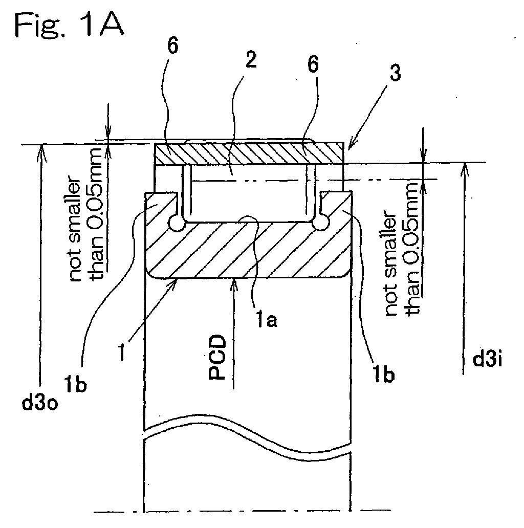
Referring to Figs. 1A and 1B, showing a first preferred embodiment
of the present invention, a roller bearing assembly shown therein includes an
inner race 1 having a raceway surface 1a defined by an outer peripheral surface
of such inner race 1, a circular row of rollers 2 held in rolling contact with the
raceway surface 1a, and a ring-shaped roller retainer 3. The roller retainer 3 is
of a generally ladder-like configuration having a plurality of pockets 4 arranged
in a direction circumferentially thereof. The roller retainer 3 also has pillars 5
each defined between the neighboring pockets 4 and, while the rollers 2 are
accommodated within the respective pockets 4 as seated on the raceway surface
1a, the roller retainer 3 is positioned on one side of the pitch circle of the rollers 2
in the circular row opposite to the raceway surface 1a, with each retainer pillar 5
thereof intervening between the neighboring rollers 2 to thereby retain the rollers
2 in position within the pockets 4 from a direction radially outwardly of the row
of the rollers 2.
The inner race 1 has its opposite ends formed integrally with radially
outwardly extending collars 1b and is prepared by machining a steel material.
On the other hand, the roller retainer 3 is made of an elastically deformable
synthetic resin such as, for example, polyamide (for example, PA66 or PA46) or
polyacetal. If the synthetic resin as a material for the roller retainer 1 is
employed in the form of a non-reinforced synthetic resin or a reinforced synthetic
resin containing reinforcement fibers such as, for example, carbon fibers or glass
fibers, the resultant roller retainer 3 can have a flexibility and a strength
appropriate for the bearing size and the bearing application.
The roller retainer 3 has its opposite axial ends each in the form of a
ring part 6, with the pillars 5 extending axially between the opposite ring parts 6
and equidistantly spaced in a direction circumferentially thereof. A space
between the neighboring pillars 5 defines the pocket 4 for accommodating the
respective roller 2. As best shown in Fig. 1B, each of the pillars 5 of the roller
retainer 3 has such a sectional shape as to have a substantially constant,
maximum width, as measured in a direction circumferentially of the roller
retainer 3, at an outermost diametric portion thereof and a radially inwardly
decreasing width at an inner diametric portion thereof. By way of example,
each retainer pillar 5 represents a generally pentagonal sectional shape with the
inner diametric portion tapering radially inwardly of the circular row of the
rollers 2.
The roller retainer 3 has an outer diameter d3o which is smaller by
0.1 mm or more than the minimum diameter d2o of the circle circumscribing the
circular row of the rollers 2. This difference between the outer diameter d3o
and the diameter d2o of the circumscribed circle is preferably of a value equal to
or greater than 0.1 mm regardless of the size of the roller bearing assembly.
The inner diameter d3i of the circle depicted by and in touch with the inner
diametric portions of the pillars 5 is chosen to be greater than the pitch circle
diameter PCD by, for example, 0.1 mm or more. The extent to which the inner
diameter d3i of the circle depicted by and in touch with the inner diametric
portions of the pillars 5 is greater than the pitch circle diameter PCD may be
chosen to be equal to or greater than a predetermined proportion determined in
consideration with the bearing size.
According to the foregoing embodiment, the pillars 5 of the roller
retainer 3 retains the rollers 2 in position within the pockets 4 from a direction
radially outwardly of the row of the rollers 2 and the inner diameter d3i of the
circle depicted by and in touch with the inner diametric portions of the pillars 5 is
chosen to be greater than the pitch circle diameter PCD. Accordingly, it is
possible to allow the pillars 5 not to exist on the pitch circle represented by the
pitch circle diameter PCD and, therefore, the space between the neighboring
rollers 2, which would increase if each pillar 5 is positioned on the pitch circle,
does not increase and the resultant roller bearing assembly can have the rollers 2
in a number equal to or smaller by one or two than the number of the rollers
employed in the full complement roller bearing. Also, the strength of the pillars
5 can advantageously be secured.
As described above, the roller bearing assembly of the structure
according to the foregoing embodiment of the present invention can exhibit a
non-detachability of the rollers, that is, to enable the roller to be retained
rotatably, but firmly in position, by the use of the roller retainer 3 and can have
the rollers in a number about equal to that in the full complement roller bearing.
Therefore, the various problems inherent in the full component bearing assembly
can advantageously be eliminated substantially. By way of example, the
following advantages can be obtained.
- Even in a bearing assembly using rollers 2 each having opposite flat end
faces, the rollers 2 can be rendered to be non-detachable relative to the inner race
1 and also to the roller retainer.
- Since the rollers 2 each having the opposite flat end faces can be used, the
effective length of each roller can be advantageously set to a maximum available
value within the limited widthwise size.
- No limitation is imposed on the lubricant such as observed with the roller
bearing assembly filled with the thermal curable grease and any lubricant can be
employed as desired.
- Assemblage of the roller bearing assembly of the present invention is easier
than that of the conventional non-detachable full complement roller bearing
assembly.
- User's handling is easier than that of the full component bearing assembly
of a detachable type.
With the roller bearing assembly according to the foregoing
embodiment, the following additional advantages can also be obtained. For
example, since the outer diameter d3o of the roller retainer is chosen to be
smaller by 0.1 mm or more than the minimum diameter d2o of the circle
circumscribing the circular row of the rollers 2, a gap of 0.1 mm or more appears
between a bearing box and the roller retainer 3. Because of this, the roller
retainer 3 does in no way contact the bearing box strongly and, therefore, an
undesirable increase of the frictional torque brought about by the roller retainer 3
can be avoided.
The inner diameter d3i of the circle depicted by and in touch with the
inner diametric portions of the pillars 5 is chosen to be greater than the pitch
circle diameter PCD and the extent to which the inner diameter d3i is increased
relative to the pitch circle diameter PCD is chosen to be 0.1 mm or more.
Accordingly, the space between the neighboring rollers 2 need not be increased
and it is possible to avoid the lack of strength which would otherwise result from
reduction in width of the innermost diametric portion of each of the pillars 5.
Also, since each of the pillars 5 of the roller retainer 3 has such a
sectional shape as to have a substantially constant, maximum width, as measured
in a direction circumferentially of the roller retainer 3, at an outermost diametric
portion thereof and a radially inwardly decreasing width at an inner diametric
portion thereof, each of the pillars 5 can have an increased sectional area with no
need to increase the space between the neighboring rollers 2 and, also, the
lubricity is excellent.
In other words, since the gap between the neighboring members of
the circular row of the rollers 2 represents a generally triangular shape flaring
radially outwardly of the circular row of the rollers 2, increase of the sectional
area of each of the pillars 5 without the space between the neighboring rollers 2
being increased requires the respective retainer pillar 5 to have a substantially
triangular sectional shape tapering in a direction radially inwardly of the circular
row of the rollers 2. However, in the illustrated embodiment, the outermost
diametric portion 5a of each retainer pillar 5, at which the respective retainer
pillar 5 have a maximum width, is fixed at the a substantially constant value
without being expanded in a direction circumferentially of the roller retainer 3,
leaving a space between a surface of the respective roller 2 and a surface of the
respective retainer pillar 5. This unique design is effective to eliminate an
undesirable blockage of the lubricant to thereby minimize reduction of the
lubricity. Also, the pillars 5 will no have any unnecessary, good-for-nothing
portion and, therefore, the amount of the synthetic resin used as a material for the
roller retainer 3 can advantageously be reduced.
Fig. 2 illustrates the roller retainer 3 according to a second preferred
embodiment of the present invention. In this second embodiment, the inner
race 1 is of a drawn cup type, i.e., a press-worked product made of a steel plate.
In addition, the roller retainer 3 has opposite end portions 3a of the inner
peripheral surface thereof so shaped as to be inclined axially outwardly and
upwardly.
Other structural features of the roller retainer 1 shown in Fig. 2 than
those described above are substantially similar to those shown in and described
in connection with the previous embodiment with reference to Figs. 1A and 1B
and, therefore, the details thereof are not reiterated for the sake of brevity.
According to the second embodiment shown in Fig. 2, by allowing
the opposite end portions 3a of the inner peripheral surface of the roller retainer 3
to incline axially outwardly and upwardly, the roller retainer 3 can conveniently
smoothly be inserted into the outside of the circular row of the rollers 2 during
the assemblage, resulting in increase of the assemblability. Also, since the
opposite end portions 3a of the inner peripheral surface of the roller retainer 3 is
inclined axially outwardly and upwardly, the roller retainer 3 can conveniently
smoothly inserted into the outside of the circular row of the rollers 2 from either
one of the directions, i.e., from either leftwards or rightwards as viewed in Fig. 2.
Fig. 3 illustrates the roller retainer 3 according to a third preferred
embodiment of the present invention. According to this third embodiment, the
inner race 1 is in the form of a machined product formed by machining a steel
plate, and the roller retainer 3 is so shaped as to have its axially opposite ring
parts 6 each having a thickness, as measured in a direction radially of the roller
retainer 3, that is greater than that of each of the pillars 5. Other structural
features of the roller retainer 1 shown in Fig. 3 than those described above are
substantially similar to those shown in and described in connection with the
previous embodiment with reference to Figs. 1A and 1B and, therefore, the
details thereof are not reiterated for the sake of brevity.
Even with this design, functions and effects similar to those afforded
by the first embodiment shown in and described with reference to Figs. 1A and
1B can be obtained.
Figs. 4A to 4D and Figs. 5A to 5C illustrates a fourth preferred
embodiment of the present invention. Any of various forms of the roller
retainer 3 according this fourth embodiment is particularly applicable to any one
of the first to third embodiments of the present invention shown in and described
with reference to Figs. 1A and 1B, Fig. 2 and Fig. 3, respectively. As shown in
Figs. 4A to 4D, the roller retainer 3 employed in the roller bearing assembly
according to any one of the first to third embodiments is formed with a plurality
of axial slits 7, 7A at respective locations in a direction circumferentially thereof
so as to extend from one end to a position adjacent the opposite end thereof.
Except for the use of the axial slits 7, 7A, the roller retainer 3 is of the structure
substantially identical with that shown in and described in connection with any
one of the first to third embodiments.
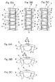
Specifically, Fig. 4A illustrates the roller retainer 3, in which the axial
slits 7 are formed therein so as to extend axially inwardly from one end (a left
end as viewed in Fig. 4A) of the roller retainer 3. In contrast thereto, Fig. 4B
illustrates the roller retainer 3, in which a combination of the odd-numbered axial
slits 7 formed so as to extend axially inwardly from one end of the roller retainer
3 and the even-numbered axial slits 7 formed so as to extend axially inwardly
from the opposite end of the same roller retainer 3 are employed with the
odd-numbered axial slits 7 alternating with the even-numbered axial slits 7 in a
direction circumferentially of the roller retainer 3.
Fig. 4C illustrates the roller retainer 3, in which the axial slits 7 and
7A extend axially inwardly from one end (a left end as viewed in Fig. 4C) thereof,
but in which two types of slits 7 and 7A are employed. Specifically, the axial
slits 7 are comprised of a segment, in which a portion of the ring part 6 between
the neighboring pillars 5 is depleted substantially completely, and a segment
which concurrently serves as a pocket between the neighboring pillars 5. On
the other hand, the axial slits 7A are comprised of a segment, in which a portion
of the ring part 6 between the neighboring pillars 5 is depleted partially at a
location 6a, and a segment which concurrently serves as a pocket between the
neighboring pillars 5. The axial slits 7 and 7A are so formed in the roller
retainer 3 as to alternate with each other in a direction circumferentially of the
roller retainer 3.
Fig. 4D illustrates the roller retainer 3, in which the axial slits 7
extending axially inwardly from one end thereof and the axial slits 7 extending
axially inwardly from the opposite end thereof are employed and alternate with
each other in a direction circumferentially of the roller retainer, allowing the
roller retainer 3 as a whole to represent a generally staggered configuration.
This roller retainer 3 shown in Fig. 4D may be considered similar to that shown
in Fig. 4B, but the dedicated pockets 4 are dispensed.
In any one of the examples shown in Figs. 4A, 4B and 4D, the slits of
the roller retainer 3 includes portions of the ring part 6 each between the
neighboring pillars 5 are depleted substantially completely, and the portions each
concurrently serving as a pocket between the neighboring pillars 5.
In the roller retainer according to any one of the examples shown in
Figs. 4A and 4B, the pockets 4 and the axial slits 7 are so formed as to alternate
with each other with each of the pillars 5 positioned between the pocket 4 and the
slit 7 concurrently serving as a pocket.
In the example shown in Fig. 4C, the axial slits 7A are formed by
opening or slitting an arrangement of the pockets 4 and, in addition to the pillars
5 formed between the pocket 4 and the slits 7 concurrently serving as a pocket 4,
the pillars are also formed between neighboring dedicated pockets although not
shown in Fig. 4C. Even in the examples shown in Figs. 4A and 4B, respectively,
the slits 7 may be formed by opening or slitting an arrangement of the pockets 4.
Each of the pillars 5, whether it is positioned between the pocket 4
and the slit 7 or whether it is positioned between the neighboring dedicated
pockets 4, may be of a shape similar to that described in connection with the first
embodiment with particular reference to Fig. 1B.
Figs. 5A to 5C illustrate different manners of retaining the rollers 2 in
the roller retainer 3 of the structure described above. Specifically, Fig. 5A
illustrates the roller retainer 3 (according to the example shown in Fig. 4A), in
which the axial slits 7 are defined only on one side thereof, with the rollers 2
accommodated within not only the pockets 4, but also the slits 7. This is
particularly advantageous in that the load bearing capacity of the roller bearing
assembly can be increased.
Fig. 5B illustrates the roller retainer 3 (according to the example
shown in Fig. 4B), in which the axial slits 7 are defined on both sides thereof,
with the rollers 2 accommodated within not only the pockets 4, but also the slits
7. Fig. 5C illustrates the roller retainer 3 (according to the example shown in
Fig. 4D, in which only the slits 7 are employed, with the rollers 2 accommodated
within those all slits 7.
In the roller bearing assembly employing the roller retainer 3
according to any one of the respective examples shown in Figs. 4A to 5C,. the
roller retainer 3 are formed with the plural slits 7, 7A cut so as to extend from
one end thereof to a position adjacent the opposite end thereof. Accordingly,
during assemblage of the roller bearing assembly, insertion can readily be
accomplished by radially outwardly expanding a portion of the roller retainer 3
on an insertion side, i.e., one of the opposite ring parts 6 which is oriented
towards the circular row of the rollers 2 during the mounting of the roller retainer
3 on the inner race 1. For this reason, the roller retainer 3 can be deformed
within the limit of elasticity possessed by the material for the roller retainer 3 and,
hence, not only the assemblability but also the precision can advantageously be
increased while the flexure deformation of the roller retainer 3 can be minimized
and the possible reduction of the precision, which would otherwise result from
the deformation, can be avoided. Also, the use of the roller retainer 3 of the
particular design is effective to increase the assemblability of the roller retainer to
thereby increase the precision even though the inner race 1 is in the form of a
machined product as hereinbefore referred to.
Fig. 6 illustrates a fifth preferred embodiment of the present invention.
While in the embodiment shown in Figs. 4A to 5C, the roller retainer 3 has been
shown and described as having the plural slits 7 (7A) deployed in a direction
circumferentially thereof, the roller retainer 3 according to any one of the first to
third embodiments shown and described with reference to Figs. 1A and 1B, Fig.
2 and Fig. 3, respectively, may have a split area 8 at one location thereof in the
circumferential direction thereof as shown in any one of Figs. 6A to 6C.
According to the fifth embodiment, other structural features of the
roller retainer than the use of the slit area 8 in the roller retainer 3 are
substantially similar to those of the roller retainer 3 according to any one of the
first to third embodiments shown and described with reference to Figs. 1A and
1B, Fig. 2 and Fig. 3, respectively.
The split area 8 may be of a design, in which a recess 9a defined in
one end of the divided ring part 6 of the roller retainer 3 can releasably receive
therein a projection 9b defined in the opposite end of the divided ring part 6 as
shown in, for example, Fig. 6A, or the opposite ends of the divided ring part 6
may have respective projections 9c, which form a halving joint, as shown in Fig.
9B. Alternatively, as shown in Fig. 9C, the opposite ends of the divided ring
part 6 may be so shaped as to define a respective flat end face so that the opposite
ends of the divided ring part 6 can be butt-jointed.
Even where the split area 8 is defined in the roller retainer 3 at one
location in the circumferential direction thereof as hereinabove described, one
end of the roller retainer 3 where the split area 8 is defined can be radially
outwardly deformed as is the case with the roller retainer 3 having the slits 7
(7A) defined therein. For this reason, during the assemblage performed in the
manner described hereinbefore, the roller retainer 3 can be inserted outside the
circular row of the rollers 2 without the roller retainer 3 forcibly deformed
considerably, resulting in increase of the assemblability and also increase of the
precision. In a manner similar to the previously described embodiment in
which the rollers 2 are arranged inside the slits 7, 7A, a roller 2 may be arranged
in a pocket equivalent having one side surrounded by the ring part 6 having the
split area 8 defined therein. By so arranging the rollers 2 in the manner
described above, the load bearing capacity of the roller bearing can
advantageously be increased.
Fig. 7 illustrates a sixth preferred embodiment of the present
invention. This sixth embodiment is an example in which the present invention
is applied to the roller bearing assembly having neither an inner raceway nor an
outer raceway. The roller bearing assembly shown therein includes inner and
outer roller retainers 13 and 3, each in the form of a ring having a plurality of
pockets 4 defined therein in a direction circumferentially thereof, and a circular
row of rollers 2 operatively accommodated within the respective pockets defined
in each of the inner and outer roller retainers 13 and 3. The inner roller retainer
13 is positioned on a radially inner side of the pitch circle of the rollers 2, with
each retainer pillar 5 thereof intervening between the neighboring rollers 2 to
thereby retain the rollers 2 in position within the pockets 4 from a direction
radially inwardly of the row of the rollers 2. On the other hand, the outer roller
retainer 3 is similar in structure and function to that described in connection with
any of the previous embodiments and is positioned on a radially outer side of the
pitch circle of the rollers 2, with each retainer pillar 5 thereof intervening
between the neighboring rollers 2 to thereby retain the rollers 2 in position within
the pockets 4 from the direction radially outwardly of the row of the rollers 2.
Each of the inner and outer roller retainers 13 and 3 is made of an
elastically deformable synthetic resin such as, for example, polyamide (for
example, PA66 or PA46) or polyacetal. If the synthetic resin as a material for
the roller retainer 1 is employed in the form of a non-reinforced synthetic resin or
a reinforced synthetic resin containing reinforcement fibers such as, for example,
carbon fibers or glass fibers, the resultant roller retainer 3 can have a flexibility
and a strength appropriate for the bearing size and the bearing application.
Each of the inner and outer roller retainers 13 and 3 has its opposite
axial ends each in the form of a ring part 6, with the pillars 5 extending axially
between the opposite ring parts 6 and equidistantly spaced in a direction
circumferentially thereof. A space between the neighboring pillars 5 in each of
the inner and outer roller retainers 13 and 3 defines the pocket 4 for
accommodating the respective roller 2.
As best shown in Fig. 7B, the inner roller retainer 13 has an inner
diameter d13i which is greater by 0.1 mm or more than the maximum diameter
d2i of the circle inscribing the circular row of the rollers 2. This difference
between the inner diameter d13i and the diameter d2i of the inscribed circle is
preferably of a value equal to or greater than 0.1 mm regardless of the size of the
roller bearing assembly. The outer diameter d13o of the circle depicted by and
in touch with outermost diametric portions of the pillars 5 is chosen to be smaller
than the pitch circle diameter PCD by, for example, 0.1 mm or more. The
extent to which the outer diameter d13o of the circle depicted by and in touch
with the outermost diametric portions of the pillars 5 is smaller than the pitch
circle diameter PCD may be chosen to be equal to or greater than a
predetermined proportion determined in consideration with the bearing size.
Each of the pillars 5 of the inner roller retainer 13 has a width B which is
preferably within the range of 15 to 30% of the diameter of each roller 2.
With respect to the outer roller retainer 3, it may be substantially
identical with that shown in and described in connection with the first
embodiment with reference to Figs. 1A to 1B. Specifically, the outer diameter
d3o of the outer roller retainer 3 is smaller by 0.1 mm or more than the minimum
diameter d2o of the circle circumscribing the circular row of the rollers 2. This
difference between the outer diameter d3o and the diameter d2o of the
circumscribed circle is preferably of a value equal to or greater than 0.1 mm
regardless of the size of the roller bearing assembly. The inner diameter d3i of
the circle depicted by and in touch with the innermost diametric portions of the
pillars 5 is chosen to be greater than the pitch circle diameter PCD by, for
example, 0.1 mm or more. The extent to which the inner diameter d3i of the
circle depicted by and in touch with the innermost diametric portions of the
pillars 5 is greater than the pitch circle diameter PCD may be chosen to be equal
to or greater than a predetermined proportion determined in consideration with
the bearing size.
Each of the pillars 5 of the inner roller retainer 13 has such a sectional
shape as to have a substantially constant, maximum width, as measured in a
direction circumferentially of the inner roller retainer 13, at the innermost
diametric portion 5c thereof and a radially outwardly decreasing width at the
outer diametric portion 5d thereof. A top of the outer diametric portion 5d of
each retainer pillar 5 of the inner roller retainer 13 may be angled or rounded.
On the other hand, each retainer pillar 5 of the outer roller retainer 3 may have a
square or pentagonal sectional shape.
According to the foregoing embodiment shown in and described with
reference to Figs. 7A and 7B, since the circular row of the rollers 2 are retained
by the inner and outer roller retainers 13 and 3, a non-detachable type roller,
bearing assembly being a retainer type roller bearing assembly having no
raceway, can be obtained, in which the rollers 2 will not drop off or separate from
each other prior to the roller bearing assembly incorporated in a machine or
equipment. Considering that the respective pillars 5 of the inner and outer roller
retainers 13 and 3, while intervening between the neighboring rollers 2,
cooperate with each other to retain the rollers 2 in position within the pockets 4
in the inner and outer races 13 and 3 from directions radially inwardly and
outwardly of the row of the rollers 2, respectively, and that the outer diameter
d13o of the circle depicted by and in touch with the outermost diametric portions
5d of the pillars 5 of the inner retainers 13 is chosen to be smaller than the pitch
circle diameter PCD and the inner diameter d3i of the circle depicted by and in
touch with the innermost diametric portions of the pillars 5 of the outer roller
retainers 3 is chosen to be greater than the pitch circle diameter PCD, the
respective pillars 5 of the inner and outer roller retainers 13 and 3 do in no way
exist on the pitch circle having the diameter PCD.
For the above reason, the space between the neighboring rollers 2,
which would increase if each pillar 5 is positioned on the pitch circle, does not
increase and the resultant roller bearing assembly can have the rollers 2 in a
number about equal to the number of the rollers employed in the full complement
roller bearing, even though the roller bearing assembly is of a non-detachable
type utilizing the inner and outer roller retainers 13 and 3. Also, as compared
with the conventional roller bearing assembly, having the inner race, of the same
sectional height, a relatively large load bearing capacity can be exhibited.
Accordingly, the various problems hitherto encountered with the full complement
roller bearing can advantageously be eliminated substantially and, for example,
the roller bearing assembly embodying the present invention as shown in Figs.
7A and 7B can be assembled with a minimized number of assembling steps and
with no drop-off preventing sleeve being employed.
For substantially eliminating the various problems hitherto
encountered with the full complement roller bearing, the following various
advantages can be obtained as is the case with any one of the previously
described embodiments:
- Even in a bearing assembly using rollers 2 each having opposite flat end
faces, the rollers 2 can be rendered to be non-detachable relative to the roller
retainer.
- Since the rollers 2 each having the opposite flat end faces can be used, the
effective length of each roller can be advantageously set to a maximum available
value within the limited widthwise size.
- No limitation is imposed on the lubricant such as observed with the roller
bearing assembly filled with the thermal curable grease and any lubricant can be
employed as desired.
- Assemblage of the roller bearing assembly of the present invention is easier
than that of the conventional non-detachable full complement roller bearing
assembly.
- User's handling is easier than that of the full component bearing assembly
of a detachable type.
With the roller bearing assembly according to the foregoing
embodiment shown in and described with particular reference to Figs. 7A and 7B,
the following additional advantages can also be obtained. For example, since
the outer diameter d3o of the outer roller retainer 3 is chosen to be smaller by 0.1
mm or more than the minimum diameter d2o of the circle circumscribing the
circular row of the rollers 2, a gap of 0.1 mm or more appears between a bearing
box and the outer roller retainer 3. Because of this, the roller retainer 3 does in
no way contact the bearing box strongly and, therefore, an undesirable increase
of the frictional torque brought about by the outer roller retainer 3 can be
avoided.
The inner diameter d13i of the circle depicted by and in touch with
the innermost diametric portions 5c of the inner roller retainer 13 is chosen to be
greater by 0.1 mm or more than the maximum value of the diameter d2i of the
circle inscribing the circular row of the rollers 2, a gap of 0.1 mm or more
appears between a shaft and the inner roller retainer 13. Because of this, the
inner roller retainer 13 does in no way contact the shaft strongly and, therefore,
an undesirable increase of the frictional torque brought about by the inner roller
retainer 13 can be avoided.
Also, since the inner diameter d3i of the circle depicted by and in
touch with the innermost diametric portions of the pillars 5 of the outer roller
retainer 3 is chosen to be greater than the pitch circle diameter PCD and the
extent to which the inner diameter d3i is increased relative to the pitch circle
diameter PCD is chosen to be 0.1 mm or more, the space between the
neighboring rollers 2 need not be increased and it is possible to avoid the lack of
strength which would otherwise result from reduction in width of the innermost
diametric portion of each of the pillars 5.
Moreover, since the outer diameter d13o of the circle depicted by and
in touch with outermost diametric portions of the pillars 5 of the inner roller
retainer 13 is chosen to be smaller than the pitch circle diameter PCD and the
extent to which the outer diameter d13o of the circle depicted by and in touch
with the outermost diametric portions of the pillars 5 is smaller than the pitch
circle diameter PCD is chosen to be equal to or greater than 0.1 mm, the space
between the neighboring rollers 2 need not be increased and it is possible to
avoid the lack of strength which would otherwise result from reduction in width
of the outermost diametric portion of each of the pillars 5.
In addition, since each of the pillars 5 of the inner roller retainer 13
has such a sectional shape as to have a substantially constant, maximum width, as
measured in a direction circumferentially of the inner roller retainer 3, at the
innermost diametric portion 5c thereof and the radially outwardly decreasing
width at the outer diametric portion 5d thereof positioned radially outwardly of
the innermost diametric portion 5c, each of the pillars 5 can have an increased
sectional area with no need to increase the space between the neighboring rollers
2 and, also, the lubricity is excellent. In other words, since the gap between the
neighboring members of the circular row of the rollers 2 represents a generally
triangular shape flaring radially inwardly of the circular row of the rollers 2,
increase of the sectional area of each of the pillars 5 without the space between
the neighboring rollers 2 being increased requires the respective retainer pillar 5
to have a substantially triangular sectional shape tapering in a direction radially
outwardly. However, in the illustrated embodiment, the innermost diametric
portion 5c of each retainer pillar 5, at which the respective retainer pillar 5 have a
maximum width, is fixed at the a substantially constant value without being
expanded in a direction circumferentially of the roller retainer 3, leaving a space
between a surface of the respective roller 2 and a surface of the respective
retainer pillar 5. This unique design is effective to eliminate an undesirable
blockage of the lubricant to thereby minimize reduction of the lubricity. Also,
the pillars 5 will no have any unnecessary, good-for-nothing portion and,
therefore, the amount of the synthetic resin used as a material for the roller
retainer 3 can advantageously be reduced.
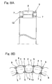
Figs. 8A and 8B illustrate a seventh preferred embodiment of the
present invention. The roller bearing assembly according to this seventh
embodiment is substantially similar to that according to the sixth embodiment
shown in and described with reference to Figs. 7A and 7B, except that in the
embodiment of Figs. 8A and 8B each of the inner and outer roller retainers 13
and 3 is of a structure, in which axial slits 7 are formed so as to extend from one
end to a position adjacent the opposite end thereof in a manner substantially as
shown in Fig. 4D. In this embodiment, the inner and outer roller retainers 13
and 3 are so positioned relative to the circular row of the rollers 2 that the axial
slits 7 in one of the inner and outer roller retainers 13 and 3 are displaced in
phase relative to the axial slits in the other of the inner and outer roller retainers
13 and 3 in a direction circumferentially of the circular row of the rollers 2. It is
to be noted that the structure of the slits 7 in each of the inner and outer roller
retainers 13 and 3 may not be always limited to such as shown in Fig. 4D, but
may be such as shown in any one of Figs. 4A to 4C.
Other structural features of the roller bearing assembly according to
the seventh embodiment than those described above are substantially similar to
those shown in and described with reference to Figs. 7A and 7B and, accordingly,
the details thereof are not reiterated for the sake of brevity.
According to the seventh embodiment, the use of the axial slits 7 in
each of the inner and outer roller retainers 13 and 3 is effective to allow that
portion of the outer roller retainer 3 on the insertion side, i.e., one of the opposite
ring parts 6 which is oriented towards the circular row of the rollers 2, to be
radially outwardly expanded and, also, to allow that portion of the inner roller
retainer 13 similarly on the insertion side to be radially inwardly constricted, to
facilitate retention of the rollers 2 by the respective outer and inner roller
retainers 13 and 3.
Also, since the inner and outer roller retainers 13 and 3 are so
positioned relative to the circular row of the rollers 2 that the axial slits 7 in the
inner roller retainer 13 are displaced in phase relative to the axial slits 7 in the
outer roller retainer 3 in a direction circumferentially of the circular row of the
rollers 2 as hereinbefore described, a sufficient retaining strength, with which the
rollers 2 can be retained by the inner and outer roller retainers 13 and 3, can be
secured effectively.
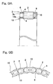
Figs. 9A and 9B illustrate an eighth preferred embodiment of the
present invention. The roller bearing assembly shown in Fig. 9 is substantially
similar to that shown in and described with reference to Figs. 7A and 7B, except
that in this embodiment of Figs. 9A and 9B the inner and outer roller retainers 13
and 3 are partially integrated together by means of a plurality of
circumferentially spaced connecting segments 10 each extending from one end of
the outer roller retainer 3 to the adjacent end of the inner roller retainer 13. The
number of the connecting segments 10 employed may be one for three rollers 2
as best shown in Fig. 9B. Each of the connecting segments 10 is so shaped as to
allow a region, bound between the respective ring parts 6 of the inner and outer
roller retainers 13 and 3 and between the neighboring connecting segments 10, to
represent a generally elliptic widow 11.
Respective opposite ends of the outer and inner roller retainers 13 and
3 remote from the connecting segments 10 are left unconnected and are axially
outwardly tapered as at 13a and 3a, respectively. In other words, an end edge 3a
of an inner peripheral surface of the outer roller retainer 3 remote from the
connecting segments 10 and an end edge 13a of an outer peripheral surface of the
inner roller retainer 13 remote from the connecting segments 10 and adjacent the
outer end edge 3 a are axially outwardly tapered.
Connection of the inner and outer roller retainers 13 and 3 by means
of the circumferentially spaced connecting segments 10 is effective to facilitate a
job of inserting the inner and outer roller retainers 13 and 3 radially inwardly and
outwardly of the circular row of the rollers 2 during the assemblage. Also,
since the respective end edges 13a and 3a of the inner and outer roller retainers
13 and 3 remote from the connecting segments 10 are axially tapered, the
insertion of the inner and outer roller retainers 13 and 3 towards the circular row
of the rollers 2 with the tapered end edges 13a and 3a oriented towards the
circular row of the rollers 2 can readily and smoothly be accomplished.
Figs. 10A and 10B illustrate a ninth preferred embodiment of the
present invention. The roller bearing assembly best shown in Fig. 10A is
substantially similar to that shown in and described with reference to Figs. 9A
and 9B, except for in this embodiment of Figs. 10A and 10B, the connecting
segment 10 is employed for each of the rollers 2 in the circular row and is so
shaped as to allow a region, bound between the respective ring parts 6 of the
inner and outer roller retainers 13 and 3 and between the neighboring connecting
segments 10, to represent a generally rectangular widow 11.
Also, the roller bearing assembly best shown in Fig. 10B is
substantially similar to that shown in and described with reference to Figs. 9A
and 9B, except for in this embodiment of Figs. 10A and 10B, the connecting
segment 10 is employed for two of the rollers 2 and is so shaped as to represent
an outwardly flared fan shape from the ring part 6 of the inner roller retainer 13
towards the ring part 6 of the outer roller retainer 3. The connecting segment 10
may be so shaped as to represent an outwardly tapered fan shape from the ring
part 6 of the inner roller retainer 13 towards the ring part 6 of the outer roller
retainer 3.
Although the present invention has been fully described in connection
with the preferred embodiments thereof with reference to the accompanying
drawings which are used only for the purpose of illustration, those skilled in the
art will readily conceive numerous changes and modifications within the
framework of obviousness upon the reading of the specification herein presented
of the present invention. Accordingly, such changes and modifications are,
unless they depart from the scope of the present invention as delivered from the
claims annexed hereto, to be construed as included therein.