EP1574718A1 - Centrifugal blower and air conditioner with the same - Google Patents
Centrifugal blower and air conditioner with the same Download PDFInfo
- Publication number
- EP1574718A1 EP1574718A1 EP03774113A EP03774113A EP1574718A1 EP 1574718 A1 EP1574718 A1 EP 1574718A1 EP 03774113 A EP03774113 A EP 03774113A EP 03774113 A EP03774113 A EP 03774113A EP 1574718 A1 EP1574718 A1 EP 1574718A1
- Authority
- EP
- European Patent Office
- Prior art keywords
- air
- centrifugal fan
- hub
- rotary shaft
- electric motor
- Prior art date
- Legal status (The legal status is an assumption and is not a legal conclusion. Google has not performed a legal analysis and makes no representation as to the accuracy of the status listed.)
- Withdrawn
Links
Images






Classifications
-
- F—MECHANICAL ENGINEERING; LIGHTING; HEATING; WEAPONS; BLASTING
- F04—POSITIVE - DISPLACEMENT MACHINES FOR LIQUIDS; PUMPS FOR LIQUIDS OR ELASTIC FLUIDS
- F04D—NON-POSITIVE-DISPLACEMENT PUMPS
- F04D25/00—Pumping installations or systems
- F04D25/02—Units comprising pumps and their driving means
- F04D25/08—Units comprising pumps and their driving means the working fluid being air, e.g. for ventilation
- F04D25/082—Units comprising pumps and their driving means the working fluid being air, e.g. for ventilation the unit having provision for cooling the motor
-
- F—MECHANICAL ENGINEERING; LIGHTING; HEATING; WEAPONS; BLASTING
- F04—POSITIVE - DISPLACEMENT MACHINES FOR LIQUIDS; PUMPS FOR LIQUIDS OR ELASTIC FLUIDS
- F04D—NON-POSITIVE-DISPLACEMENT PUMPS
- F04D29/00—Details, component parts, or accessories
- F04D29/26—Rotors specially for elastic fluids
- F04D29/28—Rotors specially for elastic fluids for centrifugal or helico-centrifugal pumps for radial-flow or helico-centrifugal pumps
-
- F—MECHANICAL ENGINEERING; LIGHTING; HEATING; WEAPONS; BLASTING
- F04—POSITIVE - DISPLACEMENT MACHINES FOR LIQUIDS; PUMPS FOR LIQUIDS OR ELASTIC FLUIDS
- F04D—NON-POSITIVE-DISPLACEMENT PUMPS
- F04D29/00—Details, component parts, or accessories
- F04D29/26—Rotors specially for elastic fluids
- F04D29/28—Rotors specially for elastic fluids for centrifugal or helico-centrifugal pumps for radial-flow or helico-centrifugal pumps
- F04D29/281—Rotors specially for elastic fluids for centrifugal or helico-centrifugal pumps for radial-flow or helico-centrifugal pumps for fans or blowers
-
- F—MECHANICAL ENGINEERING; LIGHTING; HEATING; WEAPONS; BLASTING
- F04—POSITIVE - DISPLACEMENT MACHINES FOR LIQUIDS; PUMPS FOR LIQUIDS OR ELASTIC FLUIDS
- F04D—NON-POSITIVE-DISPLACEMENT PUMPS
- F04D29/00—Details, component parts, or accessories
- F04D29/58—Cooling; Heating; Diminishing heat transfer
-
- F—MECHANICAL ENGINEERING; LIGHTING; HEATING; WEAPONS; BLASTING
- F04—POSITIVE - DISPLACEMENT MACHINES FOR LIQUIDS; PUMPS FOR LIQUIDS OR ELASTIC FLUIDS
- F04D—NON-POSITIVE-DISPLACEMENT PUMPS
- F04D29/00—Details, component parts, or accessories
- F04D29/58—Cooling; Heating; Diminishing heat transfer
- F04D29/5806—Cooling the drive system
-
- F—MECHANICAL ENGINEERING; LIGHTING; HEATING; WEAPONS; BLASTING
- F24—HEATING; RANGES; VENTILATING
- F24F—AIR-CONDITIONING; AIR-HUMIDIFICATION; VENTILATION; USE OF AIR CURRENTS FOR SCREENING
- F24F1/00—Room units for air-conditioning, e.g. separate or self-contained units or units receiving primary air from a central station
- F24F1/0007—Indoor units, e.g. fan coil units
- F24F1/0018—Indoor units, e.g. fan coil units characterised by fans
- F24F1/0022—Centrifugal or radial fans
-
- F—MECHANICAL ENGINEERING; LIGHTING; HEATING; WEAPONS; BLASTING
- F24—HEATING; RANGES; VENTILATING
- F24F—AIR-CONDITIONING; AIR-HUMIDIFICATION; VENTILATION; USE OF AIR CURRENTS FOR SCREENING
- F24F1/00—Room units for air-conditioning, e.g. separate or self-contained units or units receiving primary air from a central station
- F24F1/0007—Indoor units, e.g. fan coil units
- F24F1/0043—Indoor units, e.g. fan coil units characterised by mounting arrangements
- F24F1/0047—Indoor units, e.g. fan coil units characterised by mounting arrangements mounted in the ceiling or at the ceiling
-
- F—MECHANICAL ENGINEERING; LIGHTING; HEATING; WEAPONS; BLASTING
- F24—HEATING; RANGES; VENTILATING
- F24F—AIR-CONDITIONING; AIR-HUMIDIFICATION; VENTILATION; USE OF AIR CURRENTS FOR SCREENING
- F24F1/00—Room units for air-conditioning, e.g. separate or self-contained units or units receiving primary air from a central station
- F24F1/0007—Indoor units, e.g. fan coil units
- F24F1/0059—Indoor units, e.g. fan coil units characterised by heat exchangers
- F24F1/0063—Indoor units, e.g. fan coil units characterised by heat exchangers by the mounting or arrangement of the heat exchangers
Definitions
- the present invention relates to a centrifugal fan and an air conditioner provided therewith, and more particularly relates to a centrifugal fan that sucks in air from the rotary shaft direction and blows out air in a direction that intersects the rotary shaft, and an air conditioner provided therewith.
- centrifugal fans provided in air conditioners and the like have been designed to promote cooling of fan motors in order to prevent overheating of fan motors during operation.
- the air conditioner includes a casing that houses various constituent equipment, and a decoration panel arranged on the lower side of the casing.
- An air inlet is provided at the approximate center of the decoration panel.
- the casing is provided therein with a centrifugal fan that sucks in air from the air inlet and blows it out in the outer peripheral direction, and a heat exchanger arranged so that it surrounds the outer periphery of the centrifugal fan.
- the centrifugal fan has a fan motor that is fixed at the approximate center of the top plate of the casing, and an impeller that is rotationally driven by the fan motor.
- the impeller principally includes a hub that is coupled to the shaft of the fan motor, a shroud that is arranged spaced apart by a prescribed spacing on the side opposite the fan motor of the hub (namely, the air inlet side), and a plurality of blades arranged between the hub and the shroud and arrayed in the circumferential direction.
- An opening is provided at the approximate center of the shroud so that it opposes the air inlet.
- the hub has a plurality of cooling air holes positioned on the outer peripheral side of the shaft and the inner peripheral side of the plurality of blades.
- the inner peripheral part of the hub bulges towards the side opposite the fan motor, and the fan motor is arranged so that it opposes that bulged portion.
- a hub cover is provided on the surface of the hub on the side opposite the fan motor that covers the cooling air holes in a state spaced apart by a prescribed spacing from the hub.
- the surface of the hub cover on the hub side has a plurality of guide blades provided so that they protrude radially.
- the abovementioned conventional centrifugal fan can increase the quantity of air blown out from the cooling air holes by radial guide blades provided in the hub cover, but there is a tendency for the noise level to increase.
- the centrifugal fan as recited in Claim 1 is a centrifugal fan that sucks in air from a rotary shaft direction and blows air out in a direction that intersects a rotary shaft, including an electric motor, a main plate, a plurality of blades, and an air guide.
- the electric motor has the rotary shaft.
- the main plate has a cooling air hole and is coupled to and rotationally driven by the rotary shaft.
- the plurality of blades are provided on the surface of the main plate on the side opposite the electric motor and at a position on the outer peripheral side of the radial position of the cooling air hole.
- the air guide after a portion of the blown out air has been guided to the vicinity of the electric motor and has cooled the electric motor, guides the air flow so that the revolving direction velocity decreases when blown out from the cooling air hole to the side of the main plate opposite the electric motor.
- the air guide is a radial guide blade that is provided in the hub cover and, consequently the quantity of air sucked in from the cooling air hole tends to increase due to the resulting ventilation action, but the noise level also tends to increase.
- the present inventors discovered that this noise is caused by turbulence in the flow when the air sucked in from the cooling air hole merges with the air sucked in from the air inlet side (the rotary shaft direction). Specifically, it was due to the following types of causes.
- the air sucked in from the rotary shaft direction flows toward the rotary shaft direction as far as the vicinity of the main plate, and then the direction of the flow changes to the outer peripheral direction due to the rotation of the plurality of blades. At this time, the air sucked in from the rotary shaft direction flows as far as the vicinity of the front edge part of the blade with a revolving direction velocity of nearly zero.
- the air blown out from the cooling air hole is scooped out by the plurality of blades and blown out toward the outer peripheral side, it has a revolving direction velocity in the rotational direction.
- the present invention provides an air guide that, when the air that passed through the vicinity of the electric motor is blown out from the cooling air hole to the side of the main plate opposite the electric motor, guides the air so that the revolving direction velocity decreases. Thereby, the air used to cool the electric motor can be merged along the air flow sucked in from the rotary shaft direction, and the increase in the noise level can therefore be suppressed.
- the centrifugal fan as recited in Claim 2 is a centrifugal fan that sucks in air from a rotary shaft direction and blows air out in a direction that intersects a rotary shaft, including an electric motor, a main plate, a plurality of blades, and an air guide.
- the electric motor has the rotary shaft.
- the main plate has a cooling air hole and is coupled to and rotationally driven by the rotary shaft.
- the plurality of blades are provided on the surface of the main plate on the side opposite the electric motor and at a position on the outer peripheral side of the radial position of the cooling air hole.
- the air guide after a portion of the blown out air has been guided to the vicinity of the electric motor and has cooled the electric motor, guides the air flow so that it is blown out toward the side of the main plate in the counter rotational direction when blown out from the cooling air hole to the side of the main plate opposite the electric motor.
- the air guide is a radial guide blade that is provided in the hub cover and, consequently the quantity of air sucked in from the cooling air hole increases due to the resulting ventilation action, but the noise level also tends to increase.
- the present inventors discovered that this noise is caused by turbulence in the flow when the air sucked in from the cooling air hole merges with the air sucked in from the air inlet side (the rotary shaft direction). Specifically, it was due to the following types of causes.
- the air sucked in from the rotary shaft direction flows toward the rotary shaft direction as far as the vicinity of the main plate, and then the direction of the flow changes to the outer peripheral direction due to the rotation of the plurality of blades. At this time, the air sucked in from the rotary shaft direction flows as far as the vicinity of the front edge part of the blades with a revolving direction velocity of nearly zero. However, because the air blown out from the cooling air hole is scooped out by the plurality of blades and blown out toward the outer peripheral side, it has a revolving direction velocity in the rotational direction.
- the present invention provides an air guide that guides the air that passed through the vicinity of the electric motor so that it is blown out from the cooling air hole to the side of the main plate in the counter rotational direction with respect to the main plate.
- the centrifugal fan as recited in Claim 3 is the centrifugal fan as recited in Claim 1 or Claim 2, wherein the air guide is formed integrated with the main plate.
- Forming the air guide integrally with the main plate in the centrifugal fan enables a reduction in the number of parts.
- the centrifugal fan as recited in Claim 4 is the centrifugal fan as recited in Claim 2, further including a cover that covers the cooling air hole from the side opposite the electric motor, and that is provided so that it rotates integrally with the main plate.
- the air guide is formed between the cover and the main plate.
- the centrifugal fan as recited in Claim 5 is the centrifugal fan as recited in Claim 4, wherein the air guide has a blade shape inclined rearwards in the rotational direction of the cover.
- the centrifugal fan as recited in Claim 6 is the centrifugal fan as recited in Claim 5, wherein the air guide has a volute blade shape.
- the centrifugal fan as recited in Claim 7 is the centrifugal fan as recited in any one claim of Claim 4 through Claim 6 wherein the air guide is formed in the cover.
- the air guide in the centrifugal fan is formed in a cover that is a member separate from the main plate, an increase in the noise level can be suppressed without changing the structure of the conventional main plate.
- the air conditioner as recited in Claim 8 includes the centrifugal fan as recited in any one claim of Claim 1 through Claim 7, a heat exchanger arranged on the outer peripheral side of the centrifugal fan, and a casing that houses the centrifugal fan and the heat exchanger.
- the present air conditioner is provided with a centrifugal fan, wherein an air guide is provided that, when the air that passed through the vicinity of the electric motor is blown out from the cooling air hole to the side of the main plate opposite the electric motor, guides the air so that the revolving direction velocity decreases, and an increase in the noise level can therefore be suppressed.
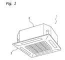
- FIG. 1 shows an exterior perspective view (ceiling is omitted) of an air conditioner 1 provided with a centrifugal fan 4 according to the first embodiment of the present invention.
- the air conditioner 1 is a ceiling embedded type, and includes a casing 2 that houses various constituent equipment therein, and a decoration panel 3 arranged on the lower side of the casing 2.
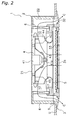
- the casing 2 of the air conditioner 1 is arranged and inserted in the opening formed in a ceiling U in the air conditioned room, as shown in FIG. 2.
- the decoration panel 3 is fitted into the ceiling U opening.
- the casing 2 has a top plate 21, and a side plate 22 that extends downward from the peripheral edge part of the top plate 21.
- the centrifugal fan 4 is arranged inside the casing 2.
- the centrifugal fan 4 is a turbofan, and has a fan motor 41 (electric motor) provided at the center part of the top plate 21 of the casing 2, and a turbo impeller 42 that is coupled to and rotationally driven by a shaft 41a (rotary shaft) of the fan motor 41.
- the turbo impeller 42 has a disc-shaped hub 43 (main plate) that is coupled to the shaft 41 a of the fan motor 41, a plurality of blades 44 provided at the outer peripheral part of the surface on the lower side of the hub 43 (namely, the surface on the side opposite the fan motor 41), and a disc-shaped shroud 45 that is provided on the lower side of the blades 44 and has an opening in the center part.
- the inner peripheral part of the hub 43 bulges toward the side opposite the fan motor, and the fan motor 41 is arranged so that it opposes that bulged part.
- the centrifugal fan 4 is constituted so that the rotation of the plurality of blades 44 sucks in air from the lower side of the turbo impeller 42 into the air conditioned room through the opening of the shroud 45, and blows out that sucked-in air to the outer peripheral side of the turbo impeller 42.
- a fan motor cooling mechanism 51 for cooling the fan motor 41 is provided in the hub 43 of the turbo impeller 42, and these details are discussed later.
- a bell mouth 5 for guiding the air to the centrifugal fan 4 is arranged on the lower side of the centrifugal fan 4.
- a heat exchanger 6 is arranged on the outer peripheral side of the centrifugal fan 4 so that it encircles the centrifugal fan 4.
- the heat exchanger 6 is connected via a coolant conduit to a heat source unit that is installed, for example, outdoors.
- the heat exchanger 6 functions as an evaporator during air conditioning operation, and as a condenser during heating operation, and can thereby control the temperature of the air blown out from the centrifugal fan 4.
- a drain pan 7 is arranged on the lower side of the heat exchanger 6 for receiving the drain water generated by the condensation of moisture in the air in the heat exchanger 6.
- a casing heat insulating material 8 is arranged so that it is interposed between an upper end part of the heat exchanger 6 and the top plate 21 of the casing 2.
- the casing heat insulating material 8 extends from between the upper end part of the heat exchanger 6 and the top plate 21 of the casing 2 toward the outer side, and is arranged so that it encircles the entire inner surface of the side plate 22 of the casing 2. This prevents heat loss to the exterior from the top plate 21 and the side plate 22 of the casing 2, condensation of the casing 2, and the like.
- the decoration panel 3 arranged on the lower side of the casing 2 has an air inlet 31 formed at the center part thereof, and a plurality (e.g., four) of air outlets 32 formed at the side edge part thereof.
- a filter 33 is provided in the air inlet 31 of the decoration panel 3 in order to eliminate dust in the air sucked in from the air inlet 31.
- a panel heat insulating material 9 is provided between the upper end part of the decoration panel 3 and the lower end part of the casing 2.
- a main air passageway 10 is formed in the air conditioner 1 from the air inlet 31 of the decoration panel 3 to the air outlets 32 via the filter 33, the bell mouth 5, the centrifugal fan 4, and the heat exchanger 6.
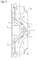
- FIG. 3 is an enlarged view of the centrifugal fan 4 in FIG. 2.
- FIG. 4 is an auxiliary view taken along A in FIG. 3.
- FIG. 5 is a cross-sectional view taken along B-B in FIG. 4.
- an arrow R in FIG. 4 depicts the rotational direction of the turbo impeller 42 (i.e., the hub 43) of the centrifugal fan 4.
- the motor cooling mechanism 51 has a cooling air hole 43a, and an air guide 52 provided corresponding to the cooling air hole 43a.
- the cooling air hole 43a is a hole provided in the hub 43 for guiding to the vicinity of the fan motor 41 a portion of the air blown out toward the outer peripheral side by the turbo impeller 42.
- the cooling air hole 43a is a long hole and a plurality thereof (five holes in the present embodiment) are formed arrayed concentrically with the hub 43.
- the cooling air holes 43a are formed on the inner peripheral side of the radial position of the blades 44.
- the air guide 52 can guide the air that flows from the upper surface side of the cooling air holes 43a (fan motor side) to the lower surface side of the hub 43 so that it blows out in the counter R direction.
- the air guide 52 is a half-pipe shaped part provided so that it covers each of the cooling air holes 43a from the lower surface side of the hub 43 (the air inlet side), and an opening is formed in the counter R direction side thereof.
- the air guide 52 is formed integrated with the hub 43.
- the fan motor 41 when operation starts, the fan motor 41 is driven, and the turbo impeller 42 of the centrifugal fan 4 rotates.
- refrigerant also circulates in the heat exchanger 6.
- the heat exchanger 6 functions as an evaporator during cooling operation, and as a condenser during heating operation.
- the air inside the air conditioned room is sucked in from the lower side of the centrifugal fan 4 from the air inlet 31 of the decoration panel 3 via the filter 33 and the bell mouth 5.
- This air is blown out toward the outer periphery side by the turbo impeller 42, reaches the heat exchanger 6, is cooled or heated in the heat exchanger 6, and is then blown out toward the room interior from each of the air outlets 32, thereby either cooling or heating the room interior (refer to the arrow C in FIG. 2 and FIG. 3).
- the air that passes through this branch air passageway 11 reaches the vicinity of the fan motor 41, and its temperature is raised by the action of cooling the fan motor 41 (refer to the arrow E in FIG. 3).
- the air used to cool the fan motor 41 returns to the main air passageway 10 from the cooling air holes 43a and the air guide 52 formed in the hub 43, and merges with the air flow (refer to the arrow C in FIG. 3) that is sucked in from the air inlet 31 and flows in the main air passageway 10 (refer to the arrow F in FIG. 3).
- the air that blew out toward the outer peripheral side from the turbo impeller 42 has a revolving direction velocity in the R direction, as shown in FIG. 4, is consequently introduced to the branch air passageway 11, passes through the vicinity of the fan motor 41 and, furthermore, has a revolving direction velocity in the R direction even when it returns from the cooling air holes 43a to the main air passageway 10 (refer to the arrows D, E, F in FIG. 4).
- the air guide 52 is open on the counter R direction side, the air that passes through the vicinity of the fan motor 41 is blown out from the cooling air holes 43a to the main air passageway 10 side, at which time it is guided so that its revolving direction velocity decreases. Specifically, as shown in FIG. 4, the flow of the air that passes through the cooling air holes 43a is changed to a flow in the counter R direction with respect to the hub 43 (refer to the arrow F in FIG. 5) by the air guide 52, and forms a flow having a velocity vector F 1 with respect to the hub 43.
- the hub 43 rotates in the R direction and, as a result, this air flow forms a flow having a velocity vector F 3 that combines a velocity vector F 2 and velocity vector F 1 corresponding to the rotational velocity of the hub 43, and blows out on the main air passageway 10 side.
- the air guide 52 functions so that the air flow (arrow F) that returns from the cooling air holes 43a to the main air passageway 10 cancels out the revolving direction velocity in the R direction that it has when it flows into the air guide 52. Further, the air flow (arrow F) is formed so that it smoothly merges with the air flow (arrow C) that is sucked in from the air inlet 31 and flows with a nearly zero revolving direction velocity as far as the vicinity of the front edge part of the blade 44.
- the centrifugal fan 4 of the air conditioner 1 according to the present embodiment Compared with a fan motor cooling mechanism 951 of a centrifugal fan 904 built into a conventional air conditioner 901, the centrifugal fan 4 of the air conditioner 1 according to the present embodiment, and more particularly the fan motor cooling mechanism 51 provided in the centrifugal fan 4, has the following characteristics.
- the centrifugal fan 904 of the conventional air conditioner 901 will first be explained.
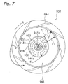
- a hub cover 946 is fixed unrotatably relative to a hub 943 so that it covers a cooling air hole 943a of the hub 943 from the lower side as shown in FIG. 6 and FIG. 7.
- the hub 943 has a plurality (three in the present embodiment) of positioning holes 943b formed between cooling air holes 943a and a rotary shaft 941a in the radial direction, and screw holes 943c provided between the positioning holes 943b in the circumferential direction.
- the hub cover 946 has a positioning pin 946a that protrudes toward the side of the fan motor provided opposing the positioning hole 943a, and a screw hole 946b, wherein a screw 953 provided so that it opposes the screw hole 943c is inserted. Thereby, the hub cover 946 is fixed so that it rotates integrated with the hub 943.
- the hub cover 946 is arranged spaced apart from the surface formed by the cooling air holes 943a of the hub 943, and the outer peripheral part thereof is open toward a main air passageway 910. Furthermore, the hub cover 946 has a plurality of guide blades 952 provided between the cooling air holes 943a in the circumferential direction and that are provided so that they protrude radially.
- the fan motor cooling mechanism 951 of the centrifugal fan 904 includes the cooling air holes 943a of the hub 943, and guide blades 952 of the hub cover 946.
- the air that is sucked in from the air inlet along the rotary shaft 941a direction flows in the arrow C direction shown in FIG. 6, the same as in the present embodiment.
- the revolving direction velocity which has a velocity vector F 3 (a velocity vector that combines the velocity vector F 2 and the velocity vector F 1 corresponding to the rotational velocity of the hub 943), unfortunately grows larger than the revolving direction velocity having a velocity vector F 3 of the air flow blown out from the cooling air holes 943a in the motor cooling mechanism 951 of the present embodiment.
- the fan motor cooling mechanism 51 of the centrifugal fan 4 can guide the flow of air (arrow F) blown out from the cooling air holes 43a to the side of the hub 43 opposite the fan motor so that the revolving direction velocity of the flow decreases.
- any increase in the noise level of the centrifugal fan 4 generated when the flow of air blown out from the cooling air holes 43a to the side of the hub 43 opposite the fan motor merges with the flow of air that flows through the main air passageway 10, is suppressed; furthermore, any increase in the noise level of the air conditioner 1 is also suppressed.
- the present invention can reduce the noise level by approximately 1 dB, while obtaining a prescribed air volume and fan motor cooling performance.
- the air guide 52 is formed integrated with the hub 43 in the present embodiment, it is possible to reduce the number of parts constituting the turbo impeller 42.
- a fan motor cooling mechanism 151 of a centrifugal fan 104 built into an air conditioner 101 of the present embodiment has, as shown in FIG. 8 through FIG. 10, cooling air holes 143a formed in the hub 143 of the centrifugal fan 104, and an air guide 152 provided corresponding to the cooling air holes 143a.
- the cooling air hole 143a is a hole provided in the hub 143 for guiding to the vicinity of the fan motor a portion of the air blown out toward the outer peripheral side by the turbo impeller 142, the same as in the first embodiment.
- the cooling air hole 143a is a long hole and a plurality thereof (five holes in the present embodiment) are formed arrayed concentrically with the hub 143.
- the air guide 152 is a half-pipe shaped part provided so that it covers each of the cooling air holes 143a from the upper surface side of the hub 143 (the fan motor side), and an opening is formed in the R direction side thereof.
- the air that flows from the upper surface side of the cooling air holes 143a (fan motor side) to the lower surface side of the hub 143 can be guided so that it blows out toward the counter R direction (refer to the arrow F in FIG. 10), and any increase in the noise level can be suppressed, the same as in the first embodiment.
- the air guides 52, 152 of the fan motor cooling mechanisms 51, 151 were formed integrated with the hub 43, 143; however, they may also be provided in the hub cover, the same as the motor cooling mechanism 951 in the conventional example.
- a fan motor cooling mechanism 251 of a centrifugal fan 204 built into an air conditioner 201 of the present embodiment includes, as shown in FIG. 11 and FIG. 12, cooling air holes 243a formed in a hub 243, and a volute blade-shaped guide blade 252 (air guide) provided in a hub cover 246.
- the hub cover 246 is fixed so that it rotates integrated with the hub 243 using a screw and a positioning pin, the same as the hub cover 946 in the conventional example.
- the guide blade 252 is a plurality (two in the present embodiment) of volute blades that are inclined rearward with respect to the rotational direction (R direction) of the hub 243.
- the present embodiment can guide the air that flows from the upper surface side of the cooling air holes 243a (fan motor side) toward the lower surface side of the hub 243, so that it blows out toward the counter R direction.
- the air flow consequently forms a flow having a velocity vector F 3 that combines the velocity vector F 2 and the velocity vector F 1 that corresponds to the rotational velocity of the hub 243, and is blown out on the main air passageway 210 side.
- the guide blade 252 functions to cancel out the revolving direction velocity in the R direction that the air flow (arrow F) returning from the cooling air holes 243a to the main air passageway 210 has when it flows into the guide blade 252, and any increase in the level of noise is consequently suppressed, the same as in the first and second embodiments.
- the present embodiment obtains a turbo impeller 242 capable of suppressing any increase in the noise level by just changing the shape of the guide blade provided in the hub cover 246 from the conventional guide blade 952 to the guide blade 252, without changing the structure of the hub 943 of the turbo impeller 942 in the conventional example.
- the guide blade 252 in the third embodiment was volute blade-shaped, but may also be another shape, such as a turbo blade.
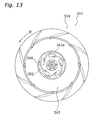
- a fan motor cooling mechanism 351 of a centrifugal fan 304 built into an air conditioner 301 of the present embodiment includes, as shown in FIG. 13, cooling air holes 343a formed in a hub 343, and a turbo blade-shaped guide blade 352 (air guide) provided in a hub cover 346.
- the guide blade 352 is a plurality of turbo blades (five in the present embodiment) that are inclined rearward with respect to the rotational direction (R direction) of the hub 343. Thereby, the air flowing from the upper surface side (fan motor side) of the cooling air holes 343a toward the lower surface side of the hub 343 can be guided so that it blows out toward the counter R direction, obtaining an effect the same as the third embodiment.
- the air guides 252, 352 were formed in the hub covers 246, 346; however, they may also be formed in the hubs 243, 343.
- a fan motor cooling mechanism 451 of a centrifugal fan 404 built into an air conditioner 401 of the present embodiment includes, as shown in FIG. 14 and FIG. 15, cooling air holes 443a formed in a hub 443, and a turbo blade-shaped guide blade 452 (air guide) provided in a hub cover 446, the same as in the fourth embodiment.
- the present embodiment provided an illustrative example for the case in which a turbo blade-shaped guide blade 452 (air guide) is provided in the hub 446; however, the present embodiment is not limited thereto, and a volute blade-shaped guide blade may be provided in the hub, the same as in the third embodiment.
- the use of the present invention obtains a prescribed cooling effect in a fan motor and enables the suppression of any increase in the noise level in a centrifugal fan that sucks in air from the rotary shaft direction and blows out air in a direction that intersects the rotary shaft, and in an air conditioner provided therewith.
Landscapes
- Engineering & Computer Science (AREA)
- Mechanical Engineering (AREA)
- General Engineering & Computer Science (AREA)
- Chemical & Material Sciences (AREA)
- Combustion & Propulsion (AREA)
- Physics & Mathematics (AREA)
- Thermal Sciences (AREA)
- Structures Of Non-Positive Displacement Pumps (AREA)
- Air-Conditioning Room Units, And Self-Contained Units In General (AREA)
Abstract
Description
Claims (8)
- A centrifugal fan (4, 104, 204, 304, 404) that sucks in air from a rotary shaft direction and blows air out in a direction that intersects a rotary shaft (41a), comprising:an electric motor (41) having said rotary shaft;a main plate (43, 143, 243, 343, 443) having a cooling air hole (43a, 143a, 243a, 343a, 443a) and being coupled to and rotationally driven by said rotary shaft;a plurality of blades (44) provided on the surface of said main plate on the side opposite an electric motor and at a position on the outer peripheral side of the radial position of said cooling air hole; andan air guide (52, 152, 252, 352, 452) that, after a portion of the blown out air has been guided to the vicinity of said electric motor and has cooled said electric motor, guides the air flow so that the revolving direction velocity decreases when blown out from said cooling air hole to the side of said main plate opposite said electric motor.
- A centrifugal fan (4, 104, 204, 304, 404) that sucks in air from a rotary shaft direction and blows air out in a direction that intersects a rotary shaft (41a), comprising:an electric motor (41) having said rotary shaft;a main plate (43, 143, 243, 343, 443) having a cooling air hole (43a, 143a, 243a, 343a, 443a) and being coupled to and rotationally driven by said rotary shaft;a plurality of blades (44) provided on the surface of said main plate on the side opposite an electric motor and at a position on the outer peripheral side of the radial position of said cooling air hole; andan air guide (52, 152, 252, 352, 452) that, after a portion of the blown out air has been guided to the vicinity of said electric motor and has cooled said electric motor, guides the air flow so that it is blown out toward the side of the main plate in the counter rotational direction when blown out from said cooling air hole to the side of said main plate opposite said electric motor.
- The centrifugal fan (4, 104) as recited in Claim 1 or Claim 2, wherein
said air guide (52, 152) is formed integrated with said main plate (43, 143). - The centrifugal fan (204, 304, 404) as recited in Claim 2, further comprising:wherein,a cover (246, 346, 446) that covers said cooling air hole (243a, 343a, 443a) from the side opposite the electric motor, and that is provided so that it rotates integrally with said main plate (243, 343, 443);
said air guide (252, 352, 452) is formed between said cover and said main plate. - The centrifugal fan (204, 304, 404) as recited in Claim 4, wherein
said air guide (252, 352, 452) has a blade shape inclined rearwards in the rotational direction of said cover (246, 346, 446). - The centrifugal fan (204) as recited in Claim 5, wherein
said air guide (252) has a volute blade shape. - The centrifugal fan (204, 304) as recited in any one claim of Claim 4 through Claim 6
wherein
said air guide (252, 352) is formed in said cover (246, 346). - An air conditioner (1, 101, 201, 301, 401), comprising:the centrifugal fan (4, 104, 204, 304, 404) as recited in any one claim of Claim 1 through Claim 7;a heat exchanger (6) arranged on the outer peripheral side of said centrifugal fan; anda casing (2) that houses said centrifugal fan and said heat exchanger.
Applications Claiming Priority (3)
| Application Number | Priority Date | Filing Date | Title |
|---|---|---|---|
| JP2002363488 | 2002-12-16 | ||
| JP2002363488 | 2002-12-16 | ||
| PCT/JP2003/014860 WO2004055380A1 (en) | 2002-12-16 | 2003-11-20 | Centrifugal blower and air conditioner with the same |
Publications (2)
| Publication Number | Publication Date |
|---|---|
| EP1574718A1 true EP1574718A1 (en) | 2005-09-14 |
| EP1574718A4 EP1574718A4 (en) | 2011-01-26 |
Family
ID=32588208
Family Applications (1)
| Application Number | Title | Priority Date | Filing Date |
|---|---|---|---|
| EP03774113A Withdrawn EP1574718A4 (en) | 2002-12-16 | 2003-11-20 | CENTRIFUGAL BLOWER AND AIR CONDITIONER HAVING THE SAME |
Country Status (7)
| Country | Link |
|---|---|
| US (1) | US7614250B2 (en) |
| EP (1) | EP1574718A4 (en) |
| JP (1) | JPWO2004055380A1 (en) |
| KR (1) | KR20040101528A (en) |
| CN (2) | CN100379998C (en) |
| AU (1) | AU2003284610B2 (en) |
| WO (1) | WO2004055380A1 (en) |
Cited By (2)
| Publication number | Priority date | Publication date | Assignee | Title |
|---|---|---|---|---|
| WO2015026558A1 (en) * | 2013-08-22 | 2015-02-26 | Stanley Black & Decker, Inc. | Hydraulic power unit |
| EP2808550A4 (en) * | 2012-01-23 | 2015-10-28 | Mitsubishi Heavy Ind Ltd | CENTRIFUGAL MACHINE FOR FLUID |
Families Citing this family (55)
| Publication number | Priority date | Publication date | Assignee | Title |
|---|---|---|---|---|
| US7616440B2 (en) * | 2004-04-19 | 2009-11-10 | Hewlett-Packard Development Company, L.P. | Fan unit and methods of forming same |
| CN100432449C (en) * | 2005-01-19 | 2008-11-12 | 乐金电子(天津)电器有限公司 | Impeller cover of centrifugal fan |
| JP4684085B2 (en) * | 2005-02-24 | 2011-05-18 | 三菱電機株式会社 | Embedded ceiling air conditioner |
| JP4525535B2 (en) * | 2005-09-05 | 2010-08-18 | パナソニック株式会社 | Induction heating cooker |
| KR100758905B1 (en) * | 2005-12-26 | 2007-09-17 | 엘지전자 주식회사 | Indoor unit of air conditioner |
| KR100789820B1 (en) * | 2005-12-26 | 2008-01-02 | 엘지전자 주식회사 | Indoor unit of air conditioner |
| NZ577485A (en) | 2006-05-24 | 2011-01-28 | Resmed Ltd | Compact low noise efficient blower for CPAP devices with a shield to prevent a line-of-sight path within |
| EP1908872A1 (en) * | 2006-10-02 | 2008-04-09 | Falmer Investments Limited | Blower for a textiles processing machine |
| JP4877777B2 (en) * | 2006-11-01 | 2012-02-15 | 株式会社日立産機システム | Blower |
| GB2459063B (en) * | 2007-03-14 | 2012-06-06 | Mitsubishi Electric Corp | Air conditioner |
| CN101498320B (en) * | 2008-02-01 | 2012-04-25 | 台达电子工业股份有限公司 | Fan and impeller thereof |
| TWI354530B (en) * | 2008-02-01 | 2011-12-11 | Delta Electronics Inc | Fan and impeller thereof |
| EP2113726A1 (en) * | 2008-04-28 | 2009-11-04 | Hans Östberg | A ventilating arrangement |
| JP2010196694A (en) * | 2009-01-30 | 2010-09-09 | Sanyo Electric Co Ltd | Centrifugal blower and air conditioning device |
| JP5359458B2 (en) * | 2009-03-27 | 2013-12-04 | ダイキン工業株式会社 | Air conditioner, casing, and decorative panel |
| FR2947040B1 (en) * | 2009-06-23 | 2014-01-03 | Cinier Radiateurs | REVERSIBLE RADIATOR |
| UA107094C2 (en) | 2009-11-03 | 2014-11-25 | CENTRAL CEILING FAN | |
| JP2011174385A (en) * | 2010-02-23 | 2011-09-08 | Nippon Densan Corp | Impeller and centrifugal fan |
| US8935926B2 (en) * | 2010-10-28 | 2015-01-20 | United Technologies Corporation | Centrifugal compressor with bleed flow splitter for a gas turbine engine |
| US9121414B2 (en) * | 2010-11-05 | 2015-09-01 | Gentherm Incorporated | Low-profile blowers and methods |
| EP2698543B1 (en) * | 2011-04-12 | 2017-10-11 | Mitsubishi Electric Corporation | Centrifugal fan and air conditioner |
| KR20140108389A (en) * | 2013-02-26 | 2014-09-11 | 현대중공업 주식회사 | Centrifugal pump having balancing holes |
| JP6142285B2 (en) * | 2013-03-21 | 2017-06-07 | パナソニックIpマネジメント株式会社 | Single suction centrifugal blower |
| KR102199376B1 (en) * | 2013-07-12 | 2021-01-06 | 엘지전자 주식회사 | Centrifugal blower and air conditioner using the same |
| JP6244547B2 (en) * | 2013-09-24 | 2017-12-13 | パナソニックIpマネジメント株式会社 | Single suction centrifugal blower |
| US9995305B2 (en) * | 2013-10-08 | 2018-06-12 | Regal Beloit America, Inc. | Fluid flow apparatus, fan assembly and associated method |
| US20150104159A1 (en) * | 2013-10-16 | 2015-04-16 | Restless Noggins Design, Llc | Heating and cooling apparatus |
| DE102013222207B4 (en) * | 2013-10-31 | 2022-03-03 | Mahle International Gmbh | centrifugal fan |
| US9765788B2 (en) * | 2013-12-04 | 2017-09-19 | Apple Inc. | Shrouded fan impeller with reduced cover overlap |
| JP6211101B2 (en) * | 2014-01-10 | 2017-10-11 | 三菱電機株式会社 | Centrifugal fan, air conditioner and air purifier |
| JP6303654B2 (en) * | 2014-03-14 | 2018-04-04 | 株式会社デンソー | Centrifugal multiblade blower |
| CN104279188B (en) * | 2014-10-29 | 2017-08-01 | 珠海格力电器股份有限公司 | Centrifugal fan and air conditioner with same |
| DE102015101938A1 (en) * | 2015-02-11 | 2016-08-11 | Ebm-Papst Mulfingen Gmbh & Co. Kg | Fan wheel and fan |
| CN106286334A (en) * | 2015-05-27 | 2017-01-04 | 江苏图博可特曙光涂层有限公司 | A kind of tubing temperature-dropping fan |
| JP6620427B2 (en) * | 2015-05-28 | 2019-12-18 | ダイキン工業株式会社 | Blower |
| CN105134652A (en) * | 2015-10-09 | 2015-12-09 | 珠海格力电器股份有限公司 | Impeller assembly, air conditioner, range hood and vibration reduction method of impeller assembly |
| CN105240315A (en) * | 2015-11-20 | 2016-01-13 | 苏州市金翔钛设备有限公司 | Fan impeller convenient for clearing dust |
| WO2017208657A1 (en) * | 2016-05-30 | 2017-12-07 | 株式会社デンソー | Blower unit and method for manufacturing blower unit |
| CN106122086B (en) * | 2016-08-30 | 2019-04-19 | 芜湖美智空调设备有限公司 | Centrifugal impellers and air conditioners |
| DE102016012801A1 (en) * | 2016-10-26 | 2018-04-26 | Man Truck & Bus Ag | axial fan |
| JP6755786B2 (en) * | 2016-12-05 | 2020-09-16 | 日本電産コパル電子株式会社 | Blower and a blower system with the blower |
| EP3556584B1 (en) * | 2016-12-14 | 2020-09-30 | Denso Corporation | Air conditioner |
| JP6635077B2 (en) * | 2017-03-13 | 2020-01-22 | 株式会社デンソー | Centrifugal blower |
| JP6747402B2 (en) * | 2017-08-11 | 2020-08-26 | 株式会社デンソー | Blower |
| JP6985850B2 (en) * | 2017-08-21 | 2021-12-22 | リンナイ株式会社 | Centrifugal fan |
| CN107906616B (en) * | 2017-12-22 | 2023-09-26 | 海信科龙电器股份有限公司 | Shroud for fan motor in wall-mounted air conditioner indoor unit |
| JP7278710B2 (en) * | 2018-01-30 | 2023-05-22 | 三菱重工サーマルシステムズ株式会社 | Ceiling-mounted air conditioner |
| CN109236735A (en) * | 2018-10-19 | 2019-01-18 | 宁波奥克斯电气股份有限公司 | A kind of centrifugal wind wheel and ceiling machine |
| JP7070361B2 (en) * | 2018-11-19 | 2022-05-18 | 株式会社デンソー | Blower |
| CN109538531A (en) * | 2019-01-03 | 2019-03-29 | 格力电器(合肥)有限公司 | Centrifugal fan blade assembly, centrifugal fan and air conditioning unit |
| JP7302505B2 (en) * | 2020-02-27 | 2023-07-04 | 株式会社デンソー | blower |
| US12270412B2 (en) | 2021-10-06 | 2025-04-08 | Regal Beloit America, Inc. | Blower having a protrusion adjacent the static tap hole |
| GB2627101B (en) | 2022-01-17 | 2026-01-21 | Mitsubishi Electric Corp | Centrifugal blower, and indoor unit |
| CN115930298B (en) * | 2022-05-23 | 2026-05-12 | 天津万和晨业能源科技有限公司 | Air conditioning device |
| CN116241501B (en) * | 2023-02-10 | 2026-05-15 | 广东顺威精密塑料股份有限公司 | Filter shroud with pressurization function, centrifugal impeller and centrifugal fan |
Family Cites Families (19)
| Publication number | Priority date | Publication date | Assignee | Title |
|---|---|---|---|---|
| JPS54168607U (en) | 1978-05-19 | 1979-11-28 | ||
| SE443408B (en) | 1979-09-28 | 1986-02-24 | Sueddeutsche Kuehler Behr | RADIAL SPLIT FOR HEATING OR AIR CONDITIONING INSTALLATIONS IN VEHICLES |
| JPS56150888U (en) | 1980-04-11 | 1981-11-12 | ||
| JPS60164699U (en) | 1984-04-09 | 1985-11-01 | 日産自動車株式会社 | centrifugal blower |
| JPH0676689A (en) | 1992-08-31 | 1994-03-18 | Fujitsu Ten Ltd | Reset switch |
| JP3270567B2 (en) | 1993-04-12 | 2002-04-02 | 松下冷機株式会社 | Blower |
| JP3641088B2 (en) | 1996-11-22 | 2005-04-20 | ダイキン工業株式会社 | Turbo fan |
| JPH11101194A (en) | 1997-09-30 | 1999-04-13 | Daikin Ind Ltd | Centrifugal blower and air conditioner provided with the centrifugal blower |
| JP3882324B2 (en) | 1998-03-24 | 2007-02-14 | ダイキン工業株式会社 | Centrifugal fan |
| JP3758396B2 (en) * | 1999-01-11 | 2006-03-22 | 三菱電機株式会社 | Air conditioner |
| JP2000227231A (en) * | 1999-02-05 | 2000-08-15 | Fujitsu General Ltd | Ceiling-mounted air conditioner |
| JP2001295788A (en) * | 2000-04-14 | 2001-10-26 | Daikin Ind Ltd | Fan motor integrated blower |
| CN2420560Y (en) * | 2000-04-24 | 2001-02-21 | 大金工业株式会社 | Centrafugal air blower and air conditioner equipment with said centrafugal air blower |
| CN2431523Y (en) | 2000-04-26 | 2001-05-23 | 大金工业株式会社 | Centrifugal blower |
| US6669902B1 (en) * | 2000-11-08 | 2003-12-30 | L'air Liquide - Societe Anonyme A'directoire Et Conseil De Surveillance Pour L'etude Et L'exploitation Des Procedes Georges Claude | Ozonated foam medium and production system and method for sanitizing a food processing environment |
| US6551641B1 (en) * | 2000-11-13 | 2003-04-22 | Global Food Technologies, Inc. | Fish, poultry, meat processing method |
| JP2002227231A (en) * | 2001-02-01 | 2002-08-14 | Hitachi Constr Mach Co Ltd | Ground improvement attachment and ground improvement equipment for excavator type excavator |
| US6514052B2 (en) * | 2001-03-30 | 2003-02-04 | Emerson Electric Co. | Two sided radial fan for motor cooling |
| KR20040104772A (en) * | 2003-06-03 | 2004-12-13 | 삼성전자주식회사 | Turbofan and air conditioner with the same |
-
2003
- 2003-11-20 KR KR10-2004-7016736A patent/KR20040101528A/en not_active Ceased
- 2003-11-20 EP EP03774113A patent/EP1574718A4/en not_active Withdrawn
- 2003-11-20 US US10/507,019 patent/US7614250B2/en not_active Expired - Fee Related
- 2003-11-20 AU AU2003284610A patent/AU2003284610B2/en not_active Ceased
- 2003-11-20 WO PCT/JP2003/014860 patent/WO2004055380A1/en not_active Ceased
- 2003-11-20 JP JP2004560599A patent/JPWO2004055380A1/en active Pending
- 2003-12-15 CN CNB2003101233710A patent/CN100379998C/en not_active Expired - Lifetime
- 2003-12-15 CN CNU2003201237859U patent/CN2762000Y/en not_active Expired - Fee Related
Cited By (3)
| Publication number | Priority date | Publication date | Assignee | Title |
|---|---|---|---|---|
| EP2808550A4 (en) * | 2012-01-23 | 2015-10-28 | Mitsubishi Heavy Ind Ltd | CENTRIFUGAL MACHINE FOR FLUID |
| US9556876B2 (en) | 2012-01-23 | 2017-01-31 | Mitsubishi Heavy Industries, Ltd. | Centrifugal fluid machine |
| WO2015026558A1 (en) * | 2013-08-22 | 2015-02-26 | Stanley Black & Decker, Inc. | Hydraulic power unit |
Also Published As
| Publication number | Publication date |
|---|---|
| WO2004055380A1 (en) | 2004-07-01 |
| AU2003284610A1 (en) | 2004-07-09 |
| CN2762000Y (en) | 2006-03-01 |
| US7614250B2 (en) | 2009-11-10 |
| AU2003284610B2 (en) | 2006-11-16 |
| CN100379998C (en) | 2008-04-09 |
| KR20040101528A (en) | 2004-12-02 |
| CN1508440A (en) | 2004-06-30 |
| US20050103042A1 (en) | 2005-05-19 |
| JPWO2004055380A1 (en) | 2006-04-20 |
| EP1574718A4 (en) | 2011-01-26 |
Similar Documents
| Publication | Publication Date | Title |
|---|---|---|
| US7614250B2 (en) | Centrifugal fan with air guide | |
| US7191613B2 (en) | Turbo fan and air conditioner having the same applied thereto | |
| KR102076668B1 (en) | An indoor unit for an air conditioner | |
| EP1878923B1 (en) | Impeller of centrifugal fan and centrifugal fan disposed with the impeller | |
| CN109882932B (en) | Air conditioner indoor unit and air conditioner | |
| JP3758396B2 (en) | Air conditioner | |
| US11639084B2 (en) | Blower unit of air conditioner for vehicle | |
| JP2004353510A (en) | Centrifugal blower and air conditioner equipped with centrifugal blower | |
| JP2004068644A (en) | Centrifugal blower | |
| US6298682B1 (en) | Condensate deflector for an air conditioner | |
| JP3614649B2 (en) | Embedded ceiling air conditioner | |
| JP2018001820A (en) | Blower unit | |
| JP5076324B2 (en) | Centrifugal fan | |
| JPH0996425A (en) | Air conditioner outdoor unit | |
| JP3812467B2 (en) | Centrifugal blower impeller and centrifugal blower using the impeller | |
| KR0161074B1 (en) | Air conditioner | |
| CN117287753B (en) | Air supply assembly and air conditioner | |
| KR102698344B1 (en) | Blower unit of two layer type air conditioner for vehicle | |
| KR100377749B1 (en) | Thru the wall type air conditioner | |
| KR100364765B1 (en) | air conditioner | |
| WO2005040686A2 (en) | Window type air conditioner | |
| KR101419943B1 (en) | Air conditioner and Fan assembly thereof | |
| JPH04132337U (en) | Outdoor unit of air conditioner | |
| KR20020009139A (en) | Ventilation apparatus for air-conditioner | |
| JP2005127177A (en) | Turbo fan |
Legal Events
| Date | Code | Title | Description |
|---|---|---|---|
| PUAI | Public reference made under article 153(3) epc to a published international application that has entered the european phase |
Free format text: ORIGINAL CODE: 0009012 |
|
| 17P | Request for examination filed |
Effective date: 20041109 |
|
| AK | Designated contracting states |
Kind code of ref document: A1 Designated state(s): AT BE BG CH CY CZ DE DK EE ES FI FR GB GR HU IE IT LI LU MC NL PT RO SE SI SK TR |
|
| AX | Request for extension of the european patent |
Extension state: AL LT LV MK |
|
| DAX | Request for extension of the european patent (deleted) | ||
| A4 | Supplementary search report drawn up and despatched |
Effective date: 20101223 |
|
| 17Q | First examination report despatched |
Effective date: 20110504 |
|
| GRAP | Despatch of communication of intention to grant a patent |
Free format text: ORIGINAL CODE: EPIDOSNIGR1 |
|
| INTG | Intention to grant announced |
Effective date: 20170922 |
|
| STAA | Information on the status of an ep patent application or granted ep patent |
Free format text: STATUS: THE APPLICATION IS DEEMED TO BE WITHDRAWN |
|
| 18D | Application deemed to be withdrawn |
Effective date: 20180203 |
|
| RIC1 | Information provided on ipc code assigned before grant |
Ipc: F04D 29/28 20060101ALI20040706BHEP Ipc: F04D 29/58 20060101AFI20040706BHEP |