EP1574695A2 - A control apparatus for controlling a plant by using a delta-sigma modulation algorithm - Google Patents
A control apparatus for controlling a plant by using a delta-sigma modulation algorithm Download PDFInfo
- Publication number
- EP1574695A2 EP1574695A2 EP05001449A EP05001449A EP1574695A2 EP 1574695 A2 EP1574695 A2 EP 1574695A2 EP 05001449 A EP05001449 A EP 05001449A EP 05001449 A EP05001449 A EP 05001449A EP 1574695 A2 EP1574695 A2 EP 1574695A2
- Authority
- EP
- European Patent Office
- Prior art keywords
- modulated signal
- manipulated variable
- controlled object
- adaptive offset
- value
- Prior art date
- Legal status (The legal status is an assumption and is not a legal conclusion. Google has not performed a legal analysis and makes no representation as to the accuracy of the status listed.)
- Withdrawn
Links
Images


Classifications
-
- F—MECHANICAL ENGINEERING; LIGHTING; HEATING; WEAPONS; BLASTING
- F02—COMBUSTION ENGINES; HOT-GAS OR COMBUSTION-PRODUCT ENGINE PLANTS
- F02D—CONTROLLING COMBUSTION ENGINES
- F02D41/00—Electrical control of supply of combustible mixture or its constituents
- F02D41/02—Circuit arrangements for generating control signals
- F02D41/14—Introducing closed-loop corrections
- F02D41/1401—Introducing closed-loop corrections characterised by the control or regulation method
-
- F—MECHANICAL ENGINEERING; LIGHTING; HEATING; WEAPONS; BLASTING
- F01—MACHINES OR ENGINES IN GENERAL; ENGINE PLANTS IN GENERAL; STEAM ENGINES
- F01L—CYCLICALLY OPERATING VALVES FOR MACHINES OR ENGINES
- F01L1/00—Valve-gear or valve arrangements, e.g. lift-valve gear
- F01L1/34—Valve-gear or valve arrangements, e.g. lift-valve gear characterised by the provision of means for changing the timing of the valves without changing the duration of opening and without affecting the magnitude of the valve lift
- F01L1/344—Valve-gear or valve arrangements, e.g. lift-valve gear characterised by the provision of means for changing the timing of the valves without changing the duration of opening and without affecting the magnitude of the valve lift changing the angular relationship between crankshaft and camshaft, e.g. using helicoidal gear
- F01L1/3442—Valve-gear or valve arrangements, e.g. lift-valve gear characterised by the provision of means for changing the timing of the valves without changing the duration of opening and without affecting the magnitude of the valve lift changing the angular relationship between crankshaft and camshaft, e.g. using helicoidal gear using hydraulic chambers with variable volume to transmit the rotating force
-
- F—MECHANICAL ENGINEERING; LIGHTING; HEATING; WEAPONS; BLASTING
- F02—COMBUSTION ENGINES; HOT-GAS OR COMBUSTION-PRODUCT ENGINE PLANTS
- F02D—CONTROLLING COMBUSTION ENGINES
- F02D41/00—Electrical control of supply of combustible mixture or its constituents
- F02D41/02—Circuit arrangements for generating control signals
- F02D41/14—Introducing closed-loop corrections
- F02D41/1401—Introducing closed-loop corrections characterised by the control or regulation method
- F02D41/1403—Sliding mode control
-
- F—MECHANICAL ENGINEERING; LIGHTING; HEATING; WEAPONS; BLASTING
- F01—MACHINES OR ENGINES IN GENERAL; ENGINE PLANTS IN GENERAL; STEAM ENGINES
- F01L—CYCLICALLY OPERATING VALVES FOR MACHINES OR ENGINES
- F01L1/00—Valve-gear or valve arrangements, e.g. lift-valve gear
- F01L1/34—Valve-gear or valve arrangements, e.g. lift-valve gear characterised by the provision of means for changing the timing of the valves without changing the duration of opening and without affecting the magnitude of the valve lift
- F01L1/344—Valve-gear or valve arrangements, e.g. lift-valve gear characterised by the provision of means for changing the timing of the valves without changing the duration of opening and without affecting the magnitude of the valve lift changing the angular relationship between crankshaft and camshaft, e.g. using helicoidal gear
- F01L1/3442—Valve-gear or valve arrangements, e.g. lift-valve gear characterised by the provision of means for changing the timing of the valves without changing the duration of opening and without affecting the magnitude of the valve lift changing the angular relationship between crankshaft and camshaft, e.g. using helicoidal gear using hydraulic chambers with variable volume to transmit the rotating force
- F01L2001/34423—Details relating to the hydraulic feeding circuit
- F01L2001/34426—Oil control valves
- F01L2001/3443—Solenoid driven oil control valves
-
- F—MECHANICAL ENGINEERING; LIGHTING; HEATING; WEAPONS; BLASTING
- F01—MACHINES OR ENGINES IN GENERAL; ENGINE PLANTS IN GENERAL; STEAM ENGINES
- F01L—CYCLICALLY OPERATING VALVES FOR MACHINES OR ENGINES
- F01L2800/00—Methods of operation using a variable valve timing mechanism
- F01L2800/05—Timing control under consideration of oil condition
-
- F—MECHANICAL ENGINEERING; LIGHTING; HEATING; WEAPONS; BLASTING
- F02—COMBUSTION ENGINES; HOT-GAS OR COMBUSTION-PRODUCT ENGINE PLANTS
- F02D—CONTROLLING COMBUSTION ENGINES
- F02D13/00—Controlling the engine output power by varying inlet or exhaust valve operating characteristics, e.g. timing
- F02D13/02—Controlling the engine output power by varying inlet or exhaust valve operating characteristics, e.g. timing during engine operation
- F02D13/0203—Variable control of intake and exhaust valves
- F02D13/0207—Variable control of intake and exhaust valves changing valve lift or valve lift and timing
-
- F—MECHANICAL ENGINEERING; LIGHTING; HEATING; WEAPONS; BLASTING
- F02—COMBUSTION ENGINES; HOT-GAS OR COMBUSTION-PRODUCT ENGINE PLANTS
- F02D—CONTROLLING COMBUSTION ENGINES
- F02D41/00—Electrical control of supply of combustible mixture or its constituents
- F02D41/0002—Controlling intake air
- F02D2041/001—Controlling intake air for engines with variable valve actuation
-
- F—MECHANICAL ENGINEERING; LIGHTING; HEATING; WEAPONS; BLASTING
- F02—COMBUSTION ENGINES; HOT-GAS OR COMBUSTION-PRODUCT ENGINE PLANTS
- F02D—CONTROLLING COMBUSTION ENGINES
- F02D35/00—Controlling engines, dependent on conditions exterior or interior to engines, not otherwise provided for
- F02D35/0007—Controlling engines, dependent on conditions exterior or interior to engines, not otherwise provided for using electrical feedback
-
- F—MECHANICAL ENGINEERING; LIGHTING; HEATING; WEAPONS; BLASTING
- F02—COMBUSTION ENGINES; HOT-GAS OR COMBUSTION-PRODUCT ENGINE PLANTS
- F02D—CONTROLLING COMBUSTION ENGINES
- F02D41/00—Electrical control of supply of combustible mixture or its constituents
- F02D41/0002—Controlling intake air
-
- Y—GENERAL TAGGING OF NEW TECHNOLOGICAL DEVELOPMENTS; GENERAL TAGGING OF CROSS-SECTIONAL TECHNOLOGIES SPANNING OVER SEVERAL SECTIONS OF THE IPC; TECHNICAL SUBJECTS COVERED BY FORMER USPC CROSS-REFERENCE ART COLLECTIONS [XRACs] AND DIGESTS
- Y10—TECHNICAL SUBJECTS COVERED BY FORMER USPC
- Y10T—TECHNICAL SUBJECTS COVERED BY FORMER US CLASSIFICATION
- Y10T137/00—Fluid handling
- Y10T137/2278—Pressure modulating relays or followers
Definitions
- the present invention relates to a control apparatus for accurately controlling a plant by using a delta-sigma ( ⁇ ) modulation algorithm.
- a method for controlling a plant (controlled object) by using a delta-sigma modulation algorithm (or a sigma-delta ( ⁇ ) modulation algorithm or a delta ( ⁇ ) modulation algorithm) is known, as shown in the Japanese Patent Publication No. 2003-195908.
- a delta-sigma modulation algorithm or a sigma-delta ( ⁇ ) modulation algorithm or a delta ( ⁇ ) modulation algorithm
- the plant can be accurately controlled by the delta-sigma modulation algorithm.
- FIG 15 is a block diagram showing an example of a control scheme using a delta-sigma modulation algorithm.
- a controller 101 calculates a manipulated variable for causing a controlled variable of a plant to converge to a desired value.
- a modulator 102 uses the delta-sigma modulation algorithm to modulate the manipulated variable.
- the modulated manipulated variable is input into the plant 103.
- An output from the plant 103, which is the controlled variable, is fed back to the controller 101.
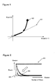
- Figure 16 shows exemplary behaviors of various signals in accordance with a control scheme using a conventional delta-sigma modulation algorithm.
- Rcain indicates the manipulated variable calculated by the controller 101.
- Vcain indicates the modulated manipulated variable, which is a modulated signal generated by the modulator 102.
- CAIN indicates an output from the plant 103, which is a controlled variable.
- CAIN_cmd indicates a desired value of the controlled variable.
- the modulated signal Vcain is generated to switch between +d and -d with respect to a predetermined center value.
- the amplitude of the modulated signal Vcain is 2d.
- the delta-sigma modulation algorithm is capable of reconstructing the manipulated variable Rcain as the modulated signal Vcain.
- an appropriate modulated signal Vcain is generated because the magnitude of the manipulated variable Rcain is smaller than the amplitude 2d of the modulated signal.
- the controlled variable CAIN can be appropriately controlled to follow the desired value CAIN_cmd by applying the modulated signal Vcain to the plant.
- the manipulated variable Rcain exceeds the amplitude 2d of the modulated signal as shown from time t1, such increased manipulated variable Rcain cannot be appropriately modulated because the amplitude of the modulated signal is limited to 2d. A portion of the manipulated variable exceeding the amplitude 2d is not reflected in the modulated signal Vcain. As a result, the manipulated variable Rcain is substantially limited as shown by a dotted line 105. Since the modulated signal is generated with a portion of the manipulated variable Rcain being lost, a deviation occurs between the controlled variable CAIN and the desired value CAIN_cmd. Thus, from time t1, the plant cannot be appropriately controlled.
- Such condition may occur, for example, in a phase control for a camshaft of an engine of a vehicle.
- that actuator is regarded as a plant. If the torque generated by the actuator decreases due to heat generated by the actuator, or if the friction characteristics of the actuator vary due to variations and age deterioration of the actuator, such condition may occur.
- the amplitude 2d of the modulated signal is established to contain the maximum and minimum values. According to such a method, however, the amplitude of the modulated signal may increase. Such increase of the amplitude may destabilize the output of the plant.
- An electromagnet may be used as the actuator.
- the electric current of the electromagnet decreases as the resistance of the electromagnet increases. This decrease of the electric current reduces the torque generated by the actuator.
- such an electric current control cannot handle changes in the friction characteristics.
- a control apparatus comprises a controller for determining a manipulated variable for manipulating a controlled object to cause an output of the controlled object to converge to a desired value and a modulator for modulating the manipulated variable by using one of a delta-sigma modulation algorithm, a sigma-delta modulation algorithm and a delta modulation algorithm to generate a modulated signal that is to be applied to the controlled object.
- the modulator generates the modulated signal so that a center value of an amplitude of the modulated signal follows a change of the manipulated variable.
- the manipulated variable is not damaged due to the amplitude of the modulated signal because the center value of the amplitude of the modulated signal is changed in accordance with a change in the manipulated variable. Since the modulated signal generated without being damaged is applied to the controlled object, the output of the controlled object can accurately converge to a desired value.
- the amplitude of the modulated signal does not need to be increased so as to contain the maximum value and the minimum value of the manipulated variable. Since the amplitude of the modulated signal can be kept small, it can be suppressed that the output of the controlled object oscillates due to the switching characteristics of the modulated signal.
- the modulator further includes an adaptive offset generator for generating an adaptive offset value based on the manipulated variable.
- the modulator generates the modulated signal so that the adaptive offset value is the center value of the amplitude of the modulated signal.
- the modulated signal can be appropriately generated to adapt to a change of the manipulated variable.
- the adaptive offset generator further includes a filter for filtering the manipulated variable to suppress an abrupt change of the adaptive offset value.
- the adaptive offset generator generates the adaptive offset value based on an output from the filter.
- the center value of the amplitude of the modulated signal which is the adaptive offset value
- the accuracy of causing the output of the controlled object to settle to a desired value may deteriorate.
- "fluctuation" may occur in the output of the controlled object when a desired value for the output of the controlled object becomes constant. Such fluctuation can be suppressed by filtering the manipulated variable.
- the adaptive offset generator further includes a unit for limiting the manipulated variable within a predetermined range and a filter for filtering the limited manipulated variable.
- the predetermined range is determined based on a past value of the adaptive offset value.
- Such limiting process prevents the center value of the amplitude of the modulated signal from abruptly changing even when an impulsive change in the manipulated variable occurs due to disturbance and noise.
- the present invention can be applied to various controlled objects.
- the controlled object is a phase mechanism for changing a phase of a cam of an engine.
- the phase mechanism changes the phase of the cam in accordance with the modulated signal.
- the torque for driving the cam may decrease due to heat generation in the phase mechanism.
- the friction characteristics of the phase mechanism may change due to variations and/or age deterioration.
- the controlled object is a lift mechanism for changing a lift amount of a valve of an engine.
- the lift mechanism changes the lift amount in accordance with the modulated signal.
- the effects similar to those of the phase mechanism can be achieved.
- the controlled object is a system extending from a control mechanism for controlling an air/fuel ratio of an engine to an exhaust gas sensor disposed in an exhaust manifold of the engine.
- the control mechanism changes the air/fuel ratio in accordance with the modulated signal.
- a manipulated variable required for achieving an optimal air/fuel ratio may vary due to difference in the fuel properties, deteriorated condition of the catalyst, operating condition of the engine or the like.
- the control scheme of the present invention since the center value of the amplitude of the modulated signal changes in accordance with a change in the manipulated variable, the output of the exhaust gas sensor can converge to a desired value without generating a steady-state error. As a result, an optimal air/fuel ratio can be achieved. Since the amplitude of the modulated signal can be kept small, the range within which the air/fuel ratio varies can be kept small, which leads to the stability of the torque. Engine surging is decreased and the drivability is improved.
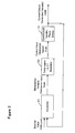
- Figure 1 is a block diagram showing an internal combustion engine (hereinafter referred to as an engine) and a control unit for the engine in accordance with one embodiment of the invention.
- an engine an internal combustion engine
- control unit for the engine in accordance with one embodiment of the invention.
- An electronic control unit (hereinafter referred to as an ECU) 1 is essentially a computer and comprises an input interface 1a for receiving data sent from each part of the vehicle, a CPU 1b for carrying out operations for controlling each part of the vehicle, a memory 1c. including a read only memory (ROM) and a random access memory (RAM), and an output interface 1d for sending control signals to each part of the vehicle.
- Programs and various data for controlling each part of the vehicle are stored in the ROM.
- the ROM may be a rewritable ROM such as an EPROM.
- the RAM provides work areas for operations by the CPU 1b, in which data sent from each part of the vehicle as well as control signals to be sent out to each part of the vehicle are temporarily stored.
- An engine 2 is, for example, a 4-cycle, DOHC gasoline engine.
- the engine 2 comprises an intake camshaft 5 and an exhaust camshaft 6.
- the intake camshaft 5 has an intake cam 5a for driving an intake valve 3 to open and close.
- the exhaust camshaft 6 has an exhaust cam 6a for driving an exhaust valve 4 to open and close.
- These intake and exhaust camshafts 5 and 6 are connected to a crankshaft 7 via a timing belt (not shown). These camshafts rotate once for every two rotations of the crankshaft 7.
- a continuously variable phase device (hereinafter referred to as a "phase device") 10 has a continuously variable phase mechanism (hereinafter referred to as a "phase mechanism") 11 and a hydraulic driving unit 12.
- the hydraulic driving unit 12 drives the phase mechanism 11 with a hydraulic pressure in accordance with a command value supplied by the ECU 1. In doing so, an actual phase CAIN of the intake cam 5a can continuously advance or retard with respect to the crankshaft 7.
- the phase device 10 will be described in detail later referring to Figure 2.
- a cam angle sensor 20 is disposed at an end portion of the intake camshaft 5. As the intake camshaft 5 rotates, the cam angle sensor 20 outputs to the ECU 1 a CAM signal, which is a pulse signal, at every predetermined cam angle (for example, every one degree).
- a throttle valve 16 is disposed in an intake manifold 15 of the engine 2. An opening degree of the throttle valve 16 is controlled by a control signal from the ECU 1.
- An intake manifold pressure (Pb) sensor 18 is disposed downstream of the throttle valve 16. The intake manifold pressure Pb detected by the Pb sensor 18 is sent to the ECU 1.
- a fuel injection valve 19 is provided, for each cylinder, in the intake manifold 15.
- the fuel injection valve 19 is supplied with fuel from a fuel tank (not shown) to inject the fuel in accordance with a control signal from the ECU 1.
- a crank angle sensor 21 is disposed in the engine 2.
- the crank angle sensor 21 outputs a CRK signal and a TDC signal to the ECU 1 in accordance with the rotation of the crankshaft 7.
- the CRK signal is a pulse signal that is output at every predetermined crank angle (for example, 30 degrees).
- the ECU 1 calculates a rotational speed NE of the engine 2 in accordance with the CRK signal.
- the ECU 1 also calculates the phase CAIN based on the CRK signal and the CAM signal.
- the TDC signal is also a pulse signal that is output at a crank angle associated with a TDC position of a piston 9.
- An exhaust manifold 22 is connected on the downstream side of the engine 2.
- the engine 2 emits exhaust gas through the exhaust manifold 22.
- a wide-range air/fuel ratio (LAF) sensor 24 is disposed upstream of the catalytic converter 23.
- the LAF sensor 24 detects an air/fuel ratio over a wide range extending from rich to lean. The detected air/fuel ratio is sent to the ECU 1.
- An 02 (exhaust gas) sensor 25 is disposed downstream of the catalyst converter 23.
- the 02 sensor 25 is a binary-type of exhaust gas concentration sensor.
- the 02 sensor outputs a high level signal when the air/fuel ratio is richer than the stoichiometric air/fuel ratio, and outputs a low level signal when the air/fuel ratio is leaner than the stoichiometric air/fuel ratio.
- the electric signal is sent to the ECU 1.
- Signals sent to the ECU 1 are passed to the input interface 1a.
- the input interface 5a converts analog signal values into digital signal values.
- the CPU 1b processes the resulting digital signals, performs operations in accordance with one or more programs stored in the memory 1c, and creates control signals.
- the output interface 1d sends these control signals to actuators for the throttle valve 16, hydraulic driving unit 12, fuel injection valve 19 and other mechanical components.
- control scheme in accordance with one embodiment of the present invention will be described.
- the controlled object is a phase device.
- a control scheme in accordance with the present invention can be applied to other controlled objects.
- FIG 2 shows an example of the phase device 10 shown in Figure 1.
- the phase device 10 has the phase mechanism 11 and the hydraulic driving unit 12 as described above.
- a command value Vcain is supplied from the ECU 1 to a solenoid 31.
- the solenoid 31 is energized in accordance with the command value Vcain, and then a hydraulic spool valve 32 is driven by the solenoid 31.
- the hydraulic spool valve 32 controls the flow of hydraulic fluid from a tank 33 through a pump 34 to the phase mechanism 11.
- the hydraulic spool valve 32 is connected to the phase mechanism 11 through an advance oil passage 36a and a retard oil passage 36b.
- a hydraulic pressure OP1 of the hydraulic fluid to be supplied to the advance oil passage 36a and a hydraulic pressure OP2 of the hydraulic fluid to be supplied to the retard oil passage 36b are controlled through the hydraulic spool valve 32 in accordance with the command value Vcain.
- the phase mechanism 11 comprises a housing 41 and a vane 42.
- the housing 41 is connected to the crankshaft 7 through a sprocket and a timing belt (both not shown).
- the housing 41 rotates in the same direction as the rotation of the crankshaft 7.
- the vane 42 extends radially from the intake camshaft 5 that is inserted into the housing 41.
- the vane 42 is accommodated in the housing 41 in such a manner that it can rotate relative to the housing 41 within a predetermined range.
- the fan-shaped space formed in the housing 41 is partitioned into three advance chambers 43a, 43b and 43c and three retard chambers 44a, 44b and 44c by the vane 42.
- the advance passage 36a is connected to the three advance chambers 43a to 43c.
- the hydraulic fluid of the hydraulic pressure OP1 is supplied to the advance chambers 43a to 43c through the advance passage 36a.
- the retard passage 36b is connected to the three retard chambers 44a to 44c.
- the hydraulic fluid of the hydraulic pressure OP2 is supplied to the retard chambers 44a to 44c through the retard passage 36b.
- phase CAIN In such a phase device, variations may occur in the hydraulic fluid out of the pump.
- the viscosity of the hydraulic fluid may change.
- the space between the vane and the housing may change with time. These conditions may change the behavior of the phase device. Therefore, it is preferable to control the phase CAIN so that the phase CAIN converges to a desired value robustly against such changes of the behavior of the phase device.
- phase CAIN changes non-linearly against the change in the hydraulic pressure.
- a control using the delta-sigma modulation algorithm is effective to a system having such non-linear characteristics.
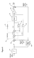
- FIG. 3 shows a block diagram of a control apparatus for controlling the phase device 10 in accordance with one embodiment of the present invention.
- the control apparatus comprises a controller 51 and a modulator 52.
- the functions of the controller 51 and modulator 52 can be implemented in the ECU 1.
- the functions are typically implemented by one or more computer programs stored in the memory 1c of the ECU 1.
- the functions may be implemented by software, hardware, firmware or any combination thereof.
- control input Vcain into the phase device 10 that is a plant (controlled object) is a command value for driving the solenoid 31.
- a control output CAIN (controlled variable) is an actual phase of the intake cam 5a relative to the crankshaft 7.
- the controller 51 calculates a manipulated variable Rcain so that the output CAIN of the phase device 10 converges to a desired value CAIN_cmd (more exactly, a modified desired value CAIN_cmd_f as described later).
- the desired value CAIN_cmd is set in accordance with a driving force requested by the driver (which is typically represented by an opening degree of the accelerator pedal) and/or an operating condition of the engine.
- the controller 51 calculates the manipulated variable Rcain by performing a 2-degree-of-freedom sliding mode control.
- Other control schemes may be used to calculate the manipulated variable Rcain.
- the 2-degree-of-freedom sliding mode control will be described later.
- the delta-sigma ( ⁇ ) modulator 52 receives the manipulated variable Rcain as a reference input.
- the delta-sigma modulator 52 uses a delta-sigma ( ⁇ ) modulation algorithm to modulate the reference input Rcain.
- the reference input Rcain is modulated to a modulated signal Vcain having switching characteristics.
- the modulated signal Vcain is a control input to be applied to the phase device 10. By virtue of the switching characteristics of the modulated signal, the phase device 10 is accurately controlled so that the controlled variable CAIN converges to the desired value CAIN_cmd.
- a sliding mode control is a response assignment control that is capable of specifying a convergence speed of a controlled variable.
- the 2-degree-of-freedom sliding mode control is an extended version of a sliding mode control. According to the 2-degree-of-freedom sliding mode control, a speed that a controlled variable follows a desired value and a speed that a controlled variable converges when disturbance is applied can be separately specified.
- the 2-degree-of-freedom sliding mode controller 51 uses a desired value response assignment parameter POLE_f to apply a first-order delay filter (a low-pass filter) to the desired value CAIN_cmd.
- the desired value response assignment parameter POLE_f specifies the speed that the controlled variable follows the desired value. It is preferably set to satisfy -1 ⁇ POLE_f ⁇ 0.
- k represents a cycle number.
- CAIN_ cmd _ f(k) -POLE_f ⁇ CAIN_cmd_f(k -1) + (1 + POLE_ f) ⁇ CAIN _ cmd(k)
- a trajectory of the desired value CAIN_cmd_f is determined by the desired value response assignment parameter POLE_f.
- the speed that the controlled variable follows the desired value can be specified in accordance with what trajectory is set for the desired value.
- the controller 51 calculates the manipulated variable Rcain so that the controlled variable CAIN converges to the desired value CAIN_cmd_f thus modified by the response assignment parameter POLE_f.
- the controller 51 defines a switching function ⁇ s as shown in the equation (2).
- Ecain is an error between the actual phase CAIN and the desired value CAIN_cmd_f.
- the switching function ⁇ s specifies a convergence behavior of the error Ecain.
- POLE is a disturbance suppressing response assignment parameter for specifying the speed that the error Ecain, which may occur when disturbance is applied, converges.
- the response assignment parameter POLE is preferably set to satisfy -1 ⁇ POLE ⁇ 0.
- the controller 51 determines the control input so that the switching function ⁇ s reaches zero.
- the equation (3) represents a first-order delay system having no input.
- the sliding mode control controls the error Ecain so that the error is confined within the first-order delay system shown in the equation (3).
- Figure 4 shows a phase plane with Ecain(k) on the vertical axis and Ecain(k-1) on the horizontal axis.
- a switching line 61 expressed by the equation (3) is shown in the phase plane.
- a point 62 is an initial value of a state quantity (Ecain(k-1), Ecain(k))
- the controller 51 places the state quantity on the switching line 61 and then constrains it on the switching line 61.
- the state quantity can converge to the origin without being influenced by disturbance.
- reference numerals 63, 64 and 65 show the convergence speed of the error Ecain when the disturbance suppressing response assignment parameter POLE takes a value of -1, -0.8 or -0.5, respectively.
- the convergence speed of the error Ecain increases as the absolute value of the response assignment parameter POLE decreases.
- the controller 51 calculates a simplified equivalent control input Rff, a reaching law input Rrch, an adaptive law input Radp and a dumper input Rdump to determine the manipulated variable Rcain.
- the simplified equivalent control input Rff can be calculated from an equivalent control input. Calculation of the equivalent control input will be described briefly.
- the equivalent control input needs to satisfy the equation (4) because it is an input for constraining the state quantity on the switching line. Assuming that a plant can be modeled as in the equation (5) (where a1, a2 and b1 are model parameters), the equation (6) can be derived by substituting the equation (5) into the equation (4).
- Vcain(k) calculated by the equation (6) is the equivalent control input.
- the equivalent control input has two functions expressed by the term (I) and the term (II).
- the term (I) indicates an input for causing the state quantity (CAIN(k), CAIN(k-1)) to settle to the desired value when the desired value is constant.
- the term (II) is a feed-forward input for improving the capability of the state quantity to follow the desired value when the desired value changes.
- the term (II) is called a simplified equivalent control input. In this embodiment, in fact, a model expression as shown in the equation (5) is not used.
- the controller 51 further calculates the reaching law input Rrch in accordance with the equation (8), the adaptive law input Radp in accordance with the equation (9) and the dumper input Rdump in accordance with the equation (10).
- the reaching law input Rrch is an input for placing the state quantity on the switching line. It is calculated as a proportional term of the switching function ⁇ s.
- the adaptive law input Radp is an input for placing the state quantity on the switching line while suppressing the steady-state error. It is calculated as an integral term of the switching function ⁇ s.
- the dumper input Rdump is an input for decelerating the actual phase CAIN when the actual phase CAIN excessively accelerates.
- Krch, Kadp and Kdump are feedback gains that are predetermined by simulation or the like.
- Rrch(k) -Krch ⁇ ⁇ s(k)
- Rdump(k) -Kdump ⁇ (CAIN(k) - CAIN(k-1))
- the controller 51 calculates a sum of the simplified equivalent control input Rff, the reaching law input Rrch, the adaptive law input Radp and the dumper input Rdump to determine the manipulated variable Rcain.
- This manipulated variable Rcain is input into the delta-sigma modulator 52 as a reference input signal.
- Rcain(k) Rff (k) + Rrch(k) + Radp(k) + Rdump(k)
- FIG. 6 shows a detailed functional block diagram of the delta-sigma modulator 52.
- the reference input signal Rcain received from the controller 51 is limited by a limiter 71 as shown in the equation (12).
- the reference input signal Rcain is limited within a range between a lower limit value (for example, 2V) and an upper limit value (for example, +7V) by a function Lim ().
- r1(k) Lim(Rcain(k))
- the phase CAIN may exhibit an abrupt change that cannot be observed in a control cycle of the controller. In order to prevent such an uncontrollable condition, the limiter 71 is provided.
- an adaptive offset value Vcain_oft_adp received from the adaptive offset generator 80 is subtracted from an output signal r1 of the limiter 71.
- r2(k) r1(k) - Vcain _ oft_ adp(k)
- a subtractor 73 calculates a difference ⁇ (k) between a signal r2(k) obtained by the offset process and the modulated signal u"(k-1) that is delayed by a delay element 75, as shown in the equation (14).
- An integrator 74 adds the difference signal ⁇ (k) and the integral ⁇ (k-1) of the difference ⁇ that is delayed by a delay element 76 to determine the integral ⁇ (k) of the difference, as shown in the equation (15).
- ⁇ (k) r2(k) - u" (k-1)
- ⁇ (k) ⁇ (k-1) + ⁇ (k)
- a non-linear function unit 77 encodes the integral signal ⁇ (k) to output a modulated signal u"(k), as shown in the equation (16).
- the encoding is performed by applying a non-linear function fn1() to the integral signal ⁇ (k), as shown in the equation (17).
- the non-linear function unit 77 outputs a signal having a value of +R when the integral ⁇ (k) is equal to or larger than zero.
- the non-linear function unit 77 units outputs a signal having a value of -R when the integral ⁇ (k) is smaller than zero.
- R is set to have a value that is larger than the maximum absolute value which the reference input signal Rcain can take.
- the non-linear function unit 77 may output a signal having a value of zero when the integral ⁇ (k) is equal to zero.
- u"(k) fnl( ⁇ (k)) where R > the max imum of
- an encoding function that outputs ⁇ 1 is used instead of the non-linear function fnl().
- a modulated signal u" held to a maximum value or a minimum value may be generated. If the frequency with which the modulated signal is held to the maximum or minimum is high, the control accuracy may deteriorate.
- Such a holding condition occurs when the signal r2 exceeds the absolute value (that is, a value of 1) of the modulated signal u" that is fed back to the subtractor 73.
- the non-linear function fnl() is introduced so that the absolute value of the modulated signal u" does not have a value of 1 but has a value R larger than the maximum value which the signal r2 can take.
- a holding condition of the modulated signal u" can be avoided even when the absolute value of the signal r2 is equal to or larger than 1.
- An amplifier 78 amplifies the modulated signal u"(k) as shown in the equation (18) to generate an amplified modulated signal u(k).
- u(k) F ⁇ u"(k)
- Vcain_oft_adp received from the adaptive offset generator 80 is added to the amplified modulated signal u(k) as shown in the equation (19) to determine the modulated signal Vcain that is to be applied to the plant.
- Vcain(k) u(k) + Vcain_ oft_ adp(k)
- an adder 72 subtracts the adaptive offset value Vcain_oft_adp from the reference input signal Rcain (more exactly, the signal r1 obtained after the limiting process).
- the adaptive offset value Vcain_oft_adp is added by an adder 79 when the control input Vcain to be input to the plant is calculated.
- the offset value used by the adders 72 and 79 is a fixed value.
- the offset value is adapted to the reference input signal Rcain.
- the adaptive offset generator 80 is provided to calculate the offset value Vcain_oft_adp adapted to the reference input signal Rcain.
- the adaptive offset value Vcain_oft_adp is calculated to follow the reference input signal Rcain.
- the modulated signal u(k) is generated as a switching signal that makes the frequency of the maximum value and the frequency of the minimum value equal (refer to Figure 7).
- the center value of the amplitude of the modulated signal u(k) becomes equal to Vcain_oft_adp(k).
- the modulated signal Vcain switches between positive and negative with respect to the center value Vcain_oft_adp.
- the amplitude of the modulated signal Vcain is determined by the value of R in the non-linear function fnl and the gain F of the amplifier 78.
- the adaptive offset value Vcain_oft_adp is generated to follow the reference input signal Rcain
- the modulated signal Vcain is also generated to follow the reference input signal Rcain.
- the adaptive offset value Vcain_oft_adp is calculated to follow the reference input signal Rcain with some response delay.
- the modulated signal Vcain is a switching signal having an amplitude D extending from -R ⁇ F to +R ⁇ F with respect to the adaptive offset value Vcain_oft_adp (R represents the parameter of the non-linear function 77 and F represents the gain of the amplifier 78 as described above).
- the phase CAIN can be appropriately controlled to follow the desired value CAIN_cmd (in Figure 8, the phase CAIN and the desired value CAIN_cmd are shown as a single line because they overlap each other).
- the adaptive offset value Vcain_oft_adp is automatically adjusted in accordance with the change of the reference input signal Rcain. Therefore, even when the reference input signal Rcain changes due to changes in the characteristics of the torque by heat generation and/or changes in the friction characteristics by variations and age deterioration in the phase device 10, the phase CAIN can accurately converge to the desired value CAIN_cmd.
- the offset value Vcain_oft_adp is calculated to adapt to the reference input signal Rcain, there is no need to magnify the amplitude D of the modulated signal so as to contain the maximum and minimum values of the reference input signal Rcain. Since the amplitude of the modulated signal Vcain to be applied to the plant does not need to be magnified, it can be avoided that the control output of the plant or the phase CAIN is destabilized.
- Figure 9 is a block diagram of the adaptive offset generator 80.
- a predetermined reference offset value Vcain_oft is subtracted from the output signal r1 of the limiter 71 ( Figure 6) to generate a signal r3.
- a non-linear function unit 82 applies a non-linear function Tnl to the signal r3 as shown in the equation (20).
- the function Tnl outputs the signal r3 when the signal r3 is within a range from (Vcain_oft_adp'(k-1)-Eps(k)) to (Vcain_oft_adp'(k-1)+Eps(k)).
- the signal r3 exceeds the upper limit value (Vcain_oft_adp'(k-1)+Eps(k)) of the range, the upper limit value is output.
- the signal r3 is below the lower limit value (Vcain_oft_adp'(k-1)-Eps(k))
- the lower limit value is output.
- the signal r3 is controlled to remain within a predetermined range where the previous offset value Vcain_oft_adp(k-1) (more exactly, Vcain_oft_adp', which is a value obtained by subtracting the reference offset value Vcain_oft from the previous adaptive offset value Vcain_oft_adp(k-1)) is positioned in the center of the range.
- Vcain_oft_adp(k-1) more exactly, Vcain_oft_adp', which is a value obtained by subtracting the reference offset value Vcain_oft from the previous adaptive offset value Vcain_oft_adp(k-1)
- the adaptive offset value Vcain_oft_adp may also exhibit an impulsive behavior. Occurrence of such impulsive behavior in the adaptive offset value Vcain_oft_adp can be avoided by applying the function Tnl.
- a non-linear filter is configured from an amplifier 83, an adder 84, a delay element 85 and an amplifier 86.
- the non-linear filter filters a signal r_tnl generated by the non-linear function unit 82 to output an offset correction value Vcain_oft_adp" as shown in the equation (21).
- G represents a filter coefficient and is set to satisfy 0 ⁇ G ⁇ 1.
- Vcain _ oft _ adp" (k) (1-G) ⁇ Vcain _ oft _ adp' (k -1) + G ⁇ r _ tnl(k)
- a limiter 87 limits the offset correction value Vcain_oft_adp" in accordance with the equation (22).
- the offset correction value Vcain_oft_adp" is limited within a range between a lower limit value (for example, -0.5V) and an upper limit value (for example, +3V) by a function Lim'().
- the reason for providing the limiter 87 is the same as for the above-described limiter 71.
- Vcain _ oft _ adp' (k) Lim' (Vcain_oft_ adp" (k))
- An adder 88 adds the reference offset value Vcain_oft to the limited offset correction value Vcain_oft_adp' to calculate the adaptive offset value Vcain_oft_adp as shown in the equation (23).
- Vcain_ oft_ adp(k) Vcain_ oft_ adp' (k) + Vcain _ oft
- the adaptive offset value Vcain_oft_adp corresponding to a difference between the reference input signal Rcain and the reference offset value Vcain_oft is calculated.
- the adaptive offset value Vcain_oft_adp follows a change in the reference input signal Rcain.
- Figure 10(a) shows the signal r1 obtained from the limiting process by the limiter 71. Abrupt changes as shown by reference numerals 91 and 92 occur in the signal r1. This means that such abrupt changes are contained in the reference input signal Rcain.
- the adaptive offset value Vcain_oft_adp can be calculated so that the adaptive offset value does not follow such abrupt changes in the signal r1 as shown by the reference numerals 91 and 92.
- Figure 10(b) shows a signal r3 obtained by subtracting the reference offset value Vcain_oft from the signal r1.
- the signal r3 is limited by the non-linear function Tnl within the predetermined range (from Vcain_oft_adp'(k-1)- Eps to Vcain_oft_adp'(k-1)+Eps) where Vcain_oft_adp'(k-1) is positioned at the center of the range.
- the signal r3 When the signal r3 exhibits an impulsive behavior and hence exceeds the predetermined range as shown at time t1, the signal r3 is limited to the upper limit value (Vcain_oft_adp'(k-1)+Eps) of the predetermined range. When the signal r3 abruptly changes and hence exceeds the predetermined range as shown at time t2, the signal r3 is limited to the upper limit value (Vcain_oft_adp'(k-1)+Eps) of the predetermined range.
- the value Vcain_oft_adp' calculated based on the output signal r_tnl smoothly changes as shown in Figure 10(b).
- the adaptive offset value Vcain_oft_adp is determined as shown in Figure 10 (a). It is seen that the adaptive offset value Vcain_oft_adp is calculated so that the adaptive offset value does not follow the abrupt changes in the signal r1 as shown by the reference numerals 91 and 92.
- FIG 11 shows a control flow in accordance with one embodiment of the present invention.
- This control flow is carried out at a predetermined time interval.
- This control flow can be carried out by the ECU 1.
- this control flow is carried out by one or more programs stored in the memory 1c of the ECU 1.
- step S1 it is determined whether the continuously variable phase device 10 is normal.
- An abnormality (such as a failure etc.) of the phase device can be detected by using any appropriate technique. If an abnormality is detected in the phase device, the control input Vcain is set to zero in step S2.
- the phase device is configured so that the actual phase CAIN of the intake camshaft is most retarded when the control input Vcain is zero.
- step S3 If it is determined in step S1 that the phase device 10 is normal, it is determined whether the engine is in the starting mode (S3). If the engine is in the starting mode, a predetermined value CAIN_cmd_st is set in the desired value CAIN_cmd in step S4. The predetermined value CAIN_cmd_st is set to be slightly advanced (for example, about 10 degrees assuming that the most retarded phase is zero degree) so as to improve in-cylinder flow.
- a map is referred to based on the engine rotational speed NE to determine the desired value CAIN_cmd in step S5.
- An example of the map is shown in Figure 12.
- the desired value CAIN_cmd is set to be more retarded.
- the requested driving force which is typically represented by an opening degree of the accelerator pedal
- the desired value CAIN_cmd is set to be more retarded.
- the phase CAIN is set to be advanced. As the phase is set to be more advanced, the overlapping time during which both of the exhaust and intake valves are open is longer, increasing the remaining gas used for the combustion.
- step S6 the control input Vcain is calculated through the above-described 2-fegree-iof-freedom sliding mode control and delta-sigma modulation performed by the controller 51 and the modulator 52.
- a sigma-delta ( ⁇ ) modulation algorithm or a delta ( ⁇ ) modulation algorithm may be used instead of the delta-sigma modulation algorithm.
- a functional block diagram of a modulator using the sigma-delta modulation algorithm is shown in Figure 13.
- Calculation performed by the sigma-delta modulation algorithm is shown in the equations (24) to (31).
- An adaptive offset value Vcain_oft_adp is calculated in accordance with the method as described above referring to Figure 9.
- FIG. 14 A functional block diagram of a modulator using the delta modulation algorithm is shown in Figure 14. Calculation performed by the delta modulation algorithm is shown in the equations (32) to (38). An adaptive offset value Vcain_oft_adp is calculated in accordance with the method as described above referring to Figure 9.
- phase of the exhaust camshaft can be controlled in a similar way to the control of the phase of the intake camshaft as described above.
- a response assignment control for example, a back-stepping control
- the manipulated variable Rcain may be calculated by using another control scheme such as a Hoo control or an optimum control.
- control scheme in accordance with the present invention can be applied to various controlled objects. It should be noted that the control scheme in accordance with the present invention is not limited to the engine of the vehicle.
- a controlled object is a system extending from a control mechanism for controlling an air/fuel ratio of an engine to an exhaust gas sensor (for example, the 02 sensor shown in Figure 1) that is disposed in an exhaust manifold of the engine.
- a controller calculates a manipulated variable to be used for controlling the air/fuel ratio of the engine so that the output of the exhaust gas sensor converges to a desired value.
- the manipulated variable is, for example, an amount of fuel to be supplied to the engine.
- the control mechanism drives a fuel injection valve 19 ( Figure 1) so that the amount of fuel thus calculated is supplied to the engine.
- the air/fuel ratio of the engine is appropriately controlled.
- a controlled object is an actuator for variably controlling a lift amount of an intake valve and/or an exhaust valve of an engine.
- a controller calculates a manipulated variable so that the lift amount of the valve converges to a desired value.
- the actuator changes the lift amount of the valve in accordance with the manipulated variable. Thus, the amount of air to be taken into the engine can be appropriately controlled.
- the present invention can be applied to a general-purpose engine (for example, an outboard motor).
- a general-purpose engine for example, an outboard motor.
- the invention provides a control apparatus comprising a controller for determining a manipulated variable for manipulating a controlled object so that an output of the controlled object converges to a desired value and a modulator for modulating the manipulated variable by using one of a delta-sigma modulation algorithm, a sigma-delta modulation algorithm and a delta modulation algorithm to generate a modulated signal to be applied to the controlled object.
- the modulator generates the modulated signal so that a center value of an amplitude of the modulated signal follows a change of the manipulated variable.
Abstract
Description


Claims (14)
- A control apparatus comprising:a controller for determining a manipulated variable for manipulating a controlled object to cause an output of the controlled object to converge to a desired value; anda modulator for modulating the manipulated variable by using one of a delta-sigma modulation algorithm, a sigma-delta modulation algorithm and a delta modulation algorithm to generate a modulated signal that is to be applied to the controlled object, the modulated signal being generated so that a center value of an amplitude of the modulated signal follows a change of the manipulated variable.
- The control apparatus of claim 1, wherein the modulator includes an adaptive offset generator for generating an adaptive offset value based on the manipulated variable, and
wherein the modulator generates the modulated signal so that the adaptive offset value is the center value of the amplitude of the modulated signal. - The control apparatus of claim 2, wherein the adaptive offset generator includes a filter for filtering the manipulated variable to suppress an abrupt change of the adaptive offset value, and
wherein the adaptive offset generator generates the adaptive offset value based on an output from the filter. - The control apparatus of claim 3, wherein the adaptive offset generator further includes a unit for limiting the manipulated variable within a predetermined range, the predetermined range being determined based on a past value of the adaptive offset value, and
wherein the filter filters the limited manipulated variable. - The control apparatus of claim 1, wherein:the controlled object is a phase mechanism for changing a phase of a cam of an engine;the output of the controlled object is the phase of the cam; andthe phase mechanism changes the phase of the cam in accordance with the modulated signal.
- The control apparatus of claim 1, wherein:the controlled object is a lift mechanism for changing a lift amount of a valve of an engine;the output of the controlled object is the lift amount of the valve; andthe lift mechanism changes the lift amount of the valve in accordance with the modulated signal.
- The control apparatus of claim 1, wherein:the controlled object is a system extending from a control mechanism for controlling an air/fuel ratio of an engine to an exhaust gas sensor disposed in an exhaust manifold of the engine;the output of the controlled object is an output of the exhaust gas sensor; andthe control mechanism changes the air/fuel ratio of the engine in accordance with the modulated signal.
- A method for controlling a controlled object, the method comprising the steps of:determining a manipulated variable for manipulating the controlled object to cause an output of the controlled object to converge to a desired value;modulating the manipulated variable by using one of a delta-sigma modulation algorithm, a sigma-delta modulation algorithm and a delta modulation algorithm; andthrough the modulation of the manipulated variable, generating a modulated signal that is to be applied to the controlled object so that a center value of an amplitude of the modulated signal follows a change of the manipulated variable.
- The method of claim 8, further comprising the step of generating an adaptive offset value based on the manipulated variable,
wherein the step of generating a modulated signal includes generating the modulated signal so that the adaptive offset value is the center value of the amplitude of the modulated signal. - The method of claim 9, further comprising the step of filtering the manipulated variable to suppress an abrupt change of the adaptive offset value,
wherein the step of generating an adaptive offset value includes generating the adaptive offset value based on an output from the filtering. - The method of claim 10, further comprising the step of limiting the manipulated variable within a predetermined range, the predetermined range being determined based on a past value of the adaptive offset value,
wherein the step of filtering includes filtering the limited manipulated variable. - The method of claim 8, wherein:the controlled object is a phase mechanism for changing a phase of a cam of an engine;the output of the controlled object is the phase of the cam; andthe method further comprises the step of changing the phase of the cam by the phase mechanism in accordance with the modulated signal.
- The method of claim 8, wherein:the controlled object is a lift mechanism for changing a lift amount of a valve of an engine;the output of the controlled object is the lift amount of the valve; andthe method further comprises the step of changing the lift amount of the valve by the lift mechanism in accordance with the modulated signal.
- The method of claim 8, wherein:the controlled object is a system extending from a control mechanism for controlling an air/fuel ratio of an engine to an exhaust gas sensor disposed in an exhaust manifold of the engine;the output of the controlled object is an output of the exhaust gas sensor; andthe method further comprises the step of changing the air/fuel ratio of the engine by the control mechanism in accordance with the modulated signal.
Applications Claiming Priority (2)
| Application Number | Priority Date | Filing Date | Title |
|---|---|---|---|
| JP2004070312 | 2004-03-12 | ||
| JP2004070312 | 2004-03-12 |
Publications (2)
| Publication Number | Publication Date |
|---|---|
| EP1574695A2 true EP1574695A2 (en) | 2005-09-14 |
| EP1574695A3 EP1574695A3 (en) | 2011-08-31 |
Family
ID=34824619
Family Applications (1)
| Application Number | Title | Priority Date | Filing Date |
|---|---|---|---|
| EP20050001449 Withdrawn EP1574695A3 (en) | 2004-03-12 | 2005-01-25 | A control apparatus for controlling a plant by using a delta-sigma modulation algorithm |
Country Status (4)
| Country | Link |
|---|---|
| US (1) | US7133763B2 (en) |
| EP (1) | EP1574695A3 (en) |
| CN (1) | CN100495260C (en) |
| TW (1) | TW200600985A (en) |
Cited By (3)
| Publication number | Priority date | Publication date | Assignee | Title |
|---|---|---|---|---|
| US7133763B2 (en) * | 2004-03-12 | 2006-11-07 | Honda Motor Co., Ltd. | Control apparatus for controlling a plant by using a delta-sigma modulation algorithm |
| EP1729189A1 (en) * | 2004-03-23 | 2006-12-06 | HONDA MOTOR CO., Ltd. | Plant control device and control method using modulation algorithm |
| EP1973015A3 (en) * | 2003-08-08 | 2008-10-29 | Honda Motor Co., Ltd | Control system based on a delta, delta-sigma or sigma-delta modulation algorithm |
Families Citing this family (16)
| Publication number | Priority date | Publication date | Assignee | Title |
|---|---|---|---|---|
| JP4486901B2 (en) * | 2005-02-23 | 2010-06-23 | 本田技研工業株式会社 | Control device |
| US8701628B2 (en) | 2008-07-11 | 2014-04-22 | Tula Technology, Inc. | Internal combustion engine control for improved fuel efficiency |
| US8646435B2 (en) * | 2008-07-11 | 2014-02-11 | Tula Technology, Inc. | System and methods for stoichiometric compression ignition engine control |
| US8402942B2 (en) * | 2008-07-11 | 2013-03-26 | Tula Technology, Inc. | System and methods for improving efficiency in internal combustion engines |
| US8616181B2 (en) | 2008-07-11 | 2013-12-31 | Tula Technology, Inc. | Internal combustion engine control for improved fuel efficiency |
| US9020735B2 (en) | 2008-07-11 | 2015-04-28 | Tula Technology, Inc. | Skip fire internal combustion engine control |
| US8131447B2 (en) * | 2008-07-11 | 2012-03-06 | Tula Technology, Inc. | Internal combustion engine control for improved fuel efficiency |
| US7577511B1 (en) | 2008-07-11 | 2009-08-18 | Tula Technology, Inc. | Internal combustion engine control for improved fuel efficiency |
| US8336521B2 (en) * | 2008-07-11 | 2012-12-25 | Tula Technology, Inc. | Internal combustion engine control for improved fuel efficiency |
| US8511281B2 (en) | 2009-07-10 | 2013-08-20 | Tula Technology, Inc. | Skip fire engine control |
| US8401676B2 (en) * | 2010-08-18 | 2013-03-19 | International Business Machines Corporation | Performance improvement of signal transformation schemes for ultra-fast scanning |
| US8869773B2 (en) | 2010-12-01 | 2014-10-28 | Tula Technology, Inc. | Skip fire internal combustion engine control |
| US9163569B2 (en) * | 2011-08-25 | 2015-10-20 | GM Global Technology Operations LLC | Indirect HCCI combustion control |
| JP5351304B2 (en) * | 2012-04-19 | 2013-11-27 | ファナック株式会社 | Motor control device having ΔΣ modulation type AD converter |
| US9291106B2 (en) | 2013-03-15 | 2016-03-22 | Tula Technology, Inc. | Cam phaser control |
| CN103762990B (en) * | 2014-01-13 | 2017-01-25 | 东南大学 | Sigma delta modulator structure with noise suppression capacity enhanced |
Citations (1)
| Publication number | Priority date | Publication date | Assignee | Title |
|---|---|---|---|---|
| JP2003195908A (en) | 2001-12-28 | 2003-07-11 | Honda Motor Co Ltd | Control device |
Family Cites Families (8)
| Publication number | Priority date | Publication date | Assignee | Title |
|---|---|---|---|---|
| EP0666650A3 (en) * | 1994-01-24 | 1997-08-13 | Siemens Ag | Method for the fast decoding of the output signals of sigma delta modulators. |
| US6885326B2 (en) * | 1999-02-04 | 2005-04-26 | Med-El Elektromedizinische Geraeta Gmbh | Accumulator for adaptive Σ-Δ modulation |
| EP1488525B1 (en) * | 2002-03-28 | 2010-08-18 | Med-El Elektromedizinische Geräte GmbH | A system and method for adaptive sigma-delta modulation |
| JP3926703B2 (en) * | 2002-08-08 | 2007-06-06 | 本田技研工業株式会社 | Control device |
| JP3957180B2 (en) * | 2002-08-09 | 2007-08-15 | 本田技研工業株式会社 | Air-fuel ratio control apparatus for internal combustion engine using decimation filter |
| JP4121914B2 (en) * | 2003-08-08 | 2008-07-23 | 本田技研工業株式会社 | Control device |
| JP4181006B2 (en) * | 2003-10-03 | 2008-11-12 | 本田技研工業株式会社 | A control device for controlling a plant using a ΔΣ modulation algorithm |
| EP1574695A3 (en) * | 2004-03-12 | 2011-08-31 | Honda Motor Co., Ltd. | A control apparatus for controlling a plant by using a delta-sigma modulation algorithm |
-
2005
- 2005-01-25 EP EP20050001449 patent/EP1574695A3/en not_active Withdrawn
- 2005-02-01 TW TW094103099A patent/TW200600985A/en unknown
- 2005-02-04 US US11/050,646 patent/US7133763B2/en not_active Expired - Fee Related
- 2005-03-10 CN CNB2005100537031A patent/CN100495260C/en not_active Expired - Fee Related
Patent Citations (1)
| Publication number | Priority date | Publication date | Assignee | Title |
|---|---|---|---|---|
| JP2003195908A (en) | 2001-12-28 | 2003-07-11 | Honda Motor Co Ltd | Control device |
Cited By (4)
| Publication number | Priority date | Publication date | Assignee | Title |
|---|---|---|---|---|
| EP1973015A3 (en) * | 2003-08-08 | 2008-10-29 | Honda Motor Co., Ltd | Control system based on a delta, delta-sigma or sigma-delta modulation algorithm |
| US7133763B2 (en) * | 2004-03-12 | 2006-11-07 | Honda Motor Co., Ltd. | Control apparatus for controlling a plant by using a delta-sigma modulation algorithm |
| EP1729189A1 (en) * | 2004-03-23 | 2006-12-06 | HONDA MOTOR CO., Ltd. | Plant control device and control method using modulation algorithm |
| EP1729189A4 (en) * | 2004-03-23 | 2010-07-21 | Honda Motor Co Ltd | Plant control device and control method using modulation algorithm |
Also Published As
| Publication number | Publication date |
|---|---|
| US20050203642A1 (en) | 2005-09-15 |
| EP1574695A3 (en) | 2011-08-31 |
| CN1667530A (en) | 2005-09-14 |
| US7133763B2 (en) | 2006-11-07 |
| TW200600985A (en) | 2006-01-01 |
| CN100495260C (en) | 2009-06-03 |
Similar Documents
| Publication | Publication Date | Title |
|---|---|---|
| EP1574695A2 (en) | A control apparatus for controlling a plant by using a delta-sigma modulation algorithm | |
| US7058501B2 (en) | Control apparatus for controlling a plant by using a delta-sigma modulation | |
| US7316212B2 (en) | Cam phase control system for internal combustion engine | |
| US7403849B1 (en) | Control apparatus for an internal combustion engine | |
| US7493207B2 (en) | Control apparatus, control method, and engine control unit | |
| JP4145520B2 (en) | Cam phase control device for internal combustion engine | |
| US7143728B1 (en) | Control apparatus | |
| US7158874B2 (en) | Controller | |
| JP2006233822A (en) | Controller | |
| US6386158B1 (en) | Valve timing control apparatus for internal combustion engines | |
| EP1653304B1 (en) | Controller | |
| JP4598474B2 (en) | Plant control equipment | |
| EP1669822B1 (en) | Device and method for controlling a plant by using an identifier for partially identifying a model parameter | |
| JP4414360B2 (en) | Control device for controlling a plant using a predetermined modulation algorithm | |
| JP4630354B2 (en) | A control device for controlling a plant using a ΔΣ modulation algorithm | |
| JP4060767B2 (en) | Control device | |
| US20070062471A1 (en) | Controller for plant using PWM algorithm |
Legal Events
| Date | Code | Title | Description |
|---|---|---|---|
| PUAI | Public reference made under article 153(3) epc to a published international application that has entered the european phase |
Free format text: ORIGINAL CODE: 0009012 |
|
| AK | Designated contracting states |
Kind code of ref document: A2 Designated state(s): AT BE BG CH CY CZ DE DK EE ES FI FR GB GR HU IE IS IT LI LT LU MC NL PL PT RO SE SI SK TR |
|
| AX | Request for extension of the european patent |
Extension state: AL BA HR LV MK YU |
|
| PUAL | Search report despatched |
Free format text: ORIGINAL CODE: 0009013 |
|
| AK | Designated contracting states |
Kind code of ref document: A3 Designated state(s): AT BE BG CH CY CZ DE DK EE ES FI FR GB GR HU IE IS IT LI LT LU MC NL PL PT RO SE SI SK TR |
|
| AX | Request for extension of the european patent |
Extension state: AL BA HR LV MK YU |
|
| RIC1 | Information provided on ipc code assigned before grant |
Ipc: F01L 25/08 20060101ALN20110725BHEP Ipc: F02D 41/14 20060101ALN20110725BHEP Ipc: G05B 13/02 20060101AFI20110725BHEP |
|
| STAA | Information on the status of an ep patent application or granted ep patent |
Free format text: STATUS: THE APPLICATION IS DEEMED TO BE WITHDRAWN |
|
| 18D | Application deemed to be withdrawn |
Effective date: 20110802 |