EP1574671B1 - Moteur à turbine - Google Patents
Moteur à turbine Download PDFInfo
- Publication number
- EP1574671B1 EP1574671B1 EP05005302.4A EP05005302A EP1574671B1 EP 1574671 B1 EP1574671 B1 EP 1574671B1 EP 05005302 A EP05005302 A EP 05005302A EP 1574671 B1 EP1574671 B1 EP 1574671B1
- Authority
- EP
- European Patent Office
- Prior art keywords
- blades
- turbine engine
- stationary
- row
- rotating
- Prior art date
- Legal status (The legal status is an assumption and is not a legal conclusion. Google has not performed a legal analysis and makes no representation as to the accuracy of the status listed.)
- Expired - Fee Related
Links
Images

Classifications
-
- F—MECHANICAL ENGINEERING; LIGHTING; HEATING; WEAPONS; BLASTING
- F16—ENGINEERING ELEMENTS AND UNITS; GENERAL MEASURES FOR PRODUCING AND MAINTAINING EFFECTIVE FUNCTIONING OF MACHINES OR INSTALLATIONS; THERMAL INSULATION IN GENERAL
- F16J—PISTONS; CYLINDERS; SEALINGS
- F16J15/00—Sealings
- F16J15/16—Sealings between relatively-moving surfaces
- F16J15/40—Sealings between relatively-moving surfaces by means of fluid
- F16J15/406—Sealings between relatively-moving surfaces by means of fluid by at least one pump
-
- F—MECHANICAL ENGINEERING; LIGHTING; HEATING; WEAPONS; BLASTING
- F01—MACHINES OR ENGINES IN GENERAL; ENGINE PLANTS IN GENERAL; STEAM ENGINES
- F01D—NON-POSITIVE DISPLACEMENT MACHINES OR ENGINES, e.g. STEAM TURBINES
- F01D11/00—Preventing or minimising internal leakage of working-fluid, e.g. between stages
- F01D11/02—Preventing or minimising internal leakage of working-fluid, e.g. between stages by non-contact sealings, e.g. of labyrinth type
-
- F—MECHANICAL ENGINEERING; LIGHTING; HEATING; WEAPONS; BLASTING
- F16—ENGINEERING ELEMENTS AND UNITS; GENERAL MEASURES FOR PRODUCING AND MAINTAINING EFFECTIVE FUNCTIONING OF MACHINES OR INSTALLATIONS; THERMAL INSULATION IN GENERAL
- F16J—PISTONS; CYLINDERS; SEALINGS
- F16J15/00—Sealings
- F16J15/16—Sealings between relatively-moving surfaces
- F16J15/164—Sealings between relatively-moving surfaces the sealing action depending on movements; pressure difference, temperature or presence of leaking fluid
-
- F—MECHANICAL ENGINEERING; LIGHTING; HEATING; WEAPONS; BLASTING
- F16—ENGINEERING ELEMENTS AND UNITS; GENERAL MEASURES FOR PRODUCING AND MAINTAINING EFFECTIVE FUNCTIONING OF MACHINES OR INSTALLATIONS; THERMAL INSULATION IN GENERAL
- F16J—PISTONS; CYLINDERS; SEALINGS
- F16J15/00—Sealings
- F16J15/44—Free-space packings
Definitions
- This invention is directed generally to turbine engines comprising seals, and more particularly, seals usable between a rotatable body and a hollow body in a turbine engine.
- a seal is often needed to separate high pressure regions from low pressure regions between components whereby one of the components Is stationary and an adjacent component rotates.
- a common location for separating high pressure compressor gases and low pressure gases is between a rotor assembly, which rotates, and a stator assembly, which remains relatively stationary during operation of a turbine engine.
- a conventional seal used between rotatable and stationary components of a turbine engine comprised of a labyrinth seal having a plurality of ridges extending from a rotatable body.
- the ridges are sized to initially contact the opposing stationary body and to cut grooves into the stationary body.
- the ridges simply rotate within the grooves.
- the ridges prevent some gases, but not all gases, from passing between the gap created between the ridges and the grooves.
- the labyrinth seal Is susceptible to leakage and results in inefficiencies in the turbine engine in which the seal is used.
- This invention relates to a turbine engine according to claim 1 comprising a seal for sealing a high pressure region of gases from a low pressure region of gases in a turbine engine and particularly, usable between a stationary component of the turbine engine, such as, but not limited to a stator, and a rotatable component of the turbine engine, such as, but not limited to a rotor.
- the seal may be formed from a plurality of blades extending radially from a rotatable body and generally forming at least one row of blades.
- the seal may also include a plurality of blades extending radially from a stationary body towards the rotatable body and may generally form at least one row of blades.
- the plurality of blades extending radially from the stationary body may be positioned proximate to the plurality of blades extending from the rotatable body and aligned in a nonparallel configuration with the plurality of blades extending from the rotatable body.
- the blades extending from the rotatable body may be aligned relative to a rotational axis of the rotatable body such that downstream edges of the blades may be advanced relative to upstream edges of the blades in relation to a direction of rotation of the rotatable body.
- rotation of the rotatable body produces aerodynamic forces opposing the leakage flow, which tend to drive gases toward the blades extending from the stationary body.
- the plurality of blades extending from the stationary body may be aligned generally opposite to the blades extending from the rotatable body. This configuration of blades creates aerodynamic forces opposing the leakage flow; thus, increasing the resistance to leakage and reducing the amount of flow that leaks past the arrangement to any desired level.
- these aerodynamic forces substantially prevent a gas from passing from a high pressure region to a low pressure region by flowing between the rotatable and stationary bodies.
- This configuration is advantageous in that the configuration substantially prevents leakage of gases from a high pressure region to a low pressure region without using movable components that are susceptible to wear from contacting adjacent stationary components.
- this configuration is advantageous in that the configuration substantially prevents leakage of gases past the seal.
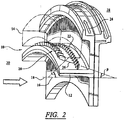
- this invention is directed to a seal 10 usable in turbine engines.
- the seal 10 may be used to form a seal between a rotatable body 12 and a stationary body 14 in a turbine engine.
- the seal 10 creates a reverse flow that is counter to the flow from a high pressure region 30 to a low pressure region 28.
- the reverse flow substantially prevents gases from flowing from the high pressure region 30 of a turbine engine to a low pressure region 28 of the turbine engine between rotatable and stationary components of the turbine engine.
- the rotatable body 12 may be, but is not limited to, a rotor assembly of a turbine engine
- the stationary body 14 may be, but is not limited to, a stator of a turbine engine.
- the seal 10 is not limited to being used only between a rotor assembly and a stator, but may be used in other locations in a turbine engine as well.
- the seal 10 may be used in turbine vane housings, compressor stator wells, thrust pistons, bearing compartments, shaft seals and any location where labyrinth seals, brush seals, or leaf seals are currently used.
- the seal 10 may also be used in other mechanical devices such as steam turbines, rocket engines, etc.
- the seal 10 may be formed from a plurality of blades 16 that extend radially from the rotatable body 12.
- the blades 16 may form one or more rows, as shown in Figure 2 . While only a single row of blades 16 is shown in Figure 2 , a plurality of rows may be used in other embodiments.
- the blades 16 may also be aligned at an angle ⁇ of between about 1 degrees and about 89 degrees relative to a rotational axis 18 of the rotatable body 12. In at least one embodiment, the blades 16 may be aligned at an angle of about 60 degrees relative to the rotational axis. As shown in Figure 2 , the blades 16, in at least one embodiment, may be substantially parallel to each other.
- the blades 16 may extend to be in close proximity with the stationary body 14. For instance, the blades 16 may extend from the rotatable body 12 to be within about 0.6 millimeters radially from the stationary body 14.
- the seal 10 also includes a plurality of blades 20 extending from the stationary body 14 towards the rotatable body 12.
- the blades 20 may form a single row, as shown in Figure 2 , or a plurality of rows.
- the blades 20 may also be aligned at an angle ⁇ of between about 1 degrees and about 89 degrees relative to a rotational axis 18 of the rotatable body 12.
- the blades 16 may aligned at an angle of about 60 degrees relative to the rotational axis.
- the angles ⁇ and ⁇ are measured from the rotational axis 18. However, the blades 16 and 20 are not parallel as the angle ⁇ is measured oppositely from the angle ⁇ .
- the plurality of blades 16 may be generally orthogonal to the plurality of blades 20.
- the blades 20 extend from the stationary body 14 toward the rotatable body 12, and the blades 20 may extend to be about 0.6 millimeters radially from the rotatable body 12. It is desirable to minimize the axial distance between the plurality of stationary and rotating blades 20 and 16 as that tends to minimize the leakage level, which is a typical design goal. However, the seal 10 can be effective even with fairly large axial gaps.
- each blade 16 is positioned on the rotatable body 12 such that a downstream edge 22 of each blade of the plurality of blades 16 is advanced in a direction of rotation, as shown by arrow 24, more than the upstream edges 26 of the blades 20.
- the row of blades 16 attached to the rotatable body 12 rotate relative to the rotational axis 18. This motion produces a force in the direction to oppose gas flow from the high pressure region 30 of the turbine engine toward the low pressure region 28.
- the rotational motion of the rotatable body 12 and the blades 16 produces forces opposing leakage from the high pressure region 30 to the low pressure region 28.
- the net flow of air past the seal 10 from the high pressure region 30 to the low pressure region 28 is between about zero to a small amount of flow.
- the design can be adjusted to allow any desired amount of leakage.
Claims (7)
- Moteur à turbine comprenant un joint d'étanchéité (10), le joint d'étanchéité (10) comprenant :une pluralité d'aubes rotatives (16) s'étendant, dans le plan radial, depuis un corps tournant (12) et formant globalement une rangée d'aubes rotatives (16), le corps tournant (12) ayant un axe de rotation (18), les aubes rotatives (16) de la rangée d'aubes rotatives (16) étant espacées les unes par rapport aux autres dans la direction circonférentielle dans le moteur à turbine, etune pluralité d'aubes fixes (20) s'étendant, dans le plan radial, depuis un corps fixe (14) vers le corps tournant (12) et formant globalement une rangée d'aubes fixes (20), les aubes fixes (20) de la rangée d'aubes fixes (20) étant espacées les unes par rapport aux autres dans la direction circonférentielle dans le moteur à turbine,étant entendu que la pluralité d'aubes fixes (20) est positionnée à proximité de la pluralité d'aubes rotatives (16) et est non parallèle à la pluralité d'aubes rotatives (16) ;
étant entendu que la pluralité d'aubes fixes (20) est alignée sous un angle (β) faisant entre environ 1 degré et environ 89 degrés par rapport à l'axe de rotation (18) ;
étant entendu que le joint d'étanchéité (10) est disposé dans le moteur à turbine entre des zones de gaz à basse et à haute pression (28, 30), la rangée d'aubes rotatives (16) étant disposée entre la zone (28) de gaz à basse pression et la rangée d'aubes fixes (20), la rangée d'aubes fixes (20) étant disposée entre la zone (30) de gaz à haute pression et la rangée d'aubes rotatives (16) ;
étant entendu que chaque aube rotative (16) de la rangée d'aubes rotatives (16) fait un angle avec l'axe de rotation (18) de telle sorte qu'un bord aval (22) de l'aube rotative (16) soit plus avancé dans un sens de rotation (24) du corps tournant (12) qu'un bord amont (26) de l'aube rotative (16), moyennant quoi la rotation de la rangée d'aubes rotatives (16) produit une force qui s'oppose à la fuite de gaz depuis la zone (30) de gaz à haute pression jusqu'à la zone (28) de gaz à basse pression. - Moteur à turbine selon la revendication 1, étant entendu que la pluralité d'aubes fixes (20) est globalement orthogonale à la pluralité d'aubes rotatives (16).
- Moteur à turbine selon la revendication 1, étant entendu que la pluralité d'aubes rotatives (16) est alignée selon un angle (α) faisant entre environ 1 degré et environ 89 degrés par rapport à l'axe de rotation (18).
- Moteur à turbine selon la revendication 3, étant entendu que la pluralité d'aubes rotatives (16) est alignée selon un angle (α) d'environ 60 degrés par rapport à l'axe de rotation (18).
- Moteur à turbine selon la revendication 1, étant entendu que la pluralité d'aubes fixes (20) est alignée selon un angle (β) d'environ 60 degrés par rapport à l'axe de rotation (18).
- Moteur à turbine selon la revendication 1, étant entendu que la pluralité d'aubes rotatives (16) s'étend, dans le plan radial, jusqu'à environ 0,6 millimètre du corps fixe (14) .
- Moteur à turbine selon la revendication 1, étant entendu que la pluralité d'aubes fixes (20) s'étend, dans le plan radial, jusqu'à environ 0,6 millimètre du corps rotatif (12) .
Applications Claiming Priority (2)
| Application Number | Priority Date | Filing Date | Title |
|---|---|---|---|
| US797452 | 2004-03-10 | ||
| US10/797,452 US20050200080A1 (en) | 2004-03-10 | 2004-03-10 | Seal for a turbine engine |
Publications (3)
| Publication Number | Publication Date |
|---|---|
| EP1574671A2 EP1574671A2 (fr) | 2005-09-14 |
| EP1574671A3 EP1574671A3 (fr) | 2013-05-29 |
| EP1574671B1 true EP1574671B1 (fr) | 2019-01-16 |
Family
ID=34827633
Family Applications (1)
| Application Number | Title | Priority Date | Filing Date |
|---|---|---|---|
| EP05005302.4A Expired - Fee Related EP1574671B1 (fr) | 2004-03-10 | 2005-03-10 | Moteur à turbine |
Country Status (2)
| Country | Link |
|---|---|
| US (1) | US20050200080A1 (fr) |
| EP (1) | EP1574671B1 (fr) |
Families Citing this family (9)
| Publication number | Priority date | Publication date | Assignee | Title |
|---|---|---|---|---|
| US8740563B2 (en) | 2010-11-22 | 2014-06-03 | General Electric Company | Sealing assembly for use in turbomachines and methods of assembling same |
| US9359908B2 (en) | 2014-07-08 | 2016-06-07 | General Electric Company | Film riding seal assembly for turbomachinery |
| US10161259B2 (en) | 2014-10-28 | 2018-12-25 | General Electric Company | Flexible film-riding seal |
| FR3079868B1 (fr) * | 2018-04-05 | 2020-11-06 | Safran Aircraft Engines | Lechette d'etancheite entre rotor et stator et turbine ainsi equipee |
| US11378187B2 (en) * | 2019-01-03 | 2022-07-05 | Raytheon Technologies Corporation | Articulating cantilevered hydrostatic seal |
| US10995861B2 (en) | 2019-01-03 | 2021-05-04 | Raytheon Technologies Corporation | Cantilevered hydrostatic advanced low leakage seal |
| US10982770B2 (en) | 2019-01-03 | 2021-04-20 | Raytheon Technologies Corporation | Hydrostatic seal with extended housing |
| US10961858B2 (en) * | 2019-01-04 | 2021-03-30 | Raytheon Technologies Corporation | Hydrostatic seal with enhanced maneuver response |
| US10975713B2 (en) | 2019-01-04 | 2021-04-13 | Raytheon Technologies Corporation | Hydrostatic seal with aft tooth |
Citations (4)
| Publication number | Priority date | Publication date | Assignee | Title |
|---|---|---|---|---|
| US1689735A (en) * | 1923-10-05 | 1928-10-30 | Losel Franz | Labyrinth gland construction |
| US3575523A (en) * | 1968-12-05 | 1971-04-20 | Us Navy | Labyrinth seal for axial flow fluid machines |
| US5102298A (en) * | 1989-09-12 | 1992-04-07 | Asea Brown Boveri Ltd. | Axial flow turbine |
| US6027306A (en) * | 1997-06-23 | 2000-02-22 | General Electric Company | Turbine blade tip flow discouragers |
Family Cites Families (24)
| Publication number | Priority date | Publication date | Assignee | Title |
|---|---|---|---|---|
| CH134451A (de) * | 1928-01-07 | 1929-07-31 | Oerlikon Maschf | Vorrichtung zur Verminderung von Spaltverlusten zwischen Turbinenleit- und Laufrädern. |
| US2587077A (en) * | 1948-06-25 | 1952-02-26 | Martin P Winther | Labyrinth seal |
| US2930521A (en) * | 1955-08-17 | 1960-03-29 | Gen Motors Corp | Gas turbine structure |
| US3476396A (en) * | 1964-04-14 | 1969-11-04 | Daimler Benz Ag | Shaft seal with return rifling |
| FR1502832A (fr) * | 1966-09-26 | 1967-11-24 | Nord Aviation | Hélice carénée à diffusion |
| US3574478A (en) * | 1968-10-21 | 1971-04-13 | Laval Turbine | Sealing system for turbine and compressor bearings |
| US3656862A (en) * | 1970-07-02 | 1972-04-18 | Westinghouse Electric Corp | Segmented seal assembly |
| US4370094A (en) * | 1974-03-21 | 1983-01-25 | Maschinenfabrik Augsburg-Nurnberg Aktiengesellschaft | Method of and device for avoiding rotor instability to enhance dynamic power limit of turbines and compressors |
| US4326835A (en) * | 1979-10-29 | 1982-04-27 | General Motors Corporation | Blade platform seal for ceramic/metal rotor assembly |
| FR2481377A1 (fr) * | 1980-04-24 | 1981-10-30 | Volta Pierre | Dispositif d'etancheite sans friction pour pompe centrifuge verticale a corps immerge |
| DE3308140C2 (de) * | 1983-03-08 | 1985-12-19 | MTU Motoren- und Turbinen-Union München GmbH, 8000 München | Mehrstufige Gasturbine |
| FR2558900B1 (fr) * | 1984-02-01 | 1988-05-27 | Snecma | Dispositif d'etancheite peripherique d'aubage de compresseur axial |
| DE3505491A1 (de) * | 1985-02-16 | 1986-08-21 | MTU Motoren- und Turbinen-Union München GmbH, 8000 München | Dichtung fuer eine stroemungsmaschine |
| US5029876A (en) * | 1988-12-14 | 1991-07-09 | General Electric Company | Labyrinth seal system |
| US5197281A (en) * | 1990-04-03 | 1993-03-30 | General Electric Company | Interstage seal arrangement for airfoil stages of turbine engine counterrotating rotors |
| GB9201762D0 (en) * | 1992-01-28 | 1992-03-11 | Wes Technology Inc | Seals for gas isolators |
| US6273429B1 (en) * | 1998-07-09 | 2001-08-14 | Atlas Copco Aktiebolag | Labyrinth cartridge seal, and centrifugal compressor applications thereof |
| US6394459B1 (en) * | 2000-06-16 | 2002-05-28 | General Electric Company | Multi-clearance labyrinth seal design and related process |
| US6467773B1 (en) * | 2000-08-31 | 2002-10-22 | Atlas Copco Comptec Inc. | Liquid seal |
| US6644667B2 (en) * | 2001-02-23 | 2003-11-11 | Cmg Tech, Llc | Seal assembly and rotary machine containing such seal |
| US6554562B2 (en) * | 2001-06-15 | 2003-04-29 | Honeywell International, Inc. | Combustor hot streak alignment for gas turbine engine |
| US6540479B2 (en) * | 2001-07-16 | 2003-04-01 | William C. Liao | Axial flow fan |
| US6786487B2 (en) * | 2001-12-05 | 2004-09-07 | General Electric Company | Actuated brush seal |
| DE10228003A1 (de) * | 2002-06-22 | 2004-01-15 | Daimlerchrysler Ag | Turbine für einen Abgasturbolader |
-
2004
- 2004-03-10 US US10/797,452 patent/US20050200080A1/en not_active Abandoned
-
2005
- 2005-03-10 EP EP05005302.4A patent/EP1574671B1/fr not_active Expired - Fee Related
Patent Citations (4)
| Publication number | Priority date | Publication date | Assignee | Title |
|---|---|---|---|---|
| US1689735A (en) * | 1923-10-05 | 1928-10-30 | Losel Franz | Labyrinth gland construction |
| US3575523A (en) * | 1968-12-05 | 1971-04-20 | Us Navy | Labyrinth seal for axial flow fluid machines |
| US5102298A (en) * | 1989-09-12 | 1992-04-07 | Asea Brown Boveri Ltd. | Axial flow turbine |
| US6027306A (en) * | 1997-06-23 | 2000-02-22 | General Electric Company | Turbine blade tip flow discouragers |
Also Published As
| Publication number | Publication date |
|---|---|
| US20050200080A1 (en) | 2005-09-15 |
| EP1574671A3 (fr) | 2013-05-29 |
| EP1574671A2 (fr) | 2005-09-14 |
Similar Documents
| Publication | Publication Date | Title |
|---|---|---|
| EP1574671B1 (fr) | Moteur à turbine | |
| EP1967700B1 (fr) | Moteur de turbine à gaz muni d'un joint d'étanchéité à labyrinthe pourvu de poches et de lamelles inclinées | |
| EP1930551B1 (fr) | Étage de turbine et moteur à turbine à gaz associé | |
| CN101382077B (zh) | 迷宫式压缩密封件和包括所述迷宫式压缩密封件的涡轮机 | |
| US6164655A (en) | Method and arrangement for sealing off a separating gap, formed between a rotor and a stator, in a non-contacting manner | |
| EP2659112B1 (fr) | Moteur à turbine à gaz et système d'ailettes à cambrure variable | |
| CN101131101B (zh) | 天使翅膀形耐磨的密封件和密封方法 | |
| US20090160135A1 (en) | Labyrinth seal with reduced leakage flow by grooves and teeth synergistic action | |
| US20120230818A1 (en) | Airfoil and corresponding guide vane, blade, gas turbine and turbomachine | |
| EP2586975B1 (fr) | Aube rotorique de turbine ayant une plateforme formée pour le contrôle de la température du gaz, rotor de turbine et procédé de commande de flux de purge associés | |
| US7059821B2 (en) | Method and apparatus to facilitate sealing within turbines | |
| EP2776682B1 (fr) | Joint d'étanchéité de turbomachine | |
| JP2008101614A (ja) | 流体流れの閉じ込めを強化するための表面特徴を有する固定−回転組立体及び関連するプロセス | |
| WO2011038971A1 (fr) | Surface portante et aube directrice, pale, turbine à gaz et turbomachine correspondantes | |
| CN107795525B (zh) | 轴式涡轮机压缩机的内叶冠和可取向叶片 | |
| US8561997B2 (en) | Adverse pressure gradient seal mechanism | |
| EP2662534B1 (fr) | Systèm de contrôle de jeu pour une turbine et turbine associée | |
| JP2017155859A (ja) | シール装置、回転機械 | |
| EP3693612A1 (fr) | Rainures hélicoïdales en tant que traitement de moyeu pour stators en porte-à-faux dans des compresseurs | |
| US20160123169A1 (en) | Methods and system for fluidic sealing in gas turbine engines | |
| GB2555872A (en) | Vane arrangement for a turbo-machine | |
| CN113710934A (zh) | 密封组件 | |
| EP3574237B1 (fr) | Un ensemble d'étanchéité d'arbre dans un moteur à combustion interne | |
| US9771817B2 (en) | Methods and system for fluidic sealing in gas turbine engines | |
| EP2813736A1 (fr) | Structure d'étanchéité et machine tournante équipée de cette structure |
Legal Events
| Date | Code | Title | Description |
|---|---|---|---|
| PUAI | Public reference made under article 153(3) epc to a published international application that has entered the european phase |
Free format text: ORIGINAL CODE: 0009012 |
|
| AK | Designated contracting states |
Kind code of ref document: A2 Designated state(s): AT BE BG CH CY CZ DE DK EE ES FI FR GB GR HU IE IS IT LI LT LU MC NL PL PT RO SE SI SK TR |
|
| AX | Request for extension of the european patent |
Extension state: AL BA HR LV MK YU |
|
| RAP1 | Party data changed (applicant data changed or rights of an application transferred) |
Owner name: SIEMENS ENERGY, INC. |
|
| PUAL | Search report despatched |
Free format text: ORIGINAL CODE: 0009013 |
|
| AK | Designated contracting states |
Kind code of ref document: A3 Designated state(s): AT BE BG CH CY CZ DE DK EE ES FI FR GB GR HU IE IS IT LI LT LU MC NL PL PT RO SE SI SK TR |
|
| AX | Request for extension of the european patent |
Extension state: AL BA HR LV MK YU |
|
| RIC1 | Information provided on ipc code assigned before grant |
Ipc: F01D 11/08 20060101AFI20130422BHEP Ipc: F01D 11/02 20060101ALI20130422BHEP |
|
| 17P | Request for examination filed |
Effective date: 20131127 |
|
| RBV | Designated contracting states (corrected) |
Designated state(s): AT BE BG CH CY CZ DE DK EE ES FI FR GB GR HU IE IS IT LI LT LU MC NL PL PT RO SE SI SK TR |
|
| AKX | Designation fees paid |
Designated state(s): DE FR GB IT |
|
| STAA | Information on the status of an ep patent application or granted ep patent |
Free format text: STATUS: EXAMINATION IS IN PROGRESS |
|
| 17Q | First examination report despatched |
Effective date: 20170824 |
|
| REG | Reference to a national code |
Ref country code: DE Ref legal event code: R079 Ref document number: 602005055275 Country of ref document: DE Free format text: PREVIOUS MAIN CLASS: F01D0011080000 Ipc: F16J0015160000 |
|
| GRAP | Despatch of communication of intention to grant a patent |
Free format text: ORIGINAL CODE: EPIDOSNIGR1 |
|
| STAA | Information on the status of an ep patent application or granted ep patent |
Free format text: STATUS: GRANT OF PATENT IS INTENDED |
|
| RIC1 | Information provided on ipc code assigned before grant |
Ipc: F16J 15/16 19680901AFI20180820BHEP Ipc: F16J 15/44 19680901ALI20180820BHEP Ipc: F16J 15/40 19680901ALI20180820BHEP Ipc: F01D 11/02 19680901ALI20180820BHEP |
|
| INTG | Intention to grant announced |
Effective date: 20180924 |
|
| GRAS | Grant fee paid |
Free format text: ORIGINAL CODE: EPIDOSNIGR3 |
|
| GRAA | (expected) grant |
Free format text: ORIGINAL CODE: 0009210 |
|
| STAA | Information on the status of an ep patent application or granted ep patent |
Free format text: STATUS: THE PATENT HAS BEEN GRANTED |
|
| AK | Designated contracting states |
Kind code of ref document: B1 Designated state(s): DE FR GB IT |
|
| REG | Reference to a national code |
Ref country code: GB Ref legal event code: FG4D |
|
| RIC2 | Information provided on ipc code assigned after grant |
Ipc: F16J 15/40 20060101ALI20180820BHEP Ipc: F16J 15/16 20060101AFI20180820BHEP Ipc: F01D 11/02 20060101ALI20180820BHEP Ipc: F16J 15/44 20060101ALI20180820BHEP |
|
| REG | Reference to a national code |
Ref country code: DE Ref legal event code: R096 Ref document number: 602005055275 Country of ref document: DE |
|
| REG | Reference to a national code |
Ref country code: DE Ref legal event code: R119 Ref document number: 602005055275 Country of ref document: DE |
|
| PG25 | Lapsed in a contracting state [announced via postgrant information from national office to epo] |
Ref country code: IT Free format text: LAPSE BECAUSE OF FAILURE TO SUBMIT A TRANSLATION OF THE DESCRIPTION OR TO PAY THE FEE WITHIN THE PRESCRIBED TIME-LIMIT Effective date: 20190116 |
|
| PLBE | No opposition filed within time limit |
Free format text: ORIGINAL CODE: 0009261 |
|
| STAA | Information on the status of an ep patent application or granted ep patent |
Free format text: STATUS: NO OPPOSITION FILED WITHIN TIME LIMIT |
|
| 26N | No opposition filed |
Effective date: 20191017 |
|
| GBPC | Gb: european patent ceased through non-payment of renewal fee |
Effective date: 20190416 |
|
| PG25 | Lapsed in a contracting state [announced via postgrant information from national office to epo] |
Ref country code: DE Free format text: LAPSE BECAUSE OF NON-PAYMENT OF DUE FEES Effective date: 20191001 Ref country code: GB Free format text: LAPSE BECAUSE OF NON-PAYMENT OF DUE FEES Effective date: 20190416 |
|
| PG25 | Lapsed in a contracting state [announced via postgrant information from national office to epo] |
Ref country code: FR Free format text: LAPSE BECAUSE OF NON-PAYMENT OF DUE FEES Effective date: 20190316 |