EP1574468B1 - Arrangement for a surveillance camera on an elevator cabin - Google Patents
Arrangement for a surveillance camera on an elevator cabin Download PDFInfo
- Publication number
- EP1574468B1 EP1574468B1 EP05002457A EP05002457A EP1574468B1 EP 1574468 B1 EP1574468 B1 EP 1574468B1 EP 05002457 A EP05002457 A EP 05002457A EP 05002457 A EP05002457 A EP 05002457A EP 1574468 B1 EP1574468 B1 EP 1574468B1
- Authority
- EP
- European Patent Office
- Prior art keywords
- camera
- cage
- bracket
- ceiling
- fastening device
- Prior art date
- Legal status (The legal status is an assumption and is not a legal conclusion. Google has not performed a legal analysis and makes no representation as to the accuracy of the status listed.)
- Expired - Lifetime
Links
- 238000000034 method Methods 0.000 claims abstract 2
- 238000012544 monitoring process Methods 0.000 abstract description 3
- 239000002313 adhesive film Substances 0.000 description 2
- 230000001419 dependent effect Effects 0.000 description 1
- 238000011161 development Methods 0.000 description 1
- 230000018109 developmental process Effects 0.000 description 1
- 238000012806 monitoring device Methods 0.000 description 1
Images

Classifications
-
- B—PERFORMING OPERATIONS; TRANSPORTING
- B66—HOISTING; LIFTING; HAULING
- B66B—ELEVATORS; ESCALATORS OR MOVING WALKWAYS
- B66B19/00—Mining-hoist operation
- B66B19/007—Mining-hoist operation method for modernisation of elevators
-
- B—PERFORMING OPERATIONS; TRANSPORTING
- B66—HOISTING; LIFTING; HAULING
- B66B—ELEVATORS; ESCALATORS OR MOVING WALKWAYS
- B66B5/00—Applications of checking, fault-correcting, or safety devices in elevators
- B66B5/0006—Monitoring devices or performance analysers
- B66B5/0012—Devices monitoring the users of the elevator system
Definitions
- the invention relates to a device for fastening a car camera by means of which the interior of an elevator car can be monitored, wherein the car camera is arranged on one of the car walls or on the car ceiling.
- a disadvantage of the known device is that two cameras are necessary for monitoring the cabin interior, which is costly and also makes expensive control necessary.
- the invention aims to remedy this situation.
- the invention as characterized in claim 1 solves the problem of avoiding the disadvantages of the known device and to propose an elevator car with a simple monitoring device.
- the advantages achieved by the invention are essentially to be seen in the fact that the surveillance camera arranged outside the elevator car can be easily aligned in all positions. With only one surveillance camera and a fixture that is always the same, lift cabins with different layouts and different sizes can be monitored.
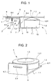
- the 1 shows a fastening device 2 which supports a car camera 1 and which is mounted on the outside of the cabin 3, for example on a car wall 4 of an elevator car 5 is arranged.
- the fastening device 2 can also be arranged on the outside of the cabin ceiling.
- the fastening device 2 consists of a first bracket 6, on which the camera 1 is arranged.
- the first bracket 6 is supported by a second bracket 7, which is arranged on a base plate 8.
- the cabin wall 4 is provided with at least one opening 9, through which the camera 1 can take an insight into the elevator car 5.
- Fig. 2 shows the first bracket 6 to which the camera 1 is attached to the long leg 6.1 of the bracket by means of screws 10.
- the long leg 6.1 has an opening 6.2 through which a cable 1.1 of the camera 1 is guided.
- a short leg of the bracket 6 is denoted by 6.3 and has a slot 6.4, which serves the attachment by means of at least one screw 11 on the second bracket 7.
- the camera 1 is arranged in a housing 1.2, wherein a housing ring 1.21 holds the camera 1.
- the lens of the camera 1 is designated, wherein the lens is 1.3 einjustierbar by means of the fastening device 2 on the opening 9.
- Fig. 3 shows the second leg 7 consisting of a short leg 7.1 with slot 7.2 and a long leg 7.3 with slot 7.4.
- the short leg 7.1 is connected by means of the screw 11 with the short leg 6.3 of the first bracket 6.
- Fig. 4 shows the base plate 8 with a threaded bolt 8.1, which fits into the slot 7.4 of the second bracket 7, wherein a nut 8.2 and a washer 8.3 a releasable connection between the base plate 8 and the second bracket 7 produces.
- the base plate 8 is provided with a double-sided adhesive film 8.4, the base plate 8 with the Cabin wall 4 connects.
- the adhesive film 8.4 may also be provided a screw or a rivet connection.
- Fig. 5 shows a section through the housing 1.2 and the housing ring 1.21, which holds the camera 1 in the housing 1.2, wherein the housing ring 1.21 can be screwed onto the housing 1.2.
- An internal thread 1.22 of the housing ring 1.21 fits on an external thread 1.23 of the housing 1.2.
- a ball joint which carries the camera 1, can be arranged on the first bracket 6.
Landscapes
- Fittings On The Vehicle Exterior For Carrying Loads, And Devices For Holding Or Mounting Articles (AREA)
- Closed-Circuit Television Systems (AREA)
- Cage And Drive Apparatuses For Elevators (AREA)
- Traffic Control Systems (AREA)
Abstract
Description
Die Erfindung betrifft eine Einrichtung zur Befestigung einer Kabinenkamera mittels der das Innere einer Aufzugskabine überwachbar ist, wobei die Kabinenkamera an einer der Kabinenwände oder an der Kabinendecke angeordnet ist.The invention relates to a device for fastening a car camera by means of which the interior of an elevator car can be monitored, wherein the car camera is arranged on one of the car walls or on the car ceiling.
Aus der Schrift JP 06064857 ist eine Aufzugskabine bekannt geworden, an der dachseitig zwei Überwachungskameras angeordnet sind. Die eine Kamera überwacht den Türbereich ab, die andere Kamera überwacht das Innere der Aufzugskabine. Eine Steuerung schaltet bei offener Tür die eine Kamera ein und schaltet bei geschlossener Tür die andere Kamera ein.From the document JP 06064857 an elevator car has become known, on the roof side two surveillance cameras are arranged. One camera monitors the door area, the other camera monitors the interior of the elevator car. One controller switches on one camera with the door open and switches on the other camera when the door is closed.
Ein weiteres Überwachungssystem is aus US-A-4 044 860 bekannt.Another monitoring system is known from US-A-4 044 860.
Ein Nachteil der bekannten Einrichtung liegt darin, dass zur Überwachung des Kabineninnerns zwei Kameras notwendig sind, was kostspielig ist und zudem eine teure Steuerung notwendig macht.A disadvantage of the known device is that two cameras are necessary for monitoring the cabin interior, which is costly and also makes expensive control necessary.
Hier will die Erfindung Abhilfe schaffen. Die Erfindung, wie sie in Anspruch 1 gekennzeichnet ist, löst die Aufgabe, die Nachteile der bekannten Einrichtung zu vermeiden und eine Aufzugskabine mit einer einfachen Überwachungseinrichtung vorzuschlagen.The invention aims to remedy this situation. The invention, as characterized in
Vorteilhafte Weiterbildungen der Erfindung sind in den abhängigen Patentansprüchen angegeben.Advantageous developments of the invention are specified in the dependent claims.
Die durch die Erfindung erreichten Vorteile sind im wesentlichen darin zu sehen, dass die ausserhalb der Aufzugskabine angeordnete Überwachungskamera einfach in alle Lagen ausgerichtet werden kann. Mit nur einer Überwachungskamera und einer immer gleichen Befestigungseinrichtung können Aufzugskabinen mit unterschiedlichen Grundrissen und unterschiedlichen Grössen überwacht werden.The advantages achieved by the invention are essentially to be seen in the fact that the surveillance camera arranged outside the elevator car can be easily aligned in all positions. With only one surveillance camera and a fixture that is always the same, lift cabins with different layouts and different sizes can be monitored.
Anhand der beiliegenden Figuren wird die vorliegende Erfindung näher erläutert.Reference to the accompanying figures, the present invention will be explained in more detail.
Es zeigen:
- Fig. 1
eine Befestigungseinrichtung für eine Kamera, - Fig. 2
einen ersten Befestigungsbügel mit der Kamera, - Fig. 3
einen zweiten Befestigungsbügel, - Fig. 4
eine Grundplatte und - Fig. 5
Einzelheiten eines Gehäuses für die Kamera.
- Fig. 1
a fastening device for a camera, - Fig. 2
a first mounting bracket with the camera, - Fig. 3
a second mounting bracket, - Fig. 4
a base plate and - Fig. 5
Details of a housing for the camera.
Fig. 1 zeigt eine eine Kabinenkamera 1 tragende Befestigungseinrichtung 2, die an der Kabinenaussenseite 3 beispielsweise an einer Kabinenwand 4 einer Aufzugskabine 5 angeordnet ist. Die Befestigungseinrichtung 2 kann auch an der Aussenseite der Kabinendecke angeordnet sein. Die Befestigungseinrichtung 2 besteht aus einem ersten Bügel 6, an dem die Kamera 1 angeordnet ist. Der erste Bügel 6 wird getragen von einem zweiten Bügel 7, der an einer Grundplatte 8 angeordnet ist. Die Kabinenwand 4 ist mit mindestens einer Öffnung 9 versehen, durch die die Kamera 1 Einsicht in die Aufzugskabine 5 nehmen kann.1 shows a
Fig. 2 zeigt den ersten Bügel 6 an dem die Kamera 1 am langen Schenkel 6.1 des Bügels mittels Schrauben 10 befestigt ist. Der lange Schenkel 6.1 weist eine Öffnung 6.2 auf, durch die ein Kabel 1.1 der Kamera 1 geführt ist. Ein kurzer Schenkel des Bügels 6 ist mit 6.3 bezeichnet und weist ein Langloch 6.4 auf, das der Befestigung mittels mindestens einer Schraube 11 am zweiten Bügel 7 dient. Die Kamera 1 ist in einem Gehäuse 1.2 angeordnet, wobei ein Gehäusering 1.21 die Kamera 1 festhält. Mit 1.3 ist die Linse der Kamera 1 bezeichnet, wobei die Linse 1.3 mittels der Befestigungseinrichtung 2 auf die Öffnung 9 einjustierbar ist.Fig. 2 shows the
Fig. 3 zeigt den zweiten Schenkel 7 bestehend aus einem kurzen Schenkel 7.1 mit Langloch 7.2 und einem langen Schenkel 7.3 mit Langloch 7.4. Der kurze Schenkel 7.1 ist mittels der Schraube 11 mit dem kurzen Schenkel 6.3 des ersten Bügels 6 verbunden.Fig. 3 shows the
Fig. 4 zeigt die Grundplatte 8 mit einem Gewindebolzen 8.1, der in das Langloch 7.4 des zweiten Bügels 7 passt, wobei eine Mutter 8.2 und eine Unterlagsscheibe 8.3 eine lösbare Verbindung zwischen der Grundplatte 8 und dem zweiten Bügel 7 herstellt. Die Grundplatte 8 ist mit einer zweiseitigen Klebefolie 8.4 versehen, die die Grundplatte 8 mit der Kabinenwand 4 verbindet. Anstelle der Klebefolie 8.4 kann auch eine Schraubverbindung oder eine Nietverbindung vorgesehen sein.Fig. 4 shows the
Fig. 5 zeigt einen Schnitt durch das Gehäuse 1.2 und den Gehäusering 1.21, der die Kamera 1 im Gehäuse 1.2 festhält, wobei der Gehäusering 1.21 auf das Gehäuse 1.2 aufschraubbar ist. Ein Innengewinde 1.22 des Gehäuserings 1.21 passt auf ein Aussengewinde 1.23 des Gehäuses 1.2.Fig. 5 shows a section through the housing 1.2 and the housing ring 1.21, which holds the
In einer weiteren Ausführungsvariante kann am ersten Bügel 6 ein Kugelgelenk angeordnet sein, das die Kamera 1 trägt.In a further embodiment variant, a ball joint, which carries the
Claims (7)
- Equipment for fixing a cage camera (1), by means of which the interior of a lift cage (5) can be monitored, wherein the cage camera (1) is arranged at one of the cage walls (4) or at the cage ceiling, characterised in that the cage camera (1) is arranged at a fastening device (2), by means of which a lens (1.3) of the cage camera (1) can be adjusted onto an opening (9) of the cage wall (4) or the cage ceiling, through which opening (9) the cage camera (1) can have a view into the lift cage (5).
- Equipment according to claim 1, characterised in that the fastening device (2) comprises several support elements (6, 7, 8), which are displaceable relative to one another.
- Equipment according to claim 2, characterised in that a first bracket (6) at which the cage camera (1) is arranged is provided, wherein the first bracket (6) is arranged to be displaceable at a second bracket (7) and the second bracket (7) is arranged to be displaceable at a base plate (8), which is connected with the cage wall (4) or with the cage ceiling.
- Equipment according to claim 3, characterised in that the brackets (6, 7) have slots (6.4. 7.2, 7.4), by means of which the brackets (6, 7) are displaceable.
- Equipment according to one of the preceding claims, characterised in that a ball joint carrying the cage camera (1) is arranged at the first bracket (6).
- Equipment according to one of the preceding claims, characterised in that the cage camera (1) is arranged in a housing (1.2) carried by the first bracket (6), wherein a housing ring (1.21) fixes the cage camera (1).
- Method of modernising a lift cage, characterised in that a camera (1) is arranged at one of the cage walls or at the cage ceiling, wherein the camera (1) is carried by a fastening device (2), by means of which a lens (1.3) of the camera (1) can be adjusted onto an opening (9) of the cage wall (4) or the cage ceiling, through which opening (9) the camera (1) can have a view into the lift cage (5).
Priority Applications (1)
| Application Number | Priority Date | Filing Date | Title |
|---|---|---|---|
| EP05002457A EP1574468B1 (en) | 2004-02-16 | 2005-02-05 | Arrangement for a surveillance camera on an elevator cabin |
Applications Claiming Priority (3)
| Application Number | Priority Date | Filing Date | Title |
|---|---|---|---|
| EP04405084 | 2004-02-16 | ||
| EP04405084 | 2004-02-16 | ||
| EP05002457A EP1574468B1 (en) | 2004-02-16 | 2005-02-05 | Arrangement for a surveillance camera on an elevator cabin |
Publications (2)
| Publication Number | Publication Date |
|---|---|
| EP1574468A1 EP1574468A1 (en) | 2005-09-14 |
| EP1574468B1 true EP1574468B1 (en) | 2006-11-08 |
Family
ID=34932042
Family Applications (1)
| Application Number | Title | Priority Date | Filing Date |
|---|---|---|---|
| EP05002457A Expired - Lifetime EP1574468B1 (en) | 2004-02-16 | 2005-02-05 | Arrangement for a surveillance camera on an elevator cabin |
Country Status (5)
| Country | Link |
|---|---|
| EP (1) | EP1574468B1 (en) |
| AT (1) | ATE344777T1 (en) |
| DE (1) | DE502005000166D1 (en) |
| DK (1) | DK1574468T3 (en) |
| ES (1) | ES2276356T3 (en) |
Cited By (1)
| Publication number | Priority date | Publication date | Assignee | Title |
|---|---|---|---|---|
| US11180344B2 (en) | 2017-05-23 | 2021-11-23 | Otis Elevator Company | Elevator doorway display systems for elevator cars |
Family Cites Families (4)
| Publication number | Priority date | Publication date | Assignee | Title |
|---|---|---|---|---|
| JPS5197155A (en) * | 1975-02-21 | 1976-08-26 | Erebeetano jokyakudeetashushusochi | |
| JPH0664857A (en) * | 1992-08-19 | 1994-03-08 | Hitachi Building Syst Eng & Service Co Ltd | Elevator security equipment |
| US6050369A (en) * | 1994-10-07 | 2000-04-18 | Toc Holding Company Of New York, Inc. | Elevator shaftway intrusion device using optical imaging processing |
| FR2829755B1 (en) * | 2001-09-18 | 2004-01-23 | Autinor | METHOD FOR MONITORING AN ELEVATOR CAB |
-
2005
- 2005-02-05 DK DK05002457T patent/DK1574468T3/en active
- 2005-02-05 DE DE502005000166T patent/DE502005000166D1/en not_active Expired - Lifetime
- 2005-02-05 EP EP05002457A patent/EP1574468B1/en not_active Expired - Lifetime
- 2005-02-05 AT AT05002457T patent/ATE344777T1/en active
- 2005-02-05 ES ES05002457T patent/ES2276356T3/en not_active Expired - Lifetime
Cited By (1)
| Publication number | Priority date | Publication date | Assignee | Title |
|---|---|---|---|---|
| US11180344B2 (en) | 2017-05-23 | 2021-11-23 | Otis Elevator Company | Elevator doorway display systems for elevator cars |
Also Published As
| Publication number | Publication date |
|---|---|
| DK1574468T3 (en) | 2007-02-12 |
| DE502005000166D1 (en) | 2006-12-21 |
| EP1574468A1 (en) | 2005-09-14 |
| ES2276356T3 (en) | 2007-06-16 |
| ATE344777T1 (en) | 2006-11-15 |
Similar Documents
| Publication | Publication Date | Title |
|---|---|---|
| EP2217469B1 (en) | Adjustment element | |
| DE102006039292B4 (en) | Frame element, aircraft air conditioning system and method for mounting a frame member in an aircraft | |
| DE102007036670B4 (en) | Kit for building a floor for a rail vehicle | |
| DE10353376A1 (en) | Device and method for the mechanical connection of two components | |
| DE60106194T2 (en) | SERVICE DEVICE | |
| DE102008003088A1 (en) | X-ray device comprising a C-arm, on which a radiation source is arranged together with heat pump | |
| EP1574468B1 (en) | Arrangement for a surveillance camera on an elevator cabin | |
| DE102006039290A1 (en) | Frame element for aircraft component assembly system, has connecting struts that are provided with recesses for receiving ribs of aircraft structure when frame element is attached to aircraft structure | |
| WO2021052679A1 (en) | Lighting device for a motor vehicle headlight | |
| DE4011909A1 (en) | Car door hinge with ball joints - has lower hinge strap with cylindrical bearing bush with coaxial hinge pin | |
| DE19919256A1 (en) | Bracket for a headlight of a vehicle | |
| EP2058910A2 (en) | Supply device | |
| DE10104311C1 (en) | compounding | |
| EP1313929A1 (en) | Door fastening | |
| DE20107806U1 (en) | point fixing | |
| EP0723380B1 (en) | Electronic information device, particularly emergency column | |
| DE10306921B3 (en) | Shower door fitting has frame and door-leaf band parts, holder for a band-pin, holder, thrust bearing, fixture section, screw for threaded hole and securing pin and hole | |
| EP2455568B1 (en) | Hinge with assembly aid for installing shower partitions | |
| EP3836365A1 (en) | Actuator | |
| DE202017004978U1 (en) | Tolerance compensation system | |
| DE102016008639A1 (en) | Fastening device for fastening at least one control device to a body of a vehicle | |
| DE102017202973B4 (en) | Adapter plate for attaching a switchgear housing to a profile | |
| EP4108877A1 (en) | Hinge for a door, window or similar component | |
| DE19913379A1 (en) | Carrier arrangement | |
| DE2913938A1 (en) | FASTENING DEVICE FOR A HOUSING LOCKING PART, IN PARTICULAR FOR SWITCHBOXES WITH ELECTRICAL SWITCHING DEVICES |
Legal Events
| Date | Code | Title | Description |
|---|---|---|---|
| PUAI | Public reference made under article 153(3) epc to a published international application that has entered the european phase |
Free format text: ORIGINAL CODE: 0009012 |
|
| AK | Designated contracting states |
Kind code of ref document: A1 Designated state(s): AT BE BG CH CY CZ DE DK EE ES FI FR GB GR HU IE IS IT LI LT LU MC NL PL PT RO SE SI SK TR |
|
| AX | Request for extension of the european patent |
Extension state: AL BA HR LV MK YU |
|
| 17P | Request for examination filed |
Effective date: 20060227 |
|
| GRAP | Despatch of communication of intention to grant a patent |
Free format text: ORIGINAL CODE: EPIDOSNIGR1 |
|
| AKX | Designation fees paid |
Designated state(s): AT BE BG CH CY CZ DE DK EE ES FI FR GB GR HU IE IS IT LI LT LU MC NL PL PT RO SE SI SK TR |
|
| RTI1 | Title (correction) |
Free format text: ARRANGEMENT FOR A SURVEILLANCE CAMERA ON AN ELEVATOR CABIN |
|
| GRAS | Grant fee paid |
Free format text: ORIGINAL CODE: EPIDOSNIGR3 |
|
| GRAA | (expected) grant |
Free format text: ORIGINAL CODE: 0009210 |
|
| AK | Designated contracting states |
Kind code of ref document: B1 Designated state(s): AT BE BG CH CY CZ DE DK EE ES FI FR GB GR HU IE IS IT LI LT LU MC NL PL PT RO SE SI SK TR |
|
| PG25 | Lapsed in a contracting state [announced via postgrant information from national office to epo] |
Ref country code: RO Free format text: LAPSE BECAUSE OF FAILURE TO SUBMIT A TRANSLATION OF THE DESCRIPTION OR TO PAY THE FEE WITHIN THE PRESCRIBED TIME-LIMIT Effective date: 20061108 Ref country code: PL Free format text: LAPSE BECAUSE OF FAILURE TO SUBMIT A TRANSLATION OF THE DESCRIPTION OR TO PAY THE FEE WITHIN THE PRESCRIBED TIME-LIMIT Effective date: 20061108 Ref country code: CZ Free format text: LAPSE BECAUSE OF FAILURE TO SUBMIT A TRANSLATION OF THE DESCRIPTION OR TO PAY THE FEE WITHIN THE PRESCRIBED TIME-LIMIT Effective date: 20061108 Ref country code: SI Free format text: LAPSE BECAUSE OF FAILURE TO SUBMIT A TRANSLATION OF THE DESCRIPTION OR TO PAY THE FEE WITHIN THE PRESCRIBED TIME-LIMIT Effective date: 20061108 Ref country code: SK Free format text: LAPSE BECAUSE OF FAILURE TO SUBMIT A TRANSLATION OF THE DESCRIPTION OR TO PAY THE FEE WITHIN THE PRESCRIBED TIME-LIMIT Effective date: 20061108 |
|
| REG | Reference to a national code |
Ref country code: GB Ref legal event code: FG4D Free format text: NOT ENGLISH |
|
| REG | Reference to a national code |
Ref country code: CH Ref legal event code: EP |
|
| REG | Reference to a national code |
Ref country code: IE Ref legal event code: FG4D Free format text: LANGUAGE OF EP DOCUMENT: GERMAN |
|
| REF | Corresponds to: |
Ref document number: 502005000166 Country of ref document: DE Date of ref document: 20061221 Kind code of ref document: P |
|
| GBT | Gb: translation of ep patent filed (gb section 77(6)(a)/1977) |
Effective date: 20070110 |
|
| PG25 | Lapsed in a contracting state [announced via postgrant information from national office to epo] |
Ref country code: BG Free format text: LAPSE BECAUSE OF FAILURE TO SUBMIT A TRANSLATION OF THE DESCRIPTION OR TO PAY THE FEE WITHIN THE PRESCRIBED TIME-LIMIT Effective date: 20070208 |
|
| REG | Reference to a national code |
Ref country code: DK Ref legal event code: T3 |
|
| REG | Reference to a national code |
Ref country code: SE Ref legal event code: TRGR |
|
| PG25 | Lapsed in a contracting state [announced via postgrant information from national office to epo] |
Ref country code: IS Free format text: LAPSE BECAUSE OF FAILURE TO SUBMIT A TRANSLATION OF THE DESCRIPTION OR TO PAY THE FEE WITHIN THE PRESCRIBED TIME-LIMIT Effective date: 20070308 |
|
| ET | Fr: translation filed | ||
| PG25 | Lapsed in a contracting state [announced via postgrant information from national office to epo] |
Ref country code: PT Free format text: LAPSE BECAUSE OF FAILURE TO SUBMIT A TRANSLATION OF THE DESCRIPTION OR TO PAY THE FEE WITHIN THE PRESCRIBED TIME-LIMIT Effective date: 20070409 |
|
| REG | Reference to a national code |
Ref country code: ES Ref legal event code: FG2A Ref document number: 2276356 Country of ref document: ES Kind code of ref document: T3 |
|
| PLBE | No opposition filed within time limit |
Free format text: ORIGINAL CODE: 0009261 |
|
| STAA | Information on the status of an ep patent application or granted ep patent |
Free format text: STATUS: NO OPPOSITION FILED WITHIN TIME LIMIT |
|
| 26N | No opposition filed |
Effective date: 20070809 |
|
| PG25 | Lapsed in a contracting state [announced via postgrant information from national office to epo] |
Ref country code: GR Free format text: LAPSE BECAUSE OF FAILURE TO SUBMIT A TRANSLATION OF THE DESCRIPTION OR TO PAY THE FEE WITHIN THE PRESCRIBED TIME-LIMIT Effective date: 20070209 |
|
| PG25 | Lapsed in a contracting state [announced via postgrant information from national office to epo] |
Ref country code: LT Free format text: LAPSE BECAUSE OF FAILURE TO SUBMIT A TRANSLATION OF THE DESCRIPTION OR TO PAY THE FEE WITHIN THE PRESCRIBED TIME-LIMIT Effective date: 20061108 |
|
| PG25 | Lapsed in a contracting state [announced via postgrant information from national office to epo] |
Ref country code: EE Free format text: LAPSE BECAUSE OF FAILURE TO SUBMIT A TRANSLATION OF THE DESCRIPTION OR TO PAY THE FEE WITHIN THE PRESCRIBED TIME-LIMIT Effective date: 20061108 |
|
| PG25 | Lapsed in a contracting state [announced via postgrant information from national office to epo] |
Ref country code: CY Free format text: LAPSE BECAUSE OF FAILURE TO SUBMIT A TRANSLATION OF THE DESCRIPTION OR TO PAY THE FEE WITHIN THE PRESCRIBED TIME-LIMIT Effective date: 20061108 |
|
| PG25 | Lapsed in a contracting state [announced via postgrant information from national office to epo] |
Ref country code: HU Free format text: LAPSE BECAUSE OF FAILURE TO SUBMIT A TRANSLATION OF THE DESCRIPTION OR TO PAY THE FEE WITHIN THE PRESCRIBED TIME-LIMIT Effective date: 20070509 Ref country code: TR Free format text: LAPSE BECAUSE OF FAILURE TO SUBMIT A TRANSLATION OF THE DESCRIPTION OR TO PAY THE FEE WITHIN THE PRESCRIBED TIME-LIMIT Effective date: 20061108 |
|
| PGFP | Annual fee paid to national office [announced via postgrant information from national office to epo] |
Ref country code: LU Payment date: 20120222 Year of fee payment: 8 |
|
| PGFP | Annual fee paid to national office [announced via postgrant information from national office to epo] |
Ref country code: MC Payment date: 20120213 Year of fee payment: 8 Ref country code: IE Payment date: 20120217 Year of fee payment: 8 Ref country code: FR Payment date: 20120227 Year of fee payment: 8 |
|
| PGFP | Annual fee paid to national office [announced via postgrant information from national office to epo] |
Ref country code: BE Payment date: 20120329 Year of fee payment: 8 Ref country code: DK Payment date: 20120217 Year of fee payment: 8 Ref country code: IT Payment date: 20120221 Year of fee payment: 8 Ref country code: SE Payment date: 20120217 Year of fee payment: 8 |
|
| PGFP | Annual fee paid to national office [announced via postgrant information from national office to epo] |
Ref country code: AT Payment date: 20120213 Year of fee payment: 8 |
|
| PGFP | Annual fee paid to national office [announced via postgrant information from national office to epo] |
Ref country code: ES Payment date: 20120224 Year of fee payment: 8 |
|
| BERE | Be: lapsed |
Owner name: INVENTIO A.G. Effective date: 20130228 |
|
| REG | Reference to a national code |
Ref country code: DK Ref legal event code: EBP |
|
| PG25 | Lapsed in a contracting state [announced via postgrant information from national office to epo] |
Ref country code: MC Free format text: LAPSE BECAUSE OF NON-PAYMENT OF DUE FEES Effective date: 20130228 |
|
| REG | Reference to a national code |
Ref country code: SE Ref legal event code: EUG |
|
| REG | Reference to a national code |
Ref country code: AT Ref legal event code: MM01 Ref document number: 344777 Country of ref document: AT Kind code of ref document: T Effective date: 20130228 |
|
| PG25 | Lapsed in a contracting state [announced via postgrant information from national office to epo] |
Ref country code: AT Free format text: LAPSE BECAUSE OF NON-PAYMENT OF DUE FEES Effective date: 20130228 Ref country code: SE Free format text: LAPSE BECAUSE OF NON-PAYMENT OF DUE FEES Effective date: 20130206 |
|
| REG | Reference to a national code |
Ref country code: FR Ref legal event code: ST Effective date: 20131031 |
|
| REG | Reference to a national code |
Ref country code: IE Ref legal event code: MM4A |
|
| PG25 | Lapsed in a contracting state [announced via postgrant information from national office to epo] |
Ref country code: IT Free format text: LAPSE BECAUSE OF NON-PAYMENT OF DUE FEES Effective date: 20130205 |
|
| PG25 | Lapsed in a contracting state [announced via postgrant information from national office to epo] |
Ref country code: DK Free format text: LAPSE BECAUSE OF NON-PAYMENT OF DUE FEES Effective date: 20130228 Ref country code: IE Free format text: LAPSE BECAUSE OF NON-PAYMENT OF DUE FEES Effective date: 20130205 Ref country code: FR Free format text: LAPSE BECAUSE OF NON-PAYMENT OF DUE FEES Effective date: 20130228 Ref country code: BE Free format text: LAPSE BECAUSE OF NON-PAYMENT OF DUE FEES Effective date: 20130228 |
|
| REG | Reference to a national code |
Ref country code: ES Ref legal event code: FD2A Effective date: 20140409 |
|
| PG25 | Lapsed in a contracting state [announced via postgrant information from national office to epo] |
Ref country code: ES Free format text: LAPSE BECAUSE OF NON-PAYMENT OF DUE FEES Effective date: 20130206 |
|
| PG25 | Lapsed in a contracting state [announced via postgrant information from national office to epo] |
Ref country code: LU Free format text: LAPSE BECAUSE OF NON-PAYMENT OF DUE FEES Effective date: 20130205 |
|
| PGFP | Annual fee paid to national office [announced via postgrant information from national office to epo] |
Ref country code: NL Payment date: 20180216 Year of fee payment: 14 |
|
| PGFP | Annual fee paid to national office [announced via postgrant information from national office to epo] |
Ref country code: DE Payment date: 20180219 Year of fee payment: 14 Ref country code: FI Payment date: 20180219 Year of fee payment: 14 Ref country code: GB Payment date: 20180216 Year of fee payment: 14 Ref country code: CH Payment date: 20180216 Year of fee payment: 14 |
|
| REG | Reference to a national code |
Ref country code: DE Ref legal event code: R119 Ref document number: 502005000166 Country of ref document: DE |
|
| REG | Reference to a national code |
Ref country code: CH Ref legal event code: PL |
|
| REG | Reference to a national code |
Ref country code: NL Ref legal event code: MM Effective date: 20190301 |
|
| GBPC | Gb: european patent ceased through non-payment of renewal fee |
Effective date: 20190205 |
|
| PG25 | Lapsed in a contracting state [announced via postgrant information from national office to epo] |
Ref country code: FI Free format text: LAPSE BECAUSE OF NON-PAYMENT OF DUE FEES Effective date: 20190205 |
|
| PG25 | Lapsed in a contracting state [announced via postgrant information from national office to epo] |
Ref country code: CH Free format text: LAPSE BECAUSE OF NON-PAYMENT OF DUE FEES Effective date: 20190228 Ref country code: LI Free format text: LAPSE BECAUSE OF NON-PAYMENT OF DUE FEES Effective date: 20190228 |
|
| PG25 | Lapsed in a contracting state [announced via postgrant information from national office to epo] |
Ref country code: DE Free format text: LAPSE BECAUSE OF NON-PAYMENT OF DUE FEES Effective date: 20190903 Ref country code: GB Free format text: LAPSE BECAUSE OF NON-PAYMENT OF DUE FEES Effective date: 20190205 Ref country code: NL Free format text: LAPSE BECAUSE OF NON-PAYMENT OF DUE FEES Effective date: 20190301 |