EP1574425A2 - A motor unit for a ship - Google Patents
A motor unit for a ship Download PDFInfo
- Publication number
- EP1574425A2 EP1574425A2 EP05105483A EP05105483A EP1574425A2 EP 1574425 A2 EP1574425 A2 EP 1574425A2 EP 05105483 A EP05105483 A EP 05105483A EP 05105483 A EP05105483 A EP 05105483A EP 1574425 A2 EP1574425 A2 EP 1574425A2
- Authority
- EP
- European Patent Office
- Prior art keywords
- motor
- unit
- assembly
- motor unit
- arrangement according
- Prior art date
- Legal status (The legal status is an assumption and is not a legal conclusion. Google has not performed a legal analysis and makes no representation as to the accuracy of the status listed.)
- Granted
Links
- 238000001816 cooling Methods 0.000 claims abstract description 23
- XLYOFNOQVPJJNP-UHFFFAOYSA-N water Substances O XLYOFNOQVPJJNP-UHFFFAOYSA-N 0.000 claims abstract description 16
- 230000015572 biosynthetic process Effects 0.000 claims description 2
- 238000005755 formation reaction Methods 0.000 claims description 2
- 238000012423 maintenance Methods 0.000 description 4
- 238000005516 engineering process Methods 0.000 description 3
- 238000004519 manufacturing process Methods 0.000 description 3
- 238000002485 combustion reaction Methods 0.000 description 2
- 230000002349 favourable effect Effects 0.000 description 2
- 230000000712 assembly Effects 0.000 description 1
- 238000000429 assembly Methods 0.000 description 1
- 230000004323 axial length Effects 0.000 description 1
- 238000006243 chemical reaction Methods 0.000 description 1
- 239000002826 coolant Substances 0.000 description 1
- 238000009434 installation Methods 0.000 description 1
- 239000007788 liquid Substances 0.000 description 1
- 238000005461 lubrication Methods 0.000 description 1
- 238000012806 monitoring device Methods 0.000 description 1
- 238000005086 pumping Methods 0.000 description 1
- 230000005477 standard model Effects 0.000 description 1
- 230000007306 turnover Effects 0.000 description 1
Images


Classifications
-
- B—PERFORMING OPERATIONS; TRANSPORTING
- B63—SHIPS OR OTHER WATERBORNE VESSELS; RELATED EQUIPMENT
- B63H—MARINE PROPULSION OR STEERING
- B63H1/00—Propulsive elements directly acting on water
- B63H1/02—Propulsive elements directly acting on water of rotary type
- B63H1/12—Propulsive elements directly acting on water of rotary type with rotation axis substantially in propulsive direction
- B63H1/14—Propellers
- B63H1/28—Other means for improving propeller efficiency
-
- B—PERFORMING OPERATIONS; TRANSPORTING
- B63—SHIPS OR OTHER WATERBORNE VESSELS; RELATED EQUIPMENT
- B63J—AUXILIARIES ON VESSELS
- B63J2/00—Arrangements of ventilation, heating, cooling, or air-conditioning
- B63J2/12—Heating; Cooling
-
- B—PERFORMING OPERATIONS; TRANSPORTING
- B63—SHIPS OR OTHER WATERBORNE VESSELS; RELATED EQUIPMENT
- B63H—MARINE PROPULSION OR STEERING
- B63H23/00—Transmitting power from propulsion power plant to propulsive elements
- B63H23/22—Transmitting power from propulsion power plant to propulsive elements with non-mechanical gearing
- B63H23/24—Transmitting power from propulsion power plant to propulsive elements with non-mechanical gearing electric
-
- B—PERFORMING OPERATIONS; TRANSPORTING
- B63—SHIPS OR OTHER WATERBORNE VESSELS; RELATED EQUIPMENT
- B63H—MARINE PROPULSION OR STEERING
- B63H5/00—Arrangements on vessels of propulsion elements directly acting on water
- B63H5/07—Arrangements on vessels of propulsion elements directly acting on water of propellers
- B63H5/125—Arrangements on vessels of propulsion elements directly acting on water of propellers movably mounted with respect to hull, e.g. adjustable in direction, e.g. podded azimuthing thrusters
- B63H2005/1254—Podded azimuthing thrusters, i.e. podded thruster units arranged inboard for rotation about vertical axis
- B63H2005/1258—Podded azimuthing thrusters, i.e. podded thruster units arranged inboard for rotation about vertical axis with electric power transmission to propellers, i.e. with integrated electric propeller motors
-
- B—PERFORMING OPERATIONS; TRANSPORTING
- B63—SHIPS OR OTHER WATERBORNE VESSELS; RELATED EQUIPMENT
- B63H—MARINE PROPULSION OR STEERING
- B63H5/00—Arrangements on vessels of propulsion elements directly acting on water
- B63H5/07—Arrangements on vessels of propulsion elements directly acting on water of propellers
-
- Y—GENERAL TAGGING OF NEW TECHNOLOGICAL DEVELOPMENTS; GENERAL TAGGING OF CROSS-SECTIONAL TECHNOLOGIES SPANNING OVER SEVERAL SECTIONS OF THE IPC; TECHNICAL SUBJECTS COVERED BY FORMER USPC CROSS-REFERENCE ART COLLECTIONS [XRACs] AND DIGESTS
- Y02—TECHNOLOGIES OR APPLICATIONS FOR MITIGATION OR ADAPTATION AGAINST CLIMATE CHANGE
- Y02T—CLIMATE CHANGE MITIGATION TECHNOLOGIES RELATED TO TRANSPORTATION
- Y02T10/00—Road transport of goods or passengers
- Y02T10/60—Other road transportation technologies with climate change mitigation effect
- Y02T10/70—Energy storage systems for electromobility, e.g. batteries
Definitions
- the present invention relates to a propulsion unit arrangement for a ship, said arrangement including a motor unit located in the water, which motor unit includes an electric motor and control devices related thereto as well as a propeller arranged at the motor's shaft.
- a conventional motor arrangement in a ship comprises a motor arranged within the ship's hull and a propeller arranged on the end of a motor shaft which extends in a watertight manner through the ship's hull.
- Said motor can be a directly employed diesel engine or like combustion engine or, favorably, an electric motor to which necessary electric power is supplied by a conventional combustion engine, a gas turbine, a nuclear power plant or the like.
- the steering of such ships is conventionally being arranged so that a pivoting rudder is provided in the propeller's wake. said rudder deflecting the wake and thus creating a lateral force component in relation to the longitudinal direction of the ship.
- propulsion units wherein the propeller as such can be pivoted for the purpose of steering the ship.
- This pivoting motion can be accomplished by means of a rather complicated shaft arrangement, or in such a way that the propeller is arranged at the shaft of a motor which as such is arranged to be rotatable around a vertical axis.
- This latter arrangement is called an azimuthing propulsion device, and such a device is described in, for example, the applicant's Finnish patent No. 76977, which device is being marketed by the applicant under the trademark AZIPOD.
- an electric motor known per se is arranged in a motor housing, which is part of an assembly located outside the ship's hull proper.
- the assembly is rotatable in relation to the ship.
- a relatively powerful electric motor generates, in addition to the actual propeller power, a considerable amount of heat which has to be removed from the motor.
- the electric motor is then arranged to be air cooled, since air cooling has been found to be appropriate particularly with respect to reliability of operation and of maintenance. In such a case the cooling ducts in addition provide service access passage to the vicinity of the motor.
- air cooling is, however, the large space requirements of the arrangements.
- the present invention is characterized in that the motor unit comprises a casing structure which structurally and functionally constitutes a part of the motor so that the motor as such along a whole circumferential surface thereof is directly exposed to the water outside the motor unit, whereby the cooling of the electric motor is effected at said circumferential surface through said casing structure directly to the water outside the unit.
- the arrangement in practice includes such an electric motor for which an essential portion of the cooling takes place via the motor's whole circumferential surface directly to a medium located outside the unit, immediately through any possible casing structure which structurally and functionally is a part of the motor.
- the motor's structure as such additionally constitutes a casing
- the scope of the present invention includes such embodiments as well. Consequently, the arrangement according to the present invention thus appropriately comprises a motor, which as such is in direct contact with the water around the ship.
- the motor is not positioned within any special motor housing of any assembly associated with the ship, but the motor rather in itself constitutes a part of the casing of such a structure.
- a modular motor unit 1 generally comprises an electric motor 2 having a propeller 4 arranged at a motor shaft 3.
- an outer casing 5 for said motor unit is arranged so that the motor 2 as such is cooled by the surrounding water 6 directly through said casing 5 which is structurally associated with said motor.
- the motor's 2 shaft 3 is supported, in a manner known per se , at both ends of the motor by means of bearings 7 to which gaskets known per se suitably are arranged so that the interior 8 of the motor favorably is completely isolated from the surrounding water 6, and suitably also from the interior 10 of an attachment assembly 9.
- the motor unit is provided with fastening means which suitably are flanges 11, by means of which the motor unit can be attached to corresponding flange means 16, 16a, 16b arranged at said attachment assembly 9, or to means 16c arranged directly on the ship's hull 12 as disclosed in Fig. 3.
- Fig. 1 further discloses by means of a schematic reference 13 that connections to the motor 2, such as power supply, control and monitoring devices, any lubrication means etc. favorably are connected by means of a central connector to said attachment assembly 9 or to the ship's hull 12, respectively, which renders the attachment as efficient as possible.
- the motor unit can be given an extremely compact design it can be effectively cooled directly without using other cooling systems.
- the arrangement according to the invention enables attachment systems for the propulsion unit to be considerably slimmer than before, which provides a surface area and thus also, e.g., a frontal area meeting the water flow, which areas are smaller than known in prior art.
- omitting any separate cooling arrangements passing through the azimuthing assembly also implies that the portion of the assembly, which is attached to the ship 12, can be considerably smaller than earlier structures.
- the cooling arrangement according to the present invention results in a still more compact structure, since in most cases the cooling and the special arrangements used in present devices of this kind can be completely omitted. As a result, the production of the motor unit becomes easier and faster, and the weight of the unit remains small and thus, accordingly, the equipment needed for the production of the unit can be smaller as well.
- the motor unit 2 which as such contains even quite complicated technology, can be manufactured in long series with insignificant consideration of the end use. This also ensures, that the supply of spare parts for the motor unit can be very extensive, to start with having complete units as such available as goods in stock at the main shipyards or even carried on board the ship.
- the arrangement according to the present invention provides a significantly smaller cross section in the direction of the flow, as compared with present ones, whereby a better propulsion efficiency is achieved using a smaller propeller. Also, it is usually possible to use smaller bearings 7.
- the arrangement according to the present invention enables fast production and shorter stock turnover time.
- Maintenance is fast and simple due to inter-changeability and standard models, which is a significant advantage considering the fact, that ship lay days for maintenance or repair can become extremely expensive.
- the arrangement disclosed in Fig. 1 is functionally equivalent to the azimuthing propulsion system described above, i.e. the whole assembly 9 is rotatable around a vertical axis A-A.
- an assembly including a motor replaces the propeller-rudder assembly of the earlier technology, which in comparison to earlier technology provides i.a. clearly better efficiency and improved turning characteristics.
- the assembly 9 in the embodiment according to Fig. 1 favorably comprises an essentially hollow and suitably at least to some extent curved body portion which is attached by means of flanges to arrangements for turning, power supply, and control, known per se are known in the art, and which are referred to only indicatively by reference number 14. Due to the curved attachment assembly, the whole device pivots in an optimal way in a similar manner as known azimuthing propulsion devices.
- a modular structure implemented in accordance with the teaching of a co-pending further ensures that symmetry necessary for a balanced cooling particularly easily can be achieved. Due to the favorably modular embodiment the unit has no such external parts, which would cause any points of discontinuity in respect to cooling, but rather allows access everywhere for the surrounding water 6 to serve as a coolant.
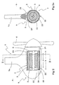
- Figures 2 and 2a disclose an alternative attachment arrangement, wherein the attachment assembly supporting the motor comprises an essentially vertical central body 9a with suitably circular portions 19, 20 supporting the motor unit 1. These portions 19, 20 preferably surround just a part of the motor unit 1 so that a clear opening 21 remains between the central portion of the motor unit 1 and the assembly 9.
- This opening which suitably extends at least over the axial length "a" of the rotor 22, favorably, however, at least also over the length "b" of the stator 23, renders it possible for the medium 6 outside the unit, usually water, to be in contact with the heat emitting portions of the motor at least at the longitudinally central portion of the motor 2, in particular with the whole circumference of the portion of the casing 5, which favorably is immediately adjacent to the stator.
- Fig. 2 comprises an arrangement wherein an annular portion 19 surrounds one end of the motor assembly 1, while an attachment portion 20 located at the opposite end alternatively also can be just an attachment flange arrangement 11, 16 similar to the one disclosed in Fig. 1.
- said annular portion 19 has been replaced by separate fasteners (not shown) and in another embodiment an annular portion 19 has been completely omitted.
- Fig. 3 again, discloses a solution where, instead of a conventional propeller assembly, a modular motor unit 1 according to the present invention is attached directly to the hull of a ship 12. A considerable part of the advantages offered by the modular structure and the direct cooling arrangement according to the present invention also can be achieved in this case.
Landscapes
- Engineering & Computer Science (AREA)
- Combustion & Propulsion (AREA)
- Mechanical Engineering (AREA)
- Ocean & Marine Engineering (AREA)
- Chemical & Material Sciences (AREA)
- Motor Or Generator Cooling System (AREA)
- Motor Or Generator Frames (AREA)
- Connection Of Motors, Electrical Generators, Mechanical Devices, And The Like (AREA)
- Automatic Cycles, And Cycles In General (AREA)
- Iron Core Of Rotating Electric Machines (AREA)
- Revetment (AREA)
- Lubrication Details And Ventilation Of Internal Combustion Engines (AREA)
- Control Of Throttle Valves Provided In The Intake System Or In The Exhaust System (AREA)
- Lens Barrels (AREA)
- Control Of Electric Motors In General (AREA)
Abstract
Description
- The present invention relates to a propulsion unit arrangement for a ship, said arrangement including a motor unit located in the water, which motor unit includes an electric motor and control devices related thereto as well as a propeller arranged at the motor's shaft.
- A conventional motor arrangement in a ship comprises a motor arranged within the ship's hull and a propeller arranged on the end of a motor shaft which extends in a watertight manner through the ship's hull. As the propeller rotates it brings water surrounding the ship into motion and thus creates a reaction force which thrusts the ship forwards. Said motor can be a directly employed diesel engine or like combustion engine or, favorably, an electric motor to which necessary electric power is supplied by a conventional combustion engine, a gas turbine, a nuclear power plant or the like. The steering of such ships is conventionally being arranged so that a pivoting rudder is provided in the propeller's wake. said rudder deflecting the wake and thus creating a lateral force component in relation to the longitudinal direction of the ship.
- Other types of so called propulsion units are also known, wherein the propeller as such can be pivoted for the purpose of steering the ship. This pivoting motion can be accomplished by means of a rather complicated shaft arrangement, or in such a way that the propeller is arranged at the shaft of a motor which as such is arranged to be rotatable around a vertical axis. This latter arrangement is called an azimuthing propulsion device, and such a device is described in, for example, the applicant's Finnish patent No. 76977, which device is being marketed by the applicant under the trademark AZIPOD.
- Usually, in the azimuthing propulsion devices of today an electric motor known per se is arranged in a motor housing, which is part of an assembly located outside the ship's hull proper. The assembly is rotatable in relation to the ship. However, a relatively powerful electric motor generates, in addition to the actual propeller power, a considerable amount of heat which has to be removed from the motor. Typically the electric motor is then arranged to be air cooled, since air cooling has been found to be appropriate particularly with respect to reliability of operation and of maintenance. In such a case the cooling ducts in addition provide service access passage to the vicinity of the motor. One of the disadvantages of air cooling is, however, the large space requirements of the arrangements. There also have been attempts to implement cooling arrangements operating with liquid, for instance, whereby the actual cooling device is located outside the propulsion unit, but in practice such a solution has proved rather complicated, considering that the azimuthing unit as such is adapted to be rotatable. Attempts further have been made to construct motors in such a way, that their cooling would take place via the outer casing of the motor housing surrounding the motor, but these solutions have not worked to satisfaction, and they have always required the use of motors based only on a certain particular working principle.
- In a co-pending patent application the design of the motor in itself is proposed to constitute an extremely compact modular unit, which at one end thereof can be attached to a ship and which the opposite end comprises propeller means. In that solution there is no actual motor housing, but the motor is attached as such to the ship or to an arm structure supported rotatably with respect to the ship. Particularly in connection with the azimuthing propulsion system mentioned above many significant advantages are achieved by using such a module arrangement. One such arrangement additionally enables a solution to the problem of cooling of the motor.
The characteristic features of the solution according to the present invention are presented in the accompanying claims. Thus, the present invention is characterized in that the motor unit comprises a casing structure which structurally and functionally constitutes a part of the motor so that the motor as such along a whole circumferential surface thereof is directly exposed to the water outside the motor unit, whereby the cooling of the electric motor is effected at said circumferential surface through said casing structure directly to the water outside the unit. - Thus, the arrangement in practice includes such an electric motor for which an essential portion of the cooling takes place via the motor's whole circumferential surface directly to a medium located outside the unit, immediately through any possible casing structure which structurally and functionally is a part of the motor. In some embodiments no clear casing structure can even be defined, in which case the motor's structure as such additionally constitutes a casing, and the scope of the present invention includes such embodiments as well. Consequently, the arrangement according to the present invention thus appropriately comprises a motor, which as such is in direct contact with the water around the ship. Thus, the motor is not positioned within any special motor housing of any assembly associated with the ship, but the motor rather in itself constitutes a part of the casing of such a structure.
- The present invention will now be presented in more detail with reference to some favorable embodiments and to the accompanying drawings, where
- Fig. 1
- as a schematic sectional view discloses an example of an embodiment of a motor arrangement according to the present invention in connection with an azimuthing propulsion system,
- Fig. 2
- partially in section discloses an alternative installation arrangement,
- Fig. 2a
- in a corresponding manner discloses a section at B-B in Fig. 2, and
- Fig. 3
- discloses a solution, wherein a motor unit according to the present invention is arranged as a rigid propulsion means in the stem of a ship, thus replacing a conventional propeller arrangement.
- Referring to Fig. 1 a
modular motor unit 1 according to the present invention generally comprises anelectric motor 2 having apropeller 4 arranged at amotor shaft 3. According to the present invention anouter casing 5 for said motor unit is arranged so that themotor 2 as such is cooled by the surroundingwater 6 directly through saidcasing 5 which is structurally associated with said motor. The motor's 2shaft 3 is supported, in a manner known per se, at both ends of the motor by means ofbearings 7 to which gaskets known per se suitably are arranged so that theinterior 8 of the motor favorably is completely isolated from the surroundingwater 6, and suitably also from theinterior 10 of anattachment assembly 9. - The motor unit is provided with fastening means which suitably are
flanges 11, by means of which the motor unit can be attached to corresponding flange means 16, 16a, 16b arranged at saidattachment assembly 9, or to means 16c arranged directly on the ship'shull 12 as disclosed in Fig. 3. Fig. 1 further discloses by means of aschematic reference 13 that connections to themotor 2, such as power supply, control and monitoring devices, any lubrication means etc. favorably are connected by means of a central connector to saidattachment assembly 9 or to the ship'shull 12, respectively, which renders the attachment as efficient as possible. - Many significant advantages are achieved by the general arrangement according to the present invention. Since the motor unit can be given an extremely compact design it can be effectively cooled directly without using other cooling systems. Thus, the arrangement according to the invention enables attachment systems for the propulsion unit to be considerably slimmer than before, which provides a surface area and thus also, e.g., a frontal area meeting the water flow, which areas are smaller than known in prior art. In practice, omitting any separate cooling arrangements passing through the azimuthing assembly also implies that the portion of the assembly, which is attached to the
ship 12, can be considerably smaller than earlier structures. The cooling arrangement according to the present invention results in a still more compact structure, since in most cases the cooling and the special arrangements used in present devices of this kind can be completely omitted. As a result, the production of the motor unit becomes easier and faster, and the weight of the unit remains small and thus, accordingly, the equipment needed for the production of the unit can be smaller as well. - Since it, to a wide extent, is a matter of a standardized assembly, which as such is applicable to a great number of different uses, the
motor unit 2, which as such contains even quite complicated technology, can be manufactured in long series with insignificant consideration of the end use. This also ensures, that the supply of spare parts for the motor unit can be very extensive, to start with having complete units as such available as goods in stock at the main shipyards or even carried on board the ship. - Due to its compact design, the arrangement according to the present invention provides a significantly smaller cross section in the direction of the flow, as compared with present ones, whereby a better propulsion efficiency is achieved using a smaller propeller. Also, it is usually possible to use
smaller bearings 7. - From the aspects of product delivery and maintenance, the arrangement according to the present invention enables fast production and shorter stock turnover time. Maintenance is fast and simple due to inter-changeability and standard models, which is a significant advantage considering the fact, that ship lay days for maintenance or repair can become extremely expensive.
- Preferably the arrangement disclosed in Fig. 1 is functionally equivalent to the azimuthing propulsion system described above, i.e. the
whole assembly 9 is rotatable around a vertical axis A-A. Thus, an assembly including a motor replaces the propeller-rudder assembly of the earlier technology, which in comparison to earlier technology provides i.a. clearly better efficiency and improved turning characteristics. Theassembly 9 in the embodiment according to Fig. 1 favorably comprises an essentially hollow and suitably at least to some extent curved body portion which is attached by means of flanges to arrangements for turning, power supply, and control, known per se are known in the art, and which are referred to only indicatively byreference number 14. Due to the curved attachment assembly, the whole device pivots in an optimal way in a similar manner as known azimuthing propulsion devices. - A modular structure implemented in accordance with the teaching of a co-pending further ensures that symmetry necessary for a balanced cooling particularly easily can be achieved. Due to the favorably modular embodiment the unit has no such external parts, which would cause any points of discontinuity in respect to cooling, but rather allows access everywhere for the surrounding
water 6 to serve as a coolant. - However, according to one embodiment further arrangements have been taken, if necessary, so that there is a heat conducting medium in the
motor 2 or at its most sensitive location, which medium can be set in motion, i necessary, by means of suitable pumping or the like means 17 in order to enhance the heat transfer. Additionally, the structures andspace 10 of the arm assembly supporting the motor unit can be utilized so that in particularly hot conditions additional cooling media can be circulated therein. In some embodiments themotor unit 1 in itself, as well as possibly also thearm assembly 9 supporting it, are provided withcooling fins 18 or similar formations which facilitate a heat transfer. - Figures 2 and 2a disclose an alternative attachment arrangement, wherein the attachment assembly supporting the motor comprises an essentially vertical
central body 9a with suitablycircular portions motor unit 1. Theseportions motor unit 1 so that aclear opening 21 remains between the central portion of themotor unit 1 and theassembly 9. This opening, which suitably extends at least over the axial length "a" of therotor 22, favorably, however, at least also over the length "b" of thestator 23, renders it possible for themedium 6 outside the unit, usually water, to be in contact with the heat emitting portions of the motor at least at the longitudinally central portion of themotor 2, in particular with the whole circumference of the portion of thecasing 5, which favorably is immediately adjacent to the stator. Thus, water can flow in the vicinity of that entire surface portion of the motor unit, which portion is directly adjacent to such portions of themotor 2, where heat is actually generated. The structure disclosed in Fig. 2 comprises an arrangement wherein anannular portion 19 surrounds one end of themotor assembly 1, while anattachment portion 20 located at the opposite end alternatively also can be just anattachment flange arrangement annular portion 19 has been replaced by separate fasteners (not shown) and in another embodiment anannular portion 19 has been completely omitted. - In the embodiments above according to Figures 1 and 2 the
motor units 1, 1a according to the present invention are disposed torotatable arm assemblies 9 in order to provide an azimuthing propulsion system. Fig. 3, again, discloses a solution where, instead of a conventional propeller assembly, amodular motor unit 1 according to the present invention is attached directly to the hull of aship 12. A considerable part of the advantages offered by the modular structure and the direct cooling arrangement according to the present invention also can be achieved in this case. - Above some favorable embodiments of the present invention have been disclosed by way of example, but for a person skilled in the art it will be clear that the invention is not limited to those alone, but that it can be modified also in many other ways within the scope of the appended claims.
Claims (10)
- A propulsion unit arrangement for a ship, the arrangement comprising a motor unit (1) located in the water (6), said motor unit (1) including an electric motor (2) and any associated control devices as well as a propeller (4) arranged at the motor's shaft (3), characterized in that the motor unit (1) includes a casing structure (5) which structurally and functionally constitutes a part of the motor (2) so that the motor (2) as such along a whole circumferential surface thereof is directly exposed to the water outside the motor unit (1), whereby the cooling of the electric motor (2) is effected at said circumferential surface through said casing structure (5) directly to the water (6) outside the unit (1).
- An arrangement according to claim 1, characterized in that the cooling circumferential surface of the motor extends axially at least for the length (a) of a rotor (22), suitably for the length (b) of a stator (23) and preferably for an even longer section.
- An arrangement according to claim 1 or 2, characterized in that additional means (17) are provided in association with the motor unit (1) for setting in motion a separate medium located in the motor unit (1) in order to enhance the heat transfer between the motor (2) and the medium (6) located outside the unit.
- An arrangement according to any one of claims 1 to 3, characterized in that the actual motor unit (1) is arranged at a supporting assembly (9), the external surface of which preferably constituting part of a cooling system for the motor (2) and/or for some part thereof.
- An arrangement according to claim 3, characterized in that said additional means (17) are arranged in an assembly (9) which supports the motor unit (1).
- An arrangement according to any one of claims 1 to 5, characterized in that the external surface of the motor unit (1), and/or an assembly (9) that supports it, is provided with formations which facilitate heat transfer, such as cooling fins (18) or the like.
- An arrangement according to any one of claims 1 to 6, characterized in that an assembly that supports the motor unit (1) is adapted to be rotatable around a vertical axis (A-A) so that it is attached to the ship (12) through the ship's essentially horizontal bottom, whereby the upper end of the pivoting assembly (9) comprises a turning gear (14) for turning the assembly (9) especially in connection with steering the ship (12), as well as slip-ring or the like means for supplying power to the motor and/or for controlling it and/or for effecting similar functions to one or more motor units (1) arranged at the assembly (9).
- An arrangement according to claim 7, characterized in that said assembly (9) comprises a supporting beam, at one end of which there are flange means (16) for attaching one end of said motor unit (1) to said assembly (9).
- An arrangement according to claim 7, characterized in that the assembly (9) comprises an essentially vertical central body (9a) having suitably circular portions (19, 20) which support the motor unit (1), which portions preferably enclose part of the motor unit (1) so that there remains a free opening (21) between a central portion of said motor unit (1) and said assembly (9) so that said medium (6) which is located around said unit and which is surrounding said motor (2) will be in contact with heat emitting parts (5, 7) of the motor (2) at least at the longitudinal central portion of the motor (2).
- An arrangement according to any one of claims 1 to 9, characterized in that said motor unit (1) includes a modular unit.
Priority Applications (1)
| Application Number | Priority Date | Filing Date | Title |
|---|---|---|---|
| DE20122438U DE20122438U1 (en) | 2000-01-28 | 2001-01-26 | Azimuthing motor for ship is directly cooled through the casing |
Applications Claiming Priority (3)
| Application Number | Priority Date | Filing Date | Title |
|---|---|---|---|
| FI20000190 | 2000-01-28 | ||
| FI20000190A FI115042B (en) | 2000-01-28 | 2000-01-28 | Engine unit for ships |
| EP01903825A EP1250256B1 (en) | 2000-01-28 | 2001-01-26 | Motor unit for a ship |
Related Parent Applications (2)
| Application Number | Title | Priority Date | Filing Date |
|---|---|---|---|
| EP01903825.6 Division | 2001-01-26 | ||
| EP01903825A Division EP1250256B1 (en) | 2000-01-28 | 2001-01-26 | Motor unit for a ship |
Publications (3)
| Publication Number | Publication Date |
|---|---|
| EP1574425A2 true EP1574425A2 (en) | 2005-09-14 |
| EP1574425A3 EP1574425A3 (en) | 2008-01-16 |
| EP1574425B1 EP1574425B1 (en) | 2012-04-25 |
Family
ID=8557264
Family Applications (2)
| Application Number | Title | Priority Date | Filing Date |
|---|---|---|---|
| EP05105483A Expired - Lifetime EP1574425B1 (en) | 2000-01-28 | 2001-01-26 | A motor unit for a ship |
| EP01903825A Revoked EP1250256B1 (en) | 2000-01-28 | 2001-01-26 | Motor unit for a ship |
Family Applications After (1)
| Application Number | Title | Priority Date | Filing Date |
|---|---|---|---|
| EP01903825A Revoked EP1250256B1 (en) | 2000-01-28 | 2001-01-26 | Motor unit for a ship |
Country Status (13)
| Country | Link |
|---|---|
| US (2) | US7198528B2 (en) |
| EP (2) | EP1574425B1 (en) |
| JP (1) | JP4955175B2 (en) |
| KR (1) | KR100718582B1 (en) |
| CN (1) | CN1217824C (en) |
| AT (2) | ATE555006T1 (en) |
| AU (1) | AU2001231794A1 (en) |
| DE (3) | DE20122438U1 (en) |
| DK (2) | DK1574425T3 (en) |
| ES (2) | ES2208143T3 (en) |
| FI (1) | FI115042B (en) |
| NO (1) | NO20023595D0 (en) |
| WO (1) | WO2001054973A1 (en) |
Cited By (2)
| Publication number | Priority date | Publication date | Assignee | Title |
|---|---|---|---|---|
| EP2535262A1 (en) * | 2011-06-14 | 2012-12-19 | ABB Oy | A propulsion arrangement in a ship |
| US9073615B2 (en) | 2011-06-14 | 2015-07-07 | Abb Oy | Propulsion arrangement in a ship |
Families Citing this family (33)
| Publication number | Priority date | Publication date | Assignee | Title |
|---|---|---|---|---|
| FI115042B (en) | 2000-01-28 | 2005-02-28 | Abb Oy | Engine unit for ships |
| FI110254B (en) * | 2000-09-25 | 2002-12-31 | Abb Oy | Arrangement of the installation of the ship's propulsion system and its associated method and equipment |
| CN1292959C (en) | 2001-06-14 | 2007-01-03 | Abb有限公司 | Ship propulsion arrangement and method |
| GB2378691B (en) * | 2001-08-06 | 2005-12-14 | Alstom | A propulsion unit |
| KR100818885B1 (en) * | 2004-04-06 | 2008-04-01 | 차운철 | Shaftless Propeller Device |
| US7154192B2 (en) * | 2004-09-27 | 2006-12-26 | General Electric Company | Electrical machine with double-sided lamination stack |
| US7154191B2 (en) * | 2004-06-30 | 2006-12-26 | General Electric Company | Electrical machine with double-sided rotor |
| US7154193B2 (en) * | 2004-09-27 | 2006-12-26 | General Electric Company | Electrical machine with double-sided stator |
| US7548008B2 (en) * | 2004-09-27 | 2009-06-16 | General Electric Company | Electrical machine with double-sided lamination stack |
| US7839048B2 (en) * | 2004-09-27 | 2010-11-23 | General Electric Company | Electrical machine with double-sided stator |
| US7305928B2 (en) * | 2005-10-12 | 2007-12-11 | Brunswick Corporation | Method for positioning a marine vessel |
| US7267068B2 (en) * | 2005-10-12 | 2007-09-11 | Brunswick Corporation | Method for maneuvering a marine vessel in response to a manually operable control device |
| US20080293312A1 (en) * | 2007-05-21 | 2008-11-27 | Sean Scott | Marine propulsion device |
| US8011983B1 (en) | 2008-01-07 | 2011-09-06 | Brunswick Corporation | Marine drive with break-away mount |
| SE0801582L (en) * | 2008-07-03 | 2010-01-04 | Hybrid & Kraft Teknik I Sverig | A thruster |
| GB2468888B (en) * | 2009-03-26 | 2013-11-06 | Magnomatics Ltd | Marine propulsion device with an electrical machine having integral magnetic gearing |
| US20110263165A1 (en) * | 2010-04-26 | 2011-10-27 | Twin Disc, Inc. | Electric Marine Surface Drive |
| DE102011005588A1 (en) * | 2011-03-15 | 2012-09-20 | Aloys Wobben | Electric motor-cooling |
| RU2610887C2 (en) * | 2011-11-18 | 2017-02-17 | Роллс-Ройс Аб | Method and device for reducing azimuthal torque affecting propulsion gondola unit or azimuthal maneuvering device |
| EP2808247B1 (en) * | 2013-05-29 | 2019-01-02 | ABB Schweiz AG | A propulsion unit with electric motor, whereby the stator is arranged in a ring around the propeller |
| EP2824027B1 (en) * | 2013-07-09 | 2016-04-20 | ABB Oy | Ship's propulsion unit |
| EP2824028B2 (en) | 2013-07-09 | 2021-10-27 | ABB Oy | Ship's propulsion unit |
| EP2824806B1 (en) | 2013-07-09 | 2020-03-04 | ABB Schweiz AG | Ship's propulsion unit |
| AU2014360422B2 (en) * | 2013-12-04 | 2018-01-25 | Fishboat Incorporated | Fin-based watercraft propulsion system |
| EP2944558A1 (en) * | 2014-05-14 | 2015-11-18 | ABB Oy | Oscillating foil propulsion system and method for controlling a motion of an oscillating movable foil |
| AU2015271160B2 (en) | 2014-06-03 | 2018-07-12 | Kongsberg Maritime Sweden Ab | Pod propulsion device and a method for cooling such |
| CN106428493B (en) * | 2016-10-17 | 2018-06-08 | 燕山大学 | A kind of propeller for vessels pendulum rotation flexible parallel connection driving device |
| SE542122C2 (en) | 2016-12-07 | 2020-02-25 | Kongsberg Maritime Sweden Ab | A pod unit or azimuth thruster having a fin arrangement for reducing the azimuthal torque |
| NO20190359A1 (en) * | 2019-03-18 | 2020-09-21 | Seadrive As | A drive device for a vessel |
| EP3992074A1 (en) * | 2020-10-29 | 2022-05-04 | Bergman Media Supply SAS | Equipment for utilize various types of flange mounted electrical motor variants in self-supporting steerable structure |
| US12134450B2 (en) * | 2021-09-08 | 2024-11-05 | Brunswick Corporation | Propulsion devices having electric motors for marine vessels and methods for making the same |
| US12459624B1 (en) | 2023-04-20 | 2025-11-04 | Brunswick Corporation | Marine drives having an electric motor assembly and methods for making the same |
| EP4678531A1 (en) * | 2024-07-12 | 2026-01-14 | Volvo Penta Corporation | An electric pod marine drive unit |
Citations (1)
| Publication number | Priority date | Publication date | Assignee | Title |
|---|---|---|---|---|
| FI76977B (en) | 1987-02-18 | 1988-09-30 | Stroemberg Oy Ab | Propeller drive arrangement for a ship or similar |
Family Cites Families (36)
| Publication number | Priority date | Publication date | Assignee | Title |
|---|---|---|---|---|
| DE688114C (en) * | 1936-01-22 | 1940-02-13 | Ludwig Kort Dipl Ing | Electrically powered propeller |
| DE877254C (en) | 1949-11-29 | 1955-01-31 | Pleuger K G | Electric motor drive device for propellers or the like of ships |
| US2714866A (en) | 1951-02-19 | 1955-08-09 | Friedrich W Pleuger | Device for propelling a ship |
| US3593050A (en) * | 1969-04-01 | 1971-07-13 | Ambac Ind | Trolling motor |
| US3791331A (en) * | 1972-05-05 | 1974-02-12 | E Dilley | Electric outboard motor |
| US3814961A (en) * | 1972-08-02 | 1974-06-04 | Ambac Ind | Trolling motor structure |
| FR2238040A1 (en) * | 1973-07-17 | 1975-02-14 | Mitsui Shipbuilding Eng | Electrically driven ship's propellor - coil connecting rotor tips rotates within stator coil in sealed housing |
| US3906887A (en) * | 1974-03-29 | 1975-09-23 | Chris S Kappas | Electric outboard motor |
| US4105905A (en) * | 1975-01-08 | 1978-08-08 | General Electric Company | Auxiliary cooling device |
| JPS51104794A (en) * | 1975-02-14 | 1976-09-16 | Outboard Marine Corp | |
| US4362512A (en) | 1980-09-25 | 1982-12-07 | Outboard Marine Corporation | Electric outboard motor construction |
| JPS58167294A (en) * | 1982-03-29 | 1983-10-03 | Hitachi Zosen Corp | Electric propeller with nozzle for ships |
| JPH0428199A (en) * | 1990-05-22 | 1992-01-30 | Nec Home Electron Ltd | Inverter lighting device |
| US5101128A (en) * | 1990-08-23 | 1992-03-31 | Westinghouse Electric Corp. | System and method for cooling a submersible electric propulsor |
| FI96590C (en) | 1992-09-28 | 2003-11-27 | Abb Oy | Ship's propulsion system |
| US5379714A (en) * | 1993-10-12 | 1995-01-10 | Under Sea Travel, Inc. | Underwater vehicle |
| US5417597A (en) | 1994-04-28 | 1995-05-23 | The United States Of America As Represented By The Secretary Of The Navy | Vessel with machinery modules outside watertight hull |
| US5445545A (en) * | 1994-10-11 | 1995-08-29 | Draper; Randal K. | Shrouded electric outboard motor |
| DE4440791A1 (en) | 1994-11-17 | 1996-05-23 | Linear Anstalt | Underwater water-jet drive device for driving all types of underwater and surface vessels |
| FI96014B (en) * | 1994-12-09 | 1996-01-15 | Aquamaster Rauma Ltd | Arrangements for transmitting electric current to a propulsion device equipped with an electric motor by a vessel or equivalent |
| DE19627323A1 (en) | 1996-06-26 | 1998-01-02 | Siemens Ag | Ship drive with synchronous motor to be arranged in a gondola |
| JP3698819B2 (en) * | 1996-06-27 | 2005-09-21 | 株式会社モリック | Ship propulsion device |
| EP0816222B1 (en) * | 1996-06-27 | 2002-12-18 | Kabushiki Kaisha MORIC | Watercraft propulsion unit |
| PT935553E (en) * | 1996-11-07 | 2002-03-28 | Schottel Gmbh & Co Kg | DOUBLE HELICE OPERATION FOR BOATS |
| EP0996567B1 (en) | 1997-07-21 | 2001-11-14 | Siemens Aktiengesellschaft | Electromotive gondola or ship drive system with cooling device |
| DE19826229C2 (en) | 1997-07-21 | 2000-09-21 | Siemens Ag | Electromotive drive device for a ship |
| JP2001516663A (en) | 1997-07-21 | 2001-10-02 | シーメンス アクチエンゲゼルシヤフト | Pod electric drive for ships |
| EP1047592B1 (en) | 1998-01-16 | 2002-09-18 | Siemens Aktiengesellschaft | Electrical drive mechanism for ships |
| JP3259905B2 (en) * | 1998-03-26 | 2002-02-25 | 川崎重工業株式会社 | Pod propellers and ships equipped with these pod propellers |
| ATE226536T1 (en) | 1998-12-18 | 2002-11-15 | Abb Ind Spa | DRIVE AND CONTROL MODULE FOR WARSHIPS |
| US6152791A (en) * | 1999-05-03 | 2000-11-28 | Electric Boat Corporation | External electric drive propulsion module arrangement for swath vessels |
| FI115042B (en) * | 2000-01-28 | 2005-02-28 | Abb Oy | Engine unit for ships |
| FI115041B (en) * | 2000-01-28 | 2005-02-28 | Abb Oy | Ship engine unit |
| FR2823177B1 (en) * | 2001-04-10 | 2004-01-30 | Technicatome | REFRIGERATION SYSTEM FOR THE UNDERWATER SHIP PROPELLER |
| JP2003011889A (en) * | 2001-06-29 | 2003-01-15 | Mitsubishi Heavy Ind Ltd | Azimuth propeller |
| GB2378691B (en) * | 2001-08-06 | 2005-12-14 | Alstom | A propulsion unit |
-
2000
- 2000-01-28 FI FI20000190A patent/FI115042B/en not_active IP Right Cessation
-
2001
- 2001-01-26 US US10/181,215 patent/US7198528B2/en not_active Expired - Fee Related
- 2001-01-26 AU AU2001231794A patent/AU2001231794A1/en not_active Abandoned
- 2001-01-26 DE DE20122438U patent/DE20122438U1/en not_active Expired - Lifetime
- 2001-01-26 CN CN018042740A patent/CN1217824C/en not_active Expired - Fee Related
- 2001-01-26 AT AT05105483T patent/ATE555006T1/en active
- 2001-01-26 JP JP2001554930A patent/JP4955175B2/en not_active Expired - Fee Related
- 2001-01-26 WO PCT/FI2001/000077 patent/WO2001054973A1/en not_active Ceased
- 2001-01-26 KR KR1020027009606A patent/KR100718582B1/en not_active Expired - Fee Related
- 2001-01-26 DE DE0001250256T patent/DE01903825T1/en active Pending
- 2001-01-26 ES ES01903825T patent/ES2208143T3/en not_active Expired - Lifetime
- 2001-01-26 DK DK05105483.1T patent/DK1574425T3/en active
- 2001-01-26 DE DE60112889T patent/DE60112889T2/en not_active Expired - Lifetime
- 2001-01-26 DK DK01903825T patent/DK1250256T3/en active
- 2001-01-26 ES ES05105483T patent/ES2384325T3/en not_active Expired - Lifetime
- 2001-01-26 EP EP05105483A patent/EP1574425B1/en not_active Expired - Lifetime
- 2001-01-26 EP EP01903825A patent/EP1250256B1/en not_active Revoked
- 2001-01-26 AT AT01903825T patent/ATE302716T1/en not_active IP Right Cessation
-
2002
- 2002-07-26 NO NO20023595A patent/NO20023595D0/en not_active Application Discontinuation
-
2005
- 2005-05-24 US US11/135,374 patent/US7163426B2/en not_active Expired - Fee Related
Patent Citations (1)
| Publication number | Priority date | Publication date | Assignee | Title |
|---|---|---|---|---|
| FI76977B (en) | 1987-02-18 | 1988-09-30 | Stroemberg Oy Ab | Propeller drive arrangement for a ship or similar |
Cited By (3)
| Publication number | Priority date | Publication date | Assignee | Title |
|---|---|---|---|---|
| EP2535262A1 (en) * | 2011-06-14 | 2012-12-19 | ABB Oy | A propulsion arrangement in a ship |
| WO2012171952A1 (en) * | 2011-06-14 | 2012-12-20 | Abb Oy | A propulsion arrangement in a ship |
| US9073615B2 (en) | 2011-06-14 | 2015-07-07 | Abb Oy | Propulsion arrangement in a ship |
Also Published As
| Publication number | Publication date |
|---|---|
| US7163426B2 (en) | 2007-01-16 |
| FI115042B (en) | 2005-02-28 |
| EP1250256B1 (en) | 2005-08-24 |
| DK1250256T3 (en) | 2005-12-19 |
| FI20000190L (en) | 2001-07-29 |
| CN1400945A (en) | 2003-03-05 |
| ES2384325T3 (en) | 2012-07-03 |
| ES2208143T3 (en) | 2005-12-16 |
| NO20023595L (en) | 2002-07-26 |
| AU2001231794A1 (en) | 2001-08-07 |
| DE60112889D1 (en) | 2005-09-29 |
| US20050221692A1 (en) | 2005-10-06 |
| US20030236036A1 (en) | 2003-12-25 |
| CN1217824C (en) | 2005-09-07 |
| EP1574425A3 (en) | 2008-01-16 |
| DE01903825T1 (en) | 2004-05-19 |
| FI20000190A0 (en) | 2000-01-28 |
| ATE302716T1 (en) | 2005-09-15 |
| ATE555006T1 (en) | 2012-05-15 |
| JP4955175B2 (en) | 2012-06-20 |
| US7198528B2 (en) | 2007-04-03 |
| EP1574425B1 (en) | 2012-04-25 |
| JP2003520738A (en) | 2003-07-08 |
| KR100718582B1 (en) | 2007-05-16 |
| DK1574425T3 (en) | 2012-07-23 |
| KR20020081278A (en) | 2002-10-26 |
| NO20023595D0 (en) | 2002-07-26 |
| EP1250256A1 (en) | 2002-10-23 |
| DE20122438U1 (en) | 2005-11-17 |
| WO2001054973A1 (en) | 2001-08-02 |
| ES2208143T1 (en) | 2004-06-16 |
| DE60112889T2 (en) | 2006-03-16 |
Similar Documents
| Publication | Publication Date | Title |
|---|---|---|
| EP1574425B1 (en) | A motor unit for a ship | |
| EP1250255B2 (en) | Motor unit for a ship | |
| KR100927059B1 (en) | Shock resistant marine marine engines including motors and generators | |
| KR930010158B1 (en) | Power propulsion mounting system for ship | |
| EP1010614B1 (en) | Propulsion and steering module for naval craft | |
| JP2001516663A (en) | Pod electric drive for ships | |
| US20030054705A1 (en) | Device for reducing noise and absorbing vibrations generated by an electric motor integrated in a ship propulsion nacelle | |
| US20220048607A1 (en) | Cycloidal Marine Propulsion Unit And A Marine Vessel Equipped Therewith | |
| JP2001180589A (en) | Water jet device | |
| JP2549003Y2 (en) | Pod propeller with built-in motor | |
| GB2200802A (en) | Electric motor rotor comprising a propeller | |
| ES1063878U (en) | BOAT ENGINE | |
| ITMI971962A1 (en) | PROPULSION MODULE AND GOVERNMENT OF SHIPPING VEHICLES |
Legal Events
| Date | Code | Title | Description |
|---|---|---|---|
| PUAI | Public reference made under article 153(3) epc to a published international application that has entered the european phase |
Free format text: ORIGINAL CODE: 0009012 |
|
| 17P | Request for examination filed |
Effective date: 20050621 |
|
| AC | Divisional application: reference to earlier application |
Ref document number: 1250256 Country of ref document: EP Kind code of ref document: P |
|
| AK | Designated contracting states |
Kind code of ref document: A2 Designated state(s): AT BE CH CY DE DK ES FI FR GB GR IE IT LI LU MC NL PT SE TR |
|
| AX | Request for extension of the european patent |
Extension state: AL LV MK |
|
| RIN1 | Information on inventor provided before grant (corrected) |
Inventor name: VARIS, JUKKA |
|
| PUAL | Search report despatched |
Free format text: ORIGINAL CODE: 0009013 |
|
| AK | Designated contracting states |
Kind code of ref document: A3 Designated state(s): AT BE CH CY DE DK ES FI FR GB GR IE IT LI LU MC NL PT SE TR |
|
| AX | Request for extension of the european patent |
Extension state: AL LV MK |
|
| R17P | Request for examination filed (corrected) |
Effective date: 20050621 |
|
| AKX | Designation fees paid |
Designated state(s): AT BE CH CY DE DK ES FI FR GB GR IE IT LI LU MC NL PT SE TR |
|
| 17Q | First examination report despatched |
Effective date: 20100429 |
|
| GRAP | Despatch of communication of intention to grant a patent |
Free format text: ORIGINAL CODE: EPIDOSNIGR1 |
|
| GRAS | Grant fee paid |
Free format text: ORIGINAL CODE: EPIDOSNIGR3 |
|
| GRAA | (expected) grant |
Free format text: ORIGINAL CODE: 0009210 |
|
| AC | Divisional application: reference to earlier application |
Ref document number: 1250256 Country of ref document: EP Kind code of ref document: P |
|
| AK | Designated contracting states |
Kind code of ref document: B1 Designated state(s): AT BE CH CY DE DK ES FI FR GB GR IE IT LI LU MC NL PT SE TR |
|
| REG | Reference to a national code |
Ref country code: GB Ref legal event code: FG4D |
|
| REG | Reference to a national code |
Ref country code: CH Ref legal event code: EP |
|
| REG | Reference to a national code |
Ref country code: AT Ref legal event code: REF Ref document number: 555006 Country of ref document: AT Kind code of ref document: T Effective date: 20120515 |
|
| REG | Reference to a national code |
Ref country code: IE Ref legal event code: FG4D |
|
| REG | Reference to a national code |
Ref country code: DE Ref legal event code: R096 Ref document number: 60146475 Country of ref document: DE Effective date: 20120621 |
|
| REG | Reference to a national code |
Ref country code: ES Ref legal event code: FG2A Ref document number: 2384325 Country of ref document: ES Kind code of ref document: T3 Effective date: 20120703 |
|
| REG | Reference to a national code |
Ref country code: NL Ref legal event code: T3 |
|
| REG | Reference to a national code |
Ref country code: DK Ref legal event code: T3 |
|
| REG | Reference to a national code |
Ref country code: SE Ref legal event code: TRGR |
|
| REG | Reference to a national code |
Ref country code: AT Ref legal event code: MK05 Ref document number: 555006 Country of ref document: AT Kind code of ref document: T Effective date: 20120425 |
|
| PG25 | Lapsed in a contracting state [announced via postgrant information from national office to epo] |
Ref country code: CY Free format text: LAPSE BECAUSE OF FAILURE TO SUBMIT A TRANSLATION OF THE DESCRIPTION OR TO PAY THE FEE WITHIN THE PRESCRIBED TIME-LIMIT Effective date: 20120425 Ref country code: FI Free format text: LAPSE BECAUSE OF FAILURE TO SUBMIT A TRANSLATION OF THE DESCRIPTION OR TO PAY THE FEE WITHIN THE PRESCRIBED TIME-LIMIT Effective date: 20120425 |
|
| PG25 | Lapsed in a contracting state [announced via postgrant information from national office to epo] |
Ref country code: GR Free format text: LAPSE BECAUSE OF FAILURE TO SUBMIT A TRANSLATION OF THE DESCRIPTION OR TO PAY THE FEE WITHIN THE PRESCRIBED TIME-LIMIT Effective date: 20120726 Ref country code: PT Free format text: LAPSE BECAUSE OF FAILURE TO SUBMIT A TRANSLATION OF THE DESCRIPTION OR TO PAY THE FEE WITHIN THE PRESCRIBED TIME-LIMIT Effective date: 20120827 |
|
| PG25 | Lapsed in a contracting state [announced via postgrant information from national office to epo] |
Ref country code: BE Free format text: LAPSE BECAUSE OF FAILURE TO SUBMIT A TRANSLATION OF THE DESCRIPTION OR TO PAY THE FEE WITHIN THE PRESCRIBED TIME-LIMIT Effective date: 20120425 |
|
| PG25 | Lapsed in a contracting state [announced via postgrant information from national office to epo] |
Ref country code: AT Free format text: LAPSE BECAUSE OF FAILURE TO SUBMIT A TRANSLATION OF THE DESCRIPTION OR TO PAY THE FEE WITHIN THE PRESCRIBED TIME-LIMIT Effective date: 20120425 |
|
| PLBE | No opposition filed within time limit |
Free format text: ORIGINAL CODE: 0009261 |
|
| STAA | Information on the status of an ep patent application or granted ep patent |
Free format text: STATUS: NO OPPOSITION FILED WITHIN TIME LIMIT |
|
| 26N | No opposition filed |
Effective date: 20130128 |
|
| REG | Reference to a national code |
Ref country code: DE Ref legal event code: R097 Ref document number: 60146475 Country of ref document: DE Effective date: 20130128 |
|
| PG25 | Lapsed in a contracting state [announced via postgrant information from national office to epo] |
Ref country code: MC Free format text: LAPSE BECAUSE OF NON-PAYMENT OF DUE FEES Effective date: 20130131 |
|
| REG | Reference to a national code |
Ref country code: CH Ref legal event code: PL |
|
| REG | Reference to a national code |
Ref country code: IE Ref legal event code: MM4A |
|
| PG25 | Lapsed in a contracting state [announced via postgrant information from national office to epo] |
Ref country code: LI Free format text: LAPSE BECAUSE OF NON-PAYMENT OF DUE FEES Effective date: 20130131 Ref country code: CH Free format text: LAPSE BECAUSE OF NON-PAYMENT OF DUE FEES Effective date: 20130131 |
|
| PG25 | Lapsed in a contracting state [announced via postgrant information from national office to epo] |
Ref country code: IE Free format text: LAPSE BECAUSE OF NON-PAYMENT OF DUE FEES Effective date: 20130126 |
|
| PGFP | Annual fee paid to national office [announced via postgrant information from national office to epo] |
Ref country code: DK Payment date: 20150121 Year of fee payment: 15 Ref country code: ES Payment date: 20150128 Year of fee payment: 15 |
|
| PGFP | Annual fee paid to national office [announced via postgrant information from national office to epo] |
Ref country code: GB Payment date: 20150121 Year of fee payment: 15 |
|
| PG25 | Lapsed in a contracting state [announced via postgrant information from national office to epo] |
Ref country code: TR Free format text: LAPSE BECAUSE OF FAILURE TO SUBMIT A TRANSLATION OF THE DESCRIPTION OR TO PAY THE FEE WITHIN THE PRESCRIBED TIME-LIMIT Effective date: 20120425 |
|
| PG25 | Lapsed in a contracting state [announced via postgrant information from national office to epo] |
Ref country code: LU Free format text: LAPSE BECAUSE OF NON-PAYMENT OF DUE FEES Effective date: 20130126 |
|
| REG | Reference to a national code |
Ref country code: FR Ref legal event code: PLFP Year of fee payment: 16 |
|
| REG | Reference to a national code |
Ref country code: DK Ref legal event code: EBP Effective date: 20160131 |
|
| GBPC | Gb: european patent ceased through non-payment of renewal fee |
Effective date: 20160126 |
|
| PG25 | Lapsed in a contracting state [announced via postgrant information from national office to epo] |
Ref country code: GB Free format text: LAPSE BECAUSE OF NON-PAYMENT OF DUE FEES Effective date: 20160126 |
|
| REG | Reference to a national code |
Ref country code: FR Ref legal event code: PLFP Year of fee payment: 17 |
|
| PG25 | Lapsed in a contracting state [announced via postgrant information from national office to epo] |
Ref country code: DK Free format text: LAPSE BECAUSE OF NON-PAYMENT OF DUE FEES Effective date: 20160131 |
|
| REG | Reference to a national code |
Ref country code: ES Ref legal event code: FD2A Effective date: 20170228 |
|
| PGFP | Annual fee paid to national office [announced via postgrant information from national office to epo] |
Ref country code: NL Payment date: 20170119 Year of fee payment: 17 |
|
| PGFP | Annual fee paid to national office [announced via postgrant information from national office to epo] |
Ref country code: SE Payment date: 20170119 Year of fee payment: 17 Ref country code: DE Payment date: 20170120 Year of fee payment: 17 |
|
| PG25 | Lapsed in a contracting state [announced via postgrant information from national office to epo] |
Ref country code: ES Free format text: LAPSE BECAUSE OF NON-PAYMENT OF DUE FEES Effective date: 20160127 |
|
| REG | Reference to a national code |
Ref country code: FR Ref legal event code: PLFP Year of fee payment: 18 |
|
| REG | Reference to a national code |
Ref country code: NL Ref legal event code: PD Owner name: ABB SCHWEIZ AG; CH Free format text: DETAILS ASSIGNMENT: CHANGE OF OWNER(S), ASSIGNMENT; FORMER OWNER NAME: ABB OY Effective date: 20180511 |
|
| REG | Reference to a national code |
Ref country code: DE Ref legal event code: R119 Ref document number: 60146475 Country of ref document: DE |
|
| REG | Reference to a national code |
Ref country code: SE Ref legal event code: EUG |
|
| REG | Reference to a national code |
Ref country code: NL Ref legal event code: MM Effective date: 20180201 |
|
| REG | Reference to a national code |
Ref country code: FR Ref legal event code: TP Owner name: ABB SCHWEIZ AG, CH Effective date: 20180907 |
|
| PG25 | Lapsed in a contracting state [announced via postgrant information from national office to epo] |
Ref country code: DE Free format text: LAPSE BECAUSE OF NON-PAYMENT OF DUE FEES Effective date: 20180801 Ref country code: SE Free format text: LAPSE BECAUSE OF NON-PAYMENT OF DUE FEES Effective date: 20180127 |
|
| REG | Reference to a national code |
Ref country code: DE Ref legal event code: R082 Ref document number: 60146475 Country of ref document: DE Representative=s name: MAIWALD PATENTANWALTS- UND RECHTSANWALTSGESELL, DE Ref country code: DE Ref legal event code: R081 Ref document number: 60146475 Country of ref document: DE Owner name: ABB SCHWEIZ AG, CH Free format text: FORMER OWNER: ABB OY, HELSINKI, FI |
|
| PG25 | Lapsed in a contracting state [announced via postgrant information from national office to epo] |
Ref country code: NL Free format text: LAPSE BECAUSE OF NON-PAYMENT OF DUE FEES Effective date: 20180201 |
|
| PGFP | Annual fee paid to national office [announced via postgrant information from national office to epo] |
Ref country code: IT Payment date: 20200131 Year of fee payment: 20 |
|
| PGFP | Annual fee paid to national office [announced via postgrant information from national office to epo] |
Ref country code: FR Payment date: 20200121 Year of fee payment: 20 |