EP1574414A2 - Adjustable steering column for a vehicle - Google Patents
Adjustable steering column for a vehicle Download PDFInfo
- Publication number
- EP1574414A2 EP1574414A2 EP05101250A EP05101250A EP1574414A2 EP 1574414 A2 EP1574414 A2 EP 1574414A2 EP 05101250 A EP05101250 A EP 05101250A EP 05101250 A EP05101250 A EP 05101250A EP 1574414 A2 EP1574414 A2 EP 1574414A2
- Authority
- EP
- European Patent Office
- Prior art keywords
- steering column
- sections
- steering
- section
- universal joint
- Prior art date
- Legal status (The legal status is an assumption and is not a legal conclusion. Google has not performed a legal analysis and makes no representation as to the accuracy of the status listed.)
- Granted
Links
- 238000013016 damping Methods 0.000 claims 1
- 238000010276 construction Methods 0.000 description 2
- 230000008878 coupling Effects 0.000 description 2
- 238000010168 coupling process Methods 0.000 description 2
- 238000005859 coupling reaction Methods 0.000 description 2
- 230000000116 mitigating effect Effects 0.000 description 1
Images
Classifications
-
- B—PERFORMING OPERATIONS; TRANSPORTING
- B62—LAND VEHICLES FOR TRAVELLING OTHERWISE THAN ON RAILS
- B62D—MOTOR VEHICLES; TRAILERS
- B62D1/00—Steering controls, i.e. means for initiating a change of direction of the vehicle
- B62D1/02—Steering controls, i.e. means for initiating a change of direction of the vehicle vehicle-mounted
- B62D1/16—Steering columns
- B62D1/18—Steering columns yieldable or adjustable, e.g. tiltable
- B62D1/187—Steering columns yieldable or adjustable, e.g. tiltable with tilt adjustment; with tilt and axial adjustment
-
- B—PERFORMING OPERATIONS; TRANSPORTING
- B62—LAND VEHICLES FOR TRAVELLING OTHERWISE THAN ON RAILS
- B62D—MOTOR VEHICLES; TRAILERS
- B62D1/00—Steering controls, i.e. means for initiating a change of direction of the vehicle
- B62D1/02—Steering controls, i.e. means for initiating a change of direction of the vehicle vehicle-mounted
- B62D1/16—Steering columns
- B62D1/20—Connecting steering column to steering gear
Definitions
- the present invention relates to a steering column for a vehicle which allows the rake of the steering wheel to be adjusted.
- a steering shaft connected to the steering wheel and journalled within the steering column is also formed in two sections which can pivot relative to one another with the steering column.
- a universal joint connects the sections of the steering shaft to one another and its centre (the point of intersection of the axes of the two sections of the shaft when they are not aligned with one another) lies on the pivot axis of the sections of the steering column.
- the two sections of the steering column are connected to one another by a spring and damper cylinder which can be used to lock the sections in any desired position and supports the weight of the steering wheel as its position is being adjusted.
- a spring and damper cylinder which can be used to lock the sections in any desired position and supports the weight of the steering wheel as its position is being adjusted.
- the spring and damper cylinder In order for the spring and damper cylinder to have the necessary leverage, it is necessary for its points of attachment to the sections of the steering column to lie on a line of action offset from the pivot axis. For this reason, attachment brackets are provided for the spring and damper cylinder which project from the sections of the steering column.
- a disadvantage of the known construction is that additional space is required to accommodate the spring and damper cylinder.
- the present invention provides a steering column comprising two sections that are pivotable relative to one another to enable the position and rake of a steering wheel supported by a first of the sections to be adjusted, and a steering shaft formed in two sections which are journalled in the respective sections of the steering column and which are connected to one another by means of a universal joint, characterised in that the centre of the universal joint is offset from the pivot axis of the sections of the steering column.
- each section of the steering shaft may be extensible. This may be achieved, for example, by forming each section as a telescopically collapsible tube.
- the first section of the steering shaft connected to the steering wheel is of fixed length and the centre of the universal joint follows a circular path centred on the pivot axis of the steering column, the universal joint being connected for rotation with the second section of the steering column by means of an intermediate link that can move axially and pivot relative to the second section of the steering column.
- the intermediate link preferably comprises a tube having at its end elongated slots which receive a pin projecting laterally from a ball arranged at the end of the second section of the steering shaft.
- the pin allows the intermediate link to pivot relative to the second shaft while the elongated slots permit relative axial movement.
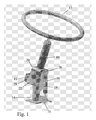
- Figure 1 shows an adjustable steering column made up of a first section 10 supporting a steering wheel 12 and a second section 14 which is secured to the vehicle chassis.
- the first section can pivot about pins 16 which connect two U-shaped brackets 20 and 22, welded respectively to the first and the second section of the steering column.
- a hydraulic spring and damper cylinder 18 extends between a bracket 24 welded to the lower section 14 of the steering column and a pin 26 mounted in the U-shaped bracket 20.
- the cylinder 18 supports the weight of the upper section 10 of the steering column and the steering wheel 12 during adjustment of their position and can be used to lock the section 10 of the steering column in any desired position.
- Movement of the steering wheel 12 towards the driver is limited by the pin 26 abutting the upper end of a plate 19 that is welded to the second section 14 of the steering column. Furthermore, a rearward extension 21 of the bracket 20 limits the movement of the steering wheel away from the driver by abutting the rear edge of the bracket 22.
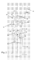
- sections 10 and 14 of the steering column there are journalled two sections of a steering shaft connecting the steering wheel 12 to the vehicle steering mechanism.
- the two sections are connected to one another by means of a universal joint to allow them to pivot relative to one another.
- the pivot axis defined by the pins 16 coincides with the centre of the universal joint.
- the pivot axis defined by the pins 16 is intentionally moved to be further away from the line of action of the cylinder 18 than the centre of the universal joint in the steering shaft, as this allows the cylinder 18 to be mounted nearer to the steering column so as to take up less space. If the pin 16 is offset sufficiently from the centre of the universal joint, then is it possible for the cylinder 18 to be positioned alongside the steering column, instead of being in front of it.
- a Cardan joint 40 comprising two forks 42 and 44 and a cross 46 serves to couple the first section 30 of the steering shaft to the second section 32. If the axis of the pins 16 were arranged, as in the prior art, to coincide with the centre of the cross 46 there would be no movement of the cross 46 axially relative to the steering wheel and the steering mechanism. The fork 44 could therefore be permanently secured to the second section 32 of the steering shaft.
- the centre of the cross moves in a circle centred on the pivot axis of the pins 16 during adjustment of the position of the steering wheel.
- its second fork 44 is formed integrally with a link 48 in the form of a tube having two diametrically opposed axially extending slots 50 in its end.
- the slots 20 receive the ends of a pin 52 mounted in a bore extending transversely through a ball 54 formed at the end of the second section 32 of the steering shaft.
- the link 48 can tilt relative to the second section 32 of the steering shaft by pivoting about the pin 52 and it can also move axially by the pin 52 sliding in the slots 50.
- the universal joint need not be a Cardan joint and other forms of coupling could be used to allow the universal joint to tilt and move axially relative to one of the sections of the steering shaft.
Landscapes
- Engineering & Computer Science (AREA)
- Chemical & Material Sciences (AREA)
- Combustion & Propulsion (AREA)
- Transportation (AREA)
- Mechanical Engineering (AREA)
- Steering Controls (AREA)
- Steering Control In Accordance With Driving Conditions (AREA)
Abstract
Description
- The present invention relates to a steering column for a vehicle which allows the rake of the steering wheel to be adjusted.
- It is known to form a steering column in two sections that can be pivoted relative to one another to allow adjustment of the position and rake of the steering wheel. A steering shaft connected to the steering wheel and journalled within the steering column is also formed in two sections which can pivot relative to one another with the steering column. A universal joint connects the sections of the steering shaft to one another and its centre (the point of intersection of the axes of the two sections of the shaft when they are not aligned with one another) lies on the pivot axis of the sections of the steering column.
- The two sections of the steering column are connected to one another by a spring and damper cylinder which can be used to lock the sections in any desired position and supports the weight of the steering wheel as its position is being adjusted. In order for the spring and damper cylinder to have the necessary leverage, it is necessary for its points of attachment to the sections of the steering column to lie on a line of action offset from the pivot axis. For this reason, attachment brackets are provided for the spring and damper cylinder which project from the sections of the steering column.
- A disadvantage of the known construction is that additional space is required to accommodate the spring and damper cylinder.
- With a view to mitigating the foregoing disadvantage, the present invention provides a steering column comprising two sections that are pivotable relative to one another to enable the position and rake of a steering wheel supported by a first of the sections to be adjusted, and a steering shaft formed in two sections which are journalled in the respective sections of the steering column and which are connected to one another by means of a universal joint, characterised in that the centre of the universal joint is offset from the pivot axis of the sections of the steering column.
- It is possible for the centre of the universal joint not to move as the first section of the steering column supporting the steering wheel is pivoted. In this case, it is necessary for both sections of the steering shaft to be extensible. This may be achieved, for example, by forming each section as a telescopically collapsible tube.
- In the preferred embodiment of the invention, however, the first section of the steering shaft connected to the steering wheel is of fixed length and the centre of the universal joint follows a circular path centred on the pivot axis of the steering column, the universal joint being connected for rotation with the second section of the steering column by means of an intermediate link that can move axially and pivot relative to the second section of the steering column.
- The intermediate link preferably comprises a tube having at its end elongated slots which receive a pin projecting laterally from a ball arranged at the end of the second section of the steering shaft. The pin allows the intermediate link to pivot relative to the second shaft while the elongated slots permit relative axial movement.
- The invention will now be described further, by way of example, with reference to the accompanying drawings, in which:
- Figure 1 is schematic perspective view of a steering column of the invention, and
- Figure 2 is a partial section through the steering column.
-
- Figure 1 shows an adjustable steering column made up of a
first section 10 supporting asteering wheel 12 and asecond section 14 which is secured to the vehicle chassis. The first section can pivot aboutpins 16 which connect twoU-shaped brackets damper cylinder 18 extends between abracket 24 welded to thelower section 14 of the steering column and apin 26 mounted in theU-shaped bracket 20. Thecylinder 18 supports the weight of theupper section 10 of the steering column and thesteering wheel 12 during adjustment of their position and can be used to lock thesection 10 of the steering column in any desired position. Movement of thesteering wheel 12 towards the driver is limited by thepin 26 abutting the upper end of aplate 19 that is welded to thesecond section 14 of the steering column. Furthermore, arearward extension 21 of thebracket 20 limits the movement of the steering wheel away from the driver by abutting the rear edge of thebracket 22. - Within the
sections steering wheel 12 to the vehicle steering mechanism. The two sections are connected to one another by means of a universal joint to allow them to pivot relative to one another. - In prior constructions of such an adjustable steering column, the pivot axis defined by the
pins 16 coincides with the centre of the universal joint. By contrast, in the illustrated embodiment of the invention, the pivot axis defined by thepins 16 is intentionally moved to be further away from the line of action of thecylinder 18 than the centre of the universal joint in the steering shaft, as this allows thecylinder 18 to be mounted nearer to the steering column so as to take up less space. If thepin 16 is offset sufficiently from the centre of the universal joint, then is it possible for thecylinder 18 to be positioned alongside the steering column, instead of being in front of it. - In Figure 2, the connection between the two
sections joint 40 comprising twoforks cross 46 serves to couple thefirst section 30 of the steering shaft to thesecond section 32. If the axis of thepins 16 were arranged, as in the prior art, to coincide with the centre of thecross 46 there would be no movement of thecross 46 axially relative to the steering wheel and the steering mechanism. Thefork 44 could therefore be permanently secured to thesecond section 32 of the steering shaft. However, as the pivot axis defined by thepins 16 is offset from the centre of thecross 46, and as the latter is mounted directly on thefirst section 30 of the steering shaft, the centre of the cross moves in a circle centred on the pivot axis of thepins 16 during adjustment of the position of the steering wheel. - In order to accommodate this movement of the centre of the Cardan joint, its
second fork 44 is formed integrally with alink 48 in the form of a tube having two diametrically opposed axially extendingslots 50 in its end. Theslots 20 receive the ends of apin 52 mounted in a bore extending transversely through aball 54 formed at the end of thesecond section 32 of the steering shaft. Thelink 48 can tilt relative to thesecond section 32 of the steering shaft by pivoting about thepin 52 and it can also move axially by thepin 52 sliding in theslots 50. - As an alternative to the embodiment shown in Figure 2, it would be possible to maintain the centre of the Cardan joint stationary if both the sections of the steering shaft were made extensible. This can be achieved by forming the sections of the steering shaft as telescopic tubes or by connecting the forks of the Cardan joint to the sections of the steering shaft using couplings that allow a certain degree of axial motion.
- It will be appreciated that various changes may be made to the described embodiment without departing from the scope of the invention as set out in the appended claims. For example, the universal joint need not be a Cardan joint and other forms of coupling could be used to allow the universal joint to tilt and move axially relative to one of the sections of the steering shaft.
Claims (5)
- A steering column comprising two sections (10, 14) that are pivotable relative to one another to enable the position and rake of a steering wheel (12) supported by a first (10) of the sections to be adjusted, and a steering shaft formed in two sections (30, 32) which are journalled in the respective sections (10, 14) of the steering column and which are connected to one another by means of a universal joint (40), and
characterised in that the centre of the universal joint is offset from the pivot axis (16) of the sections (10, 14) of the steering column. - A steering column according to claim 1, characterized in that the centre of the universal joint (40) does not move as the first section (10) of the steering column supporting the steering wheel (12) is pivoted and wherein both sections of the steering shaft (30, 32) are extensible.
- A steering column according to claim 1, characterized in that the first section (30) of the steering shaft connected to the steering wheel (12) is of fixed length and the centre of the universal joint (40) follows a circular path centred on the pivot axis (16) of the steering column, the universal joint (40) being connected for rotation with the second section (14) of the steering column by means of an intermediate link (48) that can move axially and pivot relative to the second section (14) of the steering column.
- A steering column according to claim 3, characterized in that the intermediate link (48) comprises a tube having at its end elongated slots (50) which receive a pin (52) projecting laterally from a ball (54) arranged at the end of the second section (32) of the steering shaft.
- A steering column according to any of the preceding claims, characterized in that a spring and damping cylinder (18) is connected between the two sections (10, 14) of the steering column.
Applications Claiming Priority (2)
| Application Number | Priority Date | Filing Date | Title |
|---|---|---|---|
| ITTO20040159 | 2004-03-11 | ||
| IT000159A ITTO20040159A1 (en) | 2004-03-11 | 2004-03-11 | ADJUSTABLE STEERING COLUMN FOR A VEHICLE |
Publications (3)
| Publication Number | Publication Date |
|---|---|
| EP1574414A2 true EP1574414A2 (en) | 2005-09-14 |
| EP1574414A3 EP1574414A3 (en) | 2005-10-19 |
| EP1574414B1 EP1574414B1 (en) | 2008-02-13 |
Family
ID=34814972
Family Applications (1)
| Application Number | Title | Priority Date | Filing Date |
|---|---|---|---|
| EP05101250A Expired - Lifetime EP1574414B1 (en) | 2004-03-11 | 2005-02-18 | Adjustable steering column for a vehicle |
Country Status (5)
| Country | Link |
|---|---|
| US (1) | US7603928B2 (en) |
| EP (1) | EP1574414B1 (en) |
| AT (1) | ATE385938T1 (en) |
| DE (1) | DE602005004679T2 (en) |
| IT (1) | ITTO20040159A1 (en) |
Families Citing this family (5)
| Publication number | Priority date | Publication date | Assignee | Title |
|---|---|---|---|---|
| US9254861B2 (en) * | 2012-05-25 | 2016-02-09 | Nsk Ltd. | Electric steering wheel position adjustment apparatus |
| JP6333191B2 (en) * | 2015-02-13 | 2018-05-30 | 本田技研工業株式会社 | Tilt steering device |
| JP6534178B1 (en) * | 2018-05-28 | 2019-06-26 | 三菱ロジスネクスト株式会社 | Steering device and cargo handling vehicle |
| DE102022208597B4 (en) | 2022-08-18 | 2026-03-05 | Carl Zeiss Microscopy Gmbh | Device for imaging and processing a sample with a focused particle beam |
| US12479291B1 (en) | 2024-11-07 | 2025-11-25 | Textron Inc. | Adjustable pedals |
Family Cites Families (17)
| Publication number | Priority date | Publication date | Assignee | Title |
|---|---|---|---|---|
| CH117915A (en) * | 1925-12-14 | 1927-01-17 | J Badertscher Otto | Braking device for motor vehicles with explosion engines. |
| US3198030A (en) * | 1961-07-20 | 1965-08-03 | Ford Motor Co | Adjustable steering column |
| US4331003A (en) * | 1979-07-26 | 1982-05-25 | Barry Wright Corporation | Flexible coupling |
| JPS5663557A (en) * | 1979-10-26 | 1981-05-30 | Nissan Motor Co Ltd | Steering gear |
| US4392670A (en) * | 1981-02-27 | 1983-07-12 | Clark Equipment Company | Pivoted steering column for lift truck |
| US4946195A (en) * | 1988-03-08 | 1990-08-07 | Mazda Motor Corporation | Steering assembly supporting construction of a motor vehicle |
| US4856927A (en) * | 1988-06-06 | 1989-08-15 | The Torrington Company | Midpoint connection for intermediate shaft subassembly |
| US5036942A (en) * | 1990-08-14 | 1991-08-06 | Ford New Holland, Inc. | Rotatable operator control unlocking mechanism |
| DE4235588A1 (en) * | 1992-10-22 | 1994-04-28 | Stabilus Gmbh | Hydropneumatic adjustment element |
| DE4238732C1 (en) * | 1992-11-17 | 1994-02-17 | Lemfoerder Metallwaren Ag | Adjustable steering column for motor vehicles |
| FR2699976B1 (en) * | 1992-12-30 | 1996-07-26 | Castellon Melchor Daumal | TELESCOPIC TREE. |
| DE19654273A1 (en) * | 1995-12-26 | 1997-07-03 | Aisin Seiki | Steering wheel position adjuster for vehicle with manual steering |
| DE69714945T2 (en) | 1996-11-12 | 2005-07-07 | Cnh Belgium N.V. | Four-way adjustable, base-mounted steering column for a combine harvester |
| DE19746790A1 (en) * | 1997-10-23 | 1999-05-06 | Daimler Chrysler Ag | Steering system for a motor vehicle |
| US6189405B1 (en) * | 1998-04-30 | 2001-02-20 | Kabushiki Kaisha Yamada Seisa Kusho | Position adjusting device for steering wheels |
| GB2349446A (en) | 1999-04-26 | 2000-11-01 | New Holland | Steering column aseembly |
| US6279953B1 (en) * | 1999-12-22 | 2001-08-28 | Trw Inc. | Flexible mount for an intermediate steering column |
-
2004
- 2004-03-11 IT IT000159A patent/ITTO20040159A1/en unknown
-
2005
- 2005-02-18 AT AT05101250T patent/ATE385938T1/en not_active IP Right Cessation
- 2005-02-18 EP EP05101250A patent/EP1574414B1/en not_active Expired - Lifetime
- 2005-02-18 DE DE602005004679T patent/DE602005004679T2/en not_active Expired - Lifetime
- 2005-03-10 US US11/077,473 patent/US7603928B2/en not_active Expired - Fee Related
Non-Patent Citations (1)
| Title |
|---|
| None |
Also Published As
| Publication number | Publication date |
|---|---|
| DE602005004679D1 (en) | 2008-03-27 |
| EP1574414A3 (en) | 2005-10-19 |
| DE602005004679T2 (en) | 2008-06-05 |
| EP1574414B1 (en) | 2008-02-13 |
| ATE385938T1 (en) | 2008-03-15 |
| US20050199086A1 (en) | 2005-09-15 |
| ITTO20040159A1 (en) | 2004-06-11 |
| US7603928B2 (en) | 2009-10-20 |
Similar Documents
| Publication | Publication Date | Title |
|---|---|---|
| US12409882B2 (en) | All-terrain vehicle | |
| US7878517B2 (en) | Vehicle axle apparatus | |
| US6695329B2 (en) | Saddle type vehicle | |
| JPH11321761A (en) | Motorcycle front wheel guidance system | |
| CN1840404B (en) | Steering wheel position adjustment device | |
| US6327928B1 (en) | Steering column shifter assembly | |
| JP2955549B2 (en) | Rack and pinion steering system for four-wheel drive vehicles | |
| JPH0687142U (en) | Shock absorption type steering column device with electric power steering device | |
| CN100369779C (en) | Electric Steering | |
| GB2107264A (en) | Vehicle steering mechanisms | |
| US4372418A (en) | Front set of wheels for an automobile vehicle | |
| EP1574414A2 (en) | Adjustable steering column for a vehicle | |
| US6647822B2 (en) | Vehicle shifter | |
| EP4656505A1 (en) | A system for steering a leaning motor vehicle with two front wheels | |
| JP2000103339A (en) | Steering column support device | |
| US20180127049A1 (en) | Collapsible flip-pivot bicycle | |
| HU220944B1 (en) | Front wheel suspension mainly for motorcycles | |
| KR101637577B1 (en) | Steering device for vehicle | |
| JP2002173047A (en) | Suspension member structure | |
| US12434758B2 (en) | Assembly for equipping motor vehicle with dual-steer capabilities | |
| JP3438707B2 (en) | Vehicle suspension device | |
| JPH115544A (en) | Steering control device | |
| JP2832963B2 (en) | Motorcycle power unit suspension system | |
| JP2017065668A (en) | vehicle | |
| CN117794754A (en) | Running gear for vehicles |
Legal Events
| Date | Code | Title | Description |
|---|---|---|---|
| PUAI | Public reference made under article 153(3) epc to a published international application that has entered the european phase |
Free format text: ORIGINAL CODE: 0009012 |
|
| PUAL | Search report despatched |
Free format text: ORIGINAL CODE: 0009013 |
|
| AK | Designated contracting states |
Kind code of ref document: A2 Designated state(s): AT BE BG CH CY CZ DE DK EE ES FI FR GB GR HU IE IS IT LI LT LU MC NL PL PT RO SE SI SK TR |
|
| AX | Request for extension of the european patent |
Extension state: AL BA HR LV MK YU |
|
| AK | Designated contracting states |
Kind code of ref document: A3 Designated state(s): AT BE BG CH CY CZ DE DK EE ES FI FR GB GR HU IE IS IT LI LT LU MC NL PL PT RO SE SI SK TR |
|
| AX | Request for extension of the european patent |
Extension state: AL BA HR LV MK YU |
|
| 17P | Request for examination filed |
Effective date: 20060403 |
|
| AKX | Designation fees paid |
Designated state(s): AT BE BG CH CY CZ DE DK EE ES FI FR GB GR HU IE IS IT LI LT LU MC NL PL PT RO SE SI SK TR |
|
| 17Q | First examination report despatched |
Effective date: 20060725 |
|
| GRAP | Despatch of communication of intention to grant a patent |
Free format text: ORIGINAL CODE: EPIDOSNIGR1 |
|
| GRAS | Grant fee paid |
Free format text: ORIGINAL CODE: EPIDOSNIGR3 |
|
| GRAA | (expected) grant |
Free format text: ORIGINAL CODE: 0009210 |
|
| AK | Designated contracting states |
Kind code of ref document: B1 Designated state(s): AT BE BG CH CY CZ DE DK EE ES FI FR GB GR HU IE IS IT LI LT LU MC NL PL PT RO SE SI SK TR |
|
| REG | Reference to a national code |
Ref country code: GB Ref legal event code: FG4D |
|
| REG | Reference to a national code |
Ref country code: CH Ref legal event code: EP |
|
| REG | Reference to a national code |
Ref country code: IE Ref legal event code: FG4D |
|
| REF | Corresponds to: |
Ref document number: 602005004679 Country of ref document: DE Date of ref document: 20080327 Kind code of ref document: P |
|
| PG25 | Lapsed in a contracting state [announced via postgrant information from national office to epo] |
Ref country code: IS Free format text: LAPSE BECAUSE OF FAILURE TO SUBMIT A TRANSLATION OF THE DESCRIPTION OR TO PAY THE FEE WITHIN THE PRESCRIBED TIME-LIMIT Effective date: 20080613 Ref country code: FI Free format text: LAPSE BECAUSE OF FAILURE TO SUBMIT A TRANSLATION OF THE DESCRIPTION OR TO PAY THE FEE WITHIN THE PRESCRIBED TIME-LIMIT Effective date: 20080213 Ref country code: ES Free format text: LAPSE BECAUSE OF FAILURE TO SUBMIT A TRANSLATION OF THE DESCRIPTION OR TO PAY THE FEE WITHIN THE PRESCRIBED TIME-LIMIT Effective date: 20080524 |
|
| NLV1 | Nl: lapsed or annulled due to failure to fulfill the requirements of art. 29p and 29m of the patents act | ||
| ET | Fr: translation filed | ||
| PG25 | Lapsed in a contracting state [announced via postgrant information from national office to epo] |
Ref country code: AT Free format text: LAPSE BECAUSE OF FAILURE TO SUBMIT A TRANSLATION OF THE DESCRIPTION OR TO PAY THE FEE WITHIN THE PRESCRIBED TIME-LIMIT Effective date: 20080213 |
|
| PG25 | Lapsed in a contracting state [announced via postgrant information from national office to epo] |
Ref country code: BE Free format text: LAPSE BECAUSE OF FAILURE TO SUBMIT A TRANSLATION OF THE DESCRIPTION OR TO PAY THE FEE WITHIN THE PRESCRIBED TIME-LIMIT Effective date: 20080213 Ref country code: PL Free format text: LAPSE BECAUSE OF FAILURE TO SUBMIT A TRANSLATION OF THE DESCRIPTION OR TO PAY THE FEE WITHIN THE PRESCRIBED TIME-LIMIT Effective date: 20080213 Ref country code: SI Free format text: LAPSE BECAUSE OF FAILURE TO SUBMIT A TRANSLATION OF THE DESCRIPTION OR TO PAY THE FEE WITHIN THE PRESCRIBED TIME-LIMIT Effective date: 20080213 |
|
| PG25 | Lapsed in a contracting state [announced via postgrant information from national office to epo] |
Ref country code: SK Free format text: LAPSE BECAUSE OF FAILURE TO SUBMIT A TRANSLATION OF THE DESCRIPTION OR TO PAY THE FEE WITHIN THE PRESCRIBED TIME-LIMIT Effective date: 20080213 Ref country code: NL Free format text: LAPSE BECAUSE OF FAILURE TO SUBMIT A TRANSLATION OF THE DESCRIPTION OR TO PAY THE FEE WITHIN THE PRESCRIBED TIME-LIMIT Effective date: 20080213 Ref country code: DK Free format text: LAPSE BECAUSE OF FAILURE TO SUBMIT A TRANSLATION OF THE DESCRIPTION OR TO PAY THE FEE WITHIN THE PRESCRIBED TIME-LIMIT Effective date: 20080213 Ref country code: CZ Free format text: LAPSE BECAUSE OF FAILURE TO SUBMIT A TRANSLATION OF THE DESCRIPTION OR TO PAY THE FEE WITHIN THE PRESCRIBED TIME-LIMIT Effective date: 20080213 Ref country code: PT Free format text: LAPSE BECAUSE OF FAILURE TO SUBMIT A TRANSLATION OF THE DESCRIPTION OR TO PAY THE FEE WITHIN THE PRESCRIBED TIME-LIMIT Effective date: 20080714 Ref country code: SE Free format text: LAPSE BECAUSE OF FAILURE TO SUBMIT A TRANSLATION OF THE DESCRIPTION OR TO PAY THE FEE WITHIN THE PRESCRIBED TIME-LIMIT Effective date: 20080513 Ref country code: MC Free format text: LAPSE BECAUSE OF NON-PAYMENT OF DUE FEES Effective date: 20080228 |
|
| PG25 | Lapsed in a contracting state [announced via postgrant information from national office to epo] |
Ref country code: RO Free format text: LAPSE BECAUSE OF FAILURE TO SUBMIT A TRANSLATION OF THE DESCRIPTION OR TO PAY THE FEE WITHIN THE PRESCRIBED TIME-LIMIT Effective date: 20080213 |
|
| PLBE | No opposition filed within time limit |
Free format text: ORIGINAL CODE: 0009261 |
|
| STAA | Information on the status of an ep patent application or granted ep patent |
Free format text: STATUS: NO OPPOSITION FILED WITHIN TIME LIMIT |
|
| 26N | No opposition filed |
Effective date: 20081114 |
|
| PG25 | Lapsed in a contracting state [announced via postgrant information from national office to epo] |
Ref country code: EE Free format text: LAPSE BECAUSE OF FAILURE TO SUBMIT A TRANSLATION OF THE DESCRIPTION OR TO PAY THE FEE WITHIN THE PRESCRIBED TIME-LIMIT Effective date: 20080213 Ref country code: IE Free format text: LAPSE BECAUSE OF NON-PAYMENT OF DUE FEES Effective date: 20080218 Ref country code: LT Free format text: LAPSE BECAUSE OF FAILURE TO SUBMIT A TRANSLATION OF THE DESCRIPTION OR TO PAY THE FEE WITHIN THE PRESCRIBED TIME-LIMIT Effective date: 20080213 |
|
| PG25 | Lapsed in a contracting state [announced via postgrant information from national office to epo] |
Ref country code: BG Free format text: LAPSE BECAUSE OF FAILURE TO SUBMIT A TRANSLATION OF THE DESCRIPTION OR TO PAY THE FEE WITHIN THE PRESCRIBED TIME-LIMIT Effective date: 20080513 |
|
| PG25 | Lapsed in a contracting state [announced via postgrant information from national office to epo] |
Ref country code: CY Free format text: LAPSE BECAUSE OF FAILURE TO SUBMIT A TRANSLATION OF THE DESCRIPTION OR TO PAY THE FEE WITHIN THE PRESCRIBED TIME-LIMIT Effective date: 20080213 |
|
| REG | Reference to a national code |
Ref country code: CH Ref legal event code: PL |
|
| PG25 | Lapsed in a contracting state [announced via postgrant information from national office to epo] |
Ref country code: LI Free format text: LAPSE BECAUSE OF NON-PAYMENT OF DUE FEES Effective date: 20090228 Ref country code: CH Free format text: LAPSE BECAUSE OF NON-PAYMENT OF DUE FEES Effective date: 20090228 |
|
| PG25 | Lapsed in a contracting state [announced via postgrant information from national office to epo] |
Ref country code: LU Free format text: LAPSE BECAUSE OF NON-PAYMENT OF DUE FEES Effective date: 20080218 Ref country code: HU Free format text: LAPSE BECAUSE OF FAILURE TO SUBMIT A TRANSLATION OF THE DESCRIPTION OR TO PAY THE FEE WITHIN THE PRESCRIBED TIME-LIMIT Effective date: 20080814 |
|
| PG25 | Lapsed in a contracting state [announced via postgrant information from national office to epo] |
Ref country code: TR Free format text: LAPSE BECAUSE OF FAILURE TO SUBMIT A TRANSLATION OF THE DESCRIPTION OR TO PAY THE FEE WITHIN THE PRESCRIBED TIME-LIMIT Effective date: 20080213 |
|
| PG25 | Lapsed in a contracting state [announced via postgrant information from national office to epo] |
Ref country code: GR Free format text: LAPSE BECAUSE OF FAILURE TO SUBMIT A TRANSLATION OF THE DESCRIPTION OR TO PAY THE FEE WITHIN THE PRESCRIBED TIME-LIMIT Effective date: 20080514 |
|
| REG | Reference to a national code |
Ref country code: DE Ref legal event code: R082 Ref document number: 602005004679 Country of ref document: DE Representative=s name: PATENTANWAELTE WALLACH, KOCH & PARTNER, DE |
|
| REG | Reference to a national code |
Ref country code: DE Ref legal event code: R082 Ref document number: 602005004679 Country of ref document: DE Representative=s name: PATENTANWAELTE WALLACH, KOCH & PARTNER, DE Effective date: 20140623 Ref country code: DE Ref legal event code: R081 Ref document number: 602005004679 Country of ref document: DE Owner name: CNH INDUSTRIAL ITALIA S.P.A., IT Free format text: FORMER OWNER: CNH ITALIA S.P.A., MODENA, IT Effective date: 20140623 Ref country code: DE Ref legal event code: R082 Ref document number: 602005004679 Country of ref document: DE Representative=s name: PATENTANWAELTE WALLACH, KOCH, DR. HAIBACH, FEL, DE Effective date: 20140623 |
|
| REG | Reference to a national code |
Ref country code: FR Ref legal event code: CD Owner name: CNH INDUSTRIAL ITALIA S.P.A. Effective date: 20150313 |
|
| REG | Reference to a national code |
Ref country code: FR Ref legal event code: PLFP Year of fee payment: 12 |
|
| REG | Reference to a national code |
Ref country code: FR Ref legal event code: PLFP Year of fee payment: 13 |
|
| REG | Reference to a national code |
Ref country code: FR Ref legal event code: PLFP Year of fee payment: 14 |
|
| PGFP | Annual fee paid to national office [announced via postgrant information from national office to epo] |
Ref country code: GB Payment date: 20200219 Year of fee payment: 16 |
|
| PGFP | Annual fee paid to national office [announced via postgrant information from national office to epo] |
Ref country code: FR Payment date: 20200219 Year of fee payment: 16 |
|
| REG | Reference to a national code |
Ref country code: DE Ref legal event code: R082 Ref document number: 602005004679 Country of ref document: DE Representative=s name: MEISSNER BOLTE PATENTANWAELTE RECHTSANWAELTE P, DE |
|
| REG | Reference to a national code |
Ref country code: DE Ref legal event code: R084 Ref document number: 602005004679 Country of ref document: DE |
|
| GBPC | Gb: european patent ceased through non-payment of renewal fee |
Effective date: 20210218 |
|
| PG25 | Lapsed in a contracting state [announced via postgrant information from national office to epo] |
Ref country code: GB Free format text: LAPSE BECAUSE OF NON-PAYMENT OF DUE FEES Effective date: 20210218 Ref country code: FR Free format text: LAPSE BECAUSE OF NON-PAYMENT OF DUE FEES Effective date: 20210228 |
|
| PGFP | Annual fee paid to national office [announced via postgrant information from national office to epo] |
Ref country code: IT Payment date: 20230210 Year of fee payment: 19 |
|
| PGFP | Annual fee paid to national office [announced via postgrant information from national office to epo] |
Ref country code: DE Payment date: 20240228 Year of fee payment: 20 |
|
| REG | Reference to a national code |
Ref country code: DE Ref legal event code: R071 Ref document number: 602005004679 Country of ref document: DE |