EP1574411B1 - Foot pedal device for a vehicle - Google Patents
Foot pedal device for a vehicle Download PDFInfo
- Publication number
- EP1574411B1 EP1574411B1 EP05004497A EP05004497A EP1574411B1 EP 1574411 B1 EP1574411 B1 EP 1574411B1 EP 05004497 A EP05004497 A EP 05004497A EP 05004497 A EP05004497 A EP 05004497A EP 1574411 B1 EP1574411 B1 EP 1574411B1
- Authority
- EP
- European Patent Office
- Prior art keywords
- piston
- foot pedal
- force transmission
- pedal device
- spring
- Prior art date
- Legal status (The legal status is an assumption and is not a legal conclusion. Google has not performed a legal analysis and makes no representation as to the accuracy of the status listed.)
- Expired - Lifetime
Links
- 230000005540 biological transmission Effects 0.000 claims description 32
- XAGFODPZIPBFFR-UHFFFAOYSA-N aluminium Chemical compound [Al] XAGFODPZIPBFFR-UHFFFAOYSA-N 0.000 claims description 2
- 229910052782 aluminium Inorganic materials 0.000 claims description 2
- 238000006073 displacement reaction Methods 0.000 claims description 2
- 238000001125 extrusion Methods 0.000 claims description 2
- 239000004411 aluminium Substances 0.000 claims 1
- 238000000034 method Methods 0.000 claims 1
- 230000001105 regulatory effect Effects 0.000 claims 1
- 230000001419 dependent effect Effects 0.000 description 2
- 230000001939 inductive effect Effects 0.000 description 2
- 238000004519 manufacturing process Methods 0.000 description 2
- 238000010276 construction Methods 0.000 description 1
- 230000007547 defect Effects 0.000 description 1
- 230000000994 depressogenic effect Effects 0.000 description 1
- 230000000977 initiatory effect Effects 0.000 description 1
Images
Classifications
-
- G—PHYSICS
- G05—CONTROLLING; REGULATING
- G05G—CONTROL DEVICES OR SYSTEMS INSOFAR AS CHARACTERISED BY MECHANICAL FEATURES ONLY
- G05G1/00—Controlling members, e.g. knobs or handles; Assemblies or arrangements thereof; Indicating position of controlling members
- G05G1/30—Controlling members actuated by foot
-
- B—PERFORMING OPERATIONS; TRANSPORTING
- B60—VEHICLES IN GENERAL
- B60T—VEHICLE BRAKE CONTROL SYSTEMS OR PARTS THEREOF; BRAKE CONTROL SYSTEMS OR PARTS THEREOF, IN GENERAL; ARRANGEMENT OF BRAKING ELEMENTS ON VEHICLES IN GENERAL; PORTABLE DEVICES FOR PREVENTING UNWANTED MOVEMENT OF VEHICLES; VEHICLE MODIFICATIONS TO FACILITATE COOLING OF BRAKES
- B60T15/00—Construction arrangement, or operation of valves incorporated in power brake systems and not covered by groups B60T11/00 or B60T13/00
- B60T15/02—Application and release valves
- B60T15/04—Driver's valves
- B60T15/14—Driver's valves influencing electric control means
Definitions
- the invention relates to a foot pedal device of a vehicle according to the preamble of claim 1.
- the disadvantage here is that the pin tilt in his leadership on the potentiometer or stuck so no signal or a false signal is delivered to the controller, which leads to a high security risk, especially in electric brake pedal modules. Furthermore, the head-side arrangement of the potentiometer unit leads to a relatively large axial extent of the submittedpedal nails so that it builds relatively high, which is disadvantageous in view of the limited footwell of motor vehicles.
- an inductive sensor is disclosed, which is also arranged in axial extension.
- the potentiometer 1 is arranged laterally.
- the actuating pin is actuated by means of a cooperating with a plunger plate, which requires a larger construction cost, since the plate must be additionally provided.
- the present invention is based on the object to further develop a coupledpedal gear of the type mentioned in such a way that it has a higher reliability at low height.
- At least the plunger seat, the driver and the spring receptacle is designed as a one-piece combined power transmission and driver element.
- the invention provides that the driver of the combined power transmission and driver element of the plunger receptacle (4) and the spring receptacle (30) axially interposed is formed as a circumferential annular groove, in which an actuating pin engages at least one potentiometer, and that the potentiometer with respect to the Combined power transmission and driver element is arranged laterally.
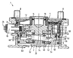
- FIG. 1 shows a sectional illustration of a foot pedal device of a commercial vehicle according to the invention in a preferred embodiment.
- FIG.1 A preferred embodiment of a foot pedal device 1 of a commercial vehicle is shown, which transmits the pedal force exerted on an unillustrated foot pedal, for example a foot brake pedal, to a piston 2
- an unillustrated foot pedal for example a foot brake pedal
- This ram receiving portion 4 is formed in a projecting into a through hole of a closure cover 12 hollow pin 14 of the combined power transmission and driver element 10.
- the closure lid 12 is preferably made of plastic.
- An axially adjoining the plunger receiving portion 4 middle portion of the combined power transmission and driver element 10 is cooperating with a Pedalwegetzrich 18 driver portion 20 which preferably has a circumferential annular groove 22 in which an actuating pin 24 engages preferably of the two Pedalweg Stammauer forming potentiometers 18 which, depending on the axial position of the combined power transmission and driver element 10, generate electrical pedal travel signals for an electronic control device of an electro-pneumatic braking device which is not shown for reasons of scale. Transverse to a longitudinal axis of the housing 6 outwardly projecting pins 26 for the potentiometer 18 are present.
- the braking device is designed in such a way that, depending on the pedal travel signal, it generates an electrical actuating signal for brake cylinders that actuate brake cylinders.
- the potentiometer 18, the electronic control unit and the brake modules together form an electrical brake circuit of the braking device.
- the spring device 28 preferably consists of two helical springs 40, 42 inserted coaxially into one another and at the ends on the centering pins 34, 38 of the spring receiving section 30 and the piston 2.
- An outer helical spring 42 of the spring device 28 is in each case cup-shaped over its outer diameter on the inner diameter of a wall Recess 32, 36 and an inner coil spring 40 on the outer diameter of the Zentrierzapfens 34, 38 of the spring receiving portion 30 of the combined power transmission and driver element 10 and the piston 2 out.
- an axial force between the piston 2 and the combined power transmission and driver element 10 can only be transmitted by the spring device 28.
- the combined power transmission and driver element 10 thus consists of three axially successively arranged sections, which are combined in a single integral component 10: the plunger receiving portion 4, the driver portion 20 and the spring receiving portion 30.
- the combined power transmission and driver element 10 is preferably made of aluminum Alternatively, it may be an after-press-hardened extrusion molding or made of any other material.
- At least the spring receiving portion 30 of the combined power transmission and driver element 10 is guided linearly on the piston 2. This can for example, be accomplished by the fact that on the wall of the cup-shaped recess 32 of the spring receiving portion 30 of the combined power transmission and driver element 10, a radially outer annular shoulder 44 is formed, which is guided on the inner diameter of the wall of the cup-shaped recess 36 of the piston 2. In order to carry a running on the radially inner diameter of the wall 36 of the recess 36 of the piston 2 along the guide ring 46, the annular shoulder 44 of the spring receiving portion 30 of the combined power transmission and driver element 10 is provided with a radially outer annular groove. Alternatively, the piston 2 could also be guided on the inner diameter of the wall of the recess 32 of the spring receiving portion 30 of the combined power transmission and driver element 10.
- axial movement stops for the annular shoulder 44 are formed, for example in the form of a inserted into a radially inner annular groove of the wall 36 of the recess 36 of the piston 2 ring 48 and an end face of the bottom 50 of the recess 36 of the piston 2.
- axial movement stops for the annular shoulder 44 are formed, for example in the form of a inserted into a radially inner annular groove of the wall 36 of the recess 36 of the piston 2 ring 48 and an end face of the bottom 50 of the recess 36 of the piston 2.
- the piston 2 is guided in the housing 6 preferably by a held on its outer diameter guide ring 52 linear.
- a limited by the piston 2 pressure chamber 54 is sealed by an outer diameter of the piston 2 held O-ring 56 against the interior of the housing 6 and against the environment.
- the piston 2 and the pressure chamber 54 form parts of a purely pneumatic brake circuit of the braking device, as the pressure prevailing in the pressure chamber 54 and dependent on the axial position of the piston 2 pressure can control the brake pressure in the brake cylinders without the presence of the electrical path signals of the potentiometer 18.
- the piston 2 carries on its end face a valve seat ring 62 of an otherwise not shown Valve, through which supply pressure can flow into the pressure chamber 54.
- the valve seat ring 62 is formed integrally with the piston 2.
- the operation of the proposedpedal wisdom 1 is as follows: Upon actuation of the consideredspedals the introduction of the actuating force takes place in the solvedpedal wisdom 1 via the push rod, not shown in the plunger receiving portion 4. This causes a linear displacement of the combined power transmission and driver element 10, in the Figure down, whereby the driver portion 20 entrains the adjusting pin 24 of the potentiometer 18, which then generate the path signals for the electronic control unit of the electro-pneumatic braking device. In addition, the coil springs 40, 42 of the spring device 28 transmit the actuating force to the piston 2.
- the brake pressure in the brake cylinders can not be controlled by electrical signals.
- the pneumatic brake circuit of the braking device acts as an underlying safety level, since a pneumatic control signal in the form of changing pressure in the pressure chamber 54 is always generated as a result of the piston movement, depending on the then changes the brake pressure in the brake cylinders.
Landscapes
- Engineering & Computer Science (AREA)
- Physics & Mathematics (AREA)
- General Physics & Mathematics (AREA)
- Automation & Control Theory (AREA)
- Transportation (AREA)
- Mechanical Engineering (AREA)
- Braking Elements And Transmission Devices (AREA)
- Braking Systems And Boosters (AREA)
- Mechanical Control Devices (AREA)
Abstract
Description
Die Erfindung geht aus von einer Fußpedaleinrichtung eines Fahrzeugs nach der Gattung des Anspruchs 1.The invention relates to a foot pedal device of a vehicle according to the preamble of claim 1.
Aus dem Stand der Technik ist eine Fußpedaleinrichtung eines Nutzfahrzeugs bekannt, bei welcher die Stößelaufnahme, der Mitnehmer sowie die Federaufnahme jeweils getrennte, aneinander befestigte Bauteile sind. Hierfür sind mehrere Zentrierflächen sowie einige Fertigungsschritte notwendig, um die einzelnen Bauteile aneinander zu montieren.From the prior art, a Fußpedaleinrichtung a commercial vehicle is known in which the plunger seat, the driver and the spring seat are each separate, fastened together components. For this purpose, several centering surfaces and some manufacturing steps are necessary to mount the individual components together.
Bei der gattungsgemäßen Fußpedaleinrichtung greift ein Stift eines Potentiometers federbelastet an einer oberen Stirnfläche des kombinierten Kraftübertragungs- und Mitnehmerelements an, wobei der Stift umso mehr axial verfährt je weiter das Pedal niedergetreten wird, so dass in dem Potentiometer ein dem Pedalweg proportionales elektrisches Signal für ein Steuergerät eines beispielsweise elektrischen Bremskreises erzeugt wird.In the generic Fußpedaleinrichtung a pin of a potentiometer spring loaded engages an upper end face of the combined power transmission and driver element, the pin the more axially moves the further the pedal is depressed, so that in the potentiometer a the pedal travel proportional electrical signal for a controller an example electric brake circuit is generated.
Nachteilig dabei ist, dass der Stift in seiner Führung am Potentiometer verkanten oder hängen blieben kann somit kein Signal oder ein falsches Signal an das Steuergerät geliefert wird, was vor allem bei elektrischen Bremspedalmoduln zu einem hohen Sicherheitsrisiko führt. Weiterhin führt die kopfseitige Anordnung der Potentiometereinheit zu einer relativ großen axialen Ausdehnung der Fußpedaleinrichtung, so dass diese relativ hoch baut, was angesichts des begrenzten Fußraums von Kraftfahrzeugen von Nachteil ist.The disadvantage here is that the pin tilt in his leadership on the potentiometer or stuck so no signal or a false signal is delivered to the controller, which leads to a high security risk, especially in electric brake pedal modules. Furthermore, the head-side arrangement of the potentiometer unit leads to a relatively large axial extent of the Fußpedaleinrichtung so that it builds relatively high, which is disadvantageous in view of the limited footwell of motor vehicles.
Dokument
Gemäß
Bei der
Nach der
Der vorliegenden Erfindung liegt demgegenüber die Aufgabe zugrunde, eine Fußpedaleinrichtung der eingangs erwähnten Art derart weiter zu entwickeln, dass es bei geringer Bauhöhe eine höhere Funktionssicherheit aufweist.The present invention is based on the object to further develop a Fußpedaleinrichtung of the type mentioned in such a way that it has a higher reliability at low height.
Erfindungsgemäß wird diese Aufgabe durch die Merkmale des Anspruchs 1 gelöst.According to the invention, this object is solved by the features of claim 1.
Gemäß Anspruch 1 wird zumindest die Stößelaufnahme, den Mitnehmer und die Federaufnahme als einstückiges kombiniertes Kraftübertragungs- und Mitnehmerelement ausgeführt. Dadurch können eine Reihe von Montage- und Fertigungsschritten eingespart werden, wodurch die Fußpedaleinrichtung einfacher und kostengünstiger fertigbar ist.According to claim 1, at least the plunger seat, the driver and the spring receptacle is designed as a one-piece combined power transmission and driver element. As a result, a number of assembly and manufacturing steps can be saved, whereby the Fußpedaleinrichtung is easier and less expensive manufacturable.
Weiterhin ist erfindungsgemäß vorgesehen, dass der Mitnehmer des kombinierten Kraftübertragungs- und Mitnehmerelements der Stößelaufnahme (4) und der Federaufnahme (30) axial zwischenangeordnet als umlaufende Ringnut ausgebildet ist, in welche ein Stellstift wenigstens eines Potentiometers eingreift, und dass das Potentiometer in Bezug zu dem kombinierten Kraftübertragungs- und Mitnehmerelement seitlich angeordnet ist.Furthermore, the invention provides that the driver of the combined power transmission and driver element of the plunger receptacle (4) and the spring receptacle (30) axially interposed is formed as a circumferential annular groove, in which an actuating pin engages at least one potentiometer, and that the potentiometer with respect to the Combined power transmission and driver element is arranged laterally.
Durch die in den Unteransprüchen aufgeführten Maßnahmen sind vorteilhafte Weiterbildungen und Verbesserungen der im Anspruch 1 angegebenen Erfindung möglich.The measures listed in the dependent claims advantageous refinements and improvements of claim 1 invention are possible.
Ein Ausführungsbeispiel der Erfindung ist in der Zeichnung dargestellt und in der nachfolgenden Beschreibung näher erläutert. In der Zeichnung zeigt die einzigeAn embodiment of the invention is illustrated in the drawing and explained in more detail in the following description. In the drawing shows the only one
Figur eine Schnittdarstellung einer Fußpedaleinrichtung eines Nutzfahrzeugs gemäß der Erfindung in einer bevorzugten Ausführungsform.FIG. 1 shows a sectional illustration of a foot pedal device of a commercial vehicle according to the invention in a preferred embodiment.
In
überträgt, an welchem ein den Bremsdruck in Bremszylindern beeinflussender Druck ansteht. Die Einleitung der Betätigungskraft in die Fußpedaleinrichtung 1 erfolgt über eine nicht gezeigte Stößelstange, welche in einen Stößelaufnahmeabschnitt 4 der Fußpedaleinrichtung eingreift.transmits, at which a brake pressure in brake cylinders influencing pressure is present. The initiation of the actuating force in the Fußpedaleinrichtung 1 via a pushrod, not shown, which engages in a
Die Fußpedaleinrichtung 1 hat ein vorzugsweise zylindrisches Gehäuse 6, das über Anschlusszapfen 8 an einem aus Maßstabsgründen nicht gezeigten Fußpedallagerbock befestigbar ist, von welchem sich die vom Fußpedal betätigte Stößelstange weg erstreckt, d.h. bei Betätigung des Fußpedals vollzieht die Stößelstange eine lineare Ein- bzw. Ausfahrbewegung.The Fußpedaleinrichtung 1 has a preferably
An ihrer zur Stößelstange gewandten Stirnfläche eines kombinierten Kraftübertragungs- und Mitnehmerelements 10 ist der sacklochförmige Stößelaufnahmeabschnitt 4 zum Eingriff der Stößelstange und zur Übertragung der auf den Stößel wirkenden Pedalkraft auf das kombinierte Kraftübertragungs- und Mitnehmerelement 10 angeordnet. Dieser Stößelaufnahmeabschnitt 4 ist in einem in eine Durchgangsöffnung eines Verschlussdeckels 12 ragenden Hohlzapfen 14 des kombinierten Kraftübertragungs- und Mitnehmerelements 10 ausgebildet. Der Verschlussdeckel 12 besteht vorzugsweise aus Kunststoff. Mittels eines in einer radial äußeren Ringnut des Hohlzapfens 14 gehaltenen O-Rings 16 erfolgt eine Abdichtung des Inneren des Gehäuses 6 gegenüber der Umgebung.On its end facing the push rod end face of a combined power transmission and driver element 10 of the blind hole-shaped
Einem sich axial an den Stößelaufnahmeabschnitt 4 anschließenden Mittelabschnitt des kombinierten Kraftübertragungs- und Mitnehmerelements 10 ist ein mit einem Pedalwegaufnehmer 18 zusammenwirkender Mitnehmerabschnitt 20 angeformt, welcher bevorzugt eine umlaufende Ringnut 22 aufweist, in welche ein Stellstift 24 von vorzugsweise zwei den Pedalwegaufnehmer bildenden Potentiometern 18 eingreift, welche abhängig von der axialen Position des kombinierten Kraftübertragungs- und Mitnehmerelements 10 elektrische Pedalwegsignale für ein aus Maßstabsgründen nicht gezeigtes elektronisches Steuergerät einer elektro-pneumatischen Bremseinrichtung erzeugen. Quer zu einer Längsachse des Gehäuses 6 sind nach außen ragende Anschlussstifte 26 für die Potentiometer 18 vorhanden. Die Bremseinrichtung ist derart ausgebildet, dass sie abhängig vom Pedalwegsignal ein elektrisches Stellsignal für Bremszylinder ansteuernde Bremsmodule erzeugt. Die Potentiometer 18, das elektronische Steuergerät und die Bremsmodule bilden zusammen einen elektrischen Bremskreis der Bremseinrichtung.An axially adjoining the
An dem vom Stößelaufnahmeabschnitt 4 abgewandten Ende des kombinierten Kraftübertragungs- und Mitnehmerelements 10 ist eine Federeinrichtung 28 angeordnet, die sich einendseitig an einem Federaufnahmeabschnitt 30 des kombinierten Kraftübertragungs- und Mitnehmerelements 10 und anderendseitig an dem im Gehäuse 6 verschieblichen Kolben 2 abstützt. Der Federaufnahmeabschnitt 30 weist eine becherförmige, zum Kolben 2 hin offene Ausnehmung 32 mit einem zentralen Zentrierzapfen 34 auf. Der hierzu koaxiale Kolben 2 hat ebenfalls eine becherförmige, zum Federaufnahmeabschnitt 30 des kombinierten Kraftübertragungs- und Mitnehmerelements 10 hin offene Ausnehmung 36 mit einem zentralen Zentrierzapfen 38.At the end facing away from the
Die Federeinrichtung 28 besteht vorzugsweise aus zwei koaxial ineinander und endseitig jeweils auf den Zentrierzapfen 34, 38 des Federaufnahmeabschnitts 30 bzw. des Kolbens 2 gesteckten Schraubenfedern 40, 42. Eine äußere Schraubenfeder 42 der Federeinrichtung 28 ist über ihren Außendurchmesser jeweils am Innendurchmesser einer Wandung der becherförmigen Ausnehmung 32, 36 und eine innere Schraubenfeder 40 am Außendurchmesser des Zentrierzapfens 34, 38 des Federaufnahmeabschnitts 30 des kombinierten Kraftübertragungs- und Mitnehmerelements 10 bzw. des Kolbens 2 geführt. Von Reibungskräften abgesehen kann eine axiale Kraft zwischen dem Kolben 2 und dem kombinierten Kraftübertragungs- und Mitnehmerelement 10 lediglich durch die Federeinrichtung 28 übertragen werden.The spring device 28 preferably consists of two
Das kombinierte Kraftübertragungs- und Mitnehmerelement 10 besteht folglich aus drei axial hintereinander angeordneten Abschnitten, welche in einem einzigen einstückigen Bauteil 10 zusammengefasst sind : Dem Stößelaufnahmeabschnitt 4, dem Mitnehmerabschnitt 20 und dem Federaufnahmeabschnitt 30. Das kombinierte Kraftübertragungs- und Mitnehmerelement 10 besteht weiterhin vorzugsweise aus Aluminium, alternativ kann es ein nach dem Pressvorgang warm ausgehärteter Fließpressformling sein oder aus irgendeinem anderen Material bestehen.The combined power transmission and driver element 10 thus consists of three axially successively arranged sections, which are combined in a single integral component 10: the
Zumindest der Federaufnahmeabschnitt 30 des kombinierten Kraftübertragungs- und Mitnehmerelements 10 ist am Kolben 2 linear geführt. Dies kann beispielsweise dadurch bewerkstelligt sein, dass an der Wandung der becherförmigen Ausnehmung 32 des Federaufnahmeabschnitts 30 des kombinierten Kraftübertragungs- und Mitnehmerelements 10 eine radial äußere Ringschulter 44 ausgebildet ist, die am Innendurchmesser der Wandung der becherförmigen Ausnehmung 36 des Kolbens 2 geführt ist. Um einen am radial inneren Durchmesser der Wandung der Ausnehmung 36 des Kolbens 2 entlang laufenden Führungsring 46 zu tragen, ist die Ringschulter 44 des Federaufnahmeabschnitts 30 des kombinierten Kraftübertragungs- und Mitnehmerelements 10 mit einer radial äußeren Ringnut versehen. Alternativ könnte der Kolben 2 auch am Innendurchmesser der Wandung der Ausnehmung 32 des Federaufnahmeabschnitts 30 des kombinierten Kraftübertragungs- und Mitnehmerelements 10 geführt sein.At least the
Am Kolben 2 sind axiale Bewegungsanschläge für die Ringschulter 44 ausgebildet, beispielsweise in Form eines in eine radial innere Ringnut der Wandung der Ausnehmung 36 des Kolbens 2 gesteckten Rings 48 und einer Stirnfläche des Bodens 50 der Ausnehmung 36 des Kolbens 2. Demgegenüber verfügen auch der Deckel 12 und das Gehäuse 6 über je einen axialen Bewegungsanschlag 58, 60 für den Kolben 2.On the
Weiterhin ist der Kolben 2 in dem Gehäuse 6 vorzugsweise durch einen an seinem Außendurchmesser gehaltenen Führungsring 52 linear geführt. Eine durch den Kolben 2 begrenzte Druckkammer 54 wird durch einen am Außendurchmesser des Kolbens 2 gehaltenen O-Ring 56 gegen das Innere des Gehäuses 6 bzw. gegen die Umgebung abgedichtet. Der Kolben 2 und die Druckkammer 54 bilden Teile eines rein pneumatischen Bremskreises der Bremseinrichtung, als der in der Druckkammer 54 herrschende und von der axialen Lage des Kolbens 2 abhängige Druck den Bremsdruck in den Bremszylindern auch ohne Vorhandensein der elektrischen Wegsignale der Potentiometer 18 steuern kann. Der Kolben 2 trägt an seiner Stirnfläche einen Ventilsitzring 62 eines ansonsten nicht dargestellten Ventils, durch welches Vorratsdruck in die Druckkammer 54 einströmen kann. Vorzugsweise ist der Ventilsitzring 62 mit dem Kolben 2 einstückig ausgebildet.Furthermore, the
Vor diesem Hintergrund ist die Funktionsweise der Fußpedaleinrichtung 1 wie folgt: Bei Betätigung des Fußbremspedals erfolgt die Einleitung der Betätigungskraft in die Fußpedaleinrichtung 1 über die nicht gezeigte Stößelstange in den Stößelaufnahmeabschnitt 4. Dies bewirkt eine lineare Verschiebung des kombinierten Kraftübertragungs- und Mitnehmerelements 10, in der Figur nach unten, wodurch der Mitnehmerabschnitt 20 den Stellstift 24 der Potentiometer 18 mitnimmt, welche daraufhin die Wegsignale für das elektronische Steuergerät der elektro-pneumatischen Bremseinrichtung erzeugen. Zusätzlich übertragen die Schraubenfedern 40, 42 der Federeinrichtung 28 die Stellkraft auf den Kolben 2.Against this background, the operation of the Fußpedaleinrichtung 1 is as follows: Upon actuation of the Fußbremspedals the introduction of the actuating force takes place in the Fußpedaleinrichtung 1 via the push rod, not shown in the
Bei Ausfall des elektrischen Bremskreises, beispielsweise durch einen Defekt der Potentiometer 18, kann der Bremsdruck in den Bremszylindern nicht durch elektrische Signale gesteuert werden. In diesem Fall wirkt der pneumatische Bremskreis der Bremseinrichtung als unterlegte Sicherheitsebene, da parallel stets auch ein pneumatisches Steuersignal in Form des sich ändernden Drucks in der Druckkammer 54 infolge der Kolbenbewegung erzeugt wird, in dessen Abhängigkeit sich dann der Bremsdruck in den Bremszylindern ändert.In case of failure of the electric brake circuit, for example by a defect in the
- 11
- FußpedaleinrichtungFußpedaleinrichtung
- 22
- Kolbenpiston
- 44
- StößelaufnahmeabschnittPlunger receiving portion
- 66
- Gehäusecasing
- 88th
- Anschlusszapfenconnection thread
- 1010
- Kraftübertragungs- und MitnehmerelementPower transmission and driver element
- 1212
- Verschlussdeckelcap
- 1414
- Hohlzapfenhollow pin
- 1616
- O-RingO-ring
- 1818
- Potentiometerpotentiometer
- 2020
- Mitnehmerabschnittdriver portion
- 2222
- Ringnutring groove
- 2424
- Stellstiftsetting rod
- 2626
- Anschlussstiftepins
- 2828
- Federeinrichtungspring means
- 3030
- FederaufnahmeabschnittSpring receiving portion
- 3232
- Ausnehmungrecess
- 3434
- Zentrierzapfenspigot
- 3636
- Ausnehmungrecess
- 3838
- Zentrierzapfenspigot
- 4040
- Schraubenfedercoil spring
- 4242
- Schraubenfedercoil spring
- 4444
- Ringschulterannular shoulder
- 4646
- Führungsringguide ring
- 4848
- Ringring
- 5050
- Bodenground
- 5252
- Führungsringguide ring
- 5454
- Druckkammerpressure chamber
- 5656
- O-RingO-ring
- 5858
- Bewegungsanschlagtravel stop
- 6060
- Bewegungsanschlagtravel stop
- 6262
- VentilsitzringValve seat ring
Claims (9)
- Foot pedal device (1) of a vehicle, in particular a utility vehicle, with the following elements guided coaxially in a housing (6):- a plunger reception (4), into which a plunger bar actuated by a foot brake pedal can engage,- a carrier (20) actuated by the plunger bar cooperating with a pedal displacement transducer (18),- a spring device (28) which is supported at one end at a spring reception actuated by the plunger bar and at the other end at a piston (2) displaceable in the housing (6), at which piston is applied a pressure which influences the brake pressure, wherein- at least the plunger reception (4), the carrier (20) and the spring reception (30) are designed as a single-piece combined force transmission and carrier element (10),
characterised in that- the carrier (20) of the combined force transmission and carrier element (10) of the plunger reception (4) and of the spring reception (30) is formed as a circulating annular groove (22) arranged intermediately, into which engages a regulating pin (24) of at least one potentiometer (18),
and that- the potentiometer (18) is arranged laterally with regard to the combined force transmission and carrier element (10). - Foot pedal device according to claim 1, characterised in that at least the spring reception (30) of the combined force transmission and carrier element (10) is guided linearly at the piston (2).
- Foot pedal device according to claim 2, characterised in that a radial outer annular shoulder (44) of the spring reception (30) of the combined force transmission and carrier element (10) is guided at a radial inner piston wall of the piston (2).
- Foot pedal device according to claim 3, characterised in that axial movement stops (48, 50) for the annular shoulder (44) are formed at the piston (2).
- Foot pedal device according to claim 4, characterised in that the spring reception (30) of the combined force transmission and carrier element (10) and the piston (2) are respectively designed facing each other in a cup-shaped manner with a central centering pin (34, 38) for centering the spring device (28).
- Foot pedal device according to claim 5, characterised in that the plunger reception (4) of the combined force transmission and carrier element (10) is guided in a passage opening of a lid (12) of the housing (6).
- Foot pedal device according to claim 6, characterised in that the lid (12) and the housing (6) respectively have an axial movement stop (58, 60) for the piston (2).
- Foot pedal device according to at least one of the preceding claims, characterised in that the combined force transmission and carrier element (10) consists of aluminium.
- Foot pedal device according to at least one of claims 1 to 8, characterised in that the combined force transmission and carrier element (10) is an extrusion shaped product which is heat-cured after the the pressing process.
Applications Claiming Priority (2)
| Application Number | Priority Date | Filing Date | Title |
|---|---|---|---|
| DE202004003538U DE202004003538U1 (en) | 2004-03-08 | 2004-03-08 | Foot pedal device of a vehicle |
| DE202004003538U | 2004-03-08 |
Publications (2)
| Publication Number | Publication Date |
|---|---|
| EP1574411A1 EP1574411A1 (en) | 2005-09-14 |
| EP1574411B1 true EP1574411B1 (en) | 2011-05-25 |
Family
ID=32240942
Family Applications (1)
| Application Number | Title | Priority Date | Filing Date |
|---|---|---|---|
| EP05004497A Expired - Lifetime EP1574411B1 (en) | 2004-03-08 | 2005-03-02 | Foot pedal device for a vehicle |
Country Status (3)
| Country | Link |
|---|---|
| EP (1) | EP1574411B1 (en) |
| AT (1) | ATE510738T1 (en) |
| DE (1) | DE202004003538U1 (en) |
Families Citing this family (2)
| Publication number | Priority date | Publication date | Assignee | Title |
|---|---|---|---|---|
| DE102013015948A1 (en) * | 2013-09-25 | 2015-03-26 | Wabco Gmbh | Brake value transmitter for a fluid-operated brake circuit of a motor vehicle |
| EP4159558B1 (en) | 2021-09-29 | 2024-05-29 | KNORR-BREMSE Systeme für Nutzfahrzeuge GmbH | Foot brake device for vehicles |
Family Cites Families (4)
| Publication number | Priority date | Publication date | Assignee | Title |
|---|---|---|---|---|
| DE2937657A1 (en) | 1979-09-18 | 1981-04-02 | Wabco Fahrzeugbremsen Gmbh, 3000 Hannover | Brake valve for vehicle with potentiometer - which produces continuous signal for setting third brake |
| DE3504096A1 (en) | 1985-02-07 | 1986-08-07 | Wabco Westinghouse Fahrzeugbremsen GmbH, 3000 Hannover | SET POINTS |
| IT208269Z2 (en) * | 1986-10-27 | 1988-04-29 | Magneti Marelli Spa | DUPLEX TYPE DISTRIBUTOR FOR A PNEUMATIC BRAKING SYSTEM FOR VEHICLES EQUIPPED WITH AUXILIARY SLOW MOTION |
| DE4232492C2 (en) | 1992-09-28 | 1995-03-30 | Grau Gmbh | Service brake valve for an electrically or pneumatically actuated brake system of a motor vehicle |
-
2004
- 2004-03-08 DE DE202004003538U patent/DE202004003538U1/en not_active Expired - Lifetime
-
2005
- 2005-03-02 AT AT05004497T patent/ATE510738T1/en active
- 2005-03-02 EP EP05004497A patent/EP1574411B1/en not_active Expired - Lifetime
Also Published As
| Publication number | Publication date |
|---|---|
| ATE510738T1 (en) | 2011-06-15 |
| DE202004003538U1 (en) | 2004-04-29 |
| EP1574411A1 (en) | 2005-09-14 |
Similar Documents
| Publication | Publication Date | Title |
|---|---|---|
| EP0333708B1 (en) | Inflation pressure sensor for motor vehicles | |
| DE69027080T2 (en) | Telescopically adjustable control column arrangement | |
| EP0734927B1 (en) | Electrically controllable brake system for land vehicles and procedure for its operation | |
| EP0904221B1 (en) | Brake power detector for an electrically controlled and actuated braking system | |
| DE102008044819A1 (en) | Hydraulic element | |
| EP3516259B1 (en) | Pneumatic disk brake | |
| DE2026756C3 (en) | Master cylinders for hydraulic braking systems, in particular for vehicles | |
| DE10152422A1 (en) | disc brake | |
| EP3452344A1 (en) | Hydraulic cylinder, in particular main brake cylinder for hydraulic brake systems | |
| DE3627279A1 (en) | PNEUMATIC BRAKE AMPLIFIER | |
| DE2208755A1 (en) | Membrane attachment | |
| EP3194221B1 (en) | Service brake pedal device with a helical spring which can be biased in a continuous manner via an adjustment screw | |
| DE69005712T2 (en) | Suspension element for motor vehicles. | |
| EP2264329A1 (en) | Pressure cylinder for an actuation device of a motor vehicle with an adjustable piston | |
| EP0691251B1 (en) | Master brake cylinder with fast-fill chamber | |
| DE10116995B4 (en) | hydraulic device | |
| EP1817216B1 (en) | Electromagnetically actuated valve, in particular in a motor vehicle braking system | |
| EP1574411A1 (en) | Foot pedal device for a vehicle | |
| DE2600288C2 (en) | Control valve for a pressure medium brake | |
| EP1416166B1 (en) | Pneumatic actuator with stroke end cushioning | |
| DE102013015948A1 (en) | Brake value transmitter for a fluid-operated brake circuit of a motor vehicle | |
| WO2016041755A1 (en) | Pedal device having a magnetic coil assembly that can be laterally inserted | |
| DE3222760C2 (en) | ||
| EP0438543B1 (en) | Process for the assembly of a piston/cylinder unit with a force-transmission element | |
| EP1369328B1 (en) | Device for operating a braking apparatus |
Legal Events
| Date | Code | Title | Description |
|---|---|---|---|
| PUAI | Public reference made under article 153(3) epc to a published international application that has entered the european phase |
Free format text: ORIGINAL CODE: 0009012 |
|
| AK | Designated contracting states |
Kind code of ref document: A1 Designated state(s): AT BE BG CH CY CZ DE DK EE ES FI FR GB GR HU IE IS IT LI LT LU MC NL PL PT RO SE SI SK TR |
|
| AX | Request for extension of the european patent |
Extension state: AL BA HR LV MK YU |
|
| 17P | Request for examination filed |
Effective date: 20060314 |
|
| AKX | Designation fees paid |
Designated state(s): AT BE BG CH CY CZ DE DK EE ES FI FR GB GR HU IE IS IT LI LT LU MC NL PL PT RO SE SI SK TR |
|
| 17Q | First examination report despatched |
Effective date: 20100615 |
|
| GRAP | Despatch of communication of intention to grant a patent |
Free format text: ORIGINAL CODE: EPIDOSNIGR1 |
|
| GRAS | Grant fee paid |
Free format text: ORIGINAL CODE: EPIDOSNIGR3 |
|
| GRAA | (expected) grant |
Free format text: ORIGINAL CODE: 0009210 |
|
| AK | Designated contracting states |
Kind code of ref document: B1 Designated state(s): AT BE BG CH CY CZ DE DK EE ES FI FR GB GR HU IE IS IT LI LT LU MC NL PL PT RO SE SI SK TR |
|
| REG | Reference to a national code |
Ref country code: GB Ref legal event code: FG4D Free format text: NOT ENGLISH |
|
| REG | Reference to a national code |
Ref country code: CH Ref legal event code: EP |
|
| REG | Reference to a national code |
Ref country code: IE Ref legal event code: FG4D Free format text: LANGUAGE OF EP DOCUMENT: GERMAN |
|
| REG | Reference to a national code |
Ref country code: DE Ref legal event code: R096 Ref document number: 502005011416 Country of ref document: DE Effective date: 20110707 |
|
| REG | Reference to a national code |
Ref country code: SE Ref legal event code: TRGR |
|
| REG | Reference to a national code |
Ref country code: NL Ref legal event code: VDEP Effective date: 20110525 |
|
| PG25 | Lapsed in a contracting state [announced via postgrant information from national office to epo] |
Ref country code: PT Free format text: LAPSE BECAUSE OF FAILURE TO SUBMIT A TRANSLATION OF THE DESCRIPTION OR TO PAY THE FEE WITHIN THE PRESCRIBED TIME-LIMIT Effective date: 20110926 Ref country code: LT Free format text: LAPSE BECAUSE OF FAILURE TO SUBMIT A TRANSLATION OF THE DESCRIPTION OR TO PAY THE FEE WITHIN THE PRESCRIBED TIME-LIMIT Effective date: 20110525 |
|
| PG25 | Lapsed in a contracting state [announced via postgrant information from national office to epo] |
Ref country code: SI Free format text: LAPSE BECAUSE OF FAILURE TO SUBMIT A TRANSLATION OF THE DESCRIPTION OR TO PAY THE FEE WITHIN THE PRESCRIBED TIME-LIMIT Effective date: 20110525 Ref country code: CY Free format text: LAPSE BECAUSE OF FAILURE TO SUBMIT A TRANSLATION OF THE DESCRIPTION OR TO PAY THE FEE WITHIN THE PRESCRIBED TIME-LIMIT Effective date: 20110525 Ref country code: IS Free format text: LAPSE BECAUSE OF FAILURE TO SUBMIT A TRANSLATION OF THE DESCRIPTION OR TO PAY THE FEE WITHIN THE PRESCRIBED TIME-LIMIT Effective date: 20110925 Ref country code: ES Free format text: LAPSE BECAUSE OF FAILURE TO SUBMIT A TRANSLATION OF THE DESCRIPTION OR TO PAY THE FEE WITHIN THE PRESCRIBED TIME-LIMIT Effective date: 20110905 Ref country code: GR Free format text: LAPSE BECAUSE OF FAILURE TO SUBMIT A TRANSLATION OF THE DESCRIPTION OR TO PAY THE FEE WITHIN THE PRESCRIBED TIME-LIMIT Effective date: 20110826 Ref country code: FI Free format text: LAPSE BECAUSE OF FAILURE TO SUBMIT A TRANSLATION OF THE DESCRIPTION OR TO PAY THE FEE WITHIN THE PRESCRIBED TIME-LIMIT Effective date: 20110525 |
|
| REG | Reference to a national code |
Ref country code: IE Ref legal event code: FD4D |
|
| PG25 | Lapsed in a contracting state [announced via postgrant information from national office to epo] |
Ref country code: NL Free format text: LAPSE BECAUSE OF FAILURE TO SUBMIT A TRANSLATION OF THE DESCRIPTION OR TO PAY THE FEE WITHIN THE PRESCRIBED TIME-LIMIT Effective date: 20110525 |
|
| PG25 | Lapsed in a contracting state [announced via postgrant information from national office to epo] |
Ref country code: CZ Free format text: LAPSE BECAUSE OF FAILURE TO SUBMIT A TRANSLATION OF THE DESCRIPTION OR TO PAY THE FEE WITHIN THE PRESCRIBED TIME-LIMIT Effective date: 20110525 Ref country code: IE Free format text: LAPSE BECAUSE OF FAILURE TO SUBMIT A TRANSLATION OF THE DESCRIPTION OR TO PAY THE FEE WITHIN THE PRESCRIBED TIME-LIMIT Effective date: 20110525 Ref country code: EE Free format text: LAPSE BECAUSE OF FAILURE TO SUBMIT A TRANSLATION OF THE DESCRIPTION OR TO PAY THE FEE WITHIN THE PRESCRIBED TIME-LIMIT Effective date: 20110525 |
|
| PG25 | Lapsed in a contracting state [announced via postgrant information from national office to epo] |
Ref country code: PL Free format text: LAPSE BECAUSE OF FAILURE TO SUBMIT A TRANSLATION OF THE DESCRIPTION OR TO PAY THE FEE WITHIN THE PRESCRIBED TIME-LIMIT Effective date: 20110525 Ref country code: RO Free format text: LAPSE BECAUSE OF FAILURE TO SUBMIT A TRANSLATION OF THE DESCRIPTION OR TO PAY THE FEE WITHIN THE PRESCRIBED TIME-LIMIT Effective date: 20110525 Ref country code: SK Free format text: LAPSE BECAUSE OF FAILURE TO SUBMIT A TRANSLATION OF THE DESCRIPTION OR TO PAY THE FEE WITHIN THE PRESCRIBED TIME-LIMIT Effective date: 20110525 Ref country code: DK Free format text: LAPSE BECAUSE OF FAILURE TO SUBMIT A TRANSLATION OF THE DESCRIPTION OR TO PAY THE FEE WITHIN THE PRESCRIBED TIME-LIMIT Effective date: 20110525 |
|
| PLBE | No opposition filed within time limit |
Free format text: ORIGINAL CODE: 0009261 |
|
| STAA | Information on the status of an ep patent application or granted ep patent |
Free format text: STATUS: NO OPPOSITION FILED WITHIN TIME LIMIT |
|
| 26N | No opposition filed |
Effective date: 20120228 |
|
| REG | Reference to a national code |
Ref country code: DE Ref legal event code: R097 Ref document number: 502005011416 Country of ref document: DE Effective date: 20120228 |
|
| BERE | Be: lapsed |
Owner name: KNORR-BREMSE SYSTEME FUR NUTZFAHRZEUGE G.M.B.H. Effective date: 20120331 |
|
| PG25 | Lapsed in a contracting state [announced via postgrant information from national office to epo] |
Ref country code: MC Free format text: LAPSE BECAUSE OF NON-PAYMENT OF DUE FEES Effective date: 20120331 |
|
| REG | Reference to a national code |
Ref country code: CH Ref legal event code: PL |
|
| GBPC | Gb: european patent ceased through non-payment of renewal fee |
Effective date: 20120302 |
|
| REG | Reference to a national code |
Ref country code: FR Ref legal event code: ST Effective date: 20121130 |
|
| PG25 | Lapsed in a contracting state [announced via postgrant information from national office to epo] |
Ref country code: FR Free format text: LAPSE BECAUSE OF NON-PAYMENT OF DUE FEES Effective date: 20120402 Ref country code: CH Free format text: LAPSE BECAUSE OF NON-PAYMENT OF DUE FEES Effective date: 20120331 Ref country code: LI Free format text: LAPSE BECAUSE OF NON-PAYMENT OF DUE FEES Effective date: 20120331 Ref country code: GB Free format text: LAPSE BECAUSE OF NON-PAYMENT OF DUE FEES Effective date: 20120302 Ref country code: BE Free format text: LAPSE BECAUSE OF NON-PAYMENT OF DUE FEES Effective date: 20120331 |
|
| REG | Reference to a national code |
Ref country code: AT Ref legal event code: MM01 Ref document number: 510738 Country of ref document: AT Kind code of ref document: T Effective date: 20120302 |
|
| PG25 | Lapsed in a contracting state [announced via postgrant information from national office to epo] |
Ref country code: BG Free format text: LAPSE BECAUSE OF FAILURE TO SUBMIT A TRANSLATION OF THE DESCRIPTION OR TO PAY THE FEE WITHIN THE PRESCRIBED TIME-LIMIT Effective date: 20110825 |
|
| PG25 | Lapsed in a contracting state [announced via postgrant information from national office to epo] |
Ref country code: AT Free format text: LAPSE BECAUSE OF NON-PAYMENT OF DUE FEES Effective date: 20120302 |
|
| PG25 | Lapsed in a contracting state [announced via postgrant information from national office to epo] |
Ref country code: TR Free format text: LAPSE BECAUSE OF FAILURE TO SUBMIT A TRANSLATION OF THE DESCRIPTION OR TO PAY THE FEE WITHIN THE PRESCRIBED TIME-LIMIT Effective date: 20110525 |
|
| PG25 | Lapsed in a contracting state [announced via postgrant information from national office to epo] |
Ref country code: LU Free format text: LAPSE BECAUSE OF NON-PAYMENT OF DUE FEES Effective date: 20120302 |
|
| PG25 | Lapsed in a contracting state [announced via postgrant information from national office to epo] |
Ref country code: HU Free format text: LAPSE BECAUSE OF FAILURE TO SUBMIT A TRANSLATION OF THE DESCRIPTION OR TO PAY THE FEE WITHIN THE PRESCRIBED TIME-LIMIT Effective date: 20050302 |
|
| PGFP | Annual fee paid to national office [announced via postgrant information from national office to epo] |
Ref country code: IT Payment date: 20190321 Year of fee payment: 15 |
|
| PG25 | Lapsed in a contracting state [announced via postgrant information from national office to epo] |
Ref country code: IT Free format text: LAPSE BECAUSE OF NON-PAYMENT OF DUE FEES Effective date: 20200302 |
|
| P01 | Opt-out of the competence of the unified patent court (upc) registered |
Effective date: 20230528 |
|
| PGFP | Annual fee paid to national office [announced via postgrant information from national office to epo] |
Ref country code: DE Payment date: 20240328 Year of fee payment: 20 |
|
| PGFP | Annual fee paid to national office [announced via postgrant information from national office to epo] |
Ref country code: SE Payment date: 20240326 Year of fee payment: 20 |
|
| REG | Reference to a national code |
Ref country code: DE Ref legal event code: R071 Ref document number: 502005011416 Country of ref document: DE |
|
| REG | Reference to a national code |
Ref country code: SE Ref legal event code: EUG |