EP1574403A1 - Airbag with inner walls - Google Patents
Airbag with inner walls Download PDFInfo
- Publication number
- EP1574403A1 EP1574403A1 EP05004696A EP05004696A EP1574403A1 EP 1574403 A1 EP1574403 A1 EP 1574403A1 EP 05004696 A EP05004696 A EP 05004696A EP 05004696 A EP05004696 A EP 05004696A EP 1574403 A1 EP1574403 A1 EP 1574403A1
- Authority
- EP
- European Patent Office
- Prior art keywords
- chamber
- airbag
- gas
- panel
- inner panel
- Prior art date
- Legal status (The legal status is an assumption and is not a legal conclusion. Google has not performed a legal analysis and makes no representation as to the accuracy of the status listed.)
- Granted
Links
Images


Classifications
-
- B—PERFORMING OPERATIONS; TRANSPORTING
- B60—VEHICLES IN GENERAL
- B60R—VEHICLES, VEHICLE FITTINGS, OR VEHICLE PARTS, NOT OTHERWISE PROVIDED FOR
- B60R21/00—Arrangements or fittings on vehicles for protecting or preventing injuries to occupants or pedestrians in case of accidents or other traffic risks
- B60R21/02—Occupant safety arrangements or fittings, e.g. crash pads
- B60R21/16—Inflatable occupant restraints or confinements designed to inflate upon impact or impending impact, e.g. air bags
- B60R21/23—Inflatable members
- B60R21/231—Inflatable members characterised by their shape, construction or spatial configuration
- B60R21/233—Inflatable members characterised by their shape, construction or spatial configuration comprising a plurality of individual compartments; comprising two or more bag-like members, one within the other
Definitions
- the present invention relates to an airbag mounted to high-speed movable units such as vehicles, for protecting human bodies by inflating in emergency such as a crash.
- Driver-seat airbag systems include an airbag formed by sewing the peripheries of a front panel adjacent to the occupant and an opposite rear panel together.
- the rear panel has an inflator-engaging opening for receiving the end of an inflator in the center.
- the periphery of the opening is fixed to a retainer with bolts, pins, or rivets.
- the rear panel also has a vent hole for releasing gas in the airbag to absorb the impact when a driver-seat occupant strikes against the airbag.
- an airbag having an inner panel (referred to as an inner airbag in this reference) between the inflator opening of the rear panel and the front panel to partition the interior of the airbag into a central first chamber and a peripheral second chamber.
- the inner airbag has a communication hole for communicating the first chamber and the second chamber with each other.
- An airbag according to a first aspect of the invention is inflated by gas from a gas generator.
- the airbag includes a front panel disposed on the occupant side and a rear panel disposed opposite to the occupant, the peripheries of the front panel and the rear panel being connected with each other.
- the rear panel has an opening for the gas generator in the center.
- the airbag also has an inner panel for partitioning the interior of the airbag into a central first chamber and a second chamber enclosing the first chamber.
- the inner panel has an opening in the center, the opening centered at the identical point with the opening of the rear panel.
- the periphery of the inner panel adjacent to the end is connected with a midpoint between the center and the periphery of the front panel.
- the inner panel includes a first inner panel adjacent to the front panel and a second inner panel adjacent to the rear panel.
- the rear end of the first inner panel is connected to the front end of the second inner panel.
- the second inner panel has communicating portions for communicating the first chamber and the second chamber with each other.
- the communicating portions are disposed on the extension of the gas-emitting direction of the gas generator, with the airbag in an inflated state.
- the rear panel may have a vent hole and the inner panel may have an inner vent hole for communicating the first chamber and the second chamber with each other.
- the first inner panel may be connected to the front panel via a tether member.
- An airbag system includes an airbag and a gas generator including a gas port. At least the end of the gas generator is disposed in the airbag and the gas port is disposed in the airbag.
- the airbag is the airbag according to the first aspect of the invention.
- the communicating portions are disposed on the extension of the gas-emitting direction of the gas generator, with the airbag in an inflated state.
- An airbag system includes an airbag and a gas generator having a gas port. At least the end of the gas generator is disposed in the airbag and the gas port is disposed in the airbag.
- the airbag includes a front panel disposed on the occupant side and a rear panel disposed opposite to the occupant, the peripheries of the front panel and the rear panel being connected with each other.
- the rear panel has an opening for the gas generator in the center.
- An inner panel is disposed for partitioning the interior of the airbag into a central first chamber and a second chamber enclosing the first chamber.
- the inner panel has an opening in the center, the opening centered at the identical point with the opening of the rear panel.
- the periphery of the inner panel adjacent to the end is connected with a midpoint between the center and the periphery of the front panel.
- the inner panel has communicating portions for communicating the first chamber and the second chamber with each other.
- the first chamber includes a guide member for guiding the gas from the gas generator toward the communicating portions.
- the guide member may include a gas receiving chamber for receiving the gas from the gas generator and a gas discharge opening for discharging the gas in the gas receiving chamber into the first chamber.
- the communicating portions are disposed on the extension of the gas discharging direction of the gas discharge opening, with the airbag in an inflated state.
- the airbag and the gas generator can be mounted to a retainer; and the guide member may enclose the end of the gas generator and can be mounted to the retainer with a mounting member common to the gas generator.
- the partitioning inner panel can be connected to the inner panel.
- the rear panel may have a vent hole; and the inner panel may have an inner vent hole for communicating the first chamber and the second chamber with each other.
- the first inner panel may be connected to the front panel via a tether member.
- the communicating portions for communicating the first chamber and the second chamber in the airbag are disposed on the extension of the gas-emitting direction of the gas generator disposed in the first chamber via the respective gas-generator openings of the rear panel and the inner panel, or to face the gas ports of the gas generator. Accordingly, upon activation of the gas generator, a jet of gas is emitted from the gas ports toward the communicating portions. Thus, the gas from the gas generator is also supplied directly into the second chamber through the communicating portions. Thus, the second chamber inflates early.
- the inner panel is constructed of a connected body of a first inner panel of the front panel and a second inner panel of a rear panel. This facilitates the design of adjusting the thickness and shape of the airbag by adjusting the size of the first inner panel.
- the rear panel has vent holes; and the inner panel has inner vent holes for communicating the first chamber and the second chamber with each other. Accordingly, when a human body strikes against the inflated airbag, the gas in the first chamber and the second chamber can be released through the inner vent holes and the vent holes, thereby allowing the impact to be absorbed.
- the first inner panel can be connected to the front panel via a tether member. This further facilitates the adjustment of the thickness of the airbag by adjusting the length of the tether member.
- the gas from the gas generator is guided by the guide member toward the communicating portions for the first chamber and the second chamber. Accordingly, the gas from the gas generator is also supplied directly into the second chamber through the communicating portions. Thus the second chamber inflates early.
- the guide member may include a gas receiving chamber for receiving the gas from the gas generator and a gas discharge opening for discharging the gas in the gas receiving chamber into the first chamber.
- the gas from the gas generator can be guided toward the communicating portions irrespective whether or not the communicating portions are disposed on the extension of the gas discharging direction of the gas discharge opening, with the airbag in an inflated state.
- the guide member When the airbag and the gas generator are mounted to a retainer and when the guide member encloses the end of the gas generator and is mounted to the retainer with a mounting member common to the gas generator, the guide member can be firmly fixed to the retainer together with the gas generator.
- the mounting member can be used in common, thereby reducing the cost and the number of mounting steps.
- the partitioning inner panel When the first chamber is partitioned by the partitioning inner panel into a small chamber adjacent to the gas generator and a large chamber adjacent to the front panel, when the partitioning inner panel has a discharging portion for discharging the gas from the small chamber into the large chamber, and when the communicating portion for communicating the first chamber and the second chamber together is disposed to face the small chamber, the gas from the gas generator is first introduced into the small chamber and then distributed into the large chamber and the second chamber through the gas discharge portion and the communicating portions, respectively.
- both of the first chamber and the second chamber inflate early.
- the partitioning inner panel be connected to the inner panel.
- the rear end of the inner panel is hardened early with the inflation of the small chamber, thus stabling the position of the inner panel.
- the gas in the first chamber and the second chamber can be released through the inner vent hole and the vent hole to absorb the impact when a human body strikes against the inflated airbag.
- the adjustment of the thickness of the airbag is facilitated by adjusting the length of the tether member.
- Fig. 1 is a cross sectional view of an automotive driver-seat airbag and airbag system according to an embodiment.
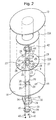
- Fig. 2 is an exploded perspective view of the airbag and the airbag system.
- the airbag 10 includes a front panel 12, a rear panel 14, a first inner panel 22A, and a second inner panel 22B, which are each made of a circular woven fabric.
- the front panel 12 and the rear panel 14 have an equal diameter, of which the outer peripheries are stitched together into a bag shape with a seam 15 such as thread.
- the stitched portion has a ring shape along the outer peripheries of the front panel 12 and the rear panel 14.
- the rear panel 14 has an inflator (gas generator) opening 16 and vent holes 18.
- the inflator opening 16 is disposed in the center of the rear panel 14.
- bolt-insertion holes 20 are provided.
- the airbag 10 includes the first inner panel 22A and the second inner panel 22B therein.
- the first and second inner panel 22A and 22B are centered at the identical point with the front panel 12 and the rear panel 14, of which the outer peripheries are stitched together with a seam 23B such as thread.
- the inner periphery of the first inner panel 22A adjacent to the front panel 12 (the periphery of the first inner panel 22A adjacent to the end, with the airbag 10 in an inflated state) is sawn on the midpoint between the center and the periphery of the front panel 12 with a seam 23A such as thread.
- the center of the second inner panel 22B adjacent to the rear panel 14 (the portion of the second inner panel 22B adjacent to the rear end thereof, with the airbag 10 in an inflated state) has an inflator opening 24 centered at the identical point with the inflator opening 16 of the rear panel 14.
- the openings 16 and 24 have substantially an equal diameter.
- bolt-insertion holes 26, which agree with the bolt-insertion holes 20 of the rear panel 14, are provided.
- the second inner panel 22B has inner vent holes 28 closer to the outer periphery and, as communicating portions, communication holes 27 closer to the inner periphery for communicating the first chamber 1 and the second chamber 2 with each other.
- the inner vent holes 28 may be provided in the first inner panel 22A.
- the periphery of the inflator opening 24 of the second inner panel is superposed on the periphery of the inflator opening 16 of the rear panel 14 and on the periphery of an inflator-mounting hole 32 of a retainer 30.
- the peripheries of the inflator openings 24 and 16 are fixed to the retainer 30 through the bolt-insertion holes 26 and 20, respectively.
- the periphery of the inflator opening 24 of the second inner panel 22B connects to the periphery of the inflator opening 16 of the rear panel 14; the outer peripheries of the first and second inner panels 22A and 22B connect with each other; and the inner periphery of the first inner panel 22A connects with the front panel 12.
- the first and second inner panels 22A and 22B partition the interior of the airbag 10 into a central first chamber 1 and a second chamber 2 around the first chamber 1.
- the first chamber 1 is inside the inner panels 22A and 22B.
- the communication holes 27 are provided on the extension of the gas emitting direction of an inflator 36, to be described later, which is disposed in the first chamber 1 through the inflator openings 16 and 24, or at the position facing gas ports 36a of the inflator 36.
- this embodiment includes four communication holes 27 and four inner vent holes 28 at equal intervals in the circumferential direction of the airbag 10.
- the communication holes 27 and the inner vent holes 28 are circumferentially out of phase relative to the center of the airbag 10.
- Reinforcing patches may be attached to the peripheries of the openings 16 and 24, the communication holes 27, and the vent holes 18 and 28.
- the retainer 30 for mounting the airbag 10 has the inflator-mounting hole 32 in the center, around which bolt-insertion holes 35 are provided.
- the inflator 36 is substantially cylindrical and has the gas ports 36a around the side circumference at the axial end. This embodiment includes four gas ports 36a at equal intervals in the circumferential direction of the inflator 36.
- the inflator 36 emits a jet of gas radially from the gas ports 36a.
- a flange 38 for fixing the inflator 36 projects from the side circumference of the axial middle of the inflator 36 (close to the rear end relative to the gas ports 36a).
- the flange 38 has bolt-insertion holes 40.
- the end of the inflator 36 is fitted in the inflator-mounting hole 32 of the retainer 30.
- the peripheries of the respective inflator openings 16 and 24 of the rear panel 14 and the second inner panel 22B are retained to the periphery of the inflator-mounting hole 32 of the retainer 30 with a ferrule 42.
- the end of the inflator 36 fitted in the inflator-mounting hole 32 is inserted into the first chamber 1 through the inflator openings 16 and 24.
- the gas ports 36a at the end of the inflator 36 face the communication holes 27 of the second inner panel 22B.
- the inflator 36 is activated to emit a jet of gas into the airbag 10.
- the airbag 10 is inflated by the gas, opening the module cover 48 to deploy in the vehicle cabin, thereby protecting the driver-seat occupant.
- the airbag 10 is constructed such that the communication holes 27, which communicate the first chamber 1 and the second chamber 2 together, are disposed on the extension of the gas-emitting direction of the inflator 36 disposed in the first chamber 1, or to face the gas ports 36a of the inflator 36. Accordingly, upon activation of the inflator 36, gas is ejected from the inflator 36 to the communication holes 27. Thus the gas from the inflator 36 is also supplied directly into the second chamber 2 through the communication holes 27, as shown in Fig. 1, so that the second chamber 2 inflates early.
- the inner vent holes 28 are provided in the second inner panel.
- the inner vent holes 28 may be provided in the first inner panel 22A.
- the inner vent holes 28 may be provided in both of the first inner panel 22A and the second inner panel 22B.
- the other structures of the airbag 10A are the same as those of the airbag 10 in Figs. 1 and 2.
- the above embodiment includes four gas ports 36a and four communication holes 27, the number is not limited to four.
- the communication holes 27 are disposed on the extension of the gas-emitting direction of all of the gas ports 36a of the inflator 36, the communication holes 27 may be disposed only on the extension of the gas-emitting direction of part of the gas ports 36a. Alternatively, there may be communication holes disposed off the extension of the gas ports 36a so that they do not face the gas ports 36a.
- the shape of the communication holes 27 may be other than that in the drawing.
- the area of the opening of the communication holes 27 is selected depending on the internal volume of the second chamber 2, so that there is no particular limit. Also the shape of the panels may be other than that in the drawing.
- the airbag may include a rectifier cloth in the first chamber 1, for guiding the gas from the inflator into the communication holes.
- Fig. 4 is an exploded perspective view of an airbag 10B and an airbag system according to another embodiment.
- Fig. 5 is a cross sectional view taken along line V-V of Fig. 4.
- the airbag 10B includes the front panel 12 and the rear panel 14, which construct the outer shell, and the first inner panel 22A and a second inner panel 22C for partitioning the interior of the airbag 10B into the central first chamber 1 and the peripheral second chamber 2.
- the second inner panel 22C in this embodiment includes a ring-shaped center portion 70, which is interposed on the periphery of the inflator opening 16 of the rear panel 14, and four strap portions 71 projecting radially from the outer periphery of the center portion 70.
- the strap portions 71 are spaced equidistantly around the center portion 70.
- Bolt-insertion holes 73 are provided around a center opening (inflator opening) 72 of the center portion 70, for the stud bolts 44 of the ferrule 42 to pass through.
- the front panel 12, the rear panel 14, and the first inner panel 22A are circular also in this embodiment.
- the peripheries of the front panel 12 and the rear panel 14 are stitched together with the seam 15.
- the inner periphery of the first inner panel 22A is sawn on the midpoint between the center and the periphery of the front panel 12.
- the inner vent holes 28 are provided in the first inner panel 22A.
- the center portion 70 of the second inner panel 22C is centered at the identical point with the first inner panel 22A.
- the end of each strap portion 71 is sawn on the outer periphery of the first inner panel 22A with a seam 23C.
- the ends of the strap portions 71 are spaced equidistantly around the first inner panel 22A.
- the clearances between the strap portions 71 serve as communicating portions 74 for communicating the first chamber 1 and the second chamber 2 together.
- the center portion 70 of the second inner panel 22C is superposed on the periphery of the inflator opening 16 of the rear panel 14 and fixed to the periphery of the inflator-mounting hole 32 of the retainer 30 with the ferrule 42.
- the end (gas ejecting portion) of the inflator 36 fitted in the inflator-mounting hole 32 is inserted into the first chamber 1 through the inflator openings 16 and 72.
- four gas ports 36a are disposed equidistantly around the side circumference at end of the inflator 36.
- the gas ports 36a face the communicating portions 74.
- the other structures of the airbag 10B and an airbag system including the airbag 10B are the same as those of the embodiment in Figs. 1 and 2.
- the same reference numerals in Figs. 4 and 5 as those of Figs. 1 and 2 denote the same components.
- the gas ports 36a of the inflator 36 disposed in the first chamber 1 face the communicating portions 74 that communicate the first chamber 1 and the second chamber 2 with each other. Accordingly, upon activation of the inflator 36, a jet of gas is emitted from the gas ports 36a toward the communicating portions 74. The gas from the inflator 36 is therefore supplied directly also to the second chamber 2 through the communicating portions 74. Thus the second chamber 2 inflates early.
- the second inner panel 22C is made of a cross-shaped woven fabric including the center portion 70 which lies on the periphery of the inflator opening 16 of the rear panel 14 and the four strap portions 71 extending radially from the center portion 70. Accordingly, the entire area is smaller than that made of a circular fabric. This reduces the usage of the fabric for the panel to reduce material cost, thus resulting in resource saving.
- the number of the strap portions 71 is not necessarily four but is selected as appropriate depending on the number of the gas ports of the inflator 36.
- the first inner panel of the invention may not necessarily be circular.
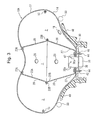
- Fig. 6(a) is a plan view of a first inner panel according to another embodiment.
- Fig. 6(b) is an exploded perspective view of the first inner panel and a second inner panel.
- the first inner panel 22D of this embodiment is made of a cross-shaped woven fabric including a center portion 80 which is connected to a front panel (not shown) and four strap portions 81 extending radially from the center portion 80.
- the fabric is formed into a bottomless bag, shown in Fig. 6(b), by folding the belt-like portions 81 from the base toward a rear panel (not shown) and stitching the sides of the adjacent strap portions 81 together.
- Reference numeral 82 denotes the seam of the stitch.
- the space inside the bag-shaped first inner panel 22D serves as a first chamber.
- the ends of the strap portions 71 of the second inner panel 22C are sawn on the peripheries at the ends of the strap portions 81.
- the second inner panel 22C is the same as that of the embodiment in Figs. 4 and 5.
- the first inner panel 22D is made of a cross-shaped woven fabric including the center portion 80 and the four strap portions 81 extending radially from the center portion 80. Accordingly, the entire area is smaller than that made of a circular fabric. This reduces the usage of the fabric for the panel to reduce material cost, thus resulting in resource saving.
- the number of the strap portions 81 is not necessarily four but may be three or five.
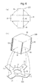
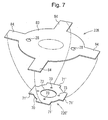
- Fig. 7 is an exploded perspective view of a first inner panel 22E and a second inner panel 22C' with such a structure.
- the first inner panel 22E of this embodiment includes a circular main body 83 whose center portion is connected with a front panel (not shown) and four strap portions 84 projecting radially from the outer periphery of the main body 83.
- the strap portions 84 are spaced equidistantly around the main body 83.
- the alternate long and two short dashes line around the center portion of the main body 83 indicates a stitch line for connecting the center portion of the main body 83 and the front panel.
- the inner vent holes 28 are provided in the vicinity of the midpoint between the center and the outer periphery of the main body 83.
- the second inner panel 22C' includes the ring-shaped center portion 70 superposed on the periphery of the inflator opening of a rear panel (not shown) and four strap portions 71' projecting radially from the outer periphery of the center portion 70.
- the strap portions 71' are spaced equidistantly around the center portion 70.
- the strap portions 71' of this embodiment are shorter than the strap portions 71 of the embodiment in Figs. 4 to 6.
- the strap portions 84 of the first inner panel 22E and the strap portions 71' of the second inner panel 22C' are joined together by stitching or the like, so that the clearances between the joined strap portions 71' and 84 serve as communicating portions for communicating the first chamber and the second chamber together.
- the first chamber may have a guide member for guiding the gas from the inflator into the communicating portions (openings).
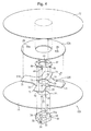
- Fig. 8 is a cross sectional view of an airbag system, showing an example of the guide member.
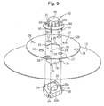
- Fig. 9 is an exploded perspective view of the essential parts of the airbag system.
- the first chamber 1 of the airbag 10 includes a guide member 60 for guiding gas from an inflator 36A into the communication holes 27 for the first chamber 1 and the second chamber 2.
- the airbag 10 is the same as the airbag 10 of Figs. 1 and 2.
- the inflator 36A of this embodiment has the gas ports 36a around the side circumference at the end thereof. The end is disposed in the first chamber 1 through the inflator openings 16 and 24 (refer to Fig. 9). Also the inflator 36A emits a jet of gas radially from the gas ports 36a. However, the gas ports 36a and the communication holes 27 of this embodiment are out of phase relative to the center of the airbag; the communication holes 27 are not on the extension in the gas-emitting direction of the gas ports 36a.
- the other structures of the inflator 36A are the same as those of the airbag system of Figs. 1 and 2.
- the guide member 60 includes a substantially ring-shaped enclosure wall 61 that encloses the side circumference of the end of the inflator 36A, a top plate 62 that closes the front end (the occupant side) of the enclosure wall 61, gas discharge ports 63 provided in the enclosure wall 61, a ferrule 64 disposed around the rear end of the enclosure wall 61, and stud bolts 65 projecting backwardly from the ferrule 64.
- the space enclosed by the enclosure wall 61 and the top plate 62 serves as a gas receiving chamber 66 for receiving the gas from the inflator 36A.
- the gas discharge ports 63 are spaced equidistantly around the enclosure wall 61, through which the gas in the gas receiving chamber 66 flows out radially.
- the guide member 60 is fixed to the retainer 30 together with the second inner panel 22B, the rear panel 14, and the inflator 36A in such a way that the ferrule 64 is superposed on the periphery of the inflator opening 24 of the second inner panel 22B from within the first chamber 1 and the stud bolts 65 are passed through the respective bolt-insertion holes of the second inner panel 22B, the rear panel 14, the retainer 30, and the flange 38 of the inflator 36A, on the ends of which nuts 46 are fastened.
- the end of the inflator 36A is disposed in the gas receiving chamber 66 through the respective inflator openings of the retainer 30, the rear panel 14, and the second inner panel 22B.
- the guide member 60 is disposed in such a manner that the communication holes 27 are placed on the extension of the gas-discharging direction of part of the gas discharge ports 63 and the panel portion of the second inner panel 22B is placed on the extension of the gas-discharging direction of the remaining gas discharge ports 63, with the airbag 10 in an inflated state.
- the guide member 60 is made of metal or heat-resistant synthetic resin; however, it is not limited to that.
- the gas from the inflator 36A can be introduced into the communication holes 27 by the guide member 60, so that the gas can be supplied also to the second chamber 2, even when the communication holes 27 for communicating the first chamber 1 and the second chamber 2 with each other are not disposed on the extension of the gas-emitting direction of the gas ports 36a of the inflator 36A.
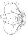
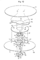
- Fig. 10 is a cross sectional view of an airbag system 10C, showing another example of the guide member.
- the interior of the first chamber 1 of the airbag 10C is partitioned by a partitioning inner panel 90 serving as a guide member into a small chamber 91 adjacent to the inflator 36 and a large chamber 92 adjacent to the front panel 12.
- the airbag 10C has the same structure as the airbag 10 of Figs. 1 and 2, except that the partitioning inner panel 90 is provided.
- the partitioning inner panel 90 of this embodiment is made of a circular woven fabric and disposed inside the second inner panel 22B (inside the first chamber 1), at the identical point with the second inner panel 22B, the periphery of which is sawn on the midpoint between the inner periphery (adjacent to the inflator opening 24) and the outer periphery of the second inner panel 22B with a seam 93.
- the inner vent holes 28 are disposed closer to the outer periphery of the second inner panel 22B, while the communication holes 27 for the second chamber 2 are disposed closer to the inner periphery.
- the periphery of the partitioning inner panel 90 is sawn on the portion between the inner vent holes 28 and the communication holes 27, i.e. the partitioning inner panel 90 is connected to the second inner panel 22B.
- the small chamber 91 is formed between the partitioning inner panel 90 and the inflator 36, while the large chamber 92 is formed between the partitioning inner panel 90 and the front panel 12.
- the communication holes 27 face the small chamber 91, while the inner vent holes 28 face the large chamber 92.
- the partitioning inner panel 90 has gas discharge openings 94 for discharging gas from the small chamber 91 into the large chamber 92.
- the shape, arrangement, opening area of the gas discharge openings 94 are selected depending on the internal volume of the large chamber 92 and are not particularly limited.
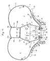
- Fig. 11 is a cross sectional view of an airbag and an airbag system according to another embodiment.
- Fig. 12 is an exploded perspective view of the airbag and airbag system.
- the first inner panel 22A in the airbag 10D is connected to the front panel 12 comprising a side facing the occupant of the airbag 10D via a tether member 100.
- the tether member 100 has a base portion 101 sewn at the central portion of the first inner panel 22A (the end portion adjacent to the occupant of the first inner panel 22A in the inflated state of the airbag 10D) and two tether portions 102 and 102 being strap-shaped or belt-shaped and projecting from the base portion 101.
- the base portion 101 is made of a circular woven fabric, of which the diameter is smaller than that of the first inner panel 22A.
- the base portion 101 is centered at the identical point with the first inner panel 22A on the occupant side, of which the outer periphery is stitched together to the first inner panel 22A with a seam 23D.
- Each tether portion 102 is connected to the outer periphery of the base portion 101 at one end, and stitched together to the front panel 12 near the center portion with a seam 103 at the other end. In this embodiment, as shown in Fig. 12, these two tether portion 102 and 102 are disposed across the center of the base portion 101 from each other.
- the construction of the tether 100 is not limited to this; the tether portion 102 may be provided with one or more than three tether portions.
- the tether portion 102 may be panel-shaped or tubular.
- the tether portion 102 may be provided separately from the base portion 101.
- the tether portion 102 may be directly connected to the first inner panel 22A at the one end with the base portion 101 omitted.
- the other structures of the airbag 10D are the same as those of the airbag 10B in Figs. 4 and 5.
- the same reference numerals in Figs. 11 and 12 as those of Figs. 4 and 5 denote the same components.
- the first inner panel 22A is connected to the front panel 12 via the tether portion 102. This facilitates the adjustment of the thickness of the inflated airbag 10D by adjusting the length of the tether portion 102.
- the embodiment of the Fig. 11 and 12 shows the connecting structure of the first inner panel 22A and the front panel 12 in the embodiment of Fig. 4 and 5 by the tether member 100.
- the inner panel 22A, 22D and 22E in the other embodiments described above can be connected to the front panel 12 via a tether member.
- drawings of these connecting structures are omitted.
- the periphery of the inflator opening of the second inner panel is retained to the periphery of the inflator opening of the rear panel with a ferrule.
- the periphery of the inflator opening of the second inner panel may be sawn on the periphery of the inflator opening of the rear panel.
- the peripheries of the inflator openings are reinforced by each other.
- reinforcement patch cloth may be attached to the peripheries of the openings.
Landscapes
- Engineering & Computer Science (AREA)
- Mechanical Engineering (AREA)
- Air Bags (AREA)
Abstract
Description
The airbag includes a front panel disposed on the occupant side and a rear panel disposed opposite to the occupant, the peripheries of the front panel and the rear panel being connected with each other. The rear panel has an opening for the gas generator in the center. An inner panel is disposed for partitioning the interior of the airbag into a central first chamber and a second chamber enclosing the first chamber. The inner panel has an opening in the center, the opening centered at the identical point with the opening of the rear panel. The periphery of the inner panel adjacent to the end is connected with a midpoint between the center and the periphery of the front panel. The inner panel has communicating portions for communicating the first chamber and the second chamber with each other. The first chamber includes a guide member for guiding the gas from the gas generator toward the communicating portions.
Claims (10)
- An airbag (10; 10A; 10B; 10C; 10D) inflated by gas from a gas generator (36), the airbag (10; 10A; 10B; 10C; 10D) comprising:a front panel (12) disposed on the occupant side and a rear panel (14) disposed opposite to the occupant, the peripheries of the front panel (12) and the rear panel (14) being connected with each other,wherein the rear panel (14) has an opening (16) for the gas generator (36) in the center, andan inner panel (22A, 22B; 22C; 22C'; 22D; 22E) for partitioning the interior of the airbag into a central first chamber (1) and a second chamber enclosing the first chamber (2),wherein the inner panel (22A, 22B; 22C; 22C'; 22D; 22E) has an opening (24) in the center, the opening (24) centered at the identical point with the opening (16) of the rear panel, andthe periphery of the inner panel (22A, 22B; 22C; 22C'; 22D; 22E) adjacent to the end is connected with a midpoint between the center and the periphery of the front panel (12);wherein the inner panel comprises a first inner panel (22A; 22D; 22E) adjacent to the front panel (12) and a second inner panel (22B; 22C; 22C') adjacent to the rear panel;the rear end of the first inner panel (22A; 22D; 22E) is connected to the front end of the second inner panel (22B; 22C; 22C');the second inner panel (22B; 22C; 22C') has communicating portions (27; 74) for communicating the first chamber (1) and the second chamber (2) with each other; andthe communicating portions (27; 74) are disposed on the extension of the gas-emitting direction of the gas generator (36), with the airbag (10; 10A; 10B; 10C; 10D) in an inflated state.
- The airbag according to Claim 1,
wherein the rear panel (14) has a vent hole (18) and the inner panel has an inner vent hole (28) for communicating the first chamber (1) and the second chamber (2) with each other. - The airbag according to Claim 1 or 2, wherein the first inner panel (22A; 22D; 22E) is connected to the front panel via a tether member (100).
- An airbag system comprising an airbag (10; 10A; 10B; 10C; 10D) and a gas generator (36) including a gas port (36a),
wherein at least the end of the gas generator (36) is disposed in the airbag (10; 10A; 10B; 10C; 10D) and the gas port is disposed in the airbag, and wherein:the airbag (10; 10A; 10B; 10C; 10D) is the airbag according to any one of Claims 1 to 3; andthe communicating portions (27; 74) are disposed on the extension of the gas-emitting direction of the gas generator, with the airbag (10; 10A; 10B; 10C; 10D) in an inflated state. - An airbag system comprising an airbag (10; 10A; 10B; 10C) and a gas generator (36) including a gas port (36a),
wherein at least the end of the gas generator (36) is disposed in the airbag (10; 10A; 10B; 10C; 10D) and the gas port (36a) is disposed in the airbag (10; 10A; 10B; 10C; 10D), and wherein:wherein the rear panel (14) has an opening (16) for the gas generator (36) in the center,the airbag (10; 10A; 10B; 10C; 10D) comprises a front panel (12) disposed on the occupant side and a rear panel (14) disposed opposite to the occupant, the peripheries of the front panel (12) and the rear panel (14) being connected with each other,
an inner panel (22A, 22B; 22C; 22C'; 22D; 22E) is disposed for partitioning the interior of the airbag (10) into a central first chamber (1) and a second chamber (2) enclosing the first chamber (1),
the inner panel (22A, 22B; 22C; 22C'; 22D; 22E) has an opening (24) in the center, the opening (24) centered at the identical point with the opening of the rear panel (14), and
the periphery of the inner panel (22A, 22B; 22C; 22C'; 22D; 22E) adjacent to the end is connected with a midpoint between the center and the periphery of the front panel (12);
wherein the inner panel has communicating portions (27) for communicating the first chamber (1) and the second chamber (2) with each other, and
the first chamber (1) includes a guide member (60; 90) for guiding the gas from the gas generator (36) toward the communicating portions (27). - The airbag system according to Claim 5, wherein:the guide member (60; 90) comprises a gas receiving chamber (66) for receiving the gas from the gas generator (36) and a gas discharge opening (63) for discharging the gas in the gas receiving chamber (66) into the first chamber (1) ; andthe communicating portions (27) are disposed on the extension of the gas discharging direction of the gas discharge opening (63), with the airbag (10) in an inflated state.
- The airbag system according to Claim 5 or 6, wherein:the airbag (10) and the gas generator (36) are mounted to a retainer (30); andthe guide member (60) encloses the end of the gas generator (36) and is mounted to the retainer (30) with a mounting member common to the gas generator (36).
- The airbag system according to Claim 5, wherein:the guide member (60; 90) is a partitioning inner panel (90) for partitioning the interior of the first chamber (1) into a small chamber (91) adjacent to the gas generator (36) and a large chamber (92) adjacent to the front panel (12);the partitioning inner panel (90) has a discharging portion (94) for discharging the gas from the small chamber (91) into the large chamber (92); andthe communicating portions (27) face the small chamber.
- The airbag system according to Claim 8, wherein the partitioning inner panel (90) is connected to the inner panel (22A, 22B).
- The airbag system according to one of Claims 5 to 9, wherein the rear panel (14) has a vent hole (18); and
the inner panel (22A, 22B) has an inner vent hole (28) for communicating the first chamber (1) and the second chamber (2) with each other.
Applications Claiming Priority (8)
| Application Number | Priority Date | Filing Date | Title |
|---|---|---|---|
| JP2004064554 | 2004-03-08 | ||
| JP2004064554 | 2004-03-08 | ||
| JP2004259943 | 2004-09-07 | ||
| JP2004259943 | 2004-09-07 | ||
| JP2004320852 | 2004-11-04 | ||
| JP2004320852 | 2004-11-04 | ||
| JP2005053671A JP4604765B2 (en) | 2004-03-08 | 2005-02-28 | Airbag device |
| JP2005053671 | 2005-02-28 |
Publications (2)
| Publication Number | Publication Date |
|---|---|
| EP1574403A1 true EP1574403A1 (en) | 2005-09-14 |
| EP1574403B1 EP1574403B1 (en) | 2009-04-29 |
Family
ID=34831318
Family Applications (1)
| Application Number | Title | Priority Date | Filing Date |
|---|---|---|---|
| EP05004696A Expired - Fee Related EP1574403B1 (en) | 2004-03-08 | 2005-03-03 | Airbag with inner walls |
Country Status (5)
| Country | Link |
|---|---|
| US (1) | US7334812B2 (en) |
| EP (1) | EP1574403B1 (en) |
| JP (1) | JP4604765B2 (en) |
| CN (1) | CN100500481C (en) |
| DE (1) | DE602005014155D1 (en) |
Cited By (4)
| Publication number | Priority date | Publication date | Assignee | Title |
|---|---|---|---|---|
| EP1676756A1 (en) * | 2004-12-28 | 2006-07-05 | Takata Corporation | Airbag apparatus |
| EP1676755A1 (en) * | 2004-12-28 | 2006-07-05 | Takata Corporation | Airbag and airbag module |
| EP1676754A1 (en) * | 2004-12-28 | 2006-07-05 | Takata Corporation | Airbag and airbag module |
| EP1712431A3 (en) * | 2005-04-15 | 2007-01-24 | Takata Corporation | Airbag and airbag apparatus |
Families Citing this family (27)
| Publication number | Priority date | Publication date | Assignee | Title |
|---|---|---|---|---|
| JP4935064B2 (en) * | 2005-01-11 | 2012-05-23 | タカタ株式会社 | Air bag and air bag device |
| JP4595520B2 (en) * | 2004-12-15 | 2010-12-08 | タカタ株式会社 | Airbag device |
| JP4807004B2 (en) * | 2004-12-22 | 2011-11-02 | タカタ株式会社 | Airbag device |
| US7931299B2 (en) * | 2005-09-21 | 2011-04-26 | Tk Holdings, Inc. | Low risk deployment airbag cushion |
| US8020889B2 (en) * | 2005-09-21 | 2011-09-20 | Tk Holdings, Inc. | Passive airbag venting |
| US7942440B2 (en) * | 2005-12-22 | 2011-05-17 | Autoliv Asp, Inc. | Channel and diffuser airbag |
| JP2007331658A (en) * | 2006-06-16 | 2007-12-27 | Takata Corp | Airbag and airbag device |
| US7988194B2 (en) * | 2006-09-20 | 2011-08-02 | Tk Holdings Inc. | Airbag apparatus |
| US7878537B2 (en) * | 2006-09-20 | 2011-02-01 | Tk Holdings Inc. | Airbag cushion |
| KR100778589B1 (en) * | 2006-11-07 | 2007-11-22 | 현대자동차주식회사 | The driver air bag for a vehicle |
| JP4940312B2 (en) * | 2007-02-14 | 2012-05-30 | オートリブ ディベロップメント エービー | Automotive airbag |
| JP5127343B2 (en) * | 2007-07-26 | 2013-01-23 | タカタ株式会社 | Air bag and air bag device |
| EP2174843B1 (en) * | 2008-10-13 | 2013-06-19 | Autoliv Development AB | Air-bag |
| WO2010122835A1 (en) * | 2009-04-24 | 2010-10-28 | 本田技研工業株式会社 | Airbag device |
| WO2010151651A2 (en) * | 2009-06-24 | 2010-12-29 | Shape Corp. | Energy absorber with double-acting crush lobes |
| JP2011126307A (en) * | 2009-12-15 | 2011-06-30 | Takata Corp | Air bag device |
| US8789846B2 (en) | 2012-03-07 | 2014-07-29 | Tk Holdings Inc. | Airbag device |
| KR101460726B1 (en) * | 2013-07-03 | 2014-11-12 | 현대모비스 주식회사 | An airbag of a vehicle |
| US9162645B2 (en) | 2013-12-20 | 2015-10-20 | Ford Global Technologies, Llc | High pressure airbag for oblique impact modes |
| CN110509885B (en) * | 2014-01-21 | 2022-02-25 | 均胜安全系统收购有限责任公司 | Passenger side airbag |
| DE112015000442T5 (en) | 2014-01-21 | 2016-12-01 | Tk Holdings Inc. | Passenger side airbag |
| US9561774B2 (en) | 2014-04-24 | 2017-02-07 | Ford Global Technologies, Llc | Winged driver airbag |
| US9969349B2 (en) | 2014-04-24 | 2018-05-15 | Ford Global Technologies, Llc | Passenger airbag with extended base |
| US9713998B2 (en) | 2014-04-24 | 2017-07-25 | Ford Global Technologies, Llc | Corrugated passenger airbag |
| CN109204206B (en) * | 2018-08-21 | 2021-07-20 | 孙龙 | Recyclable external automatic pop-up type safety isolation air bag system for automobile |
| US11198411B2 (en) * | 2019-04-18 | 2021-12-14 | Autoliv Asp. Inc. | Energy-absorbing airbag diffusers and related airbag assemblies |
| EP4063200A4 (en) * | 2019-11-22 | 2023-12-06 | Autoliv Development AB | Driver seat airbag device for vehicle and method for manufacturing same |
Citations (5)
| Publication number | Priority date | Publication date | Assignee | Title |
|---|---|---|---|---|
| US5249824A (en) * | 1991-11-19 | 1993-10-05 | Trw Inc. | Air bag structure and method of forming |
| US5464250A (en) * | 1992-06-17 | 1995-11-07 | Kabushiki Kaisha Tokai-Rika-Denki-Seisakusho | Bag suitable for use in an air bag apparatus and method of manufacturing the same |
| US5607183A (en) * | 1992-09-14 | 1997-03-04 | Teijin Limited | Air bag provided with reinforcing belts |
| EP1044855A2 (en) * | 1999-04-13 | 2000-10-18 | Toyota Jidosha Kabushiki Kaisha | Air bag device |
| EP1279566A1 (en) * | 2001-07-24 | 2003-01-29 | Takata Corporation | Airbag with three compartments |
Family Cites Families (33)
| Publication number | Priority date | Publication date | Assignee | Title |
|---|---|---|---|---|
| JPS5090030A (en) * | 1973-12-14 | 1975-07-18 | ||
| JPH0513656Y2 (en) * | 1985-05-07 | 1993-04-12 | ||
| JP2631300B2 (en) | 1988-03-29 | 1997-07-16 | タカタ株式会社 | Airbag |
| JPH01311930A (en) * | 1988-06-09 | 1989-12-15 | Nippon Plast Co Ltd | Driver protecting device for car or the like |
| JPH0322480U (en) | 1989-07-13 | 1991-03-07 | ||
| JP2879233B2 (en) * | 1989-12-27 | 1999-04-05 | 池田物産 株式会社 | Airbag device |
| JPH03281460A (en) * | 1990-03-29 | 1991-12-12 | Mazda Motor Corp | Air bag device for automobile |
| JP3039068B2 (en) * | 1991-12-04 | 2000-05-08 | タカタ株式会社 | Air bag |
| JP2900098B2 (en) | 1991-12-27 | 1999-06-02 | 日産自動車株式会社 | Automotive airbag device |
| JPH08104195A (en) * | 1994-09-30 | 1996-04-23 | Toyo Tire & Rubber Co Ltd | Air bag for vehicle |
| JPH07232607A (en) | 1994-02-24 | 1995-09-05 | Toyo Tire & Rubber Co Ltd | Air bag for vehicle and its manufacture |
| JPH09220995A (en) * | 1996-02-14 | 1997-08-26 | Takata Kk | Air bag and its forming method |
| JPH09315246A (en) | 1996-05-31 | 1997-12-09 | Sensor Technol Kk | Air bag unfolding method for occupant protective device, air bag thereof and manufacture of the air bag |
| JPH11255063A (en) * | 1998-03-13 | 1999-09-21 | Takata Kk | Air bag and air bag device |
| US6086092A (en) * | 1998-07-07 | 2000-07-11 | Trw Vehicle Safety Systems Inc. | Inflatable vehicle occupant protection device |
| DE29818946U1 (en) * | 1998-10-23 | 1999-02-25 | Trw Repa Gmbh | Airbag for a vehicle occupant restraint system |
| US6254121B1 (en) * | 1998-12-14 | 2001-07-03 | Breed Automotive Technology, Inc. | Chambered driver side air bag and module attachment method |
| DE19858690A1 (en) * | 1998-12-18 | 2000-06-21 | Delphi Automotive Systems Gmbh | Airbag |
| US6962363B2 (en) * | 2000-07-07 | 2005-11-08 | Milliken & Company | Multiple chamber airbags and methods |
| JP4560984B2 (en) * | 2001-04-13 | 2010-10-13 | タカタ株式会社 | Airbag device for driver's seat |
| JP4660971B2 (en) * | 2001-06-05 | 2011-03-30 | タカタ株式会社 | Air bag and air bag device |
| JP2003170796A (en) * | 2001-12-06 | 2003-06-17 | Takata Corp | Airbag |
| JP4048894B2 (en) | 2002-09-27 | 2008-02-20 | マツダ株式会社 | Airbag device for vehicle |
| US7111866B2 (en) * | 2003-01-23 | 2006-09-26 | Takata Corporation | Airbag and airbag system |
| JP4935064B2 (en) * | 2005-01-11 | 2012-05-23 | タカタ株式会社 | Air bag and air bag device |
| JP2006117153A (en) * | 2004-10-22 | 2006-05-11 | Takata Corp | Airbag and airbag device |
| JP4807004B2 (en) * | 2004-12-22 | 2011-11-02 | タカタ株式会社 | Airbag device |
| JP4534762B2 (en) * | 2004-12-28 | 2010-09-01 | タカタ株式会社 | Airbag device for driver's seat |
| JP4687105B2 (en) * | 2004-12-28 | 2011-05-25 | タカタ株式会社 | Airbag device |
| JP2006248511A (en) * | 2005-02-09 | 2006-09-21 | Takata Corp | Airbag and airbag device |
| JP4735021B2 (en) * | 2005-04-26 | 2011-07-27 | タカタ株式会社 | Airbag device |
| JP2007055577A (en) * | 2005-07-29 | 2007-03-08 | Takata Corp | Airbag and airbag device |
| EP1757495B1 (en) * | 2005-08-24 | 2008-05-21 | Takata Corporation | Airbag and airbag apparatus |
-
2005
- 2005-02-28 JP JP2005053671A patent/JP4604765B2/en not_active Expired - Fee Related
- 2005-03-03 DE DE602005014155T patent/DE602005014155D1/en active Active
- 2005-03-03 EP EP05004696A patent/EP1574403B1/en not_active Expired - Fee Related
- 2005-03-08 US US11/075,162 patent/US7334812B2/en not_active Expired - Fee Related
- 2005-03-08 CN CNB2005100544919A patent/CN100500481C/en not_active Expired - Fee Related
Patent Citations (5)
| Publication number | Priority date | Publication date | Assignee | Title |
|---|---|---|---|---|
| US5249824A (en) * | 1991-11-19 | 1993-10-05 | Trw Inc. | Air bag structure and method of forming |
| US5464250A (en) * | 1992-06-17 | 1995-11-07 | Kabushiki Kaisha Tokai-Rika-Denki-Seisakusho | Bag suitable for use in an air bag apparatus and method of manufacturing the same |
| US5607183A (en) * | 1992-09-14 | 1997-03-04 | Teijin Limited | Air bag provided with reinforcing belts |
| EP1044855A2 (en) * | 1999-04-13 | 2000-10-18 | Toyota Jidosha Kabushiki Kaisha | Air bag device |
| EP1279566A1 (en) * | 2001-07-24 | 2003-01-29 | Takata Corporation | Airbag with three compartments |
Cited By (5)
| Publication number | Priority date | Publication date | Assignee | Title |
|---|---|---|---|---|
| EP1676756A1 (en) * | 2004-12-28 | 2006-07-05 | Takata Corporation | Airbag apparatus |
| EP1676755A1 (en) * | 2004-12-28 | 2006-07-05 | Takata Corporation | Airbag and airbag module |
| EP1676754A1 (en) * | 2004-12-28 | 2006-07-05 | Takata Corporation | Airbag and airbag module |
| US7416209B2 (en) | 2004-12-28 | 2008-08-26 | Takata Corporation | Airbag apparatus |
| EP1712431A3 (en) * | 2005-04-15 | 2007-01-24 | Takata Corporation | Airbag and airbag apparatus |
Also Published As
| Publication number | Publication date |
|---|---|
| DE602005014155D1 (en) | 2009-06-10 |
| US20050194769A1 (en) | 2005-09-08 |
| JP4604765B2 (en) | 2011-01-05 |
| CN1666910A (en) | 2005-09-14 |
| EP1574403B1 (en) | 2009-04-29 |
| JP2006151350A (en) | 2006-06-15 |
| US7334812B2 (en) | 2008-02-26 |
| CN100500481C (en) | 2009-06-17 |
Similar Documents
| Publication | Publication Date | Title |
|---|---|---|
| EP1574403B1 (en) | Airbag with inner walls | |
| US6834884B2 (en) | Airbag | |
| EP1442944B1 (en) | Airbag and airbag apparatus | |
| US7673899B2 (en) | Airbag and airbag apparatus | |
| EP1747951B1 (en) | Airbag and airbag apparatus | |
| US7281734B2 (en) | Airbag and airbag system | |
| JP2006306149A (en) | Airbag, and airbag device | |
| JP5478332B2 (en) | Airbag device | |
| US20060138761A1 (en) | Airbag and airbag apparatus | |
| EP1547876B1 (en) | Airbag and airbag system | |
| US20060091649A1 (en) | Airbag and airbag device | |
| US7416209B2 (en) | Airbag apparatus | |
| US20060138752A1 (en) | Airbag and airbag apparatus | |
| EP1864869B1 (en) | Airbag and airbag system |
Legal Events
| Date | Code | Title | Description |
|---|---|---|---|
| PUAI | Public reference made under article 153(3) epc to a published international application that has entered the european phase |
Free format text: ORIGINAL CODE: 0009012 |
|
| AK | Designated contracting states |
Kind code of ref document: A1 Designated state(s): AT BE BG CH CY CZ DE DK EE ES FI FR GB GR HU IE IS IT LI LT LU MC NL PL PT RO SE SI SK TR |
|
| AX | Request for extension of the european patent |
Extension state: AL BA HR LV MK YU |
|
| 17P | Request for examination filed |
Effective date: 20060209 |
|
| AKX | Designation fees paid |
Designated state(s): DE FR GB SE |
|
| GRAP | Despatch of communication of intention to grant a patent |
Free format text: ORIGINAL CODE: EPIDOSNIGR1 |
|
| GRAS | Grant fee paid |
Free format text: ORIGINAL CODE: EPIDOSNIGR3 |
|
| RIN1 | Information on inventor provided before grant (corrected) |
Inventor name: ABE, KAZUHIROC/O TAKATA CORPORATION |
|
| GRAA | (expected) grant |
Free format text: ORIGINAL CODE: 0009210 |
|
| AK | Designated contracting states |
Kind code of ref document: B1 Designated state(s): DE FR GB SE |
|
| REG | Reference to a national code |
Ref country code: GB Ref legal event code: FG4D |
|
| REF | Corresponds to: |
Ref document number: 602005014155 Country of ref document: DE Date of ref document: 20090610 Kind code of ref document: P |
|
| PG25 | Lapsed in a contracting state [announced via postgrant information from national office to epo] |
Ref country code: SE Free format text: LAPSE BECAUSE OF FAILURE TO SUBMIT A TRANSLATION OF THE DESCRIPTION OR TO PAY THE FEE WITHIN THE PRESCRIBED TIME-LIMIT Effective date: 20090729 |
|
| PLBE | No opposition filed within time limit |
Free format text: ORIGINAL CODE: 0009261 |
|
| STAA | Information on the status of an ep patent application or granted ep patent |
Free format text: STATUS: NO OPPOSITION FILED WITHIN TIME LIMIT |
|
| 26N | No opposition filed |
Effective date: 20100201 |
|
| REG | Reference to a national code |
Ref country code: FR Ref legal event code: ST Effective date: 20101130 |
|
| PG25 | Lapsed in a contracting state [announced via postgrant information from national office to epo] |
Ref country code: FR Free format text: LAPSE BECAUSE OF NON-PAYMENT OF DUE FEES Effective date: 20100331 |
|
| PGFP | Annual fee paid to national office [announced via postgrant information from national office to epo] |
Ref country code: GB Payment date: 20130228 Year of fee payment: 9 |
|
| GBPC | Gb: european patent ceased through non-payment of renewal fee |
Effective date: 20140303 |
|
| PG25 | Lapsed in a contracting state [announced via postgrant information from national office to epo] |
Ref country code: GB Free format text: LAPSE BECAUSE OF NON-PAYMENT OF DUE FEES Effective date: 20140303 |
|
| REG | Reference to a national code |
Ref country code: DE Ref legal event code: R082 Ref document number: 602005014155 Country of ref document: DE Representative=s name: KRAUS & WEISERT PATENTANWAELTE PARTGMBB, DE Ref country code: DE Ref legal event code: R081 Ref document number: 602005014155 Country of ref document: DE Owner name: JOYSON SAFETY SYSTEMS JAPAN K.K., JP Free format text: FORMER OWNER: TAKATA CORP., TOKIO/TOKYO, JP |
|
| PGFP | Annual fee paid to national office [announced via postgrant information from national office to epo] |
Ref country code: DE Payment date: 20180322 Year of fee payment: 14 |
|
| REG | Reference to a national code |
Ref country code: DE Ref legal event code: R119 Ref document number: 602005014155 Country of ref document: DE |
|
| PG25 | Lapsed in a contracting state [announced via postgrant information from national office to epo] |
Ref country code: DE Free format text: LAPSE BECAUSE OF NON-PAYMENT OF DUE FEES Effective date: 20191001 |