EP1574278A2 - TIG welding method and welded structure by the same - Google Patents
TIG welding method and welded structure by the same Download PDFInfo
- Publication number
- EP1574278A2 EP1574278A2 EP05002315A EP05002315A EP1574278A2 EP 1574278 A2 EP1574278 A2 EP 1574278A2 EP 05002315 A EP05002315 A EP 05002315A EP 05002315 A EP05002315 A EP 05002315A EP 1574278 A2 EP1574278 A2 EP 1574278A2
- Authority
- EP
- European Patent Office
- Prior art keywords
- melting point
- point member
- tig welding
- bus bar
- low melting
- Prior art date
- Legal status (The legal status is an assumption and is not a legal conclusion. Google has not performed a legal analysis and makes no representation as to the accuracy of the status listed.)
- Withdrawn
Links
Images




Classifications
-
- B—PERFORMING OPERATIONS; TRANSPORTING
- B23—MACHINE TOOLS; METAL-WORKING NOT OTHERWISE PROVIDED FOR
- B23K—SOLDERING OR UNSOLDERING; WELDING; CLADDING OR PLATING BY SOLDERING OR WELDING; CUTTING BY APPLYING HEAT LOCALLY, e.g. FLAME CUTTING; WORKING BY LASER BEAM
- B23K9/00—Arc welding or cutting
- B23K9/23—Arc welding or cutting taking account of the properties of the materials to be welded
- B23K9/232—Arc welding or cutting taking account of the properties of the materials to be welded of different metals
-
- B—PERFORMING OPERATIONS; TRANSPORTING
- B23—MACHINE TOOLS; METAL-WORKING NOT OTHERWISE PROVIDED FOR
- B23K—SOLDERING OR UNSOLDERING; WELDING; CLADDING OR PLATING BY SOLDERING OR WELDING; CUTTING BY APPLYING HEAT LOCALLY, e.g. FLAME CUTTING; WORKING BY LASER BEAM
- B23K9/00—Arc welding or cutting
- B23K9/23—Arc welding or cutting taking account of the properties of the materials to be welded
-
- B—PERFORMING OPERATIONS; TRANSPORTING
- B23—MACHINE TOOLS; METAL-WORKING NOT OTHERWISE PROVIDED FOR
- B23K—SOLDERING OR UNSOLDERING; WELDING; CLADDING OR PLATING BY SOLDERING OR WELDING; CUTTING BY APPLYING HEAT LOCALLY, e.g. FLAME CUTTING; WORKING BY LASER BEAM
- B23K2103/00—Materials to be soldered, welded or cut
- B23K2103/08—Non-ferrous metals or alloys
- B23K2103/12—Copper or alloys thereof
Definitions
- the present invention relates to TIG (Tungsten Insertion Gas) welding method for TIG welding a high melting point member and a low melting point member, where melting points of two members are different from each other, and welded structure by the method.
- TIG Tungsten Insertion Gas
- TIG welding method two members are overlapped each other, and welding arc is generated with TIG welding torch facing and being adjacent to the overlapped portion of two members. Two members melt coincidentally and mix each other, then solidifying to form a bead.
- the present invention has been devised with considering the aforementioned circumstance, and aims to provide TIG welding method and welded structure that are capable of enhancing, by comparison to conventional method and structure, welding strength between members whose melting points differ each other.
- the present invention provides TIG welding method for welding a high melting point member and a low melting point member whose melting point are different from each other.
- a TIG welding torch is set in more adjacent to the high melting point member than the low melting point member to generate arc.
- the present invention provides welded structure by TIG welding a high melting point member and a low melting point member whose melting point are different from each other.
- the high melting point member protrudes from a side surface or an end surface of the low melting point member, and the protrusion is melt to form a bead to cover the bonding portion between the high melting point member and the low melting point member.
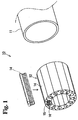
- a motor 10 shown in Fig. 1 is a brush-less motor for an electric power steering system incorporated in an automobile, and has a stator core 12 in a cylindrical housing 11.
- the stator core 12 has a structure being dividable into a number of core bodies in the circumferential direction.
- a coil 15 is wounded around each core body 14 in the longitudinal direction (axial direction).
- Both ends of a wire 16 configuring the coil 15 are arranged at one end (upper end in Fig. 2) of the stator core 12, and penetrate a ring-shaped bus-bar holder 20.
- a number of first bus bars 30 are held in the bus-bar holder 20 with insulated each other.
- Protrusions of the first bus bar 30 are directed to the inner periphery of the cylindrical housing 11, and each of protrusions is welded to one end portion of the associated wire 16.
- wires 16 configuring the coils 15 are, at the other ends thereof, electrically connected one another to construct a three-phase motor circuit.
- a tip end portion of the first bus bar 30 protrudes from the bus-bar holder 20 toward upper direction in Fig. 2, with forming tongue pieces 39.
- a connector 51 is attached to a periphery surface of the cylindrical housing 11, and accommodates three second bus bars 40 by way of insert forming.
- a tip end portion of the second bus bar 40 protrudes from a inner periphery surface of the cylindrical housing 11 toward inner space of the same, and is welded to the tip end portion (tongue piece 39) of the first bus bar 30 protruding from the bus-bar holder 20 (with reference to Fig. 4 (B)).
- the first bus bar 30 is made of tough pitch copper as the 'high melting point member' of the present invention.
- the second bus bar 40 is made of copper-zinc alloy as the 'low melting point member' of the present invention.
- 'high melting point' and 'low melting point' indicates relative relationship between two members. When there are two members whose melting point differs each other, the member having relatively high melting point is designated as 'high melting point', and member having relatively low melting point is designated as 'low melting point'.
- the present embodiment embodies the invention in a welding portion between the first bus bar 30 and the second bus bar 40.
- Fig. 4 (A) shows the state before the first bus bar 30 and the second bus bar 40 are welded together.
- the second bus bar 40 is formed with a slit 46 which breaching the tip end portion thereof. Width of the slit 46 is approximately same with the thickness of the first bus bar 30. Depth of the slit 46 is approximately same with the width of the tongue piece 39 of the first bus bar 30.
- protrusions 43 formed at both sides of the slit 46 of the second bus bar 40 are line-symmetric about the slit 46.
- the taper surface 45 which become closer to the slit 46 side as approaching to the tip end thereof.
- the tongue piece 39 of the first bus bar 30 is inserted into the bottom of the slit 46, and held to protrude from the upper surface of the second bus bar 40.
- the length of the protrusion is approximately one to three times of the thickness of the second bus bar 40.
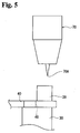
- the first bus bar 30 and the second bus bar 40 configured as described above are welded together by way of TIG welding. Specifically, as shown in Fig. 5, a tip end portion 70A of a TIG welding torch 70 is positioned adjacently to the tongue piece 39 of the first bus bar 30, then generating arc. Therefore, the first bus bar 30 (the high melting potion member) which is adjacent to the TIG welding torch 70 receives much more heat in comparison with the second bus bar 40 (the low melting point member). Accordingly, the first bus bar 30 and the second bus bar 40 melt properly. In addition, since protrusions 43 of the second bus bar 40 are formed into tapered shape, tip end sides of protrusions 43 are melted surely.
- first bus bar 30 and the second bus bar 40 are mixed in the melted state.
- a bead 50 is formed at a crossing portion between the first bus bar 30 and the second bus bar 40 as shown in Fig. 4 (B), then integrally connecting the first bus bar 30 and the second bus bar 40.
- the wire 16 is made of tough pitch copper same as the first bus bar 30, the wire 16 and the first bus bar 30 are welded together by way of conventional welding, i.e. welding between members having same melting point, to connect integrally.
- the TIG welding torch 70 is positioned at closer to the first bus bar 30 than the second bus bar 40, then generating arc.
- the second bus bar 40 as the low melting point member is prevented from over heated, generation of blow hole is suppressed, insufficient melting of the first bus bar 30 as the high melting point member is diminished, and welding strength is improved in comparison with the conventional method and structure.
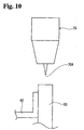
- blow holes occupied less area in the first test piece 85 subjected to the TIG welding method of the embodiment than that in the second or the third test piece 86 or 87 subjected to the other TIG welding method.
- the first test piece 85 indicated less than approximate1 % of incidence of blow hole
- the second test piece 86 indicated approximate 5 % of incidence
- the third test piece 87 indicated approximate 5 %.
- a TIG welding torch 70 is set in more adjacent to a first bus bar 30 than a second bus bar 40 to generate arc. Consequently, the second bus bar 40 serving as a low melting point member is prevented from over heated, occurrence of blow holes is suppressed, and inadequate melting of the first bus bar 30 serving as a high melting point member is improved, resulting in enhancement of welding strength.
- the method is applicable to electrical equipment, especially to a motor, provided with a vehicle.
Landscapes
- Engineering & Computer Science (AREA)
- Chemical & Material Sciences (AREA)
- Materials Engineering (AREA)
- Physics & Mathematics (AREA)
- Plasma & Fusion (AREA)
- Mechanical Engineering (AREA)
- Arc Welding In General (AREA)
- Butt Welding And Welding Of Specific Article (AREA)
- Manufacture Of Motors, Generators (AREA)
Abstract
Description
Claims (11)
- A TIG welding method for welding a high melting point member and a low melting point member whose melting point are different from each other, wherein a TIG welding torch is set in more adjacent to the high melting point member than the low melting point member to generate arc.
- A TIG welding method according to claim 1, wherein the high melting point member and the low melting point member are mainly composed of same metal.
- A TIG welding method according to claim 2, wherein both of the high melting point member and the low melting point member are mainly composed of iron.
- A TIG welding method according to claim 2, wherein both of the high melting point member and the low melting point member are mainly composed of aluminum.
- A TIG welding method according to claim 2, wherein both of the high melting point member and the low melting point member are mainly composed of copper.
- A TIG welding method according to claim 5, wherein the high melting point member is made of tough pitch copper and the low melting point member is made of copper-zinc alloy.
- A TIG welding method according to any one of claim 1 to 6, wherein the low melting point member is a bus bar having a slit splitting a tip end thereof, and a tip end of the high melting point member is inserted into the slit.
- A welded structure by TIG welding a high melting point member and a low melting point member whose melting point are different from each other, wherein
the high melting point member protrudes from a side surface or an end surface of the low melting point member, and
the protrusion is melted to form a bead to cover the bonding portion between the high melting point member and the low melting point member. - A welded structure by TIG welding according to claim 8, wherein the high melting point member and the low melting point member are provided in the electrical equipment for a vehicle.
- A welded structure by TIG welding according to claim 9, wherein the electrical equipment is a motor applied to a power steering apparatus, and the high melting point member and the low melting point member are bus bars welded together.
- A welded structure by TIG welding according to any one of claims 8 to 10 wherein,
the low melting point member is bus bar having a slit splitting a tip end thereof,
a tip end the of the high melting point member is inserted into the slit to protrudes from a side surface of the bus bar, then melting to form a bead.
Applications Claiming Priority (2)
| Application Number | Priority Date | Filing Date | Title |
|---|---|---|---|
| JP2004043938 | 2004-02-20 | ||
| JP2004043938A JP2005230869A (en) | 2004-02-20 | 2004-02-20 | Tig welding method for different kinds of metals and its welding structure |
Publications (2)
| Publication Number | Publication Date |
|---|---|
| EP1574278A2 true EP1574278A2 (en) | 2005-09-14 |
| EP1574278A3 EP1574278A3 (en) | 2007-07-04 |
Family
ID=34824489
Family Applications (1)
| Application Number | Title | Priority Date | Filing Date |
|---|---|---|---|
| EP05002315A Withdrawn EP1574278A3 (en) | 2004-02-20 | 2005-02-03 | TIG welding method and welded structure by the same |
Country Status (4)
| Country | Link |
|---|---|
| US (1) | US20050184040A1 (en) |
| EP (1) | EP1574278A3 (en) |
| JP (1) | JP2005230869A (en) |
| CN (1) | CN1658438A (en) |
Cited By (1)
| Publication number | Priority date | Publication date | Assignee | Title |
|---|---|---|---|---|
| EP1814687B1 (en) * | 2004-11-15 | 2012-04-11 | Valeo Electronique et Systèmes de Liaison | Method for laser welding without addition of material, and electrical device formed using said method |
Families Citing this family (4)
| Publication number | Priority date | Publication date | Assignee | Title |
|---|---|---|---|---|
| KR20110055255A (en) * | 2009-11-19 | 2011-05-25 | 에스비리모티브 주식회사 | Bus bar and battery module with same |
| JP2017035736A (en) * | 2016-09-27 | 2017-02-16 | 日立金属株式会社 | Manufacturing method of capsule for hip and manufacturing method of sintered body |
| CN115065203B (en) * | 2022-08-16 | 2022-11-11 | 成都微精电机股份公司 | Relative position adjusting structure and method for motor and rotary encoder |
| CN119016833B (en) * | 2024-10-18 | 2025-03-11 | 天合光能股份有限公司 | Solar cell welding method and solar cell |
Family Cites Families (12)
| Publication number | Priority date | Publication date | Assignee | Title |
|---|---|---|---|---|
| DE761478C (en) * | 1940-10-23 | 1954-10-25 | Siemens & Halske A G | Process for welding bodies of different heat capacities or melting temperatures with the help of a welding pen |
| DE1182510B (en) * | 1961-09-25 | 1964-11-26 | Csf | Process for the thermal connection of two sheets having parallel edges |
| FR2037729A5 (en) * | 1969-03-07 | 1970-12-31 | Mitsubishi Heavy Ind Ltd | |
| JPS5893583A (en) * | 1981-11-27 | 1983-06-03 | Hitachi Ltd | How to join aluminum and iron |
| FR2574175B1 (en) * | 1984-12-04 | 1989-02-10 | Sanden Corp | ALUMINUM HEAT EXCHANGER |
| ATE99749T1 (en) * | 1989-12-09 | 1994-01-15 | Escher Wyss Gmbh | PROCESS FOR MANUFACTURING A WIRE SCREEN. |
| US6288008B1 (en) * | 1991-07-04 | 2001-09-11 | Matsumoto Kokan Co., Ltd. | Metallic catalyst support and production method thereof |
| FR2732630B1 (en) * | 1995-04-04 | 1997-06-20 | Lorraine Laminage | EDGE-TO-EDGE WELDING METHOD OF TWO METAL BLANKS |
| JP3333728B2 (en) * | 1997-12-25 | 2002-10-15 | 東海ゴム工業株式会社 | Bush mounting member and method of manufacturing the same |
| EP1130745A3 (en) * | 2000-03-02 | 2003-12-10 | Calsonic Kansei Corporation | Brushless motor |
| DE10195150D2 (en) * | 2000-12-01 | 2004-01-22 | Fronius Internat Gmbh Pettenba | Method of joining metal objects |
| JP3593102B2 (en) * | 2002-01-08 | 2004-11-24 | 三菱電機株式会社 | Electric power steering device |
-
2004
- 2004-02-20 JP JP2004043938A patent/JP2005230869A/en not_active Withdrawn
-
2005
- 2005-02-03 EP EP05002315A patent/EP1574278A3/en not_active Withdrawn
- 2005-02-15 US US11/057,210 patent/US20050184040A1/en not_active Abandoned
- 2005-02-18 CN CN2005100095623A patent/CN1658438A/en active Pending
Cited By (1)
| Publication number | Priority date | Publication date | Assignee | Title |
|---|---|---|---|---|
| EP1814687B1 (en) * | 2004-11-15 | 2012-04-11 | Valeo Electronique et Systèmes de Liaison | Method for laser welding without addition of material, and electrical device formed using said method |
Also Published As
| Publication number | Publication date |
|---|---|
| EP1574278A3 (en) | 2007-07-04 |
| CN1658438A (en) | 2005-08-24 |
| JP2005230869A (en) | 2005-09-02 |
| US20050184040A1 (en) | 2005-08-25 |
Similar Documents
| Publication | Publication Date | Title |
|---|---|---|
| EP1187299B1 (en) | Stator of dynamo-electric machine and manufacturing method therefor | |
| CN103368304B (en) | On-vehicle motor and employ the driven steering device of this on-vehicle motor | |
| JP5207533B2 (en) | Composite fusible link, fuse box and manufacturing method thereof | |
| US10666110B2 (en) | Bus bar unit | |
| JP5335265B2 (en) | Electric motor | |
| CN103947082B (en) | Rotary electric machine and stator manufacturing method | |
| JP2018120678A (en) | Electromagnetic shield parts and wire harness | |
| CN108448773A (en) | Bus bar unit and motor | |
| CN102449888A (en) | Stator structure and method for producing stator | |
| JP4321400B2 (en) | Bus bar | |
| CN101867098A (en) | Aluminium conductor terminal device and manufacture method thereof | |
| JP2005216827A (en) | Electric wire terminal terminal and manufacturing method thereof | |
| US20050184040A1 (en) | TIG welding method and welded structure made by the same | |
| JP6139742B1 (en) | How to connect the power feeding unit | |
| JP2004064954A (en) | BUS BAR WELDING STRUCTURE AND ITS WELDING METHOD | |
| WO2021166670A1 (en) | Terminal module in rotary electric machine | |
| JP3977138B2 (en) | Rotating electric machine | |
| US12348096B2 (en) | Coil having segment conductors welded with a welded metal portion | |
| JP3384743B2 (en) | Laser welding structure of bus bar | |
| JP7769929B2 (en) | inductor | |
| JP3325204B2 (en) | Laser welding structure of bus bar | |
| JP2005184959A (en) | Electric motor lead frame and power distribution parts using the same | |
| JP2021132518A (en) | Stator manufacturing method and terminals | |
| JP5710420B2 (en) | Busbar equipment | |
| US20260081494A1 (en) | Hairpin configuration of electric machine |
Legal Events
| Date | Code | Title | Description |
|---|---|---|---|
| PUAI | Public reference made under article 153(3) epc to a published international application that has entered the european phase |
Free format text: ORIGINAL CODE: 0009012 |
|
| AK | Designated contracting states |
Kind code of ref document: A2 Designated state(s): AT BE BG CH CY CZ DE DK EE ES FI FR GB GR HU IE IS IT LI LT LU MC NL PL PT RO SE SI SK TR |
|
| AX | Request for extension of the european patent |
Extension state: AL BA HR LV MK YU |
|
| RAP1 | Party data changed (applicant data changed or rights of an application transferred) |
Owner name: JTEKT CORPORATION |
|
| RIN1 | Information on inventor provided before grant (corrected) |
Inventor name: KUWABARA, HIROFUMIC/O JTEKT CORP. Inventor name: YAMAMOTO, TETSUJIC/O JTEKT CORP. |
|
| PUAL | Search report despatched |
Free format text: ORIGINAL CODE: 0009013 |
|
| AK | Designated contracting states |
Kind code of ref document: A3 Designated state(s): AT BE BG CH CY CZ DE DK EE ES FI FR GB GR HU IE IS IT LI LT LU MC NL PL PT RO SE SI SK TR |
|
| AX | Request for extension of the european patent |
Extension state: AL BA HR LV MK YU |
|
| RIC1 | Information provided on ipc code assigned before grant |
Ipc: B23K 103/12 20060101ALN20070529BHEP Ipc: H02K 11/00 20060101ALI20070529BHEP Ipc: B23K 9/23 20060101AFI20050720BHEP |
|
| 17P | Request for examination filed |
Effective date: 20080103 |
|
| AKX | Designation fees paid |
Designated state(s): DE FR GB |
|
| STAA | Information on the status of an ep patent application or granted ep patent |
Free format text: STATUS: THE APPLICATION HAS BEEN WITHDRAWN |
|
| 18W | Application withdrawn |
Effective date: 20080917 |