EP1573282B1 - Device for determining and/or monitoring at least one physical variable comprising a piezo drive for exciting and detecting oscillations - Google Patents
Device for determining and/or monitoring at least one physical variable comprising a piezo drive for exciting and detecting oscillations Download PDFInfo
- Publication number
- EP1573282B1 EP1573282B1 EP03782331.7A EP03782331A EP1573282B1 EP 1573282 B1 EP1573282 B1 EP 1573282B1 EP 03782331 A EP03782331 A EP 03782331A EP 1573282 B1 EP1573282 B1 EP 1573282B1
- Authority
- EP
- European Patent Office
- Prior art keywords
- piezoelectric element
- segments
- stack
- base unit
- unit
- Prior art date
- Legal status (The legal status is an assumption and is not a legal conclusion. Google has not performed a legal analysis and makes no representation as to the accuracy of the status listed.)
- Expired - Lifetime
Links
- 230000010355 oscillation Effects 0.000 title claims description 9
- 238000012544 monitoring process Methods 0.000 title claims description 4
- 230000010287 polarization Effects 0.000 claims description 32
- 239000000853 adhesive Substances 0.000 claims description 12
- 230000001070 adhesive effect Effects 0.000 claims description 12
- 238000003466 welding Methods 0.000 claims description 6
- 229910000679 solder Inorganic materials 0.000 claims description 5
- 230000010358 mechanical oscillation Effects 0.000 claims 12
- 239000000725 suspension Substances 0.000 claims 1
- 238000005452 bending Methods 0.000 description 7
- 238000013461 design Methods 0.000 description 7
- 239000012528 membrane Substances 0.000 description 7
- 230000000694 effects Effects 0.000 description 4
- 230000003534 oscillatory effect Effects 0.000 description 4
- 238000005476 soldering Methods 0.000 description 4
- 238000010276 construction Methods 0.000 description 3
- 230000005284 excitation Effects 0.000 description 3
- 238000000034 method Methods 0.000 description 3
- 239000013590 bulk material Substances 0.000 description 2
- 238000009434 installation Methods 0.000 description 2
- 230000005540 biological transmission Effects 0.000 description 1
- 230000000903 blocking effect Effects 0.000 description 1
- 238000005352 clarification Methods 0.000 description 1
- 238000005520 cutting process Methods 0.000 description 1
- 238000011161 development Methods 0.000 description 1
- 238000009826 distribution Methods 0.000 description 1
- 238000005553 drilling Methods 0.000 description 1
- 239000002360 explosive Substances 0.000 description 1
- 238000005259 measurement Methods 0.000 description 1
- 238000002360 preparation method Methods 0.000 description 1
- 238000012545 processing Methods 0.000 description 1
Images


Classifications
-
- G—PHYSICS
- G01—MEASURING; TESTING
- G01F—MEASURING VOLUME, VOLUME FLOW, MASS FLOW OR LIQUID LEVEL; METERING BY VOLUME
- G01F23/00—Indicating or measuring liquid level or level of fluent solid material, e.g. indicating in terms of volume or indicating by means of an alarm
- G01F23/22—Indicating or measuring liquid level or level of fluent solid material, e.g. indicating in terms of volume or indicating by means of an alarm by measuring physical variables, other than linear dimensions, pressure or weight, dependent on the level to be measured, e.g. by difference of heat transfer of steam or water
- G01F23/28—Indicating or measuring liquid level or level of fluent solid material, e.g. indicating in terms of volume or indicating by means of an alarm by measuring physical variables, other than linear dimensions, pressure or weight, dependent on the level to be measured, e.g. by difference of heat transfer of steam or water by measuring the variations of parameters of electromagnetic or acoustic waves applied directly to the liquid or fluent solid material
- G01F23/296—Acoustic waves
- G01F23/2966—Acoustic waves making use of acoustical resonance or standing waves
- G01F23/2967—Acoustic waves making use of acoustical resonance or standing waves for discrete levels
-
- G—PHYSICS
- G01—MEASURING; TESTING
- G01F—MEASURING VOLUME, VOLUME FLOW, MASS FLOW OR LIQUID LEVEL; METERING BY VOLUME
- G01F23/00—Indicating or measuring liquid level or level of fluent solid material, e.g. indicating in terms of volume or indicating by means of an alarm
- G01F23/22—Indicating or measuring liquid level or level of fluent solid material, e.g. indicating in terms of volume or indicating by means of an alarm by measuring physical variables, other than linear dimensions, pressure or weight, dependent on the level to be measured, e.g. by difference of heat transfer of steam or water
- G01F23/28—Indicating or measuring liquid level or level of fluent solid material, e.g. indicating in terms of volume or indicating by means of an alarm by measuring physical variables, other than linear dimensions, pressure or weight, dependent on the level to be measured, e.g. by difference of heat transfer of steam or water by measuring the variations of parameters of electromagnetic or acoustic waves applied directly to the liquid or fluent solid material
- G01F23/296—Acoustic waves
- G01F23/2968—Transducers specially adapted for acoustic level indicators
-
- G—PHYSICS
- G01—MEASURING; TESTING
- G01N—INVESTIGATING OR ANALYSING MATERIALS BY DETERMINING THEIR CHEMICAL OR PHYSICAL PROPERTIES
- G01N2291/00—Indexing codes associated with group G01N29/00
- G01N2291/02—Indexing codes associated with the analysed material
- G01N2291/028—Material parameters
- G01N2291/02836—Flow rate, liquid level
Definitions
- the invention relates to a device for determining and / or monitoring at least one physical variable of a medium having at least one mechanically oscillatable unit and at least one drive / receiving unit, wherein the drive / receiving unit excites the oscillatable unit to vibrate, or wherein the Drive / receiving unit receives the vibrations of the oscillatory unit.
- EP 0 875 739 discloses the preamble of claim 1.
- a disadvantage of these patents is that there are special requirements with respect to the design of the vibrating rod and the attachment of the piezoelectric element. Furthermore, the vibrating rod is not directly excited to tilt oscillations, but to bending vibrations, which lead by the geometry of the vibrating rod and by the attachment of the piezoelectric element on the vibrating rod to tilting vibrations.
- a piezo-electric element is applied to the oscillatable unit or on a suitable membrane, for example with an adhesive bond. If a voltage is applied to the piezoelectric element, then there is a change in length. However, since the piezoelectric element is connected to the oscillatable unit because the oscillatable unit does not undergo linear expansion, it causes the piezoelectric element and the vibratable unit to bend. By the application of an AC voltage thus results in a bending vibration. Due to the special configuration of the oscillatable unit, it must be sensibly ensured that there is a preferred direction for this oscillation. Furthermore, the piezoelectric element must be connected to the oscillatory unit so that the change in length is transmitted substantially in the bending movement. At the same time, the connection must also be such that it still holds in the bent state. A preferred method is the connection by means of an adhesive. However, adhesives usually only allow use up to a certain temperature.
- the object of the invention is to excite a device capable of vibrating mechanically with a device, or to detect its vibrations, wherein the device should be as simple and inexpensive as possible. This also in terms of installation and in terms of the design of the other components required for the application. Furthermore, the device should enable the oscillations to be generated directly or to be received directly, without the detour having to be taken over another form of movement.
- the object is achieved by the invention such that in the drive and receiving unit at least one piezo-electric element is provided which has at least one outer surface which consists of at least two segments with different polarization, wherein the polarization directions are substantially opposite to each other in that the mechanically oscillatable unit is connected directly or indirectly to the outer surface, so that the mechanically oscillatable unit is excited to move, or so that a movement of the mechanically oscillatable unit is received, the movement each consisting of at least two different force components , which are substantially opposite to each other, and wherein the force components are tension and pressure, and the movement is a tilting movement or a rotational movement.
- a great advantage of the invention is that a tilting movement is generated. It is no longer a bending movement whose implementation is realized in a tilting moment by the special attachment of the piezo drive to a specially shaped rod. This makes it possible that the mechanically oscillatable unit have virtually any shape and that the Drive space-saving and easy to install. Furthermore, eliminates the cost of elaborate processing and preparation.
- the physical quantity to be determined or monitored may be the level, the viscosity, the density or the temperature of a medium.
- An advantageous implementation includes that the segments are designed symmetrically to each other. For example, it can be two halves of a cylinder. The idea is that the segments are virtually shorted together so that, for example, the effects of forces on the side of the piezo drive act, compensate. At the same time pyroelectric effects are prevented, whereby the drive can also be used in potentially explosive areas.
- the piezoelectric element is at least one stack consisting of piezoelectric elements.
- the thinner piezoelectric elements have the advantage of being less expensive than, for example, higher cylinders.
- these elements can be combined to match stacks.
- the piezoelectric elements are arranged in the stack such that at least two segments of the same polarization are opposite each other and substantially cover each other, and that results in at least one outer surface, which consists of at least two segments with different polarization , Likewise, when the piezo-electric elements in the stack face each other such that the segments substantially occupy the same force component, and when there is at least one outer surface having at least two segments that apply different force components, and receive. This corresponds in each case to an arrangement in which the piezoelectric elements in the stack are mechanically connected in series and electrically in parallel.
- At least one electrically conductive member is provided between them, so that the segments of the outer surfaces of the piezoelectric elements in the stack are shorted together and / or that the outer surfaces of the piezoelectric elements, the in the stack opposite each other, are shorted to each other.
- a connecting device may be provided, so that the piezoelectric elements are under compressive stress in the stack.
- Other fastening options are adhesive, soldering and / or welding layers between the elements and / or a screw connection.
- the geometric configuration of the piezoelectric element is hardly subject to any limitation. It can be disc-shaped or ring-shaped, round or angular. It is only important that an outer surface results with at least two segments with different polarization or that results in an outer surface that can produce at least two different force components.
- the piezoelectric element bores for fixing and / or for the implementation of electrical components, e.g. Wires to install.
- At least one electrode is provided on the outer surface of the piezoelectric element, which is conductively connected to at least two segments with different polarization, or which is connected to two segments that exert or receive different force components on the mechanically oscillatable unit.
- At least one first electrode and at least one second electrode are provided on the outer surface of the piezoelectric element, wherein the first electrode at least with a first Segment of a first polarization is conductively connected, and wherein the second electrode is conductively connected to at least a second segment of a second polarization, wherein the first polarization of the first segment is different from the second polarization of the second segment, and wherein the first and second electrodes are electrically connected together.
- the first electrode is conductively connected to at least a first segment, which exerts and receives a first force component
- the second electrode is conductively connected to at least a second segment, which exerts and receives a second force component, wherein the first force component of the first segment is different than the second force component of the second segment, and wherein the first and second electrodes are electrically connected together.
- different segments of the piezoelectric element reach the same signal, these segments due to the signal with react different force components on the mechanically oscillatable unit, or vice versa, the signal that results from the different force components, are derived suitable.
- at least one adhesive, soldering and / or welding layer and / or screw connection is expediently provided.
- a useful embodiment includes providing at least two piezoelectric elements or at least two stacks consisting of piezoelectric elements or at least one piezoelectric element and at least one stack, wherein a piezoelectric element or a stack is used for this purpose vibratory unit to excite vibrations, and wherein another piezo-electric element or another stack receives the vibrations of the mechanically oscillatable unit.
- one part of the piezo drive serves to excite the vibrations and another part serves to receive the vibrations.
- One possibility is to attach a cutting disc between these two functional sections for mechanical decoupling.
- At least one adhesive, soldering and / or welding layer and / or a screw connection is provided between the piezoelectric element and the mechanically oscillatable unit. This connection serves to fix the oscillating unit to the drive and at the same time to ensure power transmission.
- the mechanically oscillatable unit is a tuning fork or a monobloc, the tuning fork or the monobloc being attached to a base unit. This can for example be done by the mechanically oscillatable unit is attached to a membrane.
- the base unit is usually the housing part, which is fastened to the container in which the medium is located, whose physical size is to be determined and / or monitored.
- One embodiment consists of an inner vibrating rod within an outer tube.
- the inner rod is fixed at one end to a fixing unit in the base unit. This is the fixed end of the inner rod.
- the other end of the inner rod is designed as a free end.
- the piezoelectric element is advantageously mounted within the base unit and thus causes the inner rod, the outer tube or the inner rod and the outer tube to vibrate, or the piezoelectric element receives the corresponding vibrations.
- the piezoelectric element is connected to the fixing element of the inner rod with the inner rod, wherein the piezoelectric element is mounted on the side of the fixing element, which faces the free end of the inner rod or facing away is.
- Another implementation includes providing a second fixing member in the base unit to which the outer tube is fixed.
- the piezoelectric element can also excite the outer tube to vibrate, or receive its vibrations. This is especially important when the outer tube is e.g. is blocked by contact with a bulk material. If, in this case, only the inner rod was caused to vibrate by the construction, then it could be stimulated to vibrate despite the blocking of the outer tube and it could lead to misinterpretation of the measurement results. This misinterpretation is circumvented by also causing the outer tube to vibrate.
- the mechanically oscillatable unit is an inner oscillating rod within an outer tube, the outer tube being fixed at one end to the base unit and capped at the other end, and the inner oscillating rod abutting this cap is attached. It is therefore a one-rod, which has been folded in at one end. In this implementation, it is advisable that the piezoelectric element between the inner rod and the cap is fixed.
- the mechanically oscillatable unit is a single rod with a compensation weight and two mounting points, with one end of the rod inside a base unit. It is useful if the piezoelectric element is attached to the single rod within the base unit behind the compensation weight.
- the base unit may also be, for example, a membrane.
- the following are some ways of fixing the forks on the base unit enumerated. Both forks can be separated at the base unit e.g. fix with individual discs. But you can also fix both forks by a common disc.
- the two forks are fixed within the base unit with a common U-shaped connector.
- two piezoelectric elements are provided in each case, which are each connected to the forks.
- Another development with only one piezoelectric element results when both forks are fixed within the base unit by the transverse part of a common T-shaped connector. Then, the piezoelectric element can be mounted within the longitudinal side of the T-shaped connecting piece between the first and the second fork prong, and only one of the piezo-electric element is sufficient to swing both forks.
- the aforementioned embodiments relate in each case to piezoelectric elements which each had only two segments with different polarizations or with different force components.
- a further embodiment is that four segments with two different polarizations or with two force components are provided on an outer surface of the piezoelectric element, wherein the polarizations or force components of the adjacent segments are each different.
- This piezoelectric element can then be very effectively also apply to a tuning fork with two forks when in each case the segments of the same polarization or the same force component are positioned over the forks.
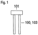
- FIG. 1 shows the components of the device for determining and / or monitoring the physical size of a medium which are treated in the invention: mechanically oscillatable unit 100 and drive / receiving unit 101.
- the example here shows a vibrating fork 103 as a mechanically oscillatable unit 100.
- this is not intended to be limiting represent, since in the further example, rods as mechanically oscillatable units 100 are discussed.
- Fig. 2 and Fig. 3 the construction of an advantageous embodiment of a piezoelectric element 1 is shown.
- a round disc whose outer surface 102 has the two segments 2, 3 whose polarizations are opposite to each other (represented here by plus + and minus -).
- the fact that here and in the following the piezoelectric elements 1 are shown as round is not meant to be a restriction on the general public.
- the geometric configuration of the piezoelectric elements 1 is not subject to any restriction. It may also be, for example, angular disks or the like. act. It should only be ensured that the mechanically oscillatable unit is connected to at least two segments 2, 3 with different polarization, or with different force component.
- Fig. 4 is shown how, for example, a stack 5 of two piezo-electric elements 1 excites a single rod 6 directly to tilting vibrations.
- the stack 5 On a base unit 7, the stack 5 is attached. At and in this stack 5 are three electrically conductive components 8. With the stack 5, a single rod 6 is connected.
- the enlarged section A ( Fig. 4a ) shows the area around the stack 5. If a voltage is applied to the electrically conductive components 8 (the conductive components are not shown because of the overview in the enlarged section), so the stack 5 contracts on one side and expands on the other. Thus acts on the single rod 6 a tensile and a compressive force. These two force components cause the single rod 6 experiences a direct tilting moment. In this case, the tilting movement is carried out in this example in a plane which is perpendicular to the connection plane of stack 5 and 6 single rod. By applying an alternating voltage, the single rod 6 performs a vibration in this plane specified by the geometry.
- FIG. 5 demonstrates how two piezo-electric elements 1 can be arranged, so that a stack 5 results, as in eg Fig. 4 is shown.
- An advantage of the stack 5 is that there is an increase in force, which can produce greater amplitudes than when using thinner piezoelectric elements 1.
- a stack 5 of flat piezoelectric elements - up to a certain height 1 cheaper than a single piezo-electric element 1 of the same height.
- the two piezoelectric elements 1 are arranged so that in each case the segments 2, 3 are opposite with the same polarization, or with the same force component. This can be clarified by the fact that almost two hands clap applause.
- Between the two elements 1 there is an electrically conductive component 9, which fulfills the task of shorting the segments 2, 3 of the elements 1 and the outer surfaces 102 within the stack 5.
- One possibility for the electrically conductive element 9 is, for example, a soldering tag.
- FIG. 6 there is a side view of a stack 5 of two piezoelectric elements 1.
- the polarizations, or force components are indicated here by arrows. Again, the same polarizations, or force components face each other.
- an electrode 8 which is connected to the piezoelectric elements 1 via the connecting elements 10 such as adhesives, solder joints or welds. Alternatively, a device would be possible through which the piezoelectric elements 1 are under compressive stress.
- the two outer surfaces 102 of the stack are two further electrodes 8, which are interconnected. It is changing for operating the stack 5, the signs of the voltage applied to the electrodes 8 voltages each from, so that there is an electrical parallel connection.
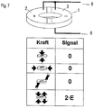
- FIG. 7 a great advantage of the piezoelectric elements of the invention is demonstrated. Shown is such an element 1 with the two electrodes 8. Below is the effect of different forces (indicated by the arrows) illustrates this element. Symmetrical forces cancel each other out in their effect and thus generate no signal. Only a tilting movement on the outside of the piezoelectric element 1 with the segments 2, 3 with opposite polarization results in a signal. The tilting movement is a movement that can be broken down, for example, into the two force components pressure and tension. The signal is referred to here as 2 * E, because the forces acting from above and below on the piezoelectric element 1 result in twice the electrical potential as in the force due to the tilting movement on only one side. Thus, the piezoelectric element is insensitive to most disturbing forces.
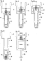
- FIG. 8 to FIG. 12 Examples illustrate how the piezoelectric element 16 with two segments 2, 3 can be used in each case for the vibration excitation of a single rod 6.
- the arrows illustrate the forces acting.
- the piezoelectric elements 16 are pressure and tension;
- the mechanically oscillatable units 6 are the tilting movement resulting from pressure and tension.
- the position of the segments 2, 3 of the piezoelectric element 16 is illustrated by these arrows.
- FIG. 8 to Fig. 10 each show a single rod 6, in which an inner rod 11 is located in an outer tube 12.
- One end of the inner rod 11 is attached as a fixed end 13 to a fixing element, for example to a membrane 14 within the base unit 7.
- the other end of the inner rod 11 is formed as a free end 15.
- the piezoelectric element 16 is connected via a screw 17 on the fixing element 14 with the inner rod 11.
- FIG. 8 is the piezoelectric element 16 on the side of the fixing member 14, which faces the free end 15 of the inner rod 11.
- FIG. 9 he is on the far side.
- the inner rod 11 is excited by the piezoelectric element 16 to vibrate. This can be disadvantageous if the outer tube 12 is blocked by bulk material, for example. In these cases, although the outer tube 12 may not vibrate, the inner tube 11 can still be made to vibrate, resulting in misinterpretation.
- the outer tube 12 is also connected via the attachment unit 18 with the piezoelectric element 16, so that the outer tube 12 can also be excited to vibrate.
- the outer tube 12 is connected at one end 19 to the base unit 7 and closed at the other end 20 with a cap 21.
- the inner rod 11 and the piezoelectric element 16 are fixed via a screw 17.
- it is therefore a single rod 6, whose end has been quasi folded.
- FIG. 12 shows a single rod 22 with an additional weight 23, wherein the single rod 22 has two support points 24 in the base unit 7.
- the piezoelectric element 16 is attached to the end 26 of the single rod 22, which is located within the base unit 7.
- a single rod 6 requires only the overturning moment or torque at its root, i. in the area where it is connected to the base unit 7.
- a more complicated distribution of forces may be required.
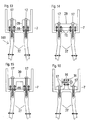
- FIGS. 13 to 16 the application is demonstrated in vibrating forks 103 with two forks 27 as a mechanically oscillating unit.
- FIGS. 13 to 15 two piezoelectric elements-16 are required in each case.
- the design in FIG. 16 only one piezoelectric element needs a 16.
- FIGS. 13 to 16 is first to the piezoelectric Element 16 with two segments 2, 3 thought.
- An application of a multi-segment piezoelectric element 16 would possibly require slight changes in implementation.
- Each forks 27 is connected to the base unit 7 with a screw connection 17 and a separate fixing block 28.
- the configuration of the disc 29 as a common connector is in FIG. 15 extended to a U-shaped connector 30.
- FIG. 16 demonstrates how it is possible to use only one piezo drive 16 for both forks 27.
- For the fork tines 27 are fixed with a T-shaped connector 31, in the longitudinal side of the piezo drive 16 is located, which is fixed with a further screw 17.
- FIGS. 17 to 20 are particularly devoted to the design of a piezoelectric element 37, the four segments 33, 34, 35, 36 has.
- FIG. 17 is the outer surface 102 of a piezoelectric element 32 can be seen, the four segments 33, 34, 35, 36 has.
- the polarizations, or the force components of the segments 33 and 34, or 35 and 36 to be generated and received, are identical in each case.
- the polarizations or force components of adjacent adjacent segments alternate.
- FIG. 18 A particularly effective embodiment of the assembly of two such piezoelectric elements 32 for a stack is in FIG. 18 to find. There are - as in FIG. 4 - Same polarizations, or equal force components opposite each other.
- FIG. 19 demonstrates the use of such a piezoelectric element with four segments 37 in a tuning fork 103 with two forks 27 as a mechanically oscillatable unit 100. These forks 27 are fixed to a diaphragm 40 of the base unit 7. Within the base unit 7, a piezoelectric element with four segments 37 is attached to the membrane 40. In FIG. 20 is shown that the segments with the same polarization (here minus), or with the same force component respectively over the forks 27 are located.
Landscapes
- Physics & Mathematics (AREA)
- Acoustics & Sound (AREA)
- Electromagnetism (AREA)
- Thermal Sciences (AREA)
- Fluid Mechanics (AREA)
- General Physics & Mathematics (AREA)
- General Electrical Machinery Utilizing Piezoelectricity, Electrostriction Or Magnetostriction (AREA)
- Measurement Of Levels Of Liquids Or Fluent Solid Materials (AREA)
- Apparatuses For Generation Of Mechanical Vibrations (AREA)
Description
Die Erfindung bezieht sich auf eine Vorrichtung zur Bestimmung und/oder Überwachung mindestens einer physikalischen Größe eines Mediums mit mindestens einer mechanisch schwingfähigen Einheit und mindestens einer Antriebs-/Empfangseinheit, wobei die Antriebs-/Empfangseinheit die schwingfähige Einheit zu Schwingungen anregt, bzw. wobei die Antriebs-/Empfangseinheit die Schwingungen der schwingfähigen Einheit empfängt.The invention relates to a device for determining and / or monitoring at least one physical variable of a medium having at least one mechanically oscillatable unit and at least one drive / receiving unit, wherein the drive / receiving unit excites the oscillatable unit to vibrate, or wherein the Drive / receiving unit receives the vibrations of the oscillatory unit.
Die Patente
Nachteilig an diesen Patenten ist, dass spezielle Anforderungen bzgl. der Ausgestaltung des Schwingstabs und der Anbringung des piezo-elektrischen Elements bestehen. Weiterhin wird der Schwingstab nicht direkt zu Kippschwingungen angeregt, sondern zu Biegeschwingungen, die durch die Geometrie des Schwingstabs und durch die Anbringung des piezo-elektrischen Elements am Schwingstab zu Kippschwingungen führen.A disadvantage of these patents is that there are special requirements with respect to the design of the vibrating rod and the attachment of the piezoelectric element. Furthermore, the vibrating rod is not directly excited to tilt oscillations, but to bending vibrations, which lead by the geometry of the vibrating rod and by the attachment of the piezoelectric element on the vibrating rod to tilting vibrations.
Das Prinzip dieser Schwingungserregung ist folgendes: Ein piezo-elektrisches Element wird auf der schwingfähigen Einheit oder auf einer passenden Membran aufgebracht, z.B. mit einer Klebeverbindung. Wird eine Spannung an das piezo-elektrische Element angelegt, so kommt es zu einer Längenänderung. Da zwar das piezo-elektrische Element mit der schwingfähigen Einheit verbunden ist, da die schwingfähige Einheit aber keine Längenausdehnung erfährt, führt dies dazu, dass sich das piezo-elektrische Element und die schwingfähige Einheit verbiegen. Durch das Anlegen einer Wechselspannung ergibt sich somit eine Biegeschwingung. Durch die spezielle Ausgestaltung der schwingfähigen Einheit muss sinnvollerweise sichergestellt werden, dass es eine Vorzugsrichtung für diese Schwingung gibt. Weiterhin muss das piezo-elektrische Element so mit der schwingfähigen Einheit verbunden werden, dass die Längenänderung im Wesentlichen in die Biegebewegung übertragen wird. Gleichzeitig muss die Verbindung auch so beschaffen sein, dass sie auch im verbogenen Zustand noch hält. Eine bevorzugte Methode ist die Verbindung mittels eines Klebers. Kleber ermöglichen jedoch meist nur den Einsatz bis zu einer bestimmten Temperatur.The principle of this vibration excitation is the following: A piezo-electric element is applied to the oscillatable unit or on a suitable membrane, for example with an adhesive bond. If a voltage is applied to the piezoelectric element, then there is a change in length. However, since the piezoelectric element is connected to the oscillatable unit because the oscillatable unit does not undergo linear expansion, it causes the piezoelectric element and the vibratable unit to bend. By the application of an AC voltage thus results in a bending vibration. Due to the special configuration of the oscillatable unit, it must be sensibly ensured that there is a preferred direction for this oscillation. Furthermore, the piezoelectric element must be connected to the oscillatory unit so that the change in length is transmitted substantially in the bending movement. At the same time, the connection must also be such that it still holds in the bent state. A preferred method is the connection by means of an adhesive. However, adhesives usually only allow use up to a certain temperature.
Alles in allem ist die Methode über den Umweg der Biegeschwingungen also sehr aufwendig. Es ist eine spezielle Ausgestaltung in Hinsicht auf die Art der Fixierung des piezo-elektrischen Elements und in Hinsicht auf die Geometrie der schwingfähigen Einheit erforderlich. Die bevorzugte Anbringung durch Kleber hat weiterhin das Problem, dass solche Klebstoffe nur bis zu bestimmten Temperaturen einsetzbar sind. Zudem ist es eine prinzipiell unbefriedigende Methode, dass die Kippbewegung der schwingfähigen Einheit nur über den Zwischenschritt der Biegeschwingung erzielt werden kann.All in all, the method over the detour of the bending vibrations so very expensive. It is a special design in terms of the nature of the fixation of the piezoelectric element and in terms of the geometry of the oscillatory unit required. The preferred application by adhesive also has the problem that such adhesives can only be used up to certain temperatures. In addition, it is a principle unsatisfactory method that the tilting movement of the oscillatory unit can only be achieved via the intermediate step of the bending vibration.
Aufgabe der Erfindung ist es, mit einer Vorrichtung eine mechanisch schwingfähige Einheit zu Schwingungen anzuregen, bzw. deren Schwingungen zu detektieren, wobei die Vorrichtung möglichst einfach und kostengünstig sein soll. Dies auch in Bezug auf Einbau und in Bezug auf die Ausgestaltung der für die Anwendung benötigten übrigen Bauteile. Weiterhin soll die Vorrichtung ermöglichen, dass sich die Schwingungen direkt erzeugen, bzw. direkt empfangen lassen, ohne dass der Umweg über eine andere Bewegungsform genommen werden muss.The object of the invention is to excite a device capable of vibrating mechanically with a device, or to detect its vibrations, wherein the device should be as simple and inexpensive as possible. This also in terms of installation and in terms of the design of the other components required for the application. Furthermore, the device should enable the oscillations to be generated directly or to be received directly, without the detour having to be taken over another form of movement.
Die Aufgabe wird durch die Erfindung derart gelöst, dass in der Antriebs- und Empfangseinheit mindestens ein piezo-elektrisches Element vorgesehen ist, das über mindestens eine Außenfläche verfügt, die aus mindestens zwei Segmenten mit unterschiedlicher Polarisation besteht, wobei die Polarisationsrichtungen im Wesentlichen einander entgegengerichtet sind, dass mit der Außenfläche die mechanisch schwingfähige Einheit direkt oder indirekt verbunden ist, so dass die mechanisch schwingfähige Einheit zu einer Bewegung angeregt wird, bzw. so dass eine Bewegung der mechanisch schwingfähigen Einheit empfangen wird, wobei die Bewegung jeweils aus mindestens zwei unterschiedlichen Kraftkomponenten besteht, die einander im Wesentlichen entgegengesetzt sind, und wobei es sich bei den Kraftkomponenten um Zug und Druck, und bei der Bewegung um eine Kippbewegung oder um eine Drehbewegung handelt.The object is achieved by the invention such that in the drive and receiving unit at least one piezo-electric element is provided which has at least one outer surface which consists of at least two segments with different polarization, wherein the polarization directions are substantially opposite to each other in that the mechanically oscillatable unit is connected directly or indirectly to the outer surface, so that the mechanically oscillatable unit is excited to move, or so that a movement of the mechanically oscillatable unit is received, the movement each consisting of at least two different force components , which are substantially opposite to each other, and wherein the force components are tension and pressure, and the movement is a tilting movement or a rotational movement.
Erfindungsgemäß sind die Ausgestaltung, in der die Kraftkomponenten der Bewegung einander entgegengesetzt sind, bzw. handelt es sich bei den Kraftkomponenten um Zug und Druck und bei der es sich bei der Bewegung um eine Kippbewegung oder um eine Drehbewegung. Ein großer Vorteil der Erfindung liegt darin, dass eine Kippbewegung erzeugt wird. Es handelt sich nicht mehr um eine Biegebewegung, deren Umsetzung in ein Kippmoment durch die spezielle Anbringung des Piezoantriebs an einem speziell geformten Stab realisiert wird. Dies ermöglicht es, dass die mechanisch schwingfähige Einheit quasi beliebige Form haben und dass der
Antrieb platzsparend und einfach montiert werden kann. Weiterhin entfallen die Kosten einer aufwendigen Verarbeitung und Vorbereitung.According to the invention, the embodiment in which the force components of the movement are opposite to each other, or is in the force components to train and pressure and in which it is a tilting movement or a rotational movement during the movement. A great advantage of the invention is that a tilting movement is generated. It is no longer a bending movement whose implementation is realized in a tilting moment by the special attachment of the piezo drive to a specially shaped rod. This makes it possible that the mechanically oscillatable unit have virtually any shape and that the
Drive space-saving and easy to install. Furthermore, eliminates the cost of elaborate processing and preparation.
Bei der zu bestimmenden oder zu überwachenden physikalischen Größe handelt kann es sich um den Füllstand, um die Viskosität, um die Dichte oder um die Temperatur eines Mediums.The physical quantity to be determined or monitored may be the level, the viscosity, the density or the temperature of a medium.
Eine vorteilhafte Realisierung beinhaltet, dass die Segmente symmetrisch zueinander ausgestaltet sind. Es kann sich beispielsweise um zwei Hälften eines Zylinders handeln. Die Idee ist, dass die Segmente quasi miteinander kurzgeschlossen sind, so dass sich z.B. die Wirkungen von Kräften, die auf die Seite des Piezoantriebs wirken, kompensieren. Gleichzeitig werden auch pyroelektrische Effekte verhindert, wodurch der Antrieb auch in explosionsgefährdeten Bereichen einsetzbar ist.An advantageous implementation includes that the segments are designed symmetrically to each other. For example, it can be two halves of a cylinder. The idea is that the segments are virtually shorted together so that, for example, the effects of forces on the side of the piezo drive act, compensate. At the same time pyroelectric effects are prevented, whereby the drive can also be used in potentially explosive areas.
Vorteilhaft sind die Ausgestaltungen, in denen es sich bei dem piezo-elektrischens Element um mindestens einen Stapel bestehend aus piezo-elektrischen Elementen handelt. Zur Anordnung von piezo-elektrischen Elementen in einem Stapel siehe z.B. das Patent
entspricht jeweils einer Anordnung, in der die piezo-elektrischen Elemente im Stapel mechanisch in Reihe und elektrisch parallel geschaltet sind. Für die effektive Benutzung der piezo-elektrischen Elemente im Stapel ist mindestens ein elektrisch leitfähiges Bauteil zwischen ihnen vorgesehen, so dass die Segmente der Außenflächen der piezo-elektrischen Elemente im Stapel miteinander kurzgeschlossen sind und/oder dass die Außenflächen der piezo-elektrischen Elemente, die sich im Stapel einander gegenüberliegen, miteinander kurzgeschlossen sind. Dabei kann eine Verbindungsvorrichtung vorgesehen sein, so dass die piezo-elektrischen Elemente im Stapel unter Druckspannung stehen. Andere Befestigungsmöglichkeiten sind Klebe-, Löt- und/oder Schweißschichten zwischen den Elementen und/oder eine Verschraubung.The embodiments in which the piezoelectric element is at least one stack consisting of piezoelectric elements are advantageous. For the arrangement of piezoelectric elements in a stack, see for example the patent
corresponds in each case to an arrangement in which the piezoelectric elements in the stack are mechanically connected in series and electrically in parallel. For effective use of the piezoelectric elements in the stack, at least one electrically conductive member is provided between them, so that the segments of the outer surfaces of the piezoelectric elements in the stack are shorted together and / or that the outer surfaces of the piezoelectric elements, the in the stack opposite each other, are shorted to each other. In this case, a connecting device may be provided, so that the piezoelectric elements are under compressive stress in the stack. Other fastening options are adhesive, soldering and / or welding layers between the elements and / or a screw connection.
Die geometrische Ausgestaltung des piezo-elektrischen Elements ist kaum einer Begrenzung unterworfen. Es kann scheiben- oder ringförmig, rund oder eckig sein. Wichtig ist nur, dass sich eine Außenfläche ergibt mit mindestens zwei Segmenten mit unterschiedlicher Polarisation oder dass sich eine Außenfläche ergibt, die mindestens zwei unterschiedliche Kraftkomponenten erzeugen kann. Für einen kostengünstigen und platzsparenden Einbau piezo-elektrischen Elements ist es möglich, im piezo-elektrischen Element Bohrungen zur Fixierung und/oder zur Durchführung von elektrischen Bauteilen, z.B. Drähte, anzubringen.The geometric configuration of the piezoelectric element is hardly subject to any limitation. It can be disc-shaped or ring-shaped, round or angular. It is only important that an outer surface results with at least two segments with different polarization or that results in an outer surface that can produce at least two different force components. For a cost-effective and space-saving installation piezoelectric element, it is possible in the piezoelectric element bores for fixing and / or for the implementation of electrical components, e.g. Wires to install.
Um mit dem elektrischen Signal eine Kippbewegung zu erzeugen, bzw. um eine Kippbewegung in ein elektrisches Signal zu verwandeln, ist auf der Außenfläche des piezo-elektrischen Elements mindestens eine Elektrode vorgesehen, welche mit mindestens zwei Segmenten mit unterschiedlicher Polarisation leitend verbunden ist, bzw. welche mit zwei Segmenten verbunden ist, die unterschiedliche Kraftkomponenten auf die mechanisch schwingfähige Einheit ausüben, bzw. von ihr empfangen. Eine andere Möglichkeit, je nach Platz und Ausgestaltungsspielraum ist, dass auf der Außenfläche des piezo-elektrischen Elements mindestens eine erste Elektrode und mindestens eine zweite Elektrode vorgesehen sind, wobei die erste Elektrode mindestens mit einem ersten
Segment einer ersten Polarisation leitend verbunden ist, und wobei die zweite Elektrode mindestens mit einem zweiten Segment einer zweiten Polarisation leitend verbunden ist, wobei die erste Polarisation des ersten Segments unterschiedlich zu der zweiten Polarisation des zweiten Segments ist, und
wobei die erste und die zweite Elektrode elektrisch miteinander verbunden sind. Eine andere Möglichkeit ist, dass die erste Elektrode mindestens mit einem ersten Segment, das eine erste Kraftkomponente ausübt und empfängt, leitend verbunden ist, und dass die zweite Elektrode mindestens mit einem zweiten Segment, das eine zweite Kraftkomponente ausübt und empfängt, leitend verbunden ist, wobei die erste Kraftkomponente des ersten Segments unterschiedlich zu der zweiten Kraftkomponente des zweiten Segments ist, und wobei die erste und die zweite Elektrode elektrisch miteinander verbunden sind. Es muss also nur ermöglicht werden, dass unterschiedliche Segmente des piezo-elektrischen Elements das gleiche Signal erreichen, wobei diese Segmente aufgrund des Signals mit unterschiedlichen Kraftkomponenten auf die mechanisch schwingfähige Einheit reagieren, bzw. umgekehrt muss das Signal, das sich aus den unterschiedlichen Kraftkomponenten ergibt, passend abgeleitet werden. Zur Verbindung zwischen Elektrode und piezo-elektrischem Element ist sinnvollerweise mindestens eine Klebe-, Löt- und/oder Schweißschicht und/oder eine Verschraubung vorgesehen.In order to generate a tilting movement with the electrical signal, or to convert a tilting movement into an electrical signal, at least one electrode is provided on the outer surface of the piezoelectric element, which is conductively connected to at least two segments with different polarization, or which is connected to two segments that exert or receive different force components on the mechanically oscillatable unit. Another possibility, depending on space and design scope, is that at least one first electrode and at least one second electrode are provided on the outer surface of the piezoelectric element, wherein the first electrode at least with a first
Segment of a first polarization is conductively connected, and wherein the second electrode is conductively connected to at least a second segment of a second polarization, wherein the first polarization of the first segment is different from the second polarization of the second segment, and
wherein the first and second electrodes are electrically connected together. Another possibility is that the first electrode is conductively connected to at least a first segment, which exerts and receives a first force component, and that the second electrode is conductively connected to at least a second segment, which exerts and receives a second force component, wherein the first force component of the first segment is different than the second force component of the second segment, and wherein the first and second electrodes are electrically connected together. It must therefore only be possible that different segments of the piezoelectric element reach the same signal, these segments due to the signal with react different force components on the mechanically oscillatable unit, or vice versa, the signal that results from the different force components, are derived suitable. For the connection between the electrode and the piezoelectric element, at least one adhesive, soldering and / or welding layer and / or screw connection is expediently provided.
Eine sinnvolle Ausbildung beinhaltet, dass mindestens zwei piezo-elektrische Elemente oder mindestens zwei Stapel bestehend aus piezo-elektrischen Elementen oder mindestens ein piezo-elektrisches Element und mindestens einen Stapel vorgesehen ist, wobei ein piezo-elektrisches Elemente oder ein Stapel dazu dient, die mechanisch schwingfähige Einheit zu Schwingungen anzuregen, und wobei ein anderes piezo-elektrisches Element oder ein anderer Stapel die Schwingungen der mechanisch schwingfähigen Einheit empfängt. Hierbei dient also ein Teil des Piezoantriebs der Erregung der Schwingungen und ein anderer Teil dient dem Empfang der Schwingungen. Eine Möglichkeit ist, zwischen diese beiden funktionalen Abschnitte zur mechanischen Entkopplung eine Trennscheibe anzubringen.A useful embodiment includes providing at least two piezoelectric elements or at least two stacks consisting of piezoelectric elements or at least one piezoelectric element and at least one stack, wherein a piezoelectric element or a stack is used for this purpose vibratory unit to excite vibrations, and wherein another piezo-electric element or another stack receives the vibrations of the mechanically oscillatable unit. In this case, one part of the piezo drive serves to excite the vibrations and another part serves to receive the vibrations. One possibility is to attach a cutting disc between these two functional sections for mechanical decoupling.
Weiterhin ist in einer vorteilhaften Ausbildung zwischen dem piezo-elektrischen Element und der mechanisch schwingfähigen Einheit mindestens eine Klebe-, Löt- und/oder Schweißschicht und/oder eine Verschraubung vorgesehen. Diese Verbindung dient der Fixierung der schwingfähiger Einheit mit dem Antrieb und soll gleichzeitig die Kraftübertragung gewährleisten.Furthermore, in an advantageous embodiment, at least one adhesive, soldering and / or welding layer and / or a screw connection is provided between the piezoelectric element and the mechanically oscillatable unit. This connection serves to fix the oscillating unit to the drive and at the same time to ensure power transmission.
Sinnvolle und von der Praxis her bekannte und erprobte Ausgestaltungen beinhalten, dass es sich bei der mechanisch schwingfähigen Einheit um eine Schwinggabel oder um einen Einstab handelt, wobei die Schwinggabel oder der Einstab an einer Basiseinheit befestigt ist. Dies kann z.B. dadurch geschehen, dass die mechanisch schwingfähige Einheit an einer Membran befestigt ist. Bei der Basiseinheit handelt es sich meist um den Gehäuseteil, der an dem Behälter befestigt wird, in dem sich das Medium befindet, dessen physikalische Größe bestimmt und/oder überwacht werden soll.Useful and well-known and proven designs include that the mechanically oscillatable unit is a tuning fork or a monobloc, the tuning fork or the monobloc being attached to a base unit. This can for example be done by the mechanically oscillatable unit is attached to a membrane. The base unit is usually the housing part, which is fastened to the container in which the medium is located, whose physical size is to be determined and / or monitored.
Zunächst sollen Anwendungen des piezo-elektrischen Elements bei Einstäben diskutiert werden. Eine Ausgestaltung besteht aus einem inneren Schwingstab innerhalb einer äußeren Röhre. Der inneren Stab ist mit einem Ende an einer Fixiereinheit in der Basiseinheit befestigt. Dies ist das feste Ende des inneren Stabes. Das andere Ende des inneren Stabes ist als freies Ende ausgestaltet. Das piezo-elektrische Element ist vorteilhaft innerhalb der Basiseinheit befestigt und regt somit den inneren Stab, die äußere Röhre oder den inneren Stab und die äußere Röhre zu Schwingungen an, bzw. das piezo-elektrische Element empfängt die entsprechenden Schwingungen. Dazu sieht es eine Ausgestaltung vor, dass das piezo-elektrische Element am Fixierelement des inneren Stabes mit dem inneren Stab verbunden ist, wobei der das piezo-elektrische Element auf der Seite des Fixierelements angebracht ist, die dem freien Ende des inneren Stabes zugewandt oder abgewandt ist.First of all, applications of the piezoelectric element in bars will be discussed. One embodiment consists of an inner vibrating rod within an outer tube. The inner rod is fixed at one end to a fixing unit in the base unit. This is the fixed end of the inner rod. The other end of the inner rod is designed as a free end. The piezoelectric element is advantageously mounted within the base unit and thus causes the inner rod, the outer tube or the inner rod and the outer tube to vibrate, or the piezoelectric element receives the corresponding vibrations. For this purpose, it provides an embodiment that the piezoelectric element is connected to the fixing element of the inner rod with the inner rod, wherein the piezoelectric element is mounted on the side of the fixing element, which faces the free end of the inner rod or facing away is.
Eine weitere Umsetzung beinhaltet, dass ein zweites Fixierelement in der Basiseinheit vorgesehen ist, an dem die äußere Röhre fixiert ist. Dies ermöglicht es, dass das piezo-elektrische Element zwischen dem Fixierelement des inneren Stabes und dem zweiten Fixierelement der äußeren Röhre befestigt ist. Somit kann das piezo-elektrische Element auch die äußere Röhre zu Schwingungen anregen, bzw. dessen Schwingungen empfangen. Dies ist besonders dann wichtig, wenn die äußere Röhre z.B. durch Kontakt mit einem Schüttgut blockiert ist. Würde in diesem Fall durch die Konstruktion nur der innere Stab zu Schwingungen angeregt werden, so ließe er sich auch trotz der Blockierung der äußeren Röhre zu Schwingungen anregen und es könnte zu Fehlinterpretationen der Messergebnisse kommen. Diese Fehlinterpretation wird umgangen, indem auch die äußere Röhre zu Schwingungen angeregt wird.Another implementation includes providing a second fixing member in the base unit to which the outer tube is fixed. This allows the piezoelectric element to be secured between the inner rod fixing member and the outer tube second fixing member. Thus, the piezoelectric element can also excite the outer tube to vibrate, or receive its vibrations. This is especially important when the outer tube is e.g. is blocked by contact with a bulk material. If, in this case, only the inner rod was caused to vibrate by the construction, then it could be stimulated to vibrate despite the blocking of the outer tube and it could lead to misinterpretation of the measurement results. This misinterpretation is circumvented by also causing the outer tube to vibrate.
Eine andere Möglichkeit ist, dass es sich bei der mechanisch schwingfähigen Einheit um einen inneren Schwingstab innerhalb einer äußeren Röhre handelt, wobei die äußere Röhre mit einem Ende an der Basiseinheit fixiert und am anderen Ende mit einer Kappe versehen ist, und wobei der innere Schwingstab an dieser Kappe befestigt ist. Es handelt sich also um einen Einstab, der quasi an einem Ende eingefaltet worden ist. Bei dieser Umsetzung bietet es sich an, dass das piezo-elektrische Element zwischen dem inneren Stab und der Kappe fixiert wird.Another possibility is that the mechanically oscillatable unit is an inner oscillating rod within an outer tube, the outer tube being fixed at one end to the base unit and capped at the other end, and the inner oscillating rod abutting this cap is attached. It is therefore a one-rod, which has been folded in at one end. In this implementation, it is advisable that the piezoelectric element between the inner rod and the cap is fixed.
Eine andere Realisierung ist, dass es sich bei der mechanisch schwingfähigen Einheit um einen Einstab mit einem Kompensationsgewicht und zwei Lagerungspunkten handelt, wobei sich ein Ende des Stabes innerhalb einer Basiseinheit befindet. Hierbei ist es sinnvoll, wenn das piezo-elektrische Element am Einstab innerhalb der Basiseinheit hinter dem Kompensationsgewicht befestigt ist.Another implementation is that the mechanically oscillatable unit is a single rod with a compensation weight and two mounting points, with one end of the rod inside a base unit. It is useful if the piezoelectric element is attached to the single rod within the base unit behind the compensation weight.
Eine andere Klasse der mechanisch schwingfähigen Einheiten sind Schwinggabeln mit zwei Gabelzinken, wobei beide an der Basiseinheit fixiert sind. Bei der Basiseinheit kann es sich ebenfalls beispielsweise um eine Membran handeln. Im folgenden werden einige Möglichkeiten der Fixierung der Gabelzinken an der Basiseinheit aufgezählt. Es lassen sich beide Gabelzinken getrennt an der Basiseinheit z.B. durch einzelne Scheiben fixieren. Es lassen sich aber auch beide Gabelzinken durch eine gemeinsamen Scheibe fixieren. Eine Möglichkeit ist auch, dass die beiden Gabelzinken innerhalb der Basiseinheit mit einem gemeinsamen U-förmigen Verbindungsstück fixiert sind. Bei diesen Realisierungen sind jeweils zwei piezo-elektrische Elemente vorgesehen, die jeweils mit den Gabelzinken verbunden sind. Eine andere Weiterbildung mit nur einem das piezo-elektrischen Element ergibt sich, wenn beide Gabelzinken innerhalb der Basiseinheit durch das Querteil eines gemeinsamen T-förmigen Verbindungsstücks fixiert sind. Dann lässt sich das piezo-elektrische Element innerhalb der Längsseite des T-förmigen Verbindungsstücks zwischen der ersten und der zweiten Gabelzinke anbringen, und nur ein das piezo-elektrisches Element reicht aus, um beide Gabelzinken schwingen zu lassen.Another class of mechanically oscillating units are two-forked forks, both of which are fixed to the base unit. The base unit may also be, for example, a membrane. The following are some ways of fixing the forks on the base unit enumerated. Both forks can be separated at the base unit e.g. fix with individual discs. But you can also fix both forks by a common disc. One possibility is also that the two forks are fixed within the base unit with a common U-shaped connector. In these implementations, two piezoelectric elements are provided in each case, which are each connected to the forks. Another development with only one piezoelectric element results when both forks are fixed within the base unit by the transverse part of a common T-shaped connector. Then, the piezoelectric element can be mounted within the longitudinal side of the T-shaped connecting piece between the first and the second fork prong, and only one of the piezo-electric element is sufficient to swing both forks.
Die zuvor genannten Ausgestaltungen beziehen sich jeweils auf piezo-elektrische Elemente, die jeweils nur zwei Segmente mit unterschiedlichen Polarisationen oder mit unterschiedlichen Kraftkomponenten aufwiesen. Eine weitere Ausgestaltung ist, dass auf einer Außenfläche des piezo-elektrischen Elements vier Segmente mit zwei unterschiedlichen Polarisationen bzw. mit zwei Kraftkomponenten vorgesehen sind, wobei die Polarisationen bzw. Kraftkomponenten der benachbarten Segmente jeweils unterschiedlich sind. Dieses piezo-elektrische Element lässt sich dann sehr effektiv ebenfalls bei einer Schwinggabel mit zwei Gabelzinken anwenden, wenn jeweils die Segmente gleicher Polarisation bzw. gleicher Kraftkomponente über den Gabelzinken positioniert sind.The aforementioned embodiments relate in each case to piezoelectric elements which each had only two segments with different polarizations or with different force components. A further embodiment is that four segments with two different polarizations or with two force components are provided on an outer surface of the piezoelectric element, wherein the polarizations or force components of the adjacent segments are each different. This piezoelectric element can then be very effectively also apply to a tuning fork with two forks when in each case the segments of the same polarization or the same force component are positioned over the forks.
Die Erfindung wird anhand der nachfolgenden Zeichnungen näher erläutert. Es zeigt:
- Fig. 1:
- prinzipieller Aufbau eines Teiles der Vorrichtung;
- Fig. 2:
- einen Aufbau eines piezo-elektrischen Elements mit zwei Segmenten;
- Fig. 3:
- einen Aufbau eines piezo-elektrischen Elements mit zwei Segmenten und mit einer Bohrung;
- Fig. 4:
- das beispielhafte Erzeugen einer Kippbewegung durch einen Stapel aus zwei piezo-elektrischen Elementen;
- Fig. 4a:
- einen vergrößerten Ausschnitt von
Fig. 4 ; - Fig. 5:
- die perspektivische Darstellung einer Art der Anordnung zweier piezo-elektrischer Elemente mit zwei Segmenten in einem Stapel;
- Fig. 6:
- die Seitenansicht eines Stapels aus zwei piezo-elektrischen Elementen mit Elektroden;
- Fig. 7:
- die Verdeutlichungen einiger möglicher Kräfte auf ein piezo-elektrisches Element und der resultierenden Signale;
- Fig. 8:
- einen Einstab als mechanisch schwingfähige Einheit, bei dem sich ein innerer Stab in einer äußeren Röhre befindet und bei dem der innere Stab am festen Ende der äußeren Röhre fixiert ist;
- Fig. 9:
- vgl.
Figur 8 - Fig. 10:
- vgl.
Figur 8 - Fig. 11:
- einen Einstab als mechanisch schwingfähige Einheit, bei dem sich ein innerer Stab in einer äußeren Röhre befindet und an der Endkappe der äußeren Röhre fixiert ist;
- Fig. 12:
- einen Einstab mit Zusatzgewicht und zwei Auflagepunkten;
- Fig. 13:
- eine Gabel mit zwei Gabelzinken als mechanisch schwingfähige Einheit mit zweipiezo-elektrischen Elements;
- Fig. 14:
- vgl.
Figur 13 - Fig. 15:
- vgl.
Figur 13 - Fig. 16:
- eine Gabel mit zwei Gabelzinken als mechanisch schwingfähige Einheit mit einem piezo-elektrischen Element;
- Fig. 17:
- einen Aufbau eines piezo-elektrischen Elements mit vier Segmenten und mit einer Bohrung;
- Fig. 18:
- die perspektivische Darstellung einer Art der Anordnung zweier piezo-elektrischer Elemente mit vier Segmenten für einen Stapel;
- Fig. 19:
- eine Gabel mit zwei Gabelzinken als mechanisch schwingfähige Einheit mit einem piezo-elektrischen Element, das vier Segmente aufweist; und
- Fig. 20:
- einen Schnitt durch den Aufbau in
Figur 19
- Fig. 1:
- basic structure of a part of the device;
- Fig. 2:
- a structure of a piezoelectric element with two segments;
- 3:
- a construction of a piezoelectric element with two segments and with a bore;
- 4:
- the exemplary generation of a tilting movement by a stack of two piezoelectric elements;
- Fig. 4a:
- an enlarged section of
Fig. 4 ; - Fig. 5:
- the perspective view of a type of arrangement of two piezoelectric elements with two segments in a stack;
- Fig. 6:
- the side view of a stack of two piezoelectric elements with electrodes;
- Fig. 7:
- the clarifications of some possible forces on a piezoelectric element and the resulting signals;
- Fig. 8:
- a rod as a mechanically oscillatable unit in which an inner rod is located in an outer tube and wherein the inner rod is fixed to the fixed end of the outer tube;
- Fig. 9:
- see.
FIG. 8 another way of attaching the piezoelectric element; - Fig. 10:
- see.
FIG. 8 another type of attachment of the piezoelectric element; - Fig. 11:
- a unit as a mechanically oscillatable unit in which an inner rod is located in an outer tube and fixed to the end cap of the outer tube;
- Fig. 12:
- a single rod with additional weight and two support points;
- Fig. 13:
- a fork with two forks as a mechanically oscillatable unit with zweipiezo-electric element;
- Fig. 14:
- see.
FIG. 13 another way of fixing the forks; - Fig. 15:
- see.
FIG. 13 another way of fixing the forks; - Fig. 16:
- a fork with two forks as a mechanically oscillatable unit with a piezoelectric element;
- Fig. 17:
- a structure of a piezoelectric element with four segments and with a hole;
- Fig. 18:
- the perspective view of a type of arrangement of two piezo-electric elements with four segments for a stack;
- Fig. 19:
- a fork with two forks as a mechanically oscillatable unit with a piezoelectric element having four segments; and
- Fig. 20:
- a section through the building in
FIG. 19 ,
In den Figuren
In
In
In
In den Figuren
Die Figuren
In
In
In
Ein Einstab 6 benötigt nur das Kippmoment oder die Drehkraft in seiner Wurzel, d.h. in dem Bereich, an welchem er mit der Basiseinheit 7 verbunden ist. Für den Antrieb einer Schwinggabel 103 mit zwei Gabelzinken 27 ist ggf. eine kompliziertere Kräfteverteilung erforderlich.A
In den Figuren
In
In
Die Ausgestaltung der Scheibe 29 als gemeinsamen Verbindungsstücks wird in
Die Figuren
In
Eine besonders effektive Ausgestaltung des Zusammenfügens zweier solcher piezo-elektrischer Elemente 32 für einen Stapel ist in
Weitere Ausgestaltungen der mechanisch schwingfähigen Einheit, des piezo-elektrischen Elements und der Art der Verbindung der Einheit mit dem Antrieb lassen sich je nach Anforderung und Möglichkeiten passend konstruieren.Further embodiments of the mechanically oscillatable unit, the piezoelectric element and the type of connection of the unit to the drive can be designed to suit the requirements and possibilities.
- 11
- Piezo-elektrisches Element mit zwei SegmentenPiezoelectric element with two segments
- 22
- Segmentsegment
- 33
- Segmentsegment
- 44
- Bohrungdrilling
- 55
- Stapelstack
- 66
- Einstabsingle rod
- 77
- Basiseinheitbase unit
- 88th
- Elektrodeelectrode
- 99
- Elektrisch leitfähiges Bauteil, LötfahneElectrically conductive component, solder tag
- 1010
- Verbindungselementconnecting element
- 1111
- Innerer StabInner bar
- 1212
- Äußere RöhreOuter tube
- 1313
- Festes EndeFixed end
- 1414
- Fixierelementfixing
- 1515
- Freies EndeFree end
- 1616
- Piezo-elektrisches ElementPiezoelectric element
- 1717
- Verschraubungscrew
- 1818
- Befestigungseinheit in der BasiseinheitMounting unit in the base unit
- 1919
- Festes EndeFixed end
- 2020
- Freies EndeFree end
- 2121
- Kappecap
- 2222
- Einstabsingle rod
- 2323
- Zusatzgewichtadditional weight
- 2424
- Auflagepunktsupport point
- 2525
- Ende innerhalb der BasiseinheitEnd within the base unit
- 2626
- Ende außerhalb der BasiseinheitEnd outside the base unit
- 2727
- Gabelzinkenforks
- 2828
- Fixierblockfixing block
- 2929
- Scheibedisc
- 3030
- U-förmiges VerbindungsstückU-shaped connector
- 3131
- T-förmiges VerbindungsstückT-shaped connector
- 3232
- Piezo-elektrisches Element mit vier SegmentenPiezoelectric element with four segments
- 3333
- Segmentsegment
- 3434
- Segmentsegment
- 3535
- Segmentsegment
- 3636
- Segmentsegment
- 3737
- Piezo-elektrisches ElementPiezoelectric element
- 3838
- mit vier Segmentenwith four segments
- 3939
- Stehbolzenstuds
- 4040
- Muttermother
- 4141
- Membranmembrane
- 100100
- Mechanisch schwingfähige EinheitMechanically oscillatable unit
- 101101
- Antriebs-/EmpfangseinheitDriver / receiver unit
- 102102
- Außenflächeouter surface
- 103103
- Schwinggabeltuning fork
- 3131
- T-förmiges VerbindungsstückT-shaped connector
- 3232
- Piezo-elektrisches Element mit vier SegmentenPiezoelectric element with four segments
- 3333
- Segmentsegment
- 3434
- Segmentsegment
- 3535
- Segmentsegment
- 3636
- Segmentsegment
- 3737
- Piezoantrieb mit vier SegmentenPiezo drive with four segments
- 3838
- Stehbolzenstuds
- 3939
- Muttermother
- 4040
- Membranmembrane
- 100100
- Mechanisch schwingfähige EinheitMechanically oscillatable unit
- 101101
- Antriebs-/EmpfangseinheitDriver / receiver unit
- 102102
- Außenflächeouter surface
- 103103
- Schwinggabeltuning fork
Claims (36)
- Apparatus for determining and/or monitoring a level, a viscosity, a density or a temperature of a medium,
with at least one unit capable of mechanical oscillation (100) and at least one drive and reception unit (101),
wherein the drive (101) causes the unit capable of oscillation (100) to oscillate, or
wherein the reception unit (101) receives the oscillations of the unit capable of oscillation (100),
wherein at least one piezoelectric element (1, 16, 32, 37) is provided in the drive and/or reception unit (101),
said element having at least one exterior surface (102),which is made from at least two segments (2, 3) of different polarization,wherein the polarization directions are essentially opposed to one another, wherein the unit capable of mechanical oscillation (100) is connected directly or indirectly with the exterior surface (102),such that the unit capable of mechanical oscillation (100) is excited to move, orsuch that a movement of the unit capable of mechanical oscillation (100) is received,characterized in that
the movement consists in each case of at least two different force components, which are essentially opposed to one another, and wherein the force components are pushing and pulling forces, and wherein the movement is a tilting movement or a rotary movement. - Apparatus as claimed in Claim 1,
characterized in that
the segments (2, 3) are designed in a symmetric manner in relation to one another. - Apparatus as claimed in Claim 1,
characterized in that
the piezoelectric element (1, 16, 32, 37) is at least a stack (5) consisting of piezoelectric elements (1, 32). - Apparatus as claimed in Claim 3,
characterized in that
the stack (5) consists of at least two piezoelectric elements (1, 32), which are arranged in such a way to amplify the force. - Apparatus as claimed in Claim 4,
characterized in that
the piezoelectric elements (1, 32) are arranged in the stack (5) in such a way that at least two segments (2, 3, 33, 34, 35, 36) of the same polarization are opposite one another and essentially mutually cover one another, and that there is at least one exterior surface (102), which consists of at least two segments (2, 3) of different polarization. - Apparatus as claimed in Claim 4,
characterized in that
the piezoelectric elements (1, 32) are arranged in the stack (5) in such a way that at least two segments (2, 3, 33, 34, 35, 36) are opposite one another and essentially mutually cover one another, which exert in each case the same force component or receive the same force component, and that there is at least one exterior surface (102), which consists of at least two segments (2, 3), which exert or receive different force components. - Apparatus as claimed in Claim 4,
characterized in that
the piezoelectric elements (1, 32) are arranged in the stack (5) in such a way that they are switched mechanically in series and electrically in parallel. - Apparatus as claimed in Claim 4,
characterized in that
at least one electrically conductive component (9) is provided between the piezoelectric elements (1, 32) in the stack (5). - Apparatus as claimed in Claim 4,
characterized in that
the segments of the exterior surfaces of the piezoelectric elements (1, 32) in the stack (5) are shorted with one another and/or
in that the exterior surfaces of the piezoelectric elements (1, 32), which are located opposite one another in the stack (5) are shorted with one another. - Apparatus as claimed in Claim 4,
characterized in that
a connection unit (17) is provided, such that the piezoelectric elements (1, 32) in the stack (5) are under compressive stress. - Apparatus as claimed in Claim 4 or 10,
characterized in that
at least one adhesive, solder and/or welding layer and/or a threaded joint (10, 17) is provided between the piezoelectric elements (1, 32) in the stack (5). - Apparatus as claimed in Claim 1,
characterized in that
the piezoelectric element (1, 16, 32, 37) is in the shape of a disc or ring. - Apparatus as claimed in Claim 1,
characterized in that
at least one bore (4) is provided in the piezoelectric element (1, 16, 32, 37) for the fixing and/or the passage of at least one electrical component. - Apparatus as claimed in Claim 1,
characterized in that
at least one electrode (8) is provided on the exterior surface (102) of the piezoelectric element (1, 16, 32, 37), said electrode (8) being connected in a conductive manner to at least two segments (2, 3, 33, 34, 35, 36) of different polarization, or
said electrode being connected in a conductive manner to at least two segments (2, 3, 33, 34, 35, 36) that exert and receive different force components. - Apparatus as claimed in Claim 14,
characterized in that
at least one adhesive, solder and/or welding layer (10) and/or a threaded joint (17) is provided between the electrode (8) and the piezoelectric element (1, 16, 32, 37). - Apparatus as claimed in one or more of the previous Claims 1 to 15,
characterized in that
at least two piezoelectric elements (1, 32) or at least two stacks (5) consisting of piezoelectric elements (1, 32) or at least one piezoelectric element (1, 32) and at least one stack (5),
wherein a piezoelectric element (1, 32) or a stack (5) serves to cause the unit capable of mechanical oscillation (100) to oscillate, and wherein another piezoelectric element (1, 32) or another stack (5) receives the oscillations of the unit capable of mechanical oscillation (100). - Apparatus as claimed in Claim 1,
characterized in that
at least one adhesive, solder and/or welding layer (10) and/or a threaded joint (17) is provided between the piezoelectric element (1, 16, 32, 37) and the unit capable of mechanical oscillation (100). - Apparatus as claimed in one or more of the Claims 1 to 17,
characterized in that
the unit capable of mechanical oscillation (100) is a tuning fork (103) or a single rod (6), the tuning fork (103) or the single rod (6) being fixed to a base unit (7). - Apparatus as claimed in Claim 18,
characterized in that
the unit capable of mechanical oscillation (100) is an inner vibrating rod (11) located inside an outer tube (12),
in that a fixing element (14) is provided in a base unit (7),
on which one end of the inner rod (11) is secured as a fixed end (12), and in that the other end of the inner rod (11) is designed as a free end (20). - Apparatus as claimed in Claim 19,
characterized in that
the piezoelectric element (1, 16, 32, 37) is secured within the base unit (7), and in that the piezoelectric element (1, 16, 32, 37) is arranged in such a way that it causes the inner rod (11) or the outer tube (12) or the inner rod (11) and the outer tube (12) to oscillate, or receives the oscillations of same. - Apparatus as claimed in Claim 19,
characterized in that
the piezoelectric element (1, 16, 32, 37) is connected to the inner rod (11) at the fixing element (14) of the inner rod (11),
wherein the piezoelectric element (1, 16, 32, 37) is mounted on the side of the fixing element (14) that faces towards or away from the free end (15) of the inner rod (11). - Apparatus as claimed in Claim 19,
characterized in that
a second fixing element (18) is provided in the base unit (7) on which the outer tube (12) is fixed. - Apparatus as claimed in Claim 22,
characterized in that
the piezoelectric element (1, 16, 32, 37) is secured between the fixing element of the inner rod (14) and the second fixing element (18) of the outer tube (12). - Apparatus as claimed in Claim 18,
characterized in that
the unit capable of mechanical oscillation (100) is an inner vibrating rod (11) located inside an outer tube (12),
wherein the outer tube (12) is fixed on the base unit (7) at one end and is provided with a cap (21) on the other end, and wherein the inner vibrating rod (11) is secured on the cap (21). - Apparatus as claimed in Claim 24,
characterized in that
the piezoelectric element (1, 16, 32, 37) is fixed between the inner rod (11) and the cap (21). - Apparatus as claimed in Claim 18,
characterized in that
the unit capable of mechanical oscillation (100) is a single rod (22) with a compensation weight (23) and two suspension points (24),
wherein one end (25) of the rod (22) is located inside a base unit (7). - Apparatus as claimed in Claim 26,
characterized in that
the piezoelectric element (1, 16, 32, 37) is secured on the single rod (22) inside the base unit (7) behind the compensation weight (23). - Apparatus as claimed in Claim 18,
characterized in that
the unit capable of mechanical oscillation (100) is a tuning fork (103) with a first and a second tine (27), wherein the first and the second tine are fixed on the base unit (7). - Apparatus as claimed in Claim 28,
characterized in that
the first and the second tine (27) are fixed separately on the base unit (7). - Apparatus as claimed in Claim 28,
characterized in that
the first and the second tine (27) are fixed within the base unit (7) by a common disc (29). - Apparatus as claimed in Claim 28,
characterized in that
the first and second tine (27) are fixed within the base unit (7) by a common U-shaped connection piece (30). - Apparatus as claimed in Claim 28, 29, 30 or 31,
characterized in that
at least a first and a second piezoelectric element (1, 16, 32, 37) are provided, wherein the first piezoelectric element (1, 16, 32, 37) is fixed within the base unit (7) on the first tine (27) and the second piezoelectric element (1, 16, 32, 37) is fixed within the base unit (7) on the second tine (27). - Apparatus as claimed in Claim 28,
characterized in that
the first and the second tine (27) is fixed within the base unit (7) by the transverse part of a common T-shaped connection piece (31). - Apparatus as claimed in Claim 33,
characterized in that
at least one piezoelectric element (1, 16, 32, 37) is provided, which is fixed within the longitudinal side of the T-shaped connection piece (31) between the first and the second fork tine (27). - Apparatus as claimed in Claim 1,
characterized in that
a piezoelectric element (37) is provided,
which has at least one exterior surface (102),
that has four segments (33, 34, 35, 36) with two different polarizations,
wherein the polarizations of the neighboring segments (33, 34, 35, 36) are different in each case,
or
which has four segments (33, 34, 35, 36),
which exert and receive two different force components,
wherein the force components of the neighboring segments (33, 34, 35, 36) are different in each case. - Apparatus as claimed in Claim 28 and 35,
characterized in that
the piezoelectric element (37) is connected inside the base unit (7) to the two tines (27) in such a way that the segments (33, 34, 35, 36) of identical polarization or of the same force component are positioned over the tines (27) in each case.
Applications Claiming Priority (3)
| Application Number | Priority Date | Filing Date | Title |
|---|---|---|---|
| DE10260088A DE10260088A1 (en) | 2002-12-19 | 2002-12-19 | Device for determining and / or monitoring at least one physical variable with a piezo drive for vibration excitation and detection |
| DE10260088 | 2002-12-19 | ||
| PCT/EP2003/013892 WO2004057283A1 (en) | 2002-12-19 | 2003-12-08 | Device for determining and/or monitoring at least one physical variable comprising a piezo drive for exciting and detecting oscillations |
Publications (2)
| Publication Number | Publication Date |
|---|---|
| EP1573282A1 EP1573282A1 (en) | 2005-09-14 |
| EP1573282B1 true EP1573282B1 (en) | 2019-02-27 |
Family
ID=32667527
Family Applications (1)
| Application Number | Title | Priority Date | Filing Date |
|---|---|---|---|
| EP03782331.7A Expired - Lifetime EP1573282B1 (en) | 2002-12-19 | 2003-12-08 | Device for determining and/or monitoring at least one physical variable comprising a piezo drive for exciting and detecting oscillations |
Country Status (8)
| Country | Link |
|---|---|
| US (1) | US7191638B2 (en) |
| EP (1) | EP1573282B1 (en) |
| JP (1) | JP4242841B2 (en) |
| CN (1) | CN100367012C (en) |
| AU (1) | AU2003289981A1 (en) |
| DE (1) | DE10260088A1 (en) |
| RU (1) | RU2310818C2 (en) |
| WO (1) | WO2004057283A1 (en) |
Cited By (1)
| Publication number | Priority date | Publication date | Assignee | Title |
|---|---|---|---|---|
| WO2024126024A1 (en) * | 2022-12-16 | 2024-06-20 | Endress+Hauser SE+Co. KG | Device for determining and/or monitoring at least one process variable of a medium |
Families Citing this family (33)
| Publication number | Priority date | Publication date | Assignee | Title |
|---|---|---|---|---|
| DE10318705A1 (en) | 2003-04-24 | 2004-11-18 | Endress + Hauser Gmbh + Co. Kg | Device for determining and / or monitoring at least one physical or chemical process variable of a medium |
| DE102004010992B3 (en) | 2004-03-03 | 2005-10-13 | Endress + Hauser Gmbh + Co. Kg | Device for determining and / or monitoring a process variable |
| DE102004019228A1 (en) * | 2004-04-16 | 2005-11-17 | Vega Grieshaber Kg | Level-measuring device |
| DE102005015546A1 (en) * | 2005-04-04 | 2006-10-05 | Endress + Hauser Gmbh + Co. Kg | Liquid medium`s process variable e.g. level, measuring device for e.g. monitoring process variable, has detection unit provided to determine and/or control pressure in direction perpendicular to diaphragm by vibrating diaphragm |
| DE102005018397B4 (en) * | 2005-04-20 | 2008-01-31 | Endress + Hauser Gmbh + Co. Kg | Device for determining and / or monitoring a process variable |
| DE102005044725B4 (en) * | 2005-09-19 | 2014-06-26 | Endress + Hauser Gmbh + Co. Kg | Membrane oscillator for determining and / or monitoring a process variable of a medium in a container |
| DE102006025963A1 (en) * | 2006-06-02 | 2007-12-06 | Epcos Ag | Piezoelectric generator |
| DE102007035770B4 (en) * | 2007-07-27 | 2011-04-14 | Continental Automotive Gmbh | Device for determining the viscosity and / or density of a liquid |
| GB0803900D0 (en) * | 2008-03-01 | 2008-04-09 | Mobrey Ltd | Vibrating element apparatus |
| GB0803899D0 (en) * | 2008-03-01 | 2008-04-09 | Mobrey Ltd | Vibrating element apparatus |
| DE102008054945A1 (en) * | 2008-12-19 | 2010-06-24 | Endress + Hauser Gmbh + Co. Kg | Device for determining and / or monitoring a process variable |
| DE102010063146B4 (en) | 2010-12-15 | 2024-04-25 | Endress+Hauser SE+Co. KG | Device for determining at least one process variable |
| EP2482353B1 (en) | 2011-02-01 | 2014-04-02 | VEGA Grieshaber KG | Adhesive connection |
| EP2592397B1 (en) * | 2011-11-09 | 2015-08-05 | VEGA Grieshaber KG | Vibration-type level switch |
| DE102012100728A1 (en) * | 2012-01-30 | 2013-08-01 | Endress + Hauser Gmbh + Co. Kg | Device for determining and / or monitoring at least one process variable |
| DE202012003185U1 (en) | 2012-03-29 | 2012-05-18 | Vega Grieshaber Kg | Oscillating device for a level measuring unit |
| DE102012205168B4 (en) | 2012-03-29 | 2013-10-31 | Vega Grieshaber Kg | Oscillating device for a level measuring unit and method for mounting the oscillating device |
| EP2650668A1 (en) * | 2012-04-12 | 2013-10-16 | Openfield | Density and viscosity sensor and measuring method |
| TWI500465B (en) * | 2012-05-09 | 2015-09-21 | 中原大學 | Piezoelectric device system producing both high-frequency vibration and low electric power |
| DE102013102712A1 (en) * | 2013-03-18 | 2014-09-18 | Endress + Hauser Gmbh + Co. Kg | Device for determining and / or monitoring a process variable of a medium |
| DE102013113253A1 (en) | 2013-11-29 | 2015-06-03 | Endress + Hauser Flowtec Ag | Thermal flowmeter and method of operating a thermal flowmeter |
| DE102013114045A1 (en) | 2013-12-13 | 2015-06-18 | Endress + Hauser Gmbh + Co. Kg | System for determining and / or monitoring a process variable of a medium |
| US10126266B2 (en) | 2014-12-29 | 2018-11-13 | Concentric Meter Corporation | Fluid parameter sensor and meter |
| WO2016109447A1 (en) | 2014-12-29 | 2016-07-07 | Concentric Meter Corporation | Fluid parameter sensor and meter |
| US10107784B2 (en) | 2014-12-29 | 2018-10-23 | Concentric Meter Corporation | Electromagnetic transducer |
| DE102016112309A1 (en) * | 2016-07-05 | 2018-01-11 | Endress + Hauser Gmbh + Co. Kg | Device for determining and / or monitoring at least one process variable |
| DE102016118445A1 (en) * | 2016-09-29 | 2018-03-29 | Vega Grieshaber Kg | Vibration sensor and method for operating a vibration sensor |
| KR101885435B1 (en) * | 2016-10-31 | 2018-09-11 | 숭실대학교산학협력단 | Piezoelectric transducer for multiple vibration modes and level switch sensor comprising the same |
| KR101896636B1 (en) * | 2016-12-12 | 2018-09-07 | 숭실대학교산학협력단 | Level switch sensor for measuring powder level |
| DE102019135288A1 (en) * | 2019-12-19 | 2021-06-24 | Endress+Hauser Group Services Ag | SYSTEM AND METHOD FOR MONITORING A CONDITION OF AT LEAST ONE OBJECT INCLUDED IN A PIPING SYSTEM |
| DE102023107707A1 (en) * | 2023-03-27 | 2024-10-02 | Vega Grieshaber Kg | vibration sensor |
| DE102023107706B3 (en) * | 2023-03-27 | 2024-09-26 | Vega Grieshaber Kg | Vibration sensor |
| DE102023119700A1 (en) | 2023-07-25 | 2025-01-30 | Endress+Hauser SE+Co. KG | vibration sensor |
Citations (1)
| Publication number | Priority date | Publication date | Assignee | Title |
|---|---|---|---|---|
| US5371430A (en) * | 1991-02-12 | 1994-12-06 | Fujitsu Limited | Piezoelectric transformer producing an output A.C. voltage with reduced distortion |
Family Cites Families (16)
| Publication number | Priority date | Publication date | Assignee | Title |
|---|---|---|---|---|
| SU993132A1 (en) * | 1981-02-20 | 1983-01-30 | Отделение N1 Томского Ордена Октябрьской Революции И Ордена Трудового Красного Знамени Политехнического Института Им.С.М.Кирова | Liquid media boundary level and position piezoelectric indicator pickup |
| US4740726A (en) * | 1986-07-21 | 1988-04-26 | Nohken Inc. | Vibrator-type level sensor |
| US4879909A (en) * | 1986-10-24 | 1989-11-14 | Lew Hyok S | Vortex shedding flowmeter |
| JPS63134935A (en) * | 1986-11-27 | 1988-06-07 | Yamaichi Electric Mfg Co Ltd | Circular direction vibration type viscosity detecting device |
| US4934194A (en) * | 1988-03-24 | 1990-06-19 | Yokogawa Electric Corporation | Vortex flowmeter |
| US5121658A (en) * | 1988-06-20 | 1992-06-16 | Lew Hyok S | Mass-volume flowmeter |
| US4986134A (en) * | 1989-09-26 | 1991-01-22 | Lew Hyok S | Vortex flowmeter with inertially balanced vortex sensor |
| DE4118793C2 (en) * | 1991-06-07 | 1995-02-09 | Endress Hauser Gmbh Co | Device for determining and / or monitoring a predetermined fill level in a container |
| DE4429236C2 (en) * | 1994-08-18 | 1998-06-18 | Grieshaber Vega Kg | Level measurement in a container |
| EP0875739B1 (en) * | 1997-04-30 | 2006-10-18 | Endress + Hauser GmbH + Co. KG | Device for determining and/or monitoring of a predefined liquid level in a container |
| DE59712962D1 (en) * | 1997-04-30 | 2008-10-02 | Endress & Hauser Gmbh & Co Kg | Arrangement for detecting and / or monitoring a predetermined level in a container |
| EP0943903B1 (en) * | 1997-09-08 | 2004-11-24 | Ngk Insulators, Ltd. | Mass sensor and mass detection method |
| JP2000180250A (en) * | 1998-10-09 | 2000-06-30 | Ngk Insulators Ltd | Mass sensor and mass detection method |
| EP1134038A1 (en) * | 2000-03-08 | 2001-09-19 | Endress + Hauser GmbH + Co. | Device for detecting and/or monitoring a predetermined level in a container |
| EP1153625A1 (en) * | 2000-05-09 | 2001-11-14 | Raphäel Pegaitaz | Security device for the point of a medical needle |
| DE10022891A1 (en) * | 2000-05-10 | 2001-11-15 | Endress Hauser Gmbh Co | Appliance for determining and/or monitoring filling level of liquids in container based on oscillating prongs induced to oscillate by piezoelectric membrane |
-
2002
- 2002-12-19 DE DE10260088A patent/DE10260088A1/en not_active Withdrawn
-
2003
- 2003-12-08 EP EP03782331.7A patent/EP1573282B1/en not_active Expired - Lifetime
- 2003-12-08 CN CNB2003801069095A patent/CN100367012C/en not_active Expired - Fee Related
- 2003-12-08 RU RU2005122640/28A patent/RU2310818C2/en active
- 2003-12-08 JP JP2004561243A patent/JP4242841B2/en not_active Expired - Fee Related
- 2003-12-08 WO PCT/EP2003/013892 patent/WO2004057283A1/en not_active Ceased
- 2003-12-08 AU AU2003289981A patent/AU2003289981A1/en not_active Abandoned
- 2003-12-19 US US10/739,526 patent/US7191638B2/en not_active Expired - Lifetime
Patent Citations (1)
| Publication number | Priority date | Publication date | Assignee | Title |
|---|---|---|---|---|
| US5371430A (en) * | 1991-02-12 | 1994-12-06 | Fujitsu Limited | Piezoelectric transformer producing an output A.C. voltage with reduced distortion |
Cited By (1)
| Publication number | Priority date | Publication date | Assignee | Title |
|---|---|---|---|---|
| WO2024126024A1 (en) * | 2022-12-16 | 2024-06-20 | Endress+Hauser SE+Co. KG | Device for determining and/or monitoring at least one process variable of a medium |
Also Published As
| Publication number | Publication date |
|---|---|
| DE10260088A1 (en) | 2004-08-05 |
| CN100367012C (en) | 2008-02-06 |
| EP1573282A1 (en) | 2005-09-14 |
| RU2310818C2 (en) | 2007-11-20 |
| WO2004057283A1 (en) | 2004-07-08 |
| JP4242841B2 (en) | 2009-03-25 |
| US7191638B2 (en) | 2007-03-20 |
| RU2005122640A (en) | 2006-05-27 |
| US20050034521A1 (en) | 2005-02-17 |
| AU2003289981A1 (en) | 2004-07-14 |
| JP2006514269A (en) | 2006-04-27 |
| CN1729387A (en) | 2006-02-01 |
Similar Documents
| Publication | Publication Date | Title |
|---|---|---|
| EP1573282B1 (en) | Device for determining and/or monitoring at least one physical variable comprising a piezo drive for exciting and detecting oscillations | |
| DE4429139C2 (en) | Branch filter | |
| EP0924778B1 (en) | Driving device for three rotary elements with at least two piezoelectric actuators | |
| EP2126992B1 (en) | Piezoelectric component | |
| EP1616156B1 (en) | Device for determining and/or monitoring at least one physical or chemical process variable of a medium in a container | |
| DE2749125A1 (en) | RING LASER GYROSCOPE | |
| DE102009003312A1 (en) | Bonding device, ultrasonic transducer and bonding method | |
| WO1991004467A1 (en) | Device for determining and/or monitoring a predetermined volume in a container | |
| DE10154526A1 (en) | Piezoelectric adjusting motor for applying greater force with less exciter voltage, comprises monolithic plate-like/cylindrical piezoelectric oscillator with first and second types of main surfaces with groups of electrodes. | |
| DE1773815B2 (en) | Device for determining when a predetermined fill level has been reached in a container | |
| WO2015075222A1 (en) | Micromirror arrangement | |
| DE4322144A1 (en) | Vibrator unit using piezoelectric resonator - uses vibrations transmission element between oscillation source and oscillating element exhibiting flexure oscillation anode | |
| DE2903489A1 (en) | FORCE | |
| DE2701416C3 (en) | Piezoelectric oscillator in rectangular block shape | |
| DE4201360C2 (en) | Level measuring device | |
| DE102011088304B4 (en) | Device for determining and/or monitoring at least one process variable | |
| EP1396012B2 (en) | Piezoelectric drive | |
| DE2158723A1 (en) | Converter | |
| EP1644708B1 (en) | Field device for the determination and/or monitoring of a process parameter | |
| DE4321949C2 (en) | Vibrator unit | |
| WO2008086936A2 (en) | Device for determining and/or monitoring a process variable of a medium | |
| DE19806602B4 (en) | Vibration gyroscope of the tuning fork type | |
| EP1771706B1 (en) | Device for determining and/or monitoring at least one process variable | |
| EP0875740B1 (en) | Device for determining and/or monitoring of a predefined liquid level in a container | |
| DE102007030994A1 (en) | Micromechanical component and method for vibrational excitation of a vibration element of a micromechanical device |
Legal Events
| Date | Code | Title | Description |
|---|---|---|---|
| PUAI | Public reference made under article 153(3) epc to a published international application that has entered the european phase |
Free format text: ORIGINAL CODE: 0009012 |
|
| 17P | Request for examination filed |
Effective date: 20050601 |
|
| AK | Designated contracting states |
Kind code of ref document: A1 Designated state(s): AT BE BG CH CY CZ DE DK EE ES FI FR GB GR HU IE IT LI LU MC NL PT RO SE SI SK TR |
|
| AX | Request for extension of the european patent |
Extension state: AL LT LV MK |
|
| DAX | Request for extension of the european patent (deleted) | ||
| 17Q | First examination report despatched |
Effective date: 20121026 |
|
| RAP1 | Party data changed (applicant data changed or rights of an application transferred) |
Owner name: ENDRESS+HAUSER SE+CO. KG |
|
| STAA | Information on the status of an ep patent application or granted ep patent |
Free format text: STATUS: EXAMINATION IS IN PROGRESS |
|
| GRAP | Despatch of communication of intention to grant a patent |
Free format text: ORIGINAL CODE: EPIDOSNIGR1 |
|
| STAA | Information on the status of an ep patent application or granted ep patent |
Free format text: STATUS: GRANT OF PATENT IS INTENDED |
|
| INTG | Intention to grant announced |
Effective date: 20181017 |
|
| GRAS | Grant fee paid |
Free format text: ORIGINAL CODE: EPIDOSNIGR3 |
|
| GRAA | (expected) grant |
Free format text: ORIGINAL CODE: 0009210 |
|
| STAA | Information on the status of an ep patent application or granted ep patent |
Free format text: STATUS: THE PATENT HAS BEEN GRANTED |
|
| REG | Reference to a national code |
Ref country code: DE Ref legal event code: R081 Ref document number: 50315821 Country of ref document: DE Owner name: ENDRESS+HAUSER SE+CO. KG, DE Free format text: FORMER OWNER: ENDRESS + HAUSER GMBH + CO. KG, 79689 MAULBURG, DE |
|
| AK | Designated contracting states |
Kind code of ref document: B1 Designated state(s): AT BE BG CH CY CZ DE DK EE ES FI FR GB GR HU IE IT LI LU MC NL PT RO SE SI SK TR |
|
| REG | Reference to a national code |
Ref country code: GB Ref legal event code: FG4D Free format text: NOT ENGLISH |
|
| REG | Reference to a national code |
Ref country code: CH Ref legal event code: EP |
|
| REG | Reference to a national code |
Ref country code: DE Ref legal event code: R096 Ref document number: 50315821 Country of ref document: DE |
|
| REG | Reference to a national code |
Ref country code: AT Ref legal event code: REF Ref document number: 1102047 Country of ref document: AT Kind code of ref document: T Effective date: 20190315 |
|
| REG | Reference to a national code |
Ref country code: IE Ref legal event code: FG4D Free format text: LANGUAGE OF EP DOCUMENT: GERMAN |
|
| REG | Reference to a national code |
Ref country code: NL Ref legal event code: MP Effective date: 20190227 |
|
| PG25 | Lapsed in a contracting state [announced via postgrant information from national office to epo] |
Ref country code: SE Free format text: LAPSE BECAUSE OF FAILURE TO SUBMIT A TRANSLATION OF THE DESCRIPTION OR TO PAY THE FEE WITHIN THE PRESCRIBED TIME-LIMIT Effective date: 20190227 Ref country code: PT Free format text: LAPSE BECAUSE OF FAILURE TO SUBMIT A TRANSLATION OF THE DESCRIPTION OR TO PAY THE FEE WITHIN THE PRESCRIBED TIME-LIMIT Effective date: 20190627 Ref country code: FI Free format text: LAPSE BECAUSE OF FAILURE TO SUBMIT A TRANSLATION OF THE DESCRIPTION OR TO PAY THE FEE WITHIN THE PRESCRIBED TIME-LIMIT Effective date: 20190227 Ref country code: NL Free format text: LAPSE BECAUSE OF FAILURE TO SUBMIT A TRANSLATION OF THE DESCRIPTION OR TO PAY THE FEE WITHIN THE PRESCRIBED TIME-LIMIT Effective date: 20190227 |
|
| PG25 | Lapsed in a contracting state [announced via postgrant information from national office to epo] |
Ref country code: GR Free format text: LAPSE BECAUSE OF FAILURE TO SUBMIT A TRANSLATION OF THE DESCRIPTION OR TO PAY THE FEE WITHIN THE PRESCRIBED TIME-LIMIT Effective date: 20190528 Ref country code: BG Free format text: LAPSE BECAUSE OF FAILURE TO SUBMIT A TRANSLATION OF THE DESCRIPTION OR TO PAY THE FEE WITHIN THE PRESCRIBED TIME-LIMIT Effective date: 20190527 |
|
| PG25 | Lapsed in a contracting state [announced via postgrant information from national office to epo] |
Ref country code: SK Free format text: LAPSE BECAUSE OF FAILURE TO SUBMIT A TRANSLATION OF THE DESCRIPTION OR TO PAY THE FEE WITHIN THE PRESCRIBED TIME-LIMIT Effective date: 20190227 Ref country code: RO Free format text: LAPSE BECAUSE OF FAILURE TO SUBMIT A TRANSLATION OF THE DESCRIPTION OR TO PAY THE FEE WITHIN THE PRESCRIBED TIME-LIMIT Effective date: 20190227 Ref country code: CZ Free format text: LAPSE BECAUSE OF FAILURE TO SUBMIT A TRANSLATION OF THE DESCRIPTION OR TO PAY THE FEE WITHIN THE PRESCRIBED TIME-LIMIT Effective date: 20190227 Ref country code: DK Free format text: LAPSE BECAUSE OF FAILURE TO SUBMIT A TRANSLATION OF THE DESCRIPTION OR TO PAY THE FEE WITHIN THE PRESCRIBED TIME-LIMIT Effective date: 20190227 Ref country code: EE Free format text: LAPSE BECAUSE OF FAILURE TO SUBMIT A TRANSLATION OF THE DESCRIPTION OR TO PAY THE FEE WITHIN THE PRESCRIBED TIME-LIMIT Effective date: 20190227 Ref country code: ES Free format text: LAPSE BECAUSE OF FAILURE TO SUBMIT A TRANSLATION OF THE DESCRIPTION OR TO PAY THE FEE WITHIN THE PRESCRIBED TIME-LIMIT Effective date: 20190227 |
|
| REG | Reference to a national code |
Ref country code: DE Ref legal event code: R097 Ref document number: 50315821 Country of ref document: DE |
|
| PLBE | No opposition filed within time limit |
Free format text: ORIGINAL CODE: 0009261 |
|
| STAA | Information on the status of an ep patent application or granted ep patent |
Free format text: STATUS: NO OPPOSITION FILED WITHIN TIME LIMIT |
|
| 26N | No opposition filed |
Effective date: 20191128 |
|
| PG25 | Lapsed in a contracting state [announced via postgrant information from national office to epo] |
Ref country code: SI Free format text: LAPSE BECAUSE OF FAILURE TO SUBMIT A TRANSLATION OF THE DESCRIPTION OR TO PAY THE FEE WITHIN THE PRESCRIBED TIME-LIMIT Effective date: 20190227 |
|
| PG25 | Lapsed in a contracting state [announced via postgrant information from national office to epo] |
Ref country code: TR Free format text: LAPSE BECAUSE OF FAILURE TO SUBMIT A TRANSLATION OF THE DESCRIPTION OR TO PAY THE FEE WITHIN THE PRESCRIBED TIME-LIMIT Effective date: 20190227 |
|
| REG | Reference to a national code |
Ref country code: CH Ref legal event code: PL |
|
| REG | Reference to a national code |
Ref country code: BE Ref legal event code: MM Effective date: 20191231 |
|
| PG25 | Lapsed in a contracting state [announced via postgrant information from national office to epo] |
Ref country code: MC Free format text: LAPSE BECAUSE OF FAILURE TO SUBMIT A TRANSLATION OF THE DESCRIPTION OR TO PAY THE FEE WITHIN THE PRESCRIBED TIME-LIMIT Effective date: 20190227 |
|
| PG25 | Lapsed in a contracting state [announced via postgrant information from national office to epo] |
Ref country code: IE Free format text: LAPSE BECAUSE OF NON-PAYMENT OF DUE FEES Effective date: 20191208 Ref country code: LU Free format text: LAPSE BECAUSE OF NON-PAYMENT OF DUE FEES Effective date: 20191208 |
|
| PG25 | Lapsed in a contracting state [announced via postgrant information from national office to epo] |
Ref country code: LI Free format text: LAPSE BECAUSE OF NON-PAYMENT OF DUE FEES Effective date: 20191231 Ref country code: CH Free format text: LAPSE BECAUSE OF NON-PAYMENT OF DUE FEES Effective date: 20191231 Ref country code: BE Free format text: LAPSE BECAUSE OF NON-PAYMENT OF DUE FEES Effective date: 20191231 |
|
| PGFP | Annual fee paid to national office [announced via postgrant information from national office to epo] |
Ref country code: GB Payment date: 20201223 Year of fee payment: 18 Ref country code: FR Payment date: 20201223 Year of fee payment: 18 |
|
| REG | Reference to a national code |
Ref country code: AT Ref legal event code: MM01 Ref document number: 1102047 Country of ref document: AT Kind code of ref document: T Effective date: 20191208 |
|
| PGFP | Annual fee paid to national office [announced via postgrant information from national office to epo] |
Ref country code: IT Payment date: 20201224 Year of fee payment: 18 |
|
| PG25 | Lapsed in a contracting state [announced via postgrant information from national office to epo] |
Ref country code: AT Free format text: LAPSE BECAUSE OF NON-PAYMENT OF DUE FEES Effective date: 20191208 Ref country code: CY Free format text: LAPSE BECAUSE OF FAILURE TO SUBMIT A TRANSLATION OF THE DESCRIPTION OR TO PAY THE FEE WITHIN THE PRESCRIBED TIME-LIMIT Effective date: 20190227 |
|
| PG25 | Lapsed in a contracting state [announced via postgrant information from national office to epo] |
Ref country code: HU Free format text: LAPSE BECAUSE OF FAILURE TO SUBMIT A TRANSLATION OF THE DESCRIPTION OR TO PAY THE FEE WITHIN THE PRESCRIBED TIME-LIMIT; INVALID AB INITIO Effective date: 20031208 |
|
| GBPC | Gb: european patent ceased through non-payment of renewal fee |
Effective date: 20211208 |
|
| PG25 | Lapsed in a contracting state [announced via postgrant information from national office to epo] |
Ref country code: GB Free format text: LAPSE BECAUSE OF NON-PAYMENT OF DUE FEES Effective date: 20211208 |
|
| PG25 | Lapsed in a contracting state [announced via postgrant information from national office to epo] |
Ref country code: FR Free format text: LAPSE BECAUSE OF NON-PAYMENT OF DUE FEES Effective date: 20211231 |
|
| PG25 | Lapsed in a contracting state [announced via postgrant information from national office to epo] |
Ref country code: IT Free format text: LAPSE BECAUSE OF NON-PAYMENT OF DUE FEES Effective date: 20211208 |
|
| PGFP | Annual fee paid to national office [announced via postgrant information from national office to epo] |
Ref country code: DE Payment date: 20221213 Year of fee payment: 20 |
|
| P01 | Opt-out of the competence of the unified patent court (upc) registered |
Effective date: 20230601 |
|
| REG | Reference to a national code |
Ref country code: DE Ref legal event code: R071 Ref document number: 50315821 Country of ref document: DE |