EP1573269B1 - Procede et systeme pour traiter et analyser les donnees numeriques de terrain - Google Patents
Procede et systeme pour traiter et analyser les donnees numeriques de terrain Download PDFInfo
- Publication number
- EP1573269B1 EP1573269B1 EP03768085A EP03768085A EP1573269B1 EP 1573269 B1 EP1573269 B1 EP 1573269B1 EP 03768085 A EP03768085 A EP 03768085A EP 03768085 A EP03768085 A EP 03768085A EP 1573269 B1 EP1573269 B1 EP 1573269B1
- Authority
- EP
- European Patent Office
- Prior art keywords
- fan
- line
- data
- exposable
- azimuth
- Prior art date
- Legal status (The legal status is an assumption and is not a legal conclusion. Google has not performed a legal analysis and makes no representation as to the accuracy of the status listed.)
- Expired - Lifetime
Links
Images


Classifications
-
- G—PHYSICS
- G01—MEASURING; TESTING
- G01C—MEASURING DISTANCES, LEVELS OR BEARINGS; SURVEYING; NAVIGATION; GYROSCOPIC INSTRUMENTS; PHOTOGRAMMETRY OR VIDEOGRAMMETRY
- G01C21/00—Navigation; Navigational instruments not provided for in groups G01C1/00 - G01C19/00
- G01C21/005—Navigation; Navigational instruments not provided for in groups G01C1/00 - G01C19/00 with correlation of navigation data from several sources, e.g. map or contour matching
-
- G—PHYSICS
- G01—MEASURING; TESTING
- G01C—MEASURING DISTANCES, LEVELS OR BEARINGS; SURVEYING; NAVIGATION; GYROSCOPIC INSTRUMENTS; PHOTOGRAMMETRY OR VIDEOGRAMMETRY
- G01C21/00—Navigation; Navigational instruments not provided for in groups G01C1/00 - G01C19/00
- G01C21/20—Instruments for performing navigational calculations
Definitions
- the present invention relates to the fields of data processing, mission planning, mission execution, and Digital Terrain Modeling (DTMO). More particularly, the invention relates to a method and apparatus for processing and analyzing Digital Terrain Elevation Data (DTED) for mission planning and on-line re-planning.
- DTED Digital Terrain Elevation Data
- Digital Terrain Elevation Data generally consists of a two-dimensional array of terrain elevation points, each of which specifies the height of a terrain point above sea level. Therefore, it constitutes a convenience terrain map for computer representation and analysis. Unlike regular topographic maps, which represent terrains by continuous contour lines of equal heights, a DTED is composed of equally distant terrain elevation points, and is analyzed and processed for construction of Digital Terrain Models (DTM) according to the specific requirements of the particular intended use.
- DTM Digital Terrain Models
- a DTED in which intervals between adjacent points are of 300ft is utilized to generate DTMs intended to help in flight navigation and mission management.
- the DTED is utilized to generate DTMs in which surfaces featuring potential danger (e.g., collision) to the air vehicle at its altitude, are displayed in different colors, according to the degree of threat they posses.
- Such DTMs can be easily generated by thresholding the DTED with respect to air vehicle altitude.
- this operation requires processing of each and every point in the DTED of interest, which can result in a costly computation time.
- DTMO Digital Terrain Models
- MDTMO Mission Digital Terrain Models
- the present invention provides a method according to claim 1 and a system according to claim 21 for processing and analyzing terrain data for mission planning and re-planning.
- mission vehicle e.g., air vehicle
- mission e.g., mission force
- vehicle performance is meant to refer to the characteristics of the transportation means, such as velocity, physical limitations such as shell, and the like.
- altitude is used herein to refer to the height measured relative to sea level
- exposuresable height and line of site are used herein to refer to DTED points for which an eye contact can be established from one point to another point, and is also meant to refer to the visibility which may be achieved utilizing vision equipment, such as digital/analog cameras and other types of sensing equipment.
- exposuresability conditions refers to terrain characteristics which enable the determination of the azimuth, distance and/or altitude of approach in which a mission vehicle/force is exposed to the mission destination, and vice versa, i.e., the terrain characteristics which enable the determination of the azimuth, distance and/or altitude of approach in which the mission destination is exposed to the mission vehicle/force.
- limitations angle refers to the visibility restrictions which are present due to mission vehicle and/or optical equipment payload (e.g., gimbals angles).
- mission vehicle/force state refers to the exact location, and orientation in three dimensional space, of the mission vehicle/force.
- the mission vehicle/force state is usually uncertain during the stages of mission planning, and is usually resolved during progressive stages, after an optimal track is determined.
- target is used here to refer to terrain ground points which are in the mission area of interest (e.g., mission destination).
- the present invention is directed to a method according to Claim 1 and system according to Claim 21 for processing and analyzing digital terrain data.
- the terrain data is obtained in the form of a Digital Terrain Elevation Data (DTED).
- DTED Digital Terrain Elevation Data
- the general azimuth of approach of the mission vehicle/force and visibility limitations angle are used for defining directional fans, where the general azimuth of approach is preferably the azimuth from a starting point to the destination of the mission vehicle/force.
- the directional fans define an angular area and include data sets including the line of sight information between a source point and other DTED points within the angular area of the fan.
- the angular area of the directional fan is the angular area having a vertex at the fan source point and area defined by fan opening angle, fan azimuth and maximal range for terrain analysis, where the fan azimuth is preferably defined by the azimuth of the bisector of said opening angle and the maximal range for terrain analysis defines the maximal distance between the fan source point and other points within the fan's angular area.
- At least one directional fan is constructed from at least one source point within the DTED, which contains the line of sight information between the source point and DTED points located within the directional fan.
- the data of the directional fans may be compressed by applying a data transformation to obtain a compact data arrangement.
- the directional fan data may be then used to aid mission planning by means of queries for interrogating the compressed data sets to obtain terrain information for given approach conditions.
- the fan azimuth is determined according to the approach azimuth.
- the fan opening angle may be determined according to the visibility limitations angle.
- An angular resolution for each directional fan may be defined as the smallest fraction of the opening angle to be used to derive exposable heights data set(s), and may be determined according to the fan opening angle and fan maximal range.
- the fan azimuth is in the opposite azimuth (180° angle shift) to the approach azimuth.
- the directional fan(s) preferably includes one or more data set(s) of exposable heights, by evenly dividing the fan area into angular sections according to the fan angular resolution; constructing a data set of exposable heights for each angular section by computing for each point within the angular section the distance and elevation angle of the point relative to the fan source point; determining for each of these points if the point is in line of sight with the fan source point; and discarding the information related to the points which are not in line of sight with the fan source point, thereby obtaining in each directional fan a data set of exposable heights including the information of the DTED points, within the angular sections, that are in line of sight with the fan source point, and which are in correspondence with the azimuth of the angular section.
- the data compression of the line of exposable heights is performed starting from the farthest points within the angular section and proceeding toward the source point.
- the data of each directional fan may be represented utilizing a polar coordinate system, and the data obtained from a directional fan may be transformed from a polar representation into a Cartesian representation.
- the pertinent data can be obtained from the directional fan(s) via a lookup process according to the angular displacement of the respective angular section, and the data obtained by query interrogation may further comprise interpolation of the data within an angular section, for obtaining altitude of any desired point by interpolating the points obtained from the compressed line of exposable heights.
- the fan opening angle is set to 360°
- the interrogation of fan data set is carried out by extracting from each fan data set the lines of exposable heights which are of azimuths which falls within an opening angle directed in the opposite direction (azimuth) of that of the approach azimuth.
- the interrogation of the fan data set is preferably carried out by extracting from each fan data set the lines of exposable heights which are of azimuths which falls within an opening angle directed in the opposite direction of that of the approach azimuth.
- the interrogation of the fan data set is carried out by one or more queries for detecting the minimal altitudes in which communication and/or line of sight can be established with DTED points.
- the queries may be utilized to determine the minimal altitude required to establish line of sight for a given distance and approach azimuth, the minimal altitude required to establish communication with a given point, and the minimal distance required to establish line of sight with terrain points for a given altitude and azimuth of approach.
- the interrogation of the fan data set is carried out by one or more queries with different levels of uncertainty:
- the present invention is directed to the generation of Mission Digital Terrain Models (MDTMO) required for mission planning, based on the generation of a particular, simplified, and compressed mission model which is created according to mission parameters and terrain information.
- MDTMO Mission Digital Terrain Models
- the Digital Terrain Elevation Data (DTED) is utilized to extract an exposability model and a communication model, based on pre-processed directional fans of exposable vectors, which are then combined and processed into a MDTMO, which may be then efficiently used to effectively analyze terrain data with respect to mission specific parameters, in real time.
- the exposability DTMO is extracted from pre-processed directional fans of vectors of exposable heights, which are analyzed according to mission specific parameters (e.g., azimuth of approach), to reveal exposability DTMO points which satisfy the ground detection of the mission force/vehicle.
- the communication DTMO is also extracted from pre-processed directional fans of exposable vectors according to mission specific parameters, but for indicating DTMO height points which are capable for communication between given point(s) and the mission force/vehicle.
- the final MDTMO is generated utilizing the exposability and communication DTMOs, in combination with additional data concerning the mission force/vehicle performance envelope as well as other miscellaneous information which may be deemed relevant to the specific conditions (e.g., the weather).
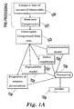
- Fig. 1A is a flow chart exemplifying a process for generating DTMOs and MDTMOs according to the method of the invention.
- first step 100 of the pre-processing stage directional fans of vectors of exposable heights (404 in Fig. 4) are extracted from the DTED.
- the main purpose of this step is to determine and collect terrain information that corresponds only to those sets of points which are of interest according to some predefined conditions. In this way, only the DTED information pertaining to the mission is gathered, and all the other DTED information, which is irrelevant to the specific mission plan (e.g., azimuth of approach), is discarded.
- This step results in a compact and reduced data set, which is convenient for data processing according to the method of the invention.
- step 101 the reduced data set that was obtained is compressed by eliminating redundant data points and by changing the data representation of the remaining data points into a compact and minimal representation, by applying a data transformation.
- the compressed data sets that are obtained in step 101 are then interrogated (by queries), in step 103, according to different aspects of the mission plan.
- the queries performed in step 103 are utilized to generate various types of DTMOs.
- Some of the DTMOs which are of particular importance in the present invention are the communication DTMO (step 106), the exposability DTMO (step 105), and safety conditions (step 107).
- the mission force/vehicle data e.g., velocities, heights, performance capabilities, etc.
- all the above mentioned DTMOs are processed in step 108 to obtain the MDTMO in step 109, which can provide all the pertinent information required for mission execution.
- the various DTMOs are generated utilizing two fundamental data sets, one data set comprising vectors of exposable heights (404) which are exposable by the terrain points (hereinafter source points), and the other data set comprising directional fans (220 in Fig. 5), consisting of the abovementioned vectors of exposable heights (404).
- the directional fans 220 are the initial data set, constructed from DTED points, which are utilized for the processing of DTED points according to the method of the invention.
- Each directional fan 220 is a collection of DTED information pertaining to a particular source point 200 (fan vertex).
- each directional fan holds the terrain information, pertaining to the source point 200, and which is within a predefined radius R max and a fan opening angle ⁇ (403).
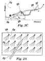
- the directional fans are constructed from DTED to include terrain information in correspondence with approach azimuth 223, as shown in Fig. 2A.
- each directional fan 220 collects the terrain line of sight information that is relevant to the mission specific conditions within a given terrain zone. This treatment substantially reduces the amount of data and processing required for producing various terrain models according to the method of the invention.
- vectors (also termed herein as vectors of exposable heights 404) constitute a fundamental unit of information, which includes heights and distances indicating the minimal altitude required to be in a line of sight (i.e., eye contact) with an examined source point 200 in the DTED.
- the vectors 404 (Fig. 4) are computed from a two-dimensional terrain profile 210, taken from the directional fans of DTED points 220, as shown in Figs. 2A, 2B, and 2C. Each point in a vector 404 is represented by its horizontal distance L from the source point 200 and its elevation angle ⁇ (Fig. 2C).
- the vector of exposable heights 404 are constructed from the line of sight points 203, which are the DTED points within said profile which has direct line of sight 215 to the source point 200.
- the selected terrain can be examined to reveal the minimal height required to maintain communication with a given ground point (e.g., control station), and the minimal height in which a given source point (e.g., Targets) may be exposed.
- a given ground point e.g., control station
- a given source point e.g., Targets
- step 100 in Fig. 1 the elevation angle ⁇ between each point in the terrain profile 210 and the source point 200 is computed (hereinafter angle of sight), and only points having an angle of sight that is greater than the angle of sight of the previous point are preserved.
- angle of sight the elevation angle between each point in the terrain profile 210 and the source point 200 is computed (hereinafter angle of sight), and only points having an angle of sight that is greater than the angle of sight of the previous point are preserved.
- Hidden points 202 are discarded, since the peak points 203 hide them, and they do not posses a direct line of sight with the source point 200.
- a line 207 of exposable heights is obtained, which contains only those terrain points, within the two-dimensional terrain profile 210, which are exposable by the source point 200.
- each directional fan 220 maintains only the information which is relevant according to the mission specifics (azimuth 223, R max , ⁇ , etc.). While this is a preferred method to discard redundant information according to the invention, it should be noted that the information included by the directional fans 220 may be compressed utilizing other methods suitable for the data processing that will be discussed hereinafter.
- the operations performed during the data processing steps also involve careful examination of additional aspects which are not discussed here for the sake of brevity. For instance, for the calculation of line of sight between terrain points the earth roundness (curvature) should also be considered, and for the communication DTMOs, the communication line curvature, as well as other pertinent aspects (e.g., the weather), which should also be considered.
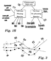
- This step (101 in Fig. 1A) is carried out in order to reduce the size of the data set of exposable heights in each line of exposable heights 207.
- the compression step 101 determines a minimal number of points in a line of exposable heights 207, which is required to obtain a line which deviates from the prior uncompressed line of exposable heights 207 within the tolerable deviation (209) allowed for the purpose of compression (e.g. less than 50 meters above/below the line of exposable heights 207). For example, DTED points 201 (Fig. 2B) are discarded since they fall within the tolerable deviation 209.
- This reduction in the number of data set points also substantially reduces the time durations required for each query to examine various aspects of the selected terrain, due to the reduction in the amount of information in each directional fan 220.
- the compression step is performed on the lines of exposable heights 207 of each and every directional fan 220, to yield a compressed set of directional fans.
- the compression starts by defining the maximal deviation (D, shown in Fig. 3) allowed from each point in the line of exposable heights 207.
- a "sleeve" of tolerable deviation is defined between the two lines, 207 and 300.
- the compressed data set is obtained from the set of the longest straight lines 310a-c that can be drawn within the sleeve of tolerable deviation.
- One way to carry out the compression process may be by performing the following steps:
- the data processing carried out according to the method of the invention is also unique due to the approach utilized to solve the exposability problem.
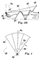
- an altitude should be determined, at which each target can be exposed.
- the visibility of air vehicles is confined to the limitations angle, and therefore the targets can be exposed only within this range of angles ⁇ .
- each of the targets can expose the air vehicle within the same range of angles, but with a 180° angle shift (since the exposability problem is symmetric). Therefore, the exposability problem can be inverted and solved according to the observablity of terrain points (in the view of the targets), and the air vehicle altitude in which the targets are visible to the mission force can be resolved in this way.
- the terrain is analyzed from a terrestrial point of view (i.e., targets' sight), but within the air vehicle limitations angle.
- the directional fans 220 consist of a set of vectors of exposable heights 404.
- the vertex of each directional fan is the source point 200, and the fan azimuth 401 is preferably the azimuth of the bisector of the fan opening angle, which is preferably opposite in direction to the approach azimuth 223 of the mission force (i.e., 180° angle shift), opening angle ⁇ (403), maximal range R max , and angular resolution 402 of ⁇ degrees between each vector of exposable heights 404.
- the maximal range R max is determined according to the destination terrain, the targets, and mission vehicle/force characteristics (e.g. visibility conditions).
- the opening angle used to construct the directional fans is determined according to the vehicle limitations angle.
- each directional fan 220 includes fundamental data sets according to the method of the invention.
- each directional fan 220 comprises: the maximal range R max ; directional fan opening angle ⁇ (403); fan azimuth 401; maximal compression deviation D ; height of source point 200 (measured relative to sea level); spatial location of the source point 200 in two-dimensional coordinates plain; vectors of exposable heights 404; and the direction of each vector of exposable heights.
- the digital terrain model obtained after performing the pre-processing steps (100 and 101) results in a Data Base (DB) of directional fans 220 consisting of a compressed vector of heights 404, which includes all the pertinent information required for the planning of the specific mission.
- the data processing for the mission planning proceeds by introducing queries concerning different mission aspects as shown in step 103 of Fig. 1A.
- This is an intermediate step in which a unique DTMO is constructed for each mission aspect.
- the exposability DTMO, communication DTMO (which usually includes a single directional fan), are constructed and then used in a later processing stage 108 in which the MDTMO is constructed.
- each DTMO contains information relevant to a specific mission aspect. Therefore, each query performed requires a lookup process limited only to fetching the desired information, which does not involve any complex computation.
- each DTMO includes numerous directional fans 220 covering the mission area, where each directional fan is directed in the opposite direction of the mission force/vehicle approach direction, and has an opening angle set according to the vehicle limitations angle.
- FIG. 5 An exemplary query process is sketched in Fig. 5.
- the relevant terrain model of compressed directional fans 500 is interrogated by a query.
- Each directional fan 220 is looked up and the relevant data 520 is retrieved, obtaining the respective DTMO shown in 501.
- the query result can be processed and displayed in the form of continuous contour lines in 502, each of which represents points having the same properties e.g., points which determine minimal altitude required for satisfying certain exposability conditions or which determine mission area coverage.
- a query will typically interrogate the DTMO DB of compressed directional fans for data concerning the altitude and/or distance required to satisfy predetermined conditions.
- the queries are performed in various stages of uncertainty. More particularly, these stages may be categorized into the following levels of uncertainty:
- step 111 in Fig. 1B the exact approach path is usually not known, and therefore the mission force/vehicle state during the mission execution (azimuths, altitudes, etc.) is not known.
- the terrain analysis is performed utilizing a rough approximation of the Mission force/vehicle state, and/or ranges of possible values of the same, and of course within the limitations angle.
- step 111 in Fig. 1B The compressed directional fans data sets (terrain information) 120 are interrogated utilizing said queries which yields DTMOs (DTMO1-DTMO4) which utilize the worst case results.
- This optimal track is determined according to various aspects. For instance, it may be influenced by the total mission distance and time frames, possible threats, and/or mission force/vehicle performance.
- This information is then used to further interrogate the compressed data set 120 with more specific queries.
- the queries may be used to obtain exposability information over said desired track without indicating a specific mission force/vehicle state.
- Such interrogation can be used by declaring a desired range from the destination over sections of the track in which the mission force/vehicle is exposed to destination sites.
- the queries may be used defining a desired duration of time in which the mission force/vehicle is exposed to the destination site.
- queries are typically performed during the mission execution, and thus involve more accurate information concerning the mission force/vehicle state. More particularly, in many cases this type of queries are performed for a given location and orientation in space of the mission force/vehicle. As exemplified in step 121 of Fig. 1B, the results that are obtained will usually include DTMOs of exact exposable areas, and/or areas in which communication can be established with another point(s) in space. Therefore, the compressed data sets 120 is analyzed by queries utilizing well defined mission force/vehicle state information, according to the actual location and state of the mission force/vehicle. Correspondingly, the DTMOs information obtained in this case is more accurate.
- on-line queries 121 are used for mission re-planning, which may be required for instance during the mission execution in situations in which an alternative mission plan is needed to successfully finalize the mission. Such scenarios are mostly probable due to new information gathered during the mission execution, or due to unexpected developments (e.g., weather conditions). However, such re-planning may also be carried out utilizing the of line queries, which were previously discussed, according to the level of uncertainty and the re-planning needs.
- the direction of approach of the mission vehicle can be defined according to one of the following:
- the communication model is usually constructed from a single directional fan the base of which is located at the mission control center, and its vectors of exposable heights 404 consist of points which are in line of sight with the control center. 701. This terrain model is treated in a similar fashion to extract DTMOs that indicates the minimal altitude in which communication can be established with the mission control center.
- the directional fan azimuth 702 is computed according to the path between the mission control center 701 and the destination 600, as shown in Fig. 7. It should be noted that the destination 600 may be a single point, as well as a collection of points defining a destined area for the mission assignment.
- the exposability DTMO includes a set of directional fans, each of which corresponds to a terrain point in the DTED of the mission area. These directional fans include all the information required to respond to exposability queries, for a given approach azimuth in the mission area.
- the exposability DTMO is created by performing the following steps:
- the method of the invention may be carried out in different ways.
- a DB of 360° fans is constructed, and only the relevant vectors on each fan are used for a given azimuth of approach.
- the size of the directional fans DB is further reduced by reducing the number of points required for different terrain cells according to the curvature and complexity of the different terrain cells.
- terrain areas which are relatively flat can be modeled by the use of a small set of DTED points, which results in a significant reduction in the size of the DTMO (i.e., less data is required).
- the size of the DTMO is even further reduced by utilizing a dynamic determination of the opening angle and angular resolution for each directional fan. In this way, for example, in areas which are relatively flat the angular resolution required may be reduced to further reduce the data of the directional fan.
- the method of the invention provides an efficient DTMO data base that enables query interrogation via a lookup process. Since the information is organized in the form of vectors of exposable height in the directional fans, for each query only the pertinent vectors are extracted from each fan in a lookup process.
- the data in the DTMO is preferably organized in a polar format (i.e., utilizing polar coordinates), which further simplifies the query lookup process.
- a line of sight is obtained by an interpolation of the vector data, and the results are transformed into a Cartesian coordinate system, as relevant to the assignment.
Landscapes
- Engineering & Computer Science (AREA)
- Radar, Positioning & Navigation (AREA)
- Remote Sensing (AREA)
- Automation & Control Theory (AREA)
- Physics & Mathematics (AREA)
- General Physics & Mathematics (AREA)
- Navigation (AREA)
- Structures Of Non-Positive Displacement Pumps (AREA)
- Geophysics And Detection Of Objects (AREA)
- Recording Measured Values (AREA)
- Position Fixing By Use Of Radio Waves (AREA)
Claims (40)
- Procédé pour traiter et analyser des données numériques de terrain, comportant les étapes consistant à :a) fournir des Données Numériques d'Altitude (DTED),b) définir un azimut d'approche (223) et un angle de limitations de visibilité,c) définir des éventails directionnels (404) en déterminant un angle d'ouverture d'éventail (403), un azimut d'éventail (401), et une portée maximale (Rmax) pour une analyse de terrain,d) construire au moins un ensemble de données d'éventail directionnel, à partir d'au moins une source ponctuelle (200) dans les DTED, qui contient les informations de ligne de visée entre ladite source ponctuelle et lesdits points DTED situés dans ledit éventail directionnel, ete) interroger lesdits ensembles de données à l'aide d'une ou plusieurs interrogations pour obtenir des informations de terrain pour des conditions d'approche données.
- Procédé selon la revendication 1, dans lequel l'azimut d'éventail directionnel est déterminé conformément à l'azimut d'approche.
- Procédé selon la revendication 1, dans lequel l'angle d'ouverture d'éventail est déterminé conformément à l'angle de limitations de visibilité.
- Procédé selon la revendication 3, comportant de plus la définition d'une résolution angulaire d'éventail.
- Procédé selon la revendication 4, dans lequel la résolution angulaire d'éventail est déterminée conformément à l'angle d'ouverture d'éventail et à la portée maximale d'éventail.
- Procédé selon la revendication 1, dans lequel l'azimut d'éventail est établi à l'azimut opposé de l'azimut d'approche.
- Procédé selon la revendication 4, dans lequel les éventails directionnels sont construits à partir d'un ou plusieurs ensembles de données de hauteurs exposables, en réalisant les étapes suivantes consistant à :a) diviser de manière régulière la surface d'éventail en sections angulaires conformément à la résolution angulaire d'éventail,b) construire un ensemble de données de hauteurs exposables pour chaque section angulaire, en calculant pour chaque point dans la section angulaire la distance et l'angle d'élévation dudit point par rapport à la source ponctuelle d'éventail,c) déterminer pour chaque point dans un ensemble de données de hauteurs exposables si ledit point se trouve dans la ligne de visée avec la source ponctuelle d'éventail, etd) rejeter les informations associées aux points dans un ensemble de données de hauteurs exposables qui ne se trouvent pas dans la ligne de visée avec la source ponctuelle d'éventail,de manière à obtenir dans chaque éventail directionnel un ensemble de données de hauteurs exposables incluant les informations des points DTED, dans lesdites sections angulaires, qui se trouvent dans la lignée de visée avec la source ponctuelle d'éventail, et qui sont des azimuts correspondants.
- Procédé selon la revendication 1 ou 7, comportant de plus la compression des données des éventails directionnels en appliquant une transformation de données.
- Procédé selon les revendications 7 et 8, dans lequel les données d'un éventail directionnel sont comprimées en effectuant les étapes suivantes consistant à :a) définir un écart tolérable pour une compression,b) pour chaque ensemble de données de hauteurs exposables, définir une ligne de hauteurs exposables qui est tracée entre les points, de la section angulaire respective, qui se trouvent dans la ligne de visée avec la source ponctuelle d'éventail, en commençant par le point le plus proche et en terminant par le point le plus éloigné, dans leur suite respective par rapport à ladite source ponctuelle,c) pour chaque de ligne de hauteurs exposables, définir une chemise d'écart tolérable en ajoutant l'écart tolérable D aux points de ladite ligne de hauteurs exposables,d) pour chaque section angulaire, comprimer les données de la ligne de hauteurs exposables en effectuant les étapes suivantes consistant à :d.1) tracer la ligne rectiligne la plus longue possible dans la chemise d'écart tolérable en commençant au niveau du bord de ladite chemise,d.2) définir un point final sur ladite ligne la plus longue dans ladite chemise à la section la plus éloignée où ladite ligne la plus longue croise une des frontières de ladite chemise,d.3) tracer la ligne la plus longue suivante en commençant par ledit point final de la ligne précédente, etd.4) répéter les étapes d.1) à d.3) jusqu'à ce que l'extrémité de ladite chemise soit atteinte.
- Procédé selon la revendication 9, dans lequel une compression de données de la ligne de hauteurs exposables est effectuée en commençant par les points les plus éloignés dans la section angulaire et en se déplaçant vers la source ponctuelle.
- Procédé selon la revendication 9, dans lequel les données de chaque éventail directionnel sont organisées en utilisant un système de coordonnée polaire.
- Procédé selon la revendication 11, dans lequel les données obtenues à partir d'un éventail directionnel sont transformées d'une représentation polaire en une représentation cartésienne.
- Procédé selon la revendication 9, dans lequel les données pertinentes sont obtenues à partir des éventails directionnels via un processus de consultation.
- Procédé selon la revendication 9, dans lequel les données obtenues par interrogation comportent de plus une interpolation des données dans une section angulaire.
- Procédé selon les revendications 1 à 14, dans lequel l'ensemble de données d'éventail directionnel comporte la portée maximale, l'angle d'ouverture d'éventail, la direction d'éventail, l'écart de compression maximal, la hauteur de la source ponctuelle, l'emplacement spatial de la source ponctuelle, et les vecteurs de hauteurs exposables et leur direction.
- Procédé selon la revendication 1 ou 7, dans lequel l'angle d'ouverture d'éventail est établi à 360°.
- Procédé selon la revendication 16, dans lequel l'interrogation de l'ensemble de données d'éventail est effectuée en extrayant à partir de chaque ensemble de données d'éventail les lignes de hauteurs exposables qui sont des azimuts qui se trouvent dans un angle d'ouverture dirigé dans la direction opposée à celle de l'azimut d'approche.
- Procédé selon l'une quelconque des revendications 1 à 17, dans lequel l'interrogation de l'ensemble de données d'éventail est effectuée à l'aide d'une ou plusieurs interrogations pour détecter les altitudes minimales, la communication et/ou ligne de visée pouvant être établies avec des points DTED.
- Procédé selon la revendication 18, dans lequel une ou plusieurs des interrogations suivantes sont utilisées pour déterminer :a) l'altitude minimale requise pour établir une visée pour une distance et un azimut d'approche donnés,b) l'altitude minimale requise pour établir une communication avec un point donné, etc) la distance minimale requise pour établir une ligne de visée avec des points de terrain pour une altitude et un azimut d'approche donnés.
- Procédé selon la revendication 18, dans lequel l'interrogation de l'ensemble de données d'éventail est effectuée à l'aide d'une ou plusieurs interrogations de la liste suivante :- interrogations d'azimut d'approche inconnu, en utilisant un azimut d'approche général ou une distance d'azimuts d'approche possibles, et utiliser les résultats du pire cas,- interrogations avec un azimut connu d'approche ou ayant un trajet d'approche général, mais l'état exact étant partiellement connu ou inconnu, et- interrogations d'un emplacement spécifique pour analyser rapidement un emplacement exact.
- Système pour traiter et analyser des données numériques de terrain, comportant :a) des Données Numériques d'Altitude (DTED),b) des moyens pour définir un azimut d'approche (223) et un angle de limitations de visibilité,c) des moyens pour définir des éventails directionnels (404) en déterminant un angle d'ouverture d'éventail (403), un azimut d'éventail (401), et une portée maximale (Rmax) pour une analyse de terrain,d) des moyens pour construire au moins un ensemble de données d'éventail directionnels, à partir d'au moins une source ponctuelle (200) dans les DTED, qui contient les informations de ligne de visée entre ladite source ponctuelle et des points DTED situés dans l'éventail directionnel, ete) des moyens pour interroger lesdits ensembles de données à l'aide d'une ou plusieurs interrogations pour obtenir des informations de terrain pour des conditions d'approche données.
- Système selon la revendication 21, dans lequel l'azimut d'éventail est déterminé conformément à l'azimut d'approche.
- Système selon la revendication 21, dans lequel l'angle d'ouverture d'éventail est déterminé conformément à l'angle de limitations de visibilité.
- Système selon la revendication 23, comportant de plus des moyens pour définir une résolution angulaire d'éventail.
- Système selon la revendication 24, dans lequel la résolution angulaire d'éventail est déterminée conformément à l'angle d'ouverture d'éventail et à la portée maximale d'éventail.
- Système selon la revendication 21, dans lequel l'azimut d'éventail est établi à l'azimut opposé de l'azimut d'approche.
- Système selon la revendication 24, dans lequel les éventails directionnels sont construits à partir d'un ou plusieurs ensembles de données de hauteurs exposables, en réalisant les étapes suivantes consistant à :a) diviser de manière régulière la surface d'éventail en sections angulaires conformément à la résolution angulaire d'éventail,b) construire un ensemble de données de hauteurs exposables pour chaque section angulaire, en calculant pour chaque point dans la section angulaire la distance et l'angle d'élévation dudit point par rapport à la source ponctuelle d'éventail,c) déterminer pour chaque point dans un ensemble de données de hauteurs exposables si ledit point se trouve dans la ligne de visée avec la source ponctuelle d'éventail, etd) rejeter les informations associées aux points dans un ensemble de données de hauteurs exposables qui ne se trouvent pas dans la ligne de visée avec la source ponctuelle d'éventail,de manière à obtenir dans chaque éventail directionnel un ensemble de données de hauteurs exposables incluant les informations des points DTED, dans lesdites sections angulaires, qui se trouvent dans la lignée de visée avec la source ponctuelle d'éventail, et qui sont des azimuts correspondants.
- Système selon la revendication 21 ou 27, comportant de plus des moyens pour comprimer les données des éventails directionnels en appliquant une transformation de données.
- Système selon la revendication 28, dans lequel les données d'un éventail directionnel sont comprimées en effectuant les étapes suivantes consistant à :a) définir un écart tolérable pour une compression,b) pour chaque ensemble de données de hauteurs exposables, définir une ligne de hauteurs exposables qui est tracée entre les points, de la section angulaire respective, qui se trouvent dans la ligne de visée avec la source ponctuelle d'éventail, en commençant par le point le plus proche et en terminant par le point le plus éloigné, dans leur suite respective par rapport à ladite source ponctuelle,c) pour chaque de ligne de hauteurs exposables, définir une chemise d'écart tolérable en ajoutant l'écart tolérable D aux points de ladite ligne de hauteurs exposables,d) pour chaque section angulaire, comprimer les données de la ligne de hauteurs exposables en effectuant les étapes suivantes consistant à :d.1) tracer la ligne rectiligne la plus longue possible dans la chemise d'écart tolérable en commençant au niveau du bord de ladite chemise,d.2) définir un point final sur ladite ligne la plus longue dans ladite chemise à la section la plus éloignée où ladite ligne la plus longue croise une des frontières de ladite chemise,d.3) tracer la ligne la plus longue suivante en commençant par ledit point final de la ligne précédente, etd.4) répéter les étapes 2 à 4 jusqu'à ce que l'extrémité de ladite chemise soit atteinte.
- Système selon la revendication 29, dans lequel une compression de données de la ligne de hauteurs exposables est effectuée en commençant par les points les plus éloignés dans la section angulaire et en se déplaçant vers la source ponctuelle.
- Procédé selon la revendication 29, dans lequel les données de chaque éventail directionnel sont organisées en utilisant un système de coordonnée polaire.
- Système selon la revendication 31, dans lequel les données obtenues à partir d'un éventail directionnel sont transformées d'une représentation polaire en une représentation cartésienne.
- Système selon la revendication 31, dans lequel les données pertinentes sont obtenues à partir du ou des éventails directionnels via un processus de consultation.
- Système selon la revendication 31, dans lequel les données obtenues par interrogation comportent de plus une interpolation des données dans une section angulaire.
- Système selon les revendications 21 à 34, dans lequel l'ensemble de données d'éventail directionnel comporte la portée maximale, l'angle d'ouverture d'éventail, la direction d'éventail, l'écart de compression maximal, la hauteur de la source ponctuelle, l'emplacement spatial de la source ponctuelle, et les vecteurs de hauteurs exposables et leur direction.
- Système selon la revendication 21 ou 27, dans lequel l'angle d'ouverture d'éventail est établi à 360°.
- Système selon la revendication 21, dans lequel l'interrogation de l'ensemble de données d'éventail est effectuée en extrayant à partir de chaque ensemble de données d'éventail les lignes de hauteurs exposables qui sont des azimuts qui se trouvent dans un angle d'ouverture dirigé dans la direction opposée à celle de l'azimut d'approche.
- Système selon l'une quelconque des revendications 21 à 37, dans lequel l'interrogation de l'ensemble de données d'éventail est effectuée à l'aide d'une ou plusieurs interrogations pour détecter les altitudes minimales, la communication et/ou la ligne de visée pouvant être établies avec des points DTED.
- Système selon la revendication 38, dans lequel une ou plusieurs des interrogations suivantes sont utilisées pour déterminer :a) l'altitude minimale requise pour établir une visée pour une distance et un azimut d'approche donnés,b) l'altitude minimale requise pour établir une communication avec un point donné, etc) la distance minimale requise pour établir une ligne de visée avec des points de terrain pour une altitude et un azimut d'approche donnés.
- Système selon la revendication 21, dans lequel l'interrogation de l'ensemble de données d'éventail est effectuée à l'aide d'une ou plusieurs interrogations de la liste suivante :- interrogations d'azimut d'approche inconnu, en utilisant un azimut d'approche général ou une distance d'azimuts d'approche possibles, et utiliser les résultats du pire cas,- interrogations avec un azimut connu d'approche ou ayant un trajet d'approche général, mais l'état exact étant partiellement connu ou inconnu, et- interrogations d'un emplacement spécifique pour analyser rapidement un emplacement exact.
Applications Claiming Priority (3)
| Application Number | Priority Date | Filing Date | Title |
|---|---|---|---|
| IL153535A IL153535A (en) | 2002-12-19 | 2002-12-19 | Method and system for processing and analyzing digital data of the surface |
| IL15353502 | 2002-12-19 | ||
| PCT/IL2003/001092 WO2004057268A2 (fr) | 2002-12-19 | 2003-12-19 | Procede et systeme pour traiter et analyser les donnees numeriques de terrain |
Publications (2)
| Publication Number | Publication Date |
|---|---|
| EP1573269A2 EP1573269A2 (fr) | 2005-09-14 |
| EP1573269B1 true EP1573269B1 (fr) | 2006-09-13 |
Family
ID=32652218
Family Applications (1)
| Application Number | Title | Priority Date | Filing Date |
|---|---|---|---|
| EP03768085A Expired - Lifetime EP1573269B1 (fr) | 2002-12-19 | 2003-12-19 | Procede et systeme pour traiter et analyser les donnees numeriques de terrain |
Country Status (8)
| Country | Link |
|---|---|
| US (1) | US7403856B2 (fr) |
| EP (1) | EP1573269B1 (fr) |
| AT (1) | ATE339672T1 (fr) |
| AU (1) | AU2003292503A1 (fr) |
| CA (1) | CA2508320C (fr) |
| DE (1) | DE60308413T2 (fr) |
| IL (1) | IL153535A (fr) |
| WO (1) | WO2004057268A2 (fr) |
Families Citing this family (45)
| Publication number | Priority date | Publication date | Assignee | Title |
|---|---|---|---|---|
| FR2867851B1 (fr) * | 2004-03-19 | 2006-05-26 | Thales Sa | Procede de reperage, sur une carte, de points difficiles d'acces |
| US9104695B1 (en) | 2009-07-27 | 2015-08-11 | Palantir Technologies, Inc. | Geotagging structured data |
| FR2954540B1 (fr) | 2009-12-23 | 2018-11-16 | Thales | Procede de classification d'objets dans un systeme de veille par imagerie. |
| US20130035861A1 (en) * | 2011-08-03 | 2013-02-07 | Harris Corporation | Mission specific terrain analysis |
| US9501507B1 (en) | 2012-12-27 | 2016-11-22 | Palantir Technologies Inc. | Geo-temporal indexing and searching |
| US9123086B1 (en) | 2013-01-31 | 2015-09-01 | Palantir Technologies, Inc. | Automatically generating event objects from images |
| US10037314B2 (en) | 2013-03-14 | 2018-07-31 | Palantir Technologies, Inc. | Mobile reports |
| US8799799B1 (en) | 2013-05-07 | 2014-08-05 | Palantir Technologies Inc. | Interactive geospatial map |
| IL226752A (en) * | 2013-06-04 | 2017-02-28 | Padowicz Ronen | Independent navigation system and method |
| US9041708B2 (en) * | 2013-07-23 | 2015-05-26 | Palantir Technologies, Inc. | Multiple viewshed analysis |
| US8938686B1 (en) | 2013-10-03 | 2015-01-20 | Palantir Technologies Inc. | Systems and methods for analyzing performance of an entity |
| US8924872B1 (en) | 2013-10-18 | 2014-12-30 | Palantir Technologies Inc. | Overview user interface of emergency call data of a law enforcement agency |
| US9021384B1 (en) | 2013-11-04 | 2015-04-28 | Palantir Technologies Inc. | Interactive vehicle information map |
| US8868537B1 (en) | 2013-11-11 | 2014-10-21 | Palantir Technologies, Inc. | Simple web search |
| US9727376B1 (en) | 2014-03-04 | 2017-08-08 | Palantir Technologies, Inc. | Mobile tasks |
| US9805058B2 (en) * | 2014-06-01 | 2017-10-31 | Microsoft Technology Licensing, Llc | Visibility of a point of interest based on environmental conditions |
| US9129219B1 (en) | 2014-06-30 | 2015-09-08 | Palantir Technologies, Inc. | Crime risk forecasting |
| US10372879B2 (en) | 2014-12-31 | 2019-08-06 | Palantir Technologies Inc. | Medical claims lead summary report generation |
| US9891808B2 (en) | 2015-03-16 | 2018-02-13 | Palantir Technologies Inc. | Interactive user interfaces for location-based data analysis |
| US9460175B1 (en) | 2015-06-03 | 2016-10-04 | Palantir Technologies Inc. | Server implemented geographic information system with graphical interface |
| US9600146B2 (en) | 2015-08-17 | 2017-03-21 | Palantir Technologies Inc. | Interactive geospatial map |
| US10706434B1 (en) | 2015-09-01 | 2020-07-07 | Palantir Technologies Inc. | Methods and systems for determining location information |
| US9639580B1 (en) | 2015-09-04 | 2017-05-02 | Palantir Technologies, Inc. | Computer-implemented systems and methods for data management and visualization |
| US10109094B2 (en) | 2015-12-21 | 2018-10-23 | Palantir Technologies Inc. | Interface to index and display geospatial data |
| US11353326B2 (en) * | 2016-03-06 | 2022-06-07 | Arizona Board Of Regents On Behalf Of The University Of Arizona | Traverse and trajectory optimization and multi-purpose tracking |
| US10068199B1 (en) | 2016-05-13 | 2018-09-04 | Palantir Technologies Inc. | System to catalogue tracking data |
| US9686357B1 (en) | 2016-08-02 | 2017-06-20 | Palantir Technologies Inc. | Mapping content delivery |
| US10437840B1 (en) | 2016-08-19 | 2019-10-08 | Palantir Technologies Inc. | Focused probabilistic entity resolution from multiple data sources |
| US10515433B1 (en) | 2016-12-13 | 2019-12-24 | Palantir Technologies Inc. | Zoom-adaptive data granularity to achieve a flexible high-performance interface for a geospatial mapping system |
| US10270727B2 (en) | 2016-12-20 | 2019-04-23 | Palantir Technologies, Inc. | Short message communication within a mobile graphical map |
| US10460602B1 (en) | 2016-12-28 | 2019-10-29 | Palantir Technologies Inc. | Interactive vehicle information mapping system |
| US10579239B1 (en) | 2017-03-23 | 2020-03-03 | Palantir Technologies Inc. | Systems and methods for production and display of dynamically linked slide presentations |
| US10895946B2 (en) | 2017-05-30 | 2021-01-19 | Palantir Technologies Inc. | Systems and methods for using tiled data |
| US11334216B2 (en) | 2017-05-30 | 2022-05-17 | Palantir Technologies Inc. | Systems and methods for visually presenting geospatial information |
| US10403011B1 (en) | 2017-07-18 | 2019-09-03 | Palantir Technologies Inc. | Passing system with an interactive user interface |
| US10371537B1 (en) | 2017-11-29 | 2019-08-06 | Palantir Technologies Inc. | Systems and methods for flexible route planning |
| US11599706B1 (en) | 2017-12-06 | 2023-03-07 | Palantir Technologies Inc. | Systems and methods for providing a view of geospatial information |
| US10698756B1 (en) | 2017-12-15 | 2020-06-30 | Palantir Technologies Inc. | Linking related events for various devices and services in computer log files on a centralized server |
| US10896234B2 (en) | 2018-03-29 | 2021-01-19 | Palantir Technologies Inc. | Interactive geographical map |
| US10830599B2 (en) | 2018-04-03 | 2020-11-10 | Palantir Technologies Inc. | Systems and methods for alternative projections of geographical information |
| US11585672B1 (en) | 2018-04-11 | 2023-02-21 | Palantir Technologies Inc. | Three-dimensional representations of routes |
| US10429197B1 (en) | 2018-05-29 | 2019-10-01 | Palantir Technologies Inc. | Terrain analysis for automatic route determination |
| US10467435B1 (en) | 2018-10-24 | 2019-11-05 | Palantir Technologies Inc. | Approaches for managing restrictions for middleware applications |
| US11025672B2 (en) | 2018-10-25 | 2021-06-01 | Palantir Technologies Inc. | Approaches for securing middleware data access |
| CN120296105B (zh) * | 2025-06-13 | 2025-09-02 | 武汉市金叶云景观科技有限公司 | 一种工程测绘系统 |
Family Cites Families (5)
| Publication number | Priority date | Publication date | Assignee | Title |
|---|---|---|---|---|
| DE3604401A1 (de) * | 1986-02-12 | 1987-08-20 | Messerschmitt Boelkow Blohm | Tiefflugverfahren zur automatischen kursbestimmung |
| US5086396A (en) * | 1989-02-02 | 1992-02-04 | Honeywell Inc. | Apparatus and method for an aircraft navigation system having improved mission management and survivability capabilities |
| US5504686A (en) * | 1993-11-30 | 1996-04-02 | Honeywell Inc. | Mission planning costing surface |
| IL112186A (en) * | 1994-01-18 | 1998-09-24 | Honeywell Inc | A device for calculating inter-point vision |
| US5838262A (en) * | 1996-12-19 | 1998-11-17 | Sikorsky Aircraft Corporation | Aircraft virtual image display system and method for providing a real-time perspective threat coverage display |
-
2002
- 2002-12-19 IL IL153535A patent/IL153535A/en active IP Right Grant
-
2003
- 2003-12-19 WO PCT/IL2003/001092 patent/WO2004057268A2/fr not_active Ceased
- 2003-12-19 EP EP03768085A patent/EP1573269B1/fr not_active Expired - Lifetime
- 2003-12-19 CA CA2508320A patent/CA2508320C/fr not_active Expired - Fee Related
- 2003-12-19 DE DE60308413T patent/DE60308413T2/de not_active Expired - Lifetime
- 2003-12-19 AT AT03768085T patent/ATE339672T1/de not_active IP Right Cessation
- 2003-12-19 US US10/536,937 patent/US7403856B2/en not_active Expired - Lifetime
- 2003-12-19 AU AU2003292503A patent/AU2003292503A1/en not_active Abandoned
Also Published As
| Publication number | Publication date |
|---|---|
| CA2508320A1 (fr) | 2004-07-08 |
| EP1573269A2 (fr) | 2005-09-14 |
| AU2003292503A1 (en) | 2004-07-14 |
| IL153535A (en) | 2007-12-03 |
| WO2004057268A2 (fr) | 2004-07-08 |
| CA2508320C (fr) | 2010-03-30 |
| AU2003292503A8 (en) | 2004-07-14 |
| IL153535A0 (en) | 2004-02-19 |
| US7403856B2 (en) | 2008-07-22 |
| US20060184327A1 (en) | 2006-08-17 |
| WO2004057268A3 (fr) | 2004-09-16 |
| ATE339672T1 (de) | 2006-10-15 |
| DE60308413T2 (de) | 2007-09-13 |
| DE60308413D1 (de) | 2006-10-26 |
Similar Documents
| Publication | Publication Date | Title |
|---|---|---|
| EP1573269B1 (fr) | Procede et systeme pour traiter et analyser les donnees numeriques de terrain | |
| US4891762A (en) | Method and apparatus for tracking, mapping and recognition of spatial patterns | |
| US6317690B1 (en) | Path planning, terrain avoidance and situation awareness system for general aviation | |
| EP1065470A1 (fr) | Système de planification de trajectoire, d'anticollision terrain et d'affichage de perspective pour l'aviation générale | |
| US20010055063A1 (en) | Position detection apparatus, position detection method and position detection program | |
| WO2021021862A1 (fr) | Système de cartographie et de localisation de véhicules autonomes | |
| CN112639502A (zh) | 机器人位姿估计 | |
| CN112904358B (zh) | 基于几何信息的激光定位方法 | |
| CN114140761A (zh) | 点云配准方法、装置、计算机设备和存储介质 | |
| CN111709988A (zh) | 一种物体的特征信息的确定方法、装置、电子设备及存储介质 | |
| US20210405197A1 (en) | GLOBAL LOCALIZATION APPARATUS AND METHOD IN DYNAMIC ENVIRONMENTS USING 3D LiDAR SCANNER | |
| CN113077473A (zh) | 三维激光点云路面分割方法、系统、计算机设备及介质 | |
| CN117170406A (zh) | 一种基于分层规划的无人机快速自主搜寻方法 | |
| US12229987B2 (en) | Simultaneous localization and mapping (SLAM) method | |
| Yousuf et al. | Improving the Position Accuracy and Computational Efficiency of UAV Terrain Aided Navigation Using a Two-Stage Hybrid Fuzzy Particle Filtering Method. | |
| US7295203B2 (en) | Determining regions that are occluded from an observation point | |
| Tse et al. | 3D city modelling from LIDAR data | |
| CN116704024B (zh) | 一种联合多类约束的车载激光点云位姿图优化方法及系统 | |
| CN118037790A (zh) | 一种点云处理方法、装置、计算机设备及存储介质 | |
| CN116540206A (zh) | 一种足式机器人高程估计方法、装置及系统 | |
| Guo et al. | Occupancy grid based urban localization using weighted point cloud | |
| US8798957B2 (en) | Method for the computer-aided calculation of the movement of an object using sensor data | |
| US6199471B1 (en) | Method and system for determining the probable location of a contact | |
| CN118999526A (zh) | 一种基于地图动态更新的机器人路径规划方法及系统 | |
| EP0655714A1 (fr) | Transformation des données digitales de site pour révéler des zones de faible visibilité |
Legal Events
| Date | Code | Title | Description |
|---|---|---|---|
| PUAI | Public reference made under article 153(3) epc to a published international application that has entered the european phase |
Free format text: ORIGINAL CODE: 0009012 |
|
| 17P | Request for examination filed |
Effective date: 20050603 |
|
| AK | Designated contracting states |
Kind code of ref document: A2 Designated state(s): AT BE BG CH CY CZ DE DK EE ES FI FR GB GR HU IE IT LI LU MC NL PT RO SE SI SK TR |
|
| AX | Request for extension of the european patent |
Extension state: AL LT LV MK |
|
| GRAP | Despatch of communication of intention to grant a patent |
Free format text: ORIGINAL CODE: EPIDOSNIGR1 |
|
| DAX | Request for extension of the european patent (deleted) | ||
| GRAS | Grant fee paid |
Free format text: ORIGINAL CODE: EPIDOSNIGR3 |
|
| GRAA | (expected) grant |
Free format text: ORIGINAL CODE: 0009210 |
|
| AK | Designated contracting states |
Kind code of ref document: B1 Designated state(s): AT BE BG CH CY CZ DE DK EE ES FI FR GB GR HU IE IT LI LU MC NL PT RO SE SI SK TR |
|
| PG25 | Lapsed in a contracting state [announced via postgrant information from national office to epo] |
Ref country code: IT Free format text: LAPSE BECAUSE OF FAILURE TO SUBMIT A TRANSLATION OF THE DESCRIPTION OR TO PAY THE FEE WITHIN THE PRESCRIBED TIME-LIMIT;WARNING: LAPSES OF ITALIAN PATENTS WITH EFFECTIVE DATE BEFORE 2007 MAY HAVE OCCURRED AT ANY TIME BEFORE 2007. THE CORRECT EFFECTIVE DATE MAY BE DIFFERENT FROM THE ONE RECORDED. Effective date: 20060913 Ref country code: CZ Free format text: LAPSE BECAUSE OF FAILURE TO SUBMIT A TRANSLATION OF THE DESCRIPTION OR TO PAY THE FEE WITHIN THE PRESCRIBED TIME-LIMIT Effective date: 20060913 Ref country code: NL Free format text: LAPSE BECAUSE OF FAILURE TO SUBMIT A TRANSLATION OF THE DESCRIPTION OR TO PAY THE FEE WITHIN THE PRESCRIBED TIME-LIMIT Effective date: 20060913 Ref country code: BE Free format text: LAPSE BECAUSE OF FAILURE TO SUBMIT A TRANSLATION OF THE DESCRIPTION OR TO PAY THE FEE WITHIN THE PRESCRIBED TIME-LIMIT Effective date: 20060913 Ref country code: AT Free format text: LAPSE BECAUSE OF FAILURE TO SUBMIT A TRANSLATION OF THE DESCRIPTION OR TO PAY THE FEE WITHIN THE PRESCRIBED TIME-LIMIT Effective date: 20060913 Ref country code: CH Free format text: LAPSE BECAUSE OF FAILURE TO SUBMIT A TRANSLATION OF THE DESCRIPTION OR TO PAY THE FEE WITHIN THE PRESCRIBED TIME-LIMIT Effective date: 20060913 Ref country code: RO Free format text: LAPSE BECAUSE OF FAILURE TO SUBMIT A TRANSLATION OF THE DESCRIPTION OR TO PAY THE FEE WITHIN THE PRESCRIBED TIME-LIMIT Effective date: 20060913 Ref country code: LI Free format text: LAPSE BECAUSE OF FAILURE TO SUBMIT A TRANSLATION OF THE DESCRIPTION OR TO PAY THE FEE WITHIN THE PRESCRIBED TIME-LIMIT Effective date: 20060913 Ref country code: SI Free format text: LAPSE BECAUSE OF FAILURE TO SUBMIT A TRANSLATION OF THE DESCRIPTION OR TO PAY THE FEE WITHIN THE PRESCRIBED TIME-LIMIT Effective date: 20060913 Ref country code: FI Free format text: LAPSE BECAUSE OF FAILURE TO SUBMIT A TRANSLATION OF THE DESCRIPTION OR TO PAY THE FEE WITHIN THE PRESCRIBED TIME-LIMIT Effective date: 20060913 Ref country code: SK Free format text: LAPSE BECAUSE OF FAILURE TO SUBMIT A TRANSLATION OF THE DESCRIPTION OR TO PAY THE FEE WITHIN THE PRESCRIBED TIME-LIMIT Effective date: 20060913 |
|
| REG | Reference to a national code |
Ref country code: GB Ref legal event code: FG4D |
|
| REG | Reference to a national code |
Ref country code: CH Ref legal event code: EP |
|
| REG | Reference to a national code |
Ref country code: IE Ref legal event code: FG4D |
|
| REF | Corresponds to: |
Ref document number: 60308413 Country of ref document: DE Date of ref document: 20061026 Kind code of ref document: P |
|
| PG25 | Lapsed in a contracting state [announced via postgrant information from national office to epo] |
Ref country code: SE Free format text: LAPSE BECAUSE OF FAILURE TO SUBMIT A TRANSLATION OF THE DESCRIPTION OR TO PAY THE FEE WITHIN THE PRESCRIBED TIME-LIMIT Effective date: 20061213 Ref country code: BG Free format text: LAPSE BECAUSE OF FAILURE TO SUBMIT A TRANSLATION OF THE DESCRIPTION OR TO PAY THE FEE WITHIN THE PRESCRIBED TIME-LIMIT Effective date: 20061213 Ref country code: DK Free format text: LAPSE BECAUSE OF FAILURE TO SUBMIT A TRANSLATION OF THE DESCRIPTION OR TO PAY THE FEE WITHIN THE PRESCRIBED TIME-LIMIT Effective date: 20061213 |
|
| PG25 | Lapsed in a contracting state [announced via postgrant information from national office to epo] |
Ref country code: IE Free format text: LAPSE BECAUSE OF NON-PAYMENT OF DUE FEES Effective date: 20061219 |
|
| PG25 | Lapsed in a contracting state [announced via postgrant information from national office to epo] |
Ref country code: ES Free format text: LAPSE BECAUSE OF FAILURE TO SUBMIT A TRANSLATION OF THE DESCRIPTION OR TO PAY THE FEE WITHIN THE PRESCRIBED TIME-LIMIT Effective date: 20061224 |
|
| PG25 | Lapsed in a contracting state [announced via postgrant information from national office to epo] |
Ref country code: MC Free format text: LAPSE BECAUSE OF NON-PAYMENT OF DUE FEES Effective date: 20061231 |
|
| PG25 | Lapsed in a contracting state [announced via postgrant information from national office to epo] |
Ref country code: PT Free format text: LAPSE BECAUSE OF FAILURE TO SUBMIT A TRANSLATION OF THE DESCRIPTION OR TO PAY THE FEE WITHIN THE PRESCRIBED TIME-LIMIT Effective date: 20070226 |
|
| NLV1 | Nl: lapsed or annulled due to failure to fulfill the requirements of art. 29p and 29m of the patents act | ||
| REG | Reference to a national code |
Ref country code: CH Ref legal event code: PL |
|
| ET | Fr: translation filed | ||
| PLBE | No opposition filed within time limit |
Free format text: ORIGINAL CODE: 0009261 |
|
| STAA | Information on the status of an ep patent application or granted ep patent |
Free format text: STATUS: NO OPPOSITION FILED WITHIN TIME LIMIT |
|
| 26N | No opposition filed |
Effective date: 20070614 |
|
| PG25 | Lapsed in a contracting state [announced via postgrant information from national office to epo] |
Ref country code: GR Free format text: LAPSE BECAUSE OF FAILURE TO SUBMIT A TRANSLATION OF THE DESCRIPTION OR TO PAY THE FEE WITHIN THE PRESCRIBED TIME-LIMIT Effective date: 20061214 |
|
| PG25 | Lapsed in a contracting state [announced via postgrant information from national office to epo] |
Ref country code: EE Free format text: LAPSE BECAUSE OF FAILURE TO SUBMIT A TRANSLATION OF THE DESCRIPTION OR TO PAY THE FEE WITHIN THE PRESCRIBED TIME-LIMIT Effective date: 20060913 |
|
| PG25 | Lapsed in a contracting state [announced via postgrant information from national office to epo] |
Ref country code: TR Free format text: LAPSE BECAUSE OF FAILURE TO SUBMIT A TRANSLATION OF THE DESCRIPTION OR TO PAY THE FEE WITHIN THE PRESCRIBED TIME-LIMIT Effective date: 20060913 Ref country code: LU Free format text: LAPSE BECAUSE OF NON-PAYMENT OF DUE FEES Effective date: 20061219 Ref country code: HU Free format text: LAPSE BECAUSE OF FAILURE TO SUBMIT A TRANSLATION OF THE DESCRIPTION OR TO PAY THE FEE WITHIN THE PRESCRIBED TIME-LIMIT Effective date: 20070314 |
|
| PG25 | Lapsed in a contracting state [announced via postgrant information from national office to epo] |
Ref country code: CY Free format text: LAPSE BECAUSE OF FAILURE TO SUBMIT A TRANSLATION OF THE DESCRIPTION OR TO PAY THE FEE WITHIN THE PRESCRIBED TIME-LIMIT Effective date: 20060913 |
|
| PGFP | Annual fee paid to national office [announced via postgrant information from national office to epo] |
Ref country code: FR Payment date: 20110107 Year of fee payment: 8 |
|
| PGFP | Annual fee paid to national office [announced via postgrant information from national office to epo] |
Ref country code: GB Payment date: 20101230 Year of fee payment: 8 |
|
| PGFP | Annual fee paid to national office [announced via postgrant information from national office to epo] |
Ref country code: DE Payment date: 20110225 Year of fee payment: 8 |
|
| GBPC | Gb: european patent ceased through non-payment of renewal fee |
Effective date: 20111219 |
|
| REG | Reference to a national code |
Ref country code: FR Ref legal event code: ST Effective date: 20120831 |
|
| REG | Reference to a national code |
Ref country code: DE Ref legal event code: R119 Ref document number: 60308413 Country of ref document: DE Effective date: 20120703 |
|
| PG25 | Lapsed in a contracting state [announced via postgrant information from national office to epo] |
Ref country code: DE Free format text: LAPSE BECAUSE OF NON-PAYMENT OF DUE FEES Effective date: 20120703 Ref country code: GB Free format text: LAPSE BECAUSE OF NON-PAYMENT OF DUE FEES Effective date: 20111219 |
|
| PG25 | Lapsed in a contracting state [announced via postgrant information from national office to epo] |
Ref country code: FR Free format text: LAPSE BECAUSE OF NON-PAYMENT OF DUE FEES Effective date: 20120102 |