EP1573155B1 - Operating device for a lock for doors or bonnets on a motor vehicle - Google Patents
Operating device for a lock for doors or bonnets on a motor vehicle Download PDFInfo
- Publication number
- EP1573155B1 EP1573155B1 EP03788969A EP03788969A EP1573155B1 EP 1573155 B1 EP1573155 B1 EP 1573155B1 EP 03788969 A EP03788969 A EP 03788969A EP 03788969 A EP03788969 A EP 03788969A EP 1573155 B1 EP1573155 B1 EP 1573155B1
- Authority
- EP
- European Patent Office
- Prior art keywords
- shaft
- lock
- notches
- axis
- cylinder
- Prior art date
- Legal status (The legal status is an assumption and is not a legal conclusion. Google has not performed a legal analysis and makes no representation as to the accuracy of the status listed.)
- Expired - Lifetime
Links
- 210000003660 reticulum Anatomy 0.000 title 1
- 239000000463 material Substances 0.000 claims abstract description 6
- 238000005452 bending Methods 0.000 claims description 20
- 238000000926 separation method Methods 0.000 abstract 1
- 230000005540 biological transmission Effects 0.000 description 4
- 229920003023 plastic Polymers 0.000 description 2
- 230000001419 dependent effect Effects 0.000 description 1
- 230000002349 favourable effect Effects 0.000 description 1
- 229920002457 flexible plastic Polymers 0.000 description 1
- 239000012634 fragment Substances 0.000 description 1
- 238000001746 injection moulding Methods 0.000 description 1
- 238000004519 manufacturing process Methods 0.000 description 1
Images

Classifications
-
- E—FIXED CONSTRUCTIONS
- E05—LOCKS; KEYS; WINDOW OR DOOR FITTINGS; SAFES
- E05B—LOCKS; ACCESSORIES THEREFOR; HANDCUFFS
- E05B17/00—Accessories in connection with locks
- E05B17/04—Devices for coupling the turning cylinder of a single or a double cylinder lock with the bolt operating member
-
- F—MECHANICAL ENGINEERING; LIGHTING; HEATING; WEAPONS; BLASTING
- F16—ENGINEERING ELEMENTS AND UNITS; GENERAL MEASURES FOR PRODUCING AND MAINTAINING EFFECTIVE FUNCTIONING OF MACHINES OR INSTALLATIONS; THERMAL INSULATION IN GENERAL
- F16C—SHAFTS; FLEXIBLE SHAFTS; ELEMENTS OR CRANKSHAFT MECHANISMS; ROTARY BODIES OTHER THAN GEARING ELEMENTS; BEARINGS
- F16C1/00—Flexible shafts; Mechanical means for transmitting movement in a flexible sheathing
- F16C1/02—Flexible shafts; Mechanical means for transmitting movement in a flexible sheathing for conveying rotary movements
-
- E—FIXED CONSTRUCTIONS
- E05—LOCKS; KEYS; WINDOW OR DOOR FITTINGS; SAFES
- E05B—LOCKS; ACCESSORIES THEREFOR; HANDCUFFS
- E05B17/00—Accessories in connection with locks
- E05B17/04—Devices for coupling the turning cylinder of a single or a double cylinder lock with the bolt operating member
- E05B17/041—Coupling device with a shaft projecting axially rearwardly from the cylinder, e.g. affording a degree of universal motion to compensate for misalignment
-
- E—FIXED CONSTRUCTIONS
- E05—LOCKS; KEYS; WINDOW OR DOOR FITTINGS; SAFES
- E05B—LOCKS; ACCESSORIES THEREFOR; HANDCUFFS
- E05B53/00—Operation or control of locks by mechanical transmissions, e.g. from a distance
-
- E—FIXED CONSTRUCTIONS
- E05—LOCKS; KEYS; WINDOW OR DOOR FITTINGS; SAFES
- E05B—LOCKS; ACCESSORIES THEREFOR; HANDCUFFS
- E05B79/00—Mounting or connecting vehicle locks or parts thereof
- E05B79/10—Connections between movable lock parts
- E05B79/20—Connections between movable lock parts using flexible connections, e.g. Bowden cables
-
- H—ELECTRICITY
- H01—ELECTRIC ELEMENTS
- H01H—ELECTRIC SWITCHES; RELAYS; SELECTORS; EMERGENCY PROTECTIVE DEVICES
- H01H9/00—Details of switching devices, not covered by groups H01H1/00 - H01H7/00
-
- F—MECHANICAL ENGINEERING; LIGHTING; HEATING; WEAPONS; BLASTING
- F16—ENGINEERING ELEMENTS AND UNITS; GENERAL MEASURES FOR PRODUCING AND MAINTAINING EFFECTIVE FUNCTIONING OF MACHINES OR INSTALLATIONS; THERMAL INSULATION IN GENERAL
- F16C—SHAFTS; FLEXIBLE SHAFTS; ELEMENTS OR CRANKSHAFT MECHANISMS; ROTARY BODIES OTHER THAN GEARING ELEMENTS; BEARINGS
- F16C2350/00—Machines or articles related to building
- F16C2350/52—Locks, e.g. cables to actuate door locks
-
- Y—GENERAL TAGGING OF NEW TECHNOLOGICAL DEVELOPMENTS; GENERAL TAGGING OF CROSS-SECTIONAL TECHNOLOGIES SPANNING OVER SEVERAL SECTIONS OF THE IPC; TECHNICAL SUBJECTS COVERED BY FORMER USPC CROSS-REFERENCE ART COLLECTIONS [XRACs] AND DIGESTS
- Y10—TECHNICAL SUBJECTS COVERED BY FORMER USPC
- Y10T—TECHNICAL SUBJECTS COVERED BY FORMER US CLASSIFICATION
- Y10T70/00—Locks
- Y10T70/70—Operating mechanism
- Y10T70/7441—Key
- Y10T70/7446—Multiple keys
-
- Y—GENERAL TAGGING OF NEW TECHNOLOGICAL DEVELOPMENTS; GENERAL TAGGING OF CROSS-SECTIONAL TECHNOLOGIES SPANNING OVER SEVERAL SECTIONS OF THE IPC; TECHNICAL SUBJECTS COVERED BY FORMER USPC CROSS-REFERENCE ART COLLECTIONS [XRACs] AND DIGESTS
- Y10—TECHNICAL SUBJECTS COVERED BY FORMER USPC
- Y10T—TECHNICAL SUBJECTS COVERED BY FORMER US CLASSIFICATION
- Y10T70/00—Locks
- Y10T70/70—Operating mechanism
- Y10T70/7441—Key
- Y10T70/7486—Single key
- Y10T70/7508—Tumbler type
- Y10T70/7559—Cylinder type
- Y10T70/7667—Operating elements, parts and adjuncts
- Y10T70/7706—Operating connections
Definitions
- the invention is directed to an actuator of the type mentioned in the preamble of claim 1. While the lock cylinder is accessible with its front end for the key from the outside, the lock is located inside the door.
- the lock cylinder consists of a key-operated rotor, which is rotatably mounted in a fixed stator of the door.
- the wave mentioned in the preamble of claim 1 has the task of transmitting the torque exerted on the rotor of the lock cylinder to the lock members. It often happens that the axis of the cylinder-side rotor not only axially spaced from the axis of rotation for actuating the lock members, but also radially offset.
- the invention has for its object to develop a low-cost reliable device referred to in the preamble of claim 1, which improves the flexibility of the shaft with good transmission of torque. This is inventively achieved by the measures specified in claim 1, which have the following special significance.
- the notches embedded in pairs from opposite sides into the shaft can be made in the region of the shaft axis in each case a web which extends with its web length substantially over the entire diameter of the shaft. This is favorable for the transmission of torques. Because the notches are recessed from diametrically opposite sides into the shaft, an axially continuous core remains in the shaft between the webs which promotes good flexibility as well as the flanks of the notch pairs substantially parallel to each other and radial to the shaft axis. Namely, these parallel flanks can be moved towards and away from each other in the bending stress, whereby even small bending radii can be generated in the bending shaft according to the invention.
- the production of such bending waves made of flexible plastic is very simple and can be easily produced by injection molding.
- a driver for actuating the lock and / or a connection for the lock cylinder is formed integrally with the shaft.
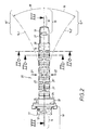
- FIG. 2 Between a lock cylinder 10, of which only a fragment of its rotor 11 is shown, and not shown in detail, arranged at 15 lock members a special shaft 20 is arranged.
- the shaft 20 is capable of transmitting an input torque, which is exerted on the rotor 11 and represented by the rotation arrow 12, into an output torque 13 indicated by the arrow 13.
- the shaft 20 is shown in the stretched state, which is expressed by the straight course of the shaft axis 14.
- the rotor shaft 16 is axially aligned with the shaft outlet 17.
- the shaft 20 by the angle 18 and 19 relative to the extended position 14 in all four directions 21 to 24 can be transferred into the curved course 14.1 to 14.4, as can be seen from Figures 2 and 3.
- the shaft 20 thus has the task, not only the axial distance between the lock cylinder 10 and the lock 15 and 15 'and 15 but also to compensate for a radial offset 18, 19 between the rotor axis 16 and the corresponding shaft outputs with respect to the lock members 15 'and 15 ", for which purpose the shaft 20 is designed in the following special way.
- the shaft 20 is made of bendable material 29. Of four each at right angles Notches 25, 25 'are inserted into the shaft 20 to mutually arranged sides 21 to 24. Namely, a pair 25, 25 'of such notches from two diametrically opposite sides 21, 22 and 23, 24 is introduced.
- notch pairs 25, 25 'webs 27 and 27' which are perpendicular to each other.
- the webs 27, 27 ' are arranged in the region of the shaft axis 14 and have a flat profile.
- the webs 27, 27 ' have a radial length 28, 28', which practically corresponds to the diameter 30 of the shaft 20.
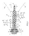
- a driver 31 for actuating the lock 15. It has the shape of a paddle.
- a terminal 32 for the cylinder core 11 of the lock cylinder 10 is provided at the outer end of the shaft.
- the terminal 32 has the shape of a housing shell.
- an overload member 33 is integrated, which is non-rotatable with the outlet 34 of the rotor 11.
- the rotor outlet 34 is also axially fixed to the housing port 32.
- the overload member 23 is also in connection with the connection 32 in a rotationally fixed connection, if the mentioned torques 12 are exerted on the rotor 11 via the inserted key, which are in any case below a certain threshold value.
- this threshold is exceeded and the overload member 33 set in free-running with respect to the terminal 32. As a result, violent rotations of the rotor 11 are not transmitted to the shaft 20.
- the webs 27, 27 ' ensure a good bending ability of the shaft 20 and act as bending points, which can be clearly seen with reference to FIG. 3.
- the webs 27 and 27 ' have a relatively small thickness 39, 39'.
- a bending stress of the shaft in the direction of the bending line 14.4 results, because the flanks 26 of the notches 25 move away from each other in the direction of the arrows 37, 37 '.
- the opposite movement takes place at the diametrically opposite notch 25 '.
- the two flanks 26 ', 26' in the direction of the arrows 38, 38 ' moved towards each other.
- the web 27 ' acts like a "film hinge".
- the flat profile 28, 39 or 28 ', 39' of the two webs 27, 27 ' is sufficient to transmit said torques 12 in the region of the rotor 11 to the shaft outlet 17.
- the output torque 13 is substantially equal to the input torque 12.
- a torsional slip of the shaft 20 does not take place because of the maximum possible large web length 28, 28 '.
Abstract
Description
Die Erfindung richtet sich auf eine Betätigungsvorrichtung der im Oberbegriff von Anspruch 1 genannten Art. Während der Schließzylinder mit seinem Stirnende für den Schlüssel von der Außenseite aus zugänglich ist, befindet sich das Schloss im Türinneren. Der Schließzylinder besteht aus einem schlüsselbetätigbaren Rotor, der in einem ortsfesten Stator der Tür drehgelagert ist. Die im Oberbegriff von Anspruch 1 genannte Welle hat die Aufgabe, das auf den Rotor des Schließzylinders ausgeübte Drehmoment auf die Schlossglieder zu übertragen. Dabei kommt es häufig vor, dass die Achse des zylinderseitigen Rotors nicht nur gegenüber der Drehachse zur Betätigung der Schlossglieder axial beabstandet, sondern auch radial versetzt ist.The invention is directed to an actuator of the type mentioned in the preamble of claim 1. While the lock cylinder is accessible with its front end for the key from the outside, the lock is located inside the door. The lock cylinder consists of a key-operated rotor, which is rotatably mounted in a fixed stator of the door. The wave mentioned in the preamble of claim 1 has the task of transmitting the torque exerted on the rotor of the lock cylinder to the lock members. It often happens that the axis of the cylinder-side rotor not only axially spaced from the axis of rotation for actuating the lock members, but also radially offset.
Es ist eine Betätigungsvorrichtung bekannt, (DE 195 27 837 C 2), bei welcher die Welle aus einer starren Stange mit endseitigen Gelenkteilen bestehen, welche zum zylinderseitigen Rotor hin einerseits und zu den Schlossgliedern andererseits jeweils Bestandteil von zwei Kardangelenken sind. Wenn die Orte des Schlosses und der Schließzylinder vorgegeben sind, ist der Verlauf der gradlinigen Welle im Türinneren festgelegt. Ein solcher Wellenverlauf kann aber mit dazwischen liegenden Türelementen kollidieren oder die Montage und Demontage von Tür- oder Schlosselementen erschweren.It is known an actuator (DE 195 27 837 C 2), in which the shaft consists of a rigid rod with end joint parts, which are the cylinder-side rotor on the one hand and the lock links on the other hand each part of two universal joints. If the locations of the lock and the lock cylinder are given, the course of the straight-line shaft is set inside the door. However, such a waveform can collide with intervening door elements or complicate the assembly and disassembly of door or lock elements.
Günstiger ist dann eine Vorrichtung der im Oberbegriff in Anspruch 1 angegebenen Art (FR 1 175 848 oder DE 196 49 905 C 2). Hier wird eine biegsame Welle verwendet, die zwischen der Achse des Schließzylinders und der Achse der Schlossglieder einen beliebigen bogenförmigen Verlauf einnehmen kann. Diese bekannte Welle besteht aus einem gewendelten Draht. Je leichter die Welle verbogen werden soll, um so dünner muss die Drehstärke und/oder nachgiebiger das Drahtmaterial gewählt werden. Das kann bei der Übertragung des Drehmomentes zu einem Torsionsschlupf zwischen den beiden Enden der Drahtwendel führen. Dies gilt insbesondere dann, wenn die Drehmomente gegen einen die Drehung behindernden großen Widerstand ausgeführt werden müssen.Cheaper then is a device specified in the preamble in claim 1 type (FR 1 175 848 or DE 196 49 905 C2). Here, a flexible shaft is used, which can take any arcuate course between the axis of the lock cylinder and the axis of the lock links. This known wave consists of a coiled wire. The easier the shaft is to be bent, the thinner the rotational strength and / or more compliant the wire material must be. This can result in the transmission of torque to a torsional slip between the two ends of the wire helix. This is especially true when the torques must be performed against a large resistance hindering the rotation.
Es ist bei einem rohrförmigen Längselement zur Übertragung von Kräften bekannt (EP 0 889 252 A2) abwechselnd von verschiedenen Seiten nur einen einzigen Einschnitt in die Rohrwand einzulassen, wodurch in der gegenüberliegenden Rohrwand ein Kreissegment verbleibt.It is in a tubular longitudinal element for the transmission of forces known (EP 0 889 252 A2) alternately from different sides only a single incision in the pipe wall to admit, whereby in the opposite pipe wall, a circular segment remains.
Der Erfindung liegt die Aufgabe zugrunde, eine preiswerte zuverlässige Vorrichtung der im Oberbegriff von Anspruch 1 genannten Art zu entwickeln, welche bei guter Übertragung von Drehmomenten die Biegsamkeit der Welle verbessert. Dies wird erfindungsgemäß durch die im Anspruch 1 angegebenen Maßnahmen erreicht, denen folgende besondere Bedeutung zukommt.The invention has for its object to develop a low-cost reliable device referred to in the preamble of claim 1, which improves the flexibility of the shaft with good transmission of torque. This is inventively achieved by the measures specified in claim 1, which have the following special significance.
Die von gegenüberliegenden Seiten in die Welle paarweise eingelassenen Kerben lassen im Bereich der Wellenachse jeweils einen Steg entstehen, der sich mit seiner Steglänge im wesentlichen über den ganzen Durchmesser der Welle erstreckt. Das ist für die Übertragung von Drehmomenten günstig. Weil die Kerben von diametral gegenüberliegenden Seiten in die Welle eingelassen sind, verbleiben zwischen den Stegen ein axial durchlaufender Kern in der Welle, der die gute Biegsamkeit ebenso fördert, wie die im wesentlichen zueinander parallel und radial zur Wellenachse verlaufenden Flanken der Kerben-Paare. Diese parallelen Flanken können nämlich bei der Biegebeanspruchung aufeinander zu und voneinander weg bewegt werden, wodurch auch kleine Biegeradien in der erfindungsgemäßen Biegewelle erzeugt werden können. Die Herstellung derartiger Biegewellen aus biegsamen Kunststoff ist sehr einfach und lässt sich ohne Weiteres im Spritzgussverfahren herstellen. An den Enden der erfindungsgemäßen Biegewelle ist ein Mitnehmer zur Betätigung des Schlosses und/oder ein Anschluss für den Schließzylinder einstückig mit der Welle ausgebildet.The notches embedded in pairs from opposite sides into the shaft can be made in the region of the shaft axis in each case a web which extends with its web length substantially over the entire diameter of the shaft. This is favorable for the transmission of torques. Because the notches are recessed from diametrically opposite sides into the shaft, an axially continuous core remains in the shaft between the webs which promotes good flexibility as well as the flanks of the notch pairs substantially parallel to each other and radial to the shaft axis. Namely, these parallel flanks can be moved towards and away from each other in the bending stress, whereby even small bending radii can be generated in the bending shaft according to the invention. The production of such bending waves made of flexible plastic is very simple and can be easily produced by injection molding. At the ends of the bending shaft according to the invention, a driver for actuating the lock and / or a connection for the lock cylinder is formed integrally with the shaft.
Weitere Maßnahmen und Vorteile der Erfindung ergeben sich aus den Unteransprüchen, der nachfolgenden Beschreibung und den Zeichnungen. In den Zeichnungen ist die Erfindung in einem Ausführungsbeispiel dargestellt. Es zeigen:
- Fig. 1,
- in Vergrößerung, die erfindungsgemäße Welle in perspektivischer Darstellung, wobei ein Anschluss für den Schließzylinder und ein Mitnehmer zur Betätigung des Schlosses gleich angeformt worden sind,
- Fig. 2
- die Draufsicht auf die Welle von Fig. 1,
- Fig. 2a + 2b
- zwei Querschnitte durch die Welle von Fig. 2 längs der dortigen Schnittlinien IIa - IIa bzw. IIb - IIb,
- Fig. 3
- einen Längsschnitt durch die Welle von Fig. 2 längs der dortigen Schnittlinie III - III.
- Fig. 1,
- in magnification, the shaft according to the invention in a perspective view, wherein a connection for the lock cylinder and a driver for actuating the lock have been formed the same,
- Fig. 2
- the plan view of the shaft of Fig. 1,
- Fig. 2a + 2b
- 2 cross sections through the shaft of FIG. 2 along the section lines IIa - IIa and IIb - IIb there,
- Fig. 3
- a longitudinal section through the shaft of Fig. 2 along the section line III - III.
Es wird zunächst auf Fig. 2 Bezug genommen. Zwischen einem Schließzylinder 10, von dem lediglich ein Bruchstück seines Rotors 11 gezeigt ist, und nicht näher gezeigten, bei 15 angeordneten Schlossgliedern ist eine besondere Welle 20 angeordnet. Die Welle 20 ist in der Lage, ein am Rotor 11 ausgeübtes, durch den Drehpfeil 12 veranschaulichtes Eingangs-Drehmoment in ein durch den Pfeil 13 verdeutlichtes Ausgangs-Drehmoment 13 zu übertragen. In allen Figuren ist die Welle 20 in gestrecktem Zustand dargestellt, was durch den geradlinigen Verlauf der Wellenachse 14 zum Ausdruck kommt. In diesem Fall ist die Rotorwelle 16 mit dem Wellenausgang 17 axial ausgerichtet. Wenn die Schlossglieder 15 aber eine gegenüber der Rotorwelle 16 nicht nur axial beabstandete sondern auch radial versetzte Lage bei 15' bzw. 15" einnehmen, dann kann die Welle 20 um den Winkel 18 bzw. 19 gegenüber der Strecklage 14 in alle vier Richtungen 21 bis 24 in den bogenförmigen Verlauf 14.1 bis 14.4 überführt werden, wie aus Fig. 2 und 3 zu erkennen ist. Die Welle 20 hat also die Aufgabe, nicht nur den axialen Abstand zwischen dem Schließzylinder 10 und dem Schloss 15 bzw. 15' bzw. 15" zu überbrücken, sondern auch einen radialen Versatz 18, 19 zwischen der Rotorachse 16 und den entsprechenden Wellenausgängen gegenüber den Schlossgliedern 15' und 15" auszugleichen. Dazu ist die Welle 20 in folgender besonderer Weise ausgebildet.Reference is first made to FIG. 2. Between a
Die Welle 20 besteht aus biegefähigem Material 29. Von jeweils vier rechtwinklig zueinander angeordneten Seiten 21 bis 24 werden Kerben 25, 25' in die Welle 20 eingelassen. Und zwar wird jeweils ein Paar 25, 25' solcher Kerben von zwei einander diametral gegenüberliegenden Seiten 21, 22 und 23, 24 eingebracht. Die Kerben 25, 25' verlaufen senkrecht zur gestreckten Wellenachse 14 und besitzen zueinander im wesentlichen parallel verlaufende Flanken 26, 26 bzw. 26', 26'.The
Wie aus den Querschnitten von Fig. 2a und 2b zu erkennen ist, entstehen zwischen den Kerben-Paaren 25, 25' Stege 27 bzw. 27', die zueinander senkrecht stehen. Die Stege 27, 27' sind im Bereich der Wellenachse 14 angeordnet und weisen ein Flachprofil auf. Dadurch haben die Stege 27, 27' eine radiale Länge 28, 28', die praktisch dem Durchmesser 30 der Welle 20 entspricht. Zwischen aufeinanderfolgenden Kerben-Paaren 25, 25', die abwechselnd von diametral gegenüberliegenden Seiten 21, 22 und 23, 24 eingebracht worden sind, verbleiben axiale Zwischenstücke 40, die vollen Wellenquerschnitt aufweisen.As can be seen from the cross sections of Fig. 2a and 2b, arise between the
An beiden Wellenenden sind die einerseits mit dem Rotor 11 und andererseits mit dem Schloss 5 zusammenwirkenden Elemente einstückig aus dem gleichen Kunststoffmaterial 29 angeformt. So befindet sich am Wellen-Innenende ein Mitnehmer 31 zur Betätigung des Schlosses 15. Es hat die Form eines Paddels. Am Außenende der Welle ist ein Anschluss 32 für den Zylinderkern 11 des Schließzylinders 10 vorgesehen. Der Anschluss 32 hat die Form einer Gehäuseschale. In die Gehäuseschale dieses Anschlusses 32 ist ein Überlastglied 33 integriert, welches drehfest mit dem Abgang 34 des Rotors 11 ist. Der Rotor-Abgang 34 ist außerdem axialfest mit dem Gehäuse-Anschluss 32 verbunden. Dazu dient ein aus Fig. 3 ersichtlicher Sprengring 35, der in eine hinterschnittene Ringnut 36 eingreift. Das Überlastglied 23 ist aber auch mit dem Anschluss 32 in drehfester Verbindung, wenn auf den Rotor 11 über den steckenden Schlüssel die erwähnten Drehmomente 12 ausgeübt werden, die in jedem Fall unter eines bestimmten Schwellenwertes liegen. Wenn die Welle 20 mittels Einbruchswerkzeuge manipuliert wird, wird dieser Schwellenwert überschritten und das Überlastglied 33 in Freilauf gegenüber dem Anschluss 32 gesetzt. Dadurch werden gewaltsame Drehungen des Rotors 11 nicht auf die Welle 20 übertragen.At both shaft ends, on the one hand with the
Die Stege 27, 27' sorgen für eine gute Biegefähigkeit der Welle 20 und fungieren als Biegestellen, was anhand der Fig. 3 gut zu erkennen ist. Wie aus Fig. 2a, 2b hervorgeht, besitzen die Stege 27 bzw. 27' eine verhältnismäßig geringe Dicke 39, 39'. Eine Biegebeanspruchung der Welle in Richtung der Biegelinie 14.4 ergibt sich, weil die Flanken 26 der Kerben 25 sich im Sinne der Pfeile 37, 37' voneinander wegbewegen. Es findet hier eine Aufklappbewegung der Flanken 26 an den Stegen 27' statt. Die gegensinnige Bewegung findet dabei an der diametral gegenüberliegenden Kerbe 25' statt. Hier werden bei der Biegung im Sinne der Biegelinie 14.4 von Fig. 3 die beiden Flanken 26', 26' im Sinne der Pfeile 38, 38' aufeinander zubewegt. Der Steg 27' wirkt wie ein "Filmscharnier".The
Dennoch ist das Flachprofil 28, 39 bzw. 28', 39' der beiden Stege 27, 27' ausreichend, um die genannten Drehmomente 12 im Bereich des Rotors 11 auf den Wellenausgang 17 zu übertragen. Das Ausgangs-Drehmoment 13 ist dem Eingangs-Drehmoment 12 im wesentlichen gleich. Ein Torsionsschlupf der Welle 20 findet wegen der maximal möglichen großen Steglänge 28, 28' nicht statt.Nevertheless, the
Bei einer im Sinne der Biegelinie 14.3 von Fig. 3 erfolgenden Biegebeanspruchung der Welle 20 ergeben sich bei den Flanken 26, 26' der beiden Kerben 25, 25' die spiegelbildlichen Verhältnisse. Die Kerbflanken 26 werden im Sinne der Pfeile 38, 38' von Fig. 3 gegeneinander geklappt, während die gegenüberliegenden Kerbflanken 26', 26' eine Aufklappbewegung im Sinne der Pfeile 37, 37' erfahren. Das Entsprechende geschieht, wenn die Biegebeanspruchungen im Sinne der beiden weiteren Biegelinien 14.1 und 14.2 von Fig. 2 erfolgen.In a bending stress of the
- 1010
- Schließzylinderlock cylinder
- 1111
- Rotorrotor
- 1212
- Eingangs-Drehmoment von 20Input torque of 20
- 1313
- Ausgangs-Drehmoment von 20Output torque of 20
- 1414
- Wellenachse von 20Shaft axis of 20
- 14.114.1
- Biegeverlauf von 14 in Richtung 21 (Fig. 2)Bending curve from 14 towards 21 (FIG. 2)
- 14.214.2
- Biegeverlauf von 14 in Richtung 22 (Fig. 2)Bending curve from 14 in the direction 22 (FIG. 2)
- 14.314.3
- Biegeverlauf von 14 in Richtung 23 (Fig. 3)Bending curve from 14 in direction 23 (FIG. 3)
- 14.414.4
- Biegeverlauf von 14 in Richtung 24 (Fig. 3)Bending curve from 14 in direction 24 (FIG. 3)
- 1515
- Lage der Schlossglieder, ausgerichtet (Fig. 2)Position of the lock links aligned (FIG. 2)
- 15'15 '
- Lage von 15 nach oben versetzt (Fig. 2)Position offset from 15 upwards (Fig. 2)
- 15"15 "
- Lage von 15 nach unten versetzt (Fig. 2)Position offset from 15 down (Fig. 2)
- 1616
- Rotorwelle von 11Rotor shaft of 11
- 1717
- Wellenausgang von 20, Innenende von 14Wave output of 20, inner end of 14
- 1818
- erster Winkel von 14' gegenüber 14 (Fig. 2)first angle of 14 'to 14 (Figure 2)
- 1919
- zweiter Winkel von 14" gegenüber 14 (Fig. 2)second angle of 14 "versus 14 (Figure 2)
- 2020
- Wellewave
- 2121
- obere Seite von 20 für 25upper side of 20 for 25
- 2222
- untere Seite von 20 für 25'lower side of 20 for 25 '
- 2323
- linke Seite von 20 für 25left side of 20 for 25
- 2424
- rechte Seite von 20 für 25'right side of 20 for 25 '
- 25, 25'25, 25 '
- Kerbe bei 21, 23 bzw. 22, 24Score at 21, 23 or 22, 24
- 26, 26'26, 26 '
- Flanke von 25 bzw. 25'Edge of 25 or 25 '
- 27, 27'27, 27 '
- Steg zwischen 25, 25 bzw. 25', 25'Bridge between 25, 25 or 25 ', 25'
- 2828
- Radiallänge von 27, Flachprofil von 27Radial length of 27, flat profile of 27
- 28'28 '
- Radiallänge von 27', Flachprofil von 27'Radial length of 27 ', flat profile of 27'
- 2929
- biegefähiges Kunststoffmaterial von 20bendable plastic material of 20
- 3030
- Durchmesser von 20Diameter of 20
- 3131
- Mitnehmer an 20 für 15Driver at 20 for 15
- 3232
- Anschluss an 20 für 11Connecting to 20 for 11
- 3333
- Überlastglied bei 32Overload member at 32
- 3434
- Abgang von 11Departure of 11
- 3535
- Sprengring bei 34 (Fig. 3)Snap ring at 34 (FIG. 3)
- 3636
- Ringnut in 32 (Fig. 3)Annular groove in 32 (FIG. 3)
- 37, 37'37, 37 '
- Pfeil der Aufklappbewegung von 26 bzw. 26' (Fig. 3)Arrow of the unfolding movement of 26 or 26 '(FIG. 3)
- 38, 38'38, 38 '
- Pfeil der Zuklappbewegung von 26 bzw. 26' (Fig. 3)Arrow of the closing movement of 26 or 26 '(FIG. 3)
- 39, 39'39, 39 '
- Dicke von 27, 27', FlachprofilThickness of 27, 27 ', flat profile
- 4040
- axiales Zwischenstück von 20axial intermediate piece of 20
Claims (3)
- Actuating device for a lock in a door or hatch of a motor vehicle,- with a lock cylinder (10), which has a lock (15) located a certain axial distance away and a shaft (20) extending between it and the lock;- which shaft transmits (13) a torque (12) to the lock (15) when the lock cylinder (10)is rotated;- where the shaft (20) is flexible (14.1 to 14.4) in its axial direction (14) to compensate for a radial offset (18, 19) between the axis (16) of the lock cylinder (10) and the lock (15), characterised in that- the one-piece shaft (20) is made of flexible material (29) and has a set of notches (25, 25') extending transversely to the axis (14) of the shaft;- which notches are recessed in pairs (25, 25') into the shaft (20) from diametrically opposing sides (21, 22 and 23, 24); in that- when the shaft (20) is stretched out straight, the two flanks (26, 26; 26', 26') of the notches (25, 25') are essentially parallel to each other and extend radially with respect to the axis (14) of the shaft; in that- the pairs of notches (25, 26') leave a web (27, 27') in the shaft (20) between their flanks (26, 26; 26', 26');- which web is located in the region of the axis (14) of the shaft and extends essentially across the entire diameter (30) of the shaft (20); in that- the webs (27, 27') produce flex points, at which, when bending load is exerted on the shaft (20), the two flanks (26, 26; 26', 26') of the pairs of notches (25, 25') can swing toward (38, 38') or away (37, 37') from each other; in that- intermediate axial pieces (40), extending in the axial direction (14) of the shaft and with the full cross section of the shaft (40), remain between successive pairs of diametrically opposing notches (25, 25'); and in that- a driver (31) for actuating the lock (15 or 15' or 15") and/or a connection (32) for the lock cylinder (10) is formed integrally on the shaft (20).
- Device according to claim 1, characterised in that the driver (31) has the form of a paddle.
- Device according to claim 1 or claim 2, characterised in that an overload element (33) is integrated into the connection (32),- which overload element, when the lock cylinder (10) is actuated as normal by the key, ensures a nonrotatable connection between the cylinder core (11) and the connection (32) at the outer end of the shaft (20), but also in that,- when the lock cylinder (10) is actuated forcibly by means of a break-in tool, as a result of which a specific torque limit is exceeded, the overload element (33) lets the cylinder core (11) and the driver (31) for the lock (15) rotate freely with respect to each other.
Applications Claiming Priority (3)
| Application Number | Priority Date | Filing Date | Title |
|---|---|---|---|
| DE10260076 | 2002-12-19 | ||
| DE10260076 | 2002-12-19 | ||
| PCT/EP2003/011888 WO2004057136A1 (en) | 2002-12-19 | 2003-10-25 | Operating device for a lock for doors or bonnets on a motor vehicle |
Publications (2)
| Publication Number | Publication Date |
|---|---|
| EP1573155A1 EP1573155A1 (en) | 2005-09-14 |
| EP1573155B1 true EP1573155B1 (en) | 2006-08-16 |
Family
ID=32667524
Family Applications (1)
| Application Number | Title | Priority Date | Filing Date |
|---|---|---|---|
| EP03788969A Expired - Lifetime EP1573155B1 (en) | 2002-12-19 | 2003-10-25 | Operating device for a lock for doors or bonnets on a motor vehicle |
Country Status (7)
| Country | Link |
|---|---|
| US (1) | US20060101879A1 (en) |
| EP (1) | EP1573155B1 (en) |
| KR (1) | KR100923184B1 (en) |
| CN (1) | CN100564780C (en) |
| AT (1) | ATE336629T1 (en) |
| DE (1) | DE50304689D1 (en) |
| WO (1) | WO2004057136A1 (en) |
Cited By (1)
| Publication number | Priority date | Publication date | Assignee | Title |
|---|---|---|---|---|
| EP2048307A2 (en) | 2007-10-12 | 2009-04-15 | Huf Hülsbeck & Fürst GmbH & Co. KG | Actuation device for a lock on vehicle doors, vehicle hatches or similar |
Families Citing this family (5)
| Publication number | Priority date | Publication date | Assignee | Title |
|---|---|---|---|---|
| NL1028885C2 (en) * | 2005-04-27 | 2006-10-30 | Stenman Holland Nv | Bicycle lock. |
| US7775071B2 (en) * | 2006-11-02 | 2010-08-17 | Inner-Tite Corp. | Pre-loaded barrel lock |
| US8939477B2 (en) | 2011-04-22 | 2015-01-27 | Schlage Lock Company | Clutch mechanism for a lock assembly |
| FR3102729B1 (en) * | 2019-11-05 | 2021-12-31 | Valeo Iluminacion Sa | VEHICLE LIGHTING DEVICE WITH OPTICAL AXIS ADJUSTMENT |
| CN111515966B (en) * | 2020-04-17 | 2022-04-19 | 中科开创(广州)智能科技发展有限公司 | Lightweight inspection robot with multiple degrees of freedom |
Family Cites Families (14)
| Publication number | Priority date | Publication date | Assignee | Title |
|---|---|---|---|---|
| DE925027C (en) * | 1952-07-03 | 1955-03-10 | Hermann Dipl-Ing Seidl | Flexible shaft |
| FR1175848A (en) * | 1957-05-29 | 1959-04-02 | Neiman Exploitation Brevets | Locking control by a barrel for automobile doors and trunks |
| NL6408413A (en) * | 1964-07-23 | 1966-01-24 | ||
| US3869877A (en) * | 1971-06-03 | 1975-03-11 | George R Brahler | Drive shaft |
| US5325845A (en) * | 1992-06-08 | 1994-07-05 | Adair Edwin Lloyd | Steerable sheath for use with selected removable optical catheter |
| DE19509116C2 (en) * | 1995-03-16 | 2000-01-05 | Deutsch Zentr Luft & Raumfahrt | Flexible structure |
| DE19527837C2 (en) * | 1995-07-29 | 2000-09-28 | Kiekert Ag | Motor vehicle door lock system with lock unit and lock cylinder / handle unit |
| DE19649905C2 (en) * | 1996-12-02 | 2002-06-13 | Valeo Gmbh & Co Schliessyst Kg | Actuator for the door lock of a motor vehicle |
| DE29711559U1 (en) * | 1997-07-02 | 1997-08-21 | Howmedica Gmbh | Elongated element for the transmission of forces |
| US5894749A (en) * | 1997-09-03 | 1999-04-20 | Atoma International Corp. | Latching system with flexible release |
| DE10162201A1 (en) * | 2000-12-20 | 2002-07-11 | Tokai Rika Co Ltd | Key cylinder and method for assembling a key cylinder |
| DE10158383B4 (en) * | 2001-11-28 | 2004-11-18 | Huf Hülsbeck & Fürst Gmbh & Co. Kg | Closure for a flap, a drawer or a lid, especially in vehicles |
| FR2833662B1 (en) * | 2001-12-17 | 2004-02-27 | Valeo Climatisation | SINGLE-MATERIAL REMOTE CONTROL DEVICE |
| DE10246501A1 (en) * | 2002-10-04 | 2004-04-15 | Dr.Ing.H.C. F. Porsche Ag | Door lock of a motor vehicle |
-
2003
- 2003-10-25 KR KR1020057011492A patent/KR100923184B1/en active IP Right Grant
- 2003-10-25 US US10/538,968 patent/US20060101879A1/en not_active Abandoned
- 2003-10-25 AT AT03788969T patent/ATE336629T1/en not_active IP Right Cessation
- 2003-10-25 DE DE50304689T patent/DE50304689D1/en not_active Expired - Fee Related
- 2003-10-25 EP EP03788969A patent/EP1573155B1/en not_active Expired - Lifetime
- 2003-10-25 CN CNB2003801071396A patent/CN100564780C/en not_active Expired - Fee Related
- 2003-10-25 WO PCT/EP2003/011888 patent/WO2004057136A1/en active IP Right Grant
Cited By (3)
| Publication number | Priority date | Publication date | Assignee | Title |
|---|---|---|---|---|
| EP2048307A2 (en) | 2007-10-12 | 2009-04-15 | Huf Hülsbeck & Fürst GmbH & Co. KG | Actuation device for a lock on vehicle doors, vehicle hatches or similar |
| DE102007049068A1 (en) | 2007-10-12 | 2009-04-16 | Huf Hülsbeck & Fürst Gmbh & Co. Kg | Actuating device for a lock on vehicle doors, vehicle doors or the like. |
| EP2048307A3 (en) * | 2007-10-12 | 2010-08-11 | Huf Hülsbeck & Fürst GmbH & Co. KG | Actuation device for a lock on vehicle doors, vehicle hatches or similar |
Also Published As
| Publication number | Publication date |
|---|---|
| KR20050085816A (en) | 2005-08-29 |
| EP1573155A1 (en) | 2005-09-14 |
| CN1729340A (en) | 2006-02-01 |
| DE50304689D1 (en) | 2006-09-28 |
| WO2004057136A1 (en) | 2004-07-08 |
| KR100923184B1 (en) | 2009-10-22 |
| ATE336629T1 (en) | 2006-09-15 |
| CN100564780C (en) | 2009-12-02 |
| US20060101879A1 (en) | 2006-05-18 |
Similar Documents
| Publication | Publication Date | Title |
|---|---|---|
| DE602005001818T2 (en) | Clutch mechanism for locks | |
| EP1845299B1 (en) | Connecting device for a pipe | |
| EP1098063B1 (en) | Tubular motor | |
| WO2008043600A1 (en) | Coupling device | |
| EP2504258A2 (en) | Drum motor having a profiled casing | |
| EP1573155B1 (en) | Operating device for a lock for doors or bonnets on a motor vehicle | |
| DE19736770C2 (en) | Soundproof driver for a tubular motor of a winding shaft for a roller shutter | |
| EP2058461B1 (en) | Driving rod gear | |
| EP0823543B1 (en) | Chain drive unit for an internal combustion engine | |
| EP1245889A1 (en) | Pipe clamp | |
| EP2048307B1 (en) | Actuation device for a lock on vehicle doors, vehicle hatches or similar | |
| EP1760250A2 (en) | Actuation assembly for roller shutters | |
| EP2469011B1 (en) | Tubular motor for a darkening device or similar | |
| EP1416109B1 (en) | Actuating device for a vehicle lock of door or lid | |
| EP2466163A2 (en) | Load torsional block for a gear drive unit and device with the same | |
| EP1405971B1 (en) | Lock for a door of a motor vehicle | |
| DE102019118338A1 (en) | Torque drive head | |
| WO1998023883A1 (en) | Planetary gear, to be used specially in bore holes | |
| EP3795785A1 (en) | Lock and key system | |
| DE10141672C1 (en) | Fluid line or cable holder, for automobile, has projections around fluid line or cable cooperating with gaps between projections of holder for fixing relative angular position | |
| DE10232184A1 (en) | Transmission unit for vehicle door locks has intermediate plate, locking pawl carrier and bolt, levers, leg springs, thrust piece, protuberance and bearing sleeve | |
| EP0766794A1 (en) | Coupling device | |
| DE19911894A1 (en) | Espagnolette locking mechanism has driving rod, slip bar fixed to housing, pinion, teeth, holes drive bolt and inserted sheet metal strip | |
| DE19820080A1 (en) | Installation of a choke disc in the inlet manifold of motor vehicle | |
| DE10238703B4 (en) | Actuating device of an adjusting device of a motor vehicle seat |
Legal Events
| Date | Code | Title | Description |
|---|---|---|---|
| PUAI | Public reference made under article 153(3) epc to a published international application that has entered the european phase |
Free format text: ORIGINAL CODE: 0009012 |
|
| 17P | Request for examination filed |
Effective date: 20050523 |
|
| AK | Designated contracting states |
Kind code of ref document: A1 Designated state(s): AT BE BG CH CY CZ DE DK EE ES FI FR GB GR HU IE IT LI LU MC NL PT RO SE SI SK TR |
|
| GRAP | Despatch of communication of intention to grant a patent |
Free format text: ORIGINAL CODE: EPIDOSNIGR1 |
|
| GRAS | Grant fee paid |
Free format text: ORIGINAL CODE: EPIDOSNIGR3 |
|
| GRAA | (expected) grant |
Free format text: ORIGINAL CODE: 0009210 |
|
| AK | Designated contracting states |
Kind code of ref document: B1 Designated state(s): AT BE BG CH CY CZ DE DK EE ES FI FR GB GR HU IE IT LI LU MC NL PT RO SE SI SK TR |
|
| PG25 | Lapsed in a contracting state [announced via postgrant information from national office to epo] |
Ref country code: IT Free format text: LAPSE BECAUSE OF FAILURE TO SUBMIT A TRANSLATION OF THE DESCRIPTION OR TO PAY THE FEE WITHIN THE PRESCRIBED TIME-LIMIT;WARNING: LAPSES OF ITALIAN PATENTS WITH EFFECTIVE DATE BEFORE 2007 MAY HAVE OCCURRED AT ANY TIME BEFORE 2007. THE CORRECT EFFECTIVE DATE MAY BE DIFFERENT FROM THE ONE RECORDED. Effective date: 20060816 Ref country code: SK Free format text: LAPSE BECAUSE OF FAILURE TO SUBMIT A TRANSLATION OF THE DESCRIPTION OR TO PAY THE FEE WITHIN THE PRESCRIBED TIME-LIMIT Effective date: 20060816 Ref country code: SI Free format text: LAPSE BECAUSE OF FAILURE TO SUBMIT A TRANSLATION OF THE DESCRIPTION OR TO PAY THE FEE WITHIN THE PRESCRIBED TIME-LIMIT Effective date: 20060816 Ref country code: NL Free format text: LAPSE BECAUSE OF FAILURE TO SUBMIT A TRANSLATION OF THE DESCRIPTION OR TO PAY THE FEE WITHIN THE PRESCRIBED TIME-LIMIT Effective date: 20060816 Ref country code: IE Free format text: LAPSE BECAUSE OF FAILURE TO SUBMIT A TRANSLATION OF THE DESCRIPTION OR TO PAY THE FEE WITHIN THE PRESCRIBED TIME-LIMIT Effective date: 20060816 Ref country code: FI Free format text: LAPSE BECAUSE OF FAILURE TO SUBMIT A TRANSLATION OF THE DESCRIPTION OR TO PAY THE FEE WITHIN THE PRESCRIBED TIME-LIMIT Effective date: 20060816 Ref country code: RO Free format text: LAPSE BECAUSE OF FAILURE TO SUBMIT A TRANSLATION OF THE DESCRIPTION OR TO PAY THE FEE WITHIN THE PRESCRIBED TIME-LIMIT Effective date: 20060816 |
|
| REG | Reference to a national code |
Ref country code: GB Ref legal event code: FG4D Free format text: NOT ENGLISH |
|
| REG | Reference to a national code |
Ref country code: CH Ref legal event code: EP |
|
| REG | Reference to a national code |
Ref country code: IE Ref legal event code: FG4D Free format text: LANGUAGE OF EP DOCUMENT: GERMAN |
|
| REF | Corresponds to: |
Ref document number: 50304689 Country of ref document: DE Date of ref document: 20060928 Kind code of ref document: P |
|
| PG25 | Lapsed in a contracting state [announced via postgrant information from national office to epo] |
Ref country code: MC Free format text: LAPSE BECAUSE OF NON-PAYMENT OF DUE FEES Effective date: 20061031 |
|
| PG25 | Lapsed in a contracting state [announced via postgrant information from national office to epo] |
Ref country code: SE Free format text: LAPSE BECAUSE OF FAILURE TO SUBMIT A TRANSLATION OF THE DESCRIPTION OR TO PAY THE FEE WITHIN THE PRESCRIBED TIME-LIMIT Effective date: 20061116 Ref country code: DK Free format text: LAPSE BECAUSE OF FAILURE TO SUBMIT A TRANSLATION OF THE DESCRIPTION OR TO PAY THE FEE WITHIN THE PRESCRIBED TIME-LIMIT Effective date: 20061116 Ref country code: BG Free format text: LAPSE BECAUSE OF FAILURE TO SUBMIT A TRANSLATION OF THE DESCRIPTION OR TO PAY THE FEE WITHIN THE PRESCRIBED TIME-LIMIT Effective date: 20061116 |
|
| PG25 | Lapsed in a contracting state [announced via postgrant information from national office to epo] |
Ref country code: ES Free format text: LAPSE BECAUSE OF FAILURE TO SUBMIT A TRANSLATION OF THE DESCRIPTION OR TO PAY THE FEE WITHIN THE PRESCRIBED TIME-LIMIT Effective date: 20061127 |
|
| GBT | Gb: translation of ep patent filed (gb section 77(6)(a)/1977) |
Effective date: 20061122 |
|
| PG25 | Lapsed in a contracting state [announced via postgrant information from national office to epo] |
Ref country code: PT Free format text: LAPSE BECAUSE OF FAILURE TO SUBMIT A TRANSLATION OF THE DESCRIPTION OR TO PAY THE FEE WITHIN THE PRESCRIBED TIME-LIMIT Effective date: 20070116 |
|
| ET | Fr: translation filed | ||
| NLV1 | Nl: lapsed or annulled due to failure to fulfill the requirements of art. 29p and 29m of the patents act | ||
| REG | Reference to a national code |
Ref country code: IE Ref legal event code: FD4D |
|
| PG25 | Lapsed in a contracting state [announced via postgrant information from national office to epo] |
Ref country code: DE Free format text: LAPSE BECAUSE OF NON-PAYMENT OF DUE FEES Effective date: 20070501 |
|
| PLBE | No opposition filed within time limit |
Free format text: ORIGINAL CODE: 0009261 |
|
| STAA | Information on the status of an ep patent application or granted ep patent |
Free format text: STATUS: NO OPPOSITION FILED WITHIN TIME LIMIT |
|
| 26N | No opposition filed |
Effective date: 20070518 |
|
| BERE | Be: lapsed |
Owner name: HUF HULSBECK & FURST G.M.B.H. & CO. KG Effective date: 20061031 |
|
| PG25 | Lapsed in a contracting state [announced via postgrant information from national office to epo] |
Ref country code: AT Free format text: LAPSE BECAUSE OF NON-PAYMENT OF DUE FEES Effective date: 20061025 |
|
| PG25 | Lapsed in a contracting state [announced via postgrant information from national office to epo] |
Ref country code: GR Free format text: LAPSE BECAUSE OF FAILURE TO SUBMIT A TRANSLATION OF THE DESCRIPTION OR TO PAY THE FEE WITHIN THE PRESCRIBED TIME-LIMIT Effective date: 20061117 |
|
| REG | Reference to a national code |
Ref country code: CH Ref legal event code: PL |
|
| PG25 | Lapsed in a contracting state [announced via postgrant information from national office to epo] |
Ref country code: EE Free format text: LAPSE BECAUSE OF FAILURE TO SUBMIT A TRANSLATION OF THE DESCRIPTION OR TO PAY THE FEE WITHIN THE PRESCRIBED TIME-LIMIT Effective date: 20060816 |
|
| PG25 | Lapsed in a contracting state [announced via postgrant information from national office to epo] |
Ref country code: TR Free format text: LAPSE BECAUSE OF FAILURE TO SUBMIT A TRANSLATION OF THE DESCRIPTION OR TO PAY THE FEE WITHIN THE PRESCRIBED TIME-LIMIT Effective date: 20060816 Ref country code: LU Free format text: LAPSE BECAUSE OF NON-PAYMENT OF DUE FEES Effective date: 20061025 Ref country code: CH Free format text: LAPSE BECAUSE OF NON-PAYMENT OF DUE FEES Effective date: 20071031 Ref country code: HU Free format text: LAPSE BECAUSE OF FAILURE TO SUBMIT A TRANSLATION OF THE DESCRIPTION OR TO PAY THE FEE WITHIN THE PRESCRIBED TIME-LIMIT Effective date: 20070217 Ref country code: LI Free format text: LAPSE BECAUSE OF NON-PAYMENT OF DUE FEES Effective date: 20071031 |
|
| PG25 | Lapsed in a contracting state [announced via postgrant information from national office to epo] |
Ref country code: CY Free format text: LAPSE BECAUSE OF FAILURE TO SUBMIT A TRANSLATION OF THE DESCRIPTION OR TO PAY THE FEE WITHIN THE PRESCRIBED TIME-LIMIT Effective date: 20060816 |
|
| PG25 | Lapsed in a contracting state [announced via postgrant information from national office to epo] |
Ref country code: BE Free format text: LAPSE BECAUSE OF FAILURE TO SUBMIT A TRANSLATION OF THE DESCRIPTION OR TO PAY THE FEE WITHIN THE PRESCRIBED TIME-LIMIT Effective date: 20061031 |
|
| PGFP | Annual fee paid to national office [announced via postgrant information from national office to epo] |
Ref country code: GB Payment date: 20101025 Year of fee payment: 8 Ref country code: IT Payment date: 20101022 Year of fee payment: 8 |
|
| GBPC | Gb: european patent ceased through non-payment of renewal fee |
Effective date: 20111025 |
|
| PG25 | Lapsed in a contracting state [announced via postgrant information from national office to epo] |
Ref country code: IT Free format text: LAPSE BECAUSE OF NON-PAYMENT OF DUE FEES Effective date: 20111025 Ref country code: GB Free format text: LAPSE BECAUSE OF NON-PAYMENT OF DUE FEES Effective date: 20111025 |
|
| REG | Reference to a national code |
Ref country code: FR Ref legal event code: PLFP Year of fee payment: 13 |
|
| REG | Reference to a national code |
Ref country code: FR Ref legal event code: PLFP Year of fee payment: 14 |
|
| REG | Reference to a national code |
Ref country code: FR Ref legal event code: PLFP Year of fee payment: 15 |
|
| REG | Reference to a national code |
Ref country code: FR Ref legal event code: PLFP Year of fee payment: 16 |
|
| PGFP | Annual fee paid to national office [announced via postgrant information from national office to epo] |
Ref country code: CZ Payment date: 20200925 Year of fee payment: 18 |
|
| PGFP | Annual fee paid to national office [announced via postgrant information from national office to epo] |
Ref country code: FR Payment date: 20201023 Year of fee payment: 18 |
|
| PG25 | Lapsed in a contracting state [announced via postgrant information from national office to epo] |
Ref country code: CZ Free format text: LAPSE BECAUSE OF NON-PAYMENT OF DUE FEES Effective date: 20211025 |
|
| PG25 | Lapsed in a contracting state [announced via postgrant information from national office to epo] |
Ref country code: FR Free format text: LAPSE BECAUSE OF NON-PAYMENT OF DUE FEES Effective date: 20211031 |