EP1571872A1 - Ear-hook earphone with microphone - Google Patents
Ear-hook earphone with microphone Download PDFInfo
- Publication number
- EP1571872A1 EP1571872A1 EP04290617A EP04290617A EP1571872A1 EP 1571872 A1 EP1571872 A1 EP 1571872A1 EP 04290617 A EP04290617 A EP 04290617A EP 04290617 A EP04290617 A EP 04290617A EP 1571872 A1 EP1571872 A1 EP 1571872A1
- Authority
- EP
- European Patent Office
- Prior art keywords
- earphone
- microphone
- main body
- wire
- hook
- Prior art date
- Legal status (The legal status is an assumption and is not a legal conclusion. Google has not performed a legal analysis and makes no representation as to the accuracy of the status listed.)
- Withdrawn
Links
Images


Classifications
-
- H—ELECTRICITY
- H04—ELECTRIC COMMUNICATION TECHNIQUE
- H04R—LOUDSPEAKERS, MICROPHONES, GRAMOPHONE PICK-UPS OR LIKE ACOUSTIC ELECTROMECHANICAL TRANSDUCERS; DEAF-AID SETS; PUBLIC ADDRESS SYSTEMS
- H04R1/00—Details of transducers, loudspeakers or microphones
- H04R1/10—Earpieces; Attachments therefor ; Earphones; Monophonic headphones
- H04R1/1058—Manufacture or assembly
- H04R1/1066—Constructional aspects of the interconnection between earpiece and earpiece support
-
- H—ELECTRICITY
- H04—ELECTRIC COMMUNICATION TECHNIQUE
- H04R—LOUDSPEAKERS, MICROPHONES, GRAMOPHONE PICK-UPS OR LIKE ACOUSTIC ELECTROMECHANICAL TRANSDUCERS; DEAF-AID SETS; PUBLIC ADDRESS SYSTEMS
- H04R1/00—Details of transducers, loudspeakers or microphones
- H04R1/08—Mouthpieces; Microphones; Attachments therefor
- H04R1/083—Special constructions of mouthpieces
-
- H—ELECTRICITY
- H04—ELECTRIC COMMUNICATION TECHNIQUE
- H04R—LOUDSPEAKERS, MICROPHONES, GRAMOPHONE PICK-UPS OR LIKE ACOUSTIC ELECTROMECHANICAL TRANSDUCERS; DEAF-AID SETS; PUBLIC ADDRESS SYSTEMS
- H04R1/00—Details of transducers, loudspeakers or microphones
- H04R1/10—Earpieces; Attachments therefor ; Earphones; Monophonic headphones
- H04R1/1016—Earpieces of the intra-aural type
-
- H—ELECTRICITY
- H04—ELECTRIC COMMUNICATION TECHNIQUE
- H04R—LOUDSPEAKERS, MICROPHONES, GRAMOPHONE PICK-UPS OR LIKE ACOUSTIC ELECTROMECHANICAL TRANSDUCERS; DEAF-AID SETS; PUBLIC ADDRESS SYSTEMS
- H04R2201/00—Details of transducers, loudspeakers or microphones covered by H04R1/00 but not provided for in any of its subgroups
- H04R2201/10—Details of earpieces, attachments therefor, earphones or monophonic headphones covered by H04R1/10 but not provided for in any of its subgroups
- H04R2201/109—Arrangements to adapt hands free headphones for use on both ears
Definitions
- the present invention discloses an earphone with microphone, especially to an adjustable ear-hook earphone with microphone.
- An earphone with microphone combines both the function of the earphone with the microphone.
- the conventional earphones with microphone is classified into headworn type, in-ear type and ear-hook type.
- the headworn microphone is a headset earphone with a microphone extending from one side of the enclosure thereof.
- the headset is held on users' head only by the earphones on two ends of the frame without any other parts for securing.
- the earphone is easy to come off while the users are jumping or jerking their heads. Thus it is not fit for those in movement or with hats on their heads.
- the in-earphone for special agents is composed by an earphone inside the ear canal, a signal wire around users' neck, and a microphone clipped on the neck or shirtband. Due to the scattered parts, the device is difficult to use and store. Not only the earphone is easy to fall off but also the wire is easy to be broken. The position of the microphone is inconvenient to fix. Therefore, the device is unfitting for those who desire freedom of movement such as policemen and soldiers.
- the microphone is over-the-ear and is attached on users' ear by an auriform hook for communication. Compared with other types of earphones, such type microphone provides much firmly attachment. However, the shape of the ear-hook can't be adjusted for best fit and required comfort on users' ear.
- the microphone and the earphone are convenient to be adjusted for optimum placement and once being positioned, not come off easily.
- the present invention provides an adjustable ear-hook earphone with a microphone having a C-shaped hook with a sleeve on top end thereof, a wire entry, a wire exit, and a wire channel are arranged on upper part of the C-shaped hook in tangential direction.
- the main body of the earphone has a speaker mounted on lateral side and a limiting part extending from top side thereof.
- the outer diameter of the adjusting post is corresponding to the inner diameter of the sleeve so that the adjusting post is sleeved into the sleeve to allow the main body of earphone turning left or right in a certain angle as well as moving upwards or downwards for optimum placement.
- One end of a flexible tube is pivoted to the lateral side of the main body of earphone and is extending downwards while the other end thereof is connected with a microphone. The flexible tube swings to and fro. A signal wire passes through the entry, the wire channel, the wire exit, and then connects to the main body of earphone.
- the invention includes a C-shaped hook with a sleeve on top end thereof, a wire entry, a wire exit, and a wire channel are arranged on upper part of the C-shaped hook in tangential direction.
- the main body of the earphone has a speaker mounted on lateral side and a limiting part extending from top side thereof.
- An adjusting post is clipped on lateral side of the limiting part.
- the outer diameter of the adjusting post is corresponding to the inner diameter of the sleeve so as to insert the adjusting post into the sleeve and allow the main body of earphone turning right or left in a certain angle as well as moving upwards or downwards for optimum placement.
- the present invention relates to an ear-hook earphone with a microphone that is convenient for use and is perfect fit. According to users' need, the hook and the earphone adjust to any height and direction.
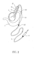
- the present invention is composed by a C-shaped hook 1 with a sleeve 11 on top end thereof, a wire entry 121, a wire exit 122, and a wire channel 123 are arranged on upper part of the C-shaped hook 1 in tangential direction, a main body of earphone 2 with a speaker 21 on lateral side and a limiting part 22 extending from top side thereof.
- An adjusting post 23 whose outer diameter is corresponding to the inner diameter of the sleeve 11 is clipped on side of the limiting part 22 and is sleeved into the sleeve 11 so as to allow the main body 2 moving upwards or downwards as well as turning right or left in a certain angle for optimum placement.
- a signal wire 3 inserts through the wire entry 121, the wire channel 123, the wire exit 122 and then connects with the main body 2 of earphone.
- the Fig.1 & Fig. 2 show the embodiments for applying on the right and left ear respectively.
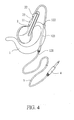
- the limiting part 22 of the main body of earphone 2 When being used, the limiting part 22 of the main body of earphone 2 further having a wire accommodating slot or channel (not shown in figure) for housing the signal wire 3 therein.
- the signal wire 3 is connected to the main body 2 through the wire accommodating slot or the adjusting post 23, as the embodiments shown in Fig. 3 & 4.
- the hollow channel (not shown in the figure) is mounted inside the adjusting post 23 for lodging the signal wire 3.
- the other end of the signal wire 3 is connected with a plug 4 (or an audio set).
- the Fig. 3 & Fig. 4 show the embodiments for applying on the right and left ear respectively.
- the structure of the present invention is simple and easy for assembling.
- the adjusting post 23 is sleeved in the C-shaped hook 1, then the speaker 21 is mounted in the slot of the main body of earphone 2.
- the main body of earphone 2 is fit on user's ear by the hook 1 firmly and the speaker 21 can be adjusted to optimum position.
- the signal wire 3 won't fall off as easy as that of a prior art.
- the signal wire 3 inserts into the wire entry 121, through the wire channel 123, extends out of the wire exit 122. There is friction between the signal wire 3 and the inner wall of the wire entry 121 as well as the wire exit 122 so as to prevent the wire 3 from being unset or broken. When there is a certain angle between the direction of the signal wire 3 being pulled and that of the wire entry 121 or the wire exit 122, the friction is larger.
- the main body of earphone 2 and the hook 1 are restricted by the limiting part 22 and the adjusting post 23 so as to prevent the rotation of the signal wire 3 between the hook 1 and the main body of earphone 2 in 360 degrees. This also avoids the tangling or breakage of the signal wire 3. Due to the limiting part 22 and the adjusting post 23, the main body of earphone 2 can be adjusted in 210 degrees corresponding to the hook 1 thus the present invention can be applied on the right or left ear according to user's needs.
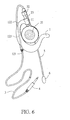
- Fig. 5 & Fig. 6 disclose a better embodiment of the present invention.
- the device includes a C-shaped hook 1 with a sleeve 11 on top end thereof, a wire entry 121, a wire exit 122, and a wire channel 123 are arranged on upper part of the C-shaped hook 1 in tangential direction, a main body of earphone 2 with a speaker 21 on lateral side and a limiting part 22 extending from top side thereof.
- An adjusting post 23 clipped on side of the limiting part 22 is sleeved in the sleeve 11 so as to move the main body 2 upwards or downwards, or turning right or left in a certain angle.
- a signal wire 3 inserts through the wire entry 121, the wire channel 123, the wire exit 122 and connects with the main body of earphone 2.
- a flexible tube 5 with one end pivoted to the lateral side of the main body of earphone 2 extends downwards and swings to-and-fro.
- a microphone 6 is disposed on the other end of the flexible tube 5 and is connected with the main body of earphone 2 by the flexible tube 5.
- the Fig. 5 & Fig. 6 show the above-mentioned embodiments for applying on the right and left ear respectively.
- the Fig. 7 & Fig. 8 show the above-mentioned embodiment being applied on users' right and left ear respectively.
Abstract
Description
- The present invention discloses an earphone with microphone, especially to an adjustable ear-hook earphone with microphone.
- An earphone with microphone combines both the function of the earphone with the microphone. The conventional earphones with microphone is classified into headworn type, in-ear type and ear-hook type. The headworn microphone is a headset earphone with a microphone extending from one side of the enclosure thereof. Although the placement of the microphone is adjustable and the earflaps are not so easy to fall off, such type is just suitable for static users. The headset is held on users' head only by the earphones on two ends of the frame without any other parts for securing. Moreover, the earphone is easy to come off while the users are jumping or jerking their heads. Thus it is not fit for those in movement or with hats on their heads.
- The in-earphone for special agents is composed by an earphone inside the ear canal, a signal wire around users' neck, and a microphone clipped on the neck or shirtband. Due to the scattered parts, the device is difficult to use and store. Not only the earphone is easy to fall off but also the wire is easy to be broken. The position of the microphone is inconvenient to fix. Therefore, the device is unfitting for those who desire freedom of movement such as policemen and soldiers.
- As to the ear-hook microphone, the microphone is over-the-ear and is attached on users' ear by an auriform hook for communication. Compared with other types of earphones, such type microphone provides much firmly attachment. However, the shape of the ear-hook can't be adjusted for best fit and required comfort on users' ear.
- Therefore, there is a need to provide an earphone with a microphone that is simple, easy for assembling and attaching, convenient to be adjusted and won't come off easily.
- It is a primary object of the present invention to provide an adjustable ear-hook earphone with a microphone whose structure is simple, easy for assembling and attaching. The microphone and the earphone are convenient to be adjusted for optimum placement and once being positioned, not come off easily.
- In order to achieve the object mentioned above, the present invention provides an adjustable ear-hook earphone with a microphone having a C-shaped hook with a sleeve on top end thereof, a wire entry, a wire exit, and a wire channel are arranged on upper part of the C-shaped hook in tangential direction. The main body of the earphone has a speaker mounted on lateral side and a limiting part extending from top side thereof. An adjusting post clipped on the lateral side of the limiting part. The outer diameter of the adjusting post is corresponding to the inner diameter of the sleeve so that the adjusting post is sleeved into the sleeve to allow the main body of earphone turning left or right in a certain angle as well as moving upwards or downwards for optimum placement. One end of a flexible tube is pivoted to the lateral side of the main body of earphone and is extending downwards while the other end thereof is connected with a microphone. The flexible tube swings to and fro. A signal wire passes through the entry, the wire channel, the wire exit, and then connects to the main body of earphone.
- It is a further object of the present invention to provides an adjustable ear-hook earphone with a microphone that is simple, easy for assembling and adjustment to the optimum placement, and convenient to use.
- The invention includes a C-shaped hook with a sleeve on top end thereof, a wire entry, a wire exit, and a wire channel are arranged on upper part of the C-shaped hook in tangential direction. The main body of the earphone has a speaker mounted on lateral side and a limiting part extending from top side thereof. An adjusting post is clipped on lateral side of the limiting part. The outer diameter of the adjusting post is corresponding to the inner diameter of the sleeve so as to insert the adjusting post into the sleeve and allow the main body of earphone turning right or left in a certain angle as well as moving upwards or downwards for optimum placement.
- The accomplishment of the above-mentioned object of the present invention will become apparent from the following description and its accompanying drawings which disclose illustrative an embodiment of the present invention, and are as follows:
- Fig. 1 & Fig. 2 show an embodiment of an adjustable ear-hook earphone in accordance with the present invention;
- Fig. 3 & Fig. 4 show another embodiment of an adjustable ear-hook earphone in accordance with the present invention;
- Fig. 5 & Fig. 6 show a further embodiment of an adjustable ear-hook earphone in accordance with the present invention;
- Fig. 7 & Fig. 8 show the present invention being applied on users' ear.
-
- The present invention relates to an ear-hook earphone with a microphone that is convenient for use and is perfect fit. According to users' need, the hook and the earphone adjust to any height and direction.
- Refer to Fig. 1 & Fig. 2, the present invention is composed by a C-
shaped hook 1 with asleeve 11 on top end thereof, awire entry 121, awire exit 122, and awire channel 123 are arranged on upper part of the C-shaped hook 1 in tangential direction, a main body ofearphone 2 with aspeaker 21 on lateral side and alimiting part 22 extending from top side thereof. An adjustingpost 23 whose outer diameter is corresponding to the inner diameter of thesleeve 11 is clipped on side of thelimiting part 22 and is sleeved into thesleeve 11 so as to allow themain body 2 moving upwards or downwards as well as turning right or left in a certain angle for optimum placement. Asignal wire 3 inserts through thewire entry 121, thewire channel 123, thewire exit 122 and then connects with themain body 2 of earphone. The Fig.1 & Fig. 2 show the embodiments for applying on the right and left ear respectively. - When being used, the limiting
part 22 of the main body ofearphone 2 further having a wire accommodating slot or channel (not shown in figure) for housing thesignal wire 3 therein. Thesignal wire 3 is connected to themain body 2 through the wire accommodating slot or the adjustingpost 23, as the embodiments shown in Fig. 3 & 4. The hollow channel (not shown in the figure) is mounted inside the adjustingpost 23 for lodging thesignal wire 3. The other end of thesignal wire 3 is connected with a plug 4 (or an audio set). The Fig. 3 & Fig. 4 show the embodiments for applying on the right and left ear respectively. - In accordance with the description mentioned above, the structure of the present invention is simple and easy for assembling. When being assembled, the adjusting
post 23 is sleeved in the C-shaped hook 1, then thespeaker 21 is mounted in the slot of the main body ofearphone 2. When being used, the main body ofearphone 2 is fit on user's ear by thehook 1 firmly and thespeaker 21 can be adjusted to optimum position. Thesignal wire 3 won't fall off as easy as that of a prior art. - Moreover, the
signal wire 3 inserts into thewire entry 121, through thewire channel 123, extends out of thewire exit 122. There is friction between thesignal wire 3 and the inner wall of thewire entry 121 as well as thewire exit 122 so as to prevent thewire 3 from being unset or broken. When there is a certain angle between the direction of thesignal wire 3 being pulled and that of thewire entry 121 or thewire exit 122, the friction is larger. - The main body of
earphone 2 and thehook 1 are restricted by thelimiting part 22 and the adjustingpost 23 so as to prevent the rotation of thesignal wire 3 between thehook 1 and the main body ofearphone 2 in 360 degrees. This also avoids the tangling or breakage of thesignal wire 3. Due to the limitingpart 22 and the adjustingpost 23, the main body ofearphone 2 can be adjusted in 210 degrees corresponding to thehook 1 thus the present invention can be applied on the right or left ear according to user's needs. - Fig. 5 & Fig. 6 disclose a better embodiment of the present invention. The device includes a C-
shaped hook 1 with asleeve 11 on top end thereof, awire entry 121, awire exit 122, and awire channel 123 are arranged on upper part of the C-shaped hook 1 in tangential direction, a main body ofearphone 2 with aspeaker 21 on lateral side and alimiting part 22 extending from top side thereof. An adjustingpost 23 clipped on side of thelimiting part 22 is sleeved in thesleeve 11 so as to move themain body 2 upwards or downwards, or turning right or left in a certain angle. Asignal wire 3 inserts through thewire entry 121, thewire channel 123, thewire exit 122 and connects with the main body ofearphone 2. Aflexible tube 5 with one end pivoted to the lateral side of the main body ofearphone 2 extends downwards and swings to-and-fro. Amicrophone 6 is disposed on the other end of theflexible tube 5 and is connected with the main body ofearphone 2 by theflexible tube 5. The Fig. 5 & Fig. 6 show the above-mentioned embodiments for applying on the right and left ear respectively. The Fig. 7 & Fig. 8 show the above-mentioned embodiment being applied on users' right and left ear respectively. - It should be noted that the above description and accompanying drawings are only used to illustrated some embodiments of the present invention, not intended to limit the scope thereof. Any modification of the embodiments should fall within the scope of the present invention.
Claims (9)
- An adjustable ear-hook earphone with a microphone comprising
a C-shaped hook (1) with a sleeve (11) on top end thereof;
a wire entry (121), a wire exit (122), and a wire channel (123) arranged on upper part of the C-shaped hook (1) in tangential direction;
a main body of earphone (2) with a speaker (21) mounted on lateral side and a limiting part (22) extending from top side thereof, an adjusting post (23) clipped on lateral side of the limiting part;
wherein the outer diameter of the adjusting post (23) is corresponding to the inner diameter of the sleeve (11) so that the adjusting post (23) is sleeved into the sleeve (11) to allow the main body of earphone (2) turning left or right in a certain angle as well as moving upwards or downwards; a flexible tube (5) with one end pivoted to the lateral side of the main body of earphone and extending downwards; the flexible tube (5) swings to and fro;
a microphone (6) disposed on one end of the flexible tube (5) and connected with the main body of earphone (2) by the flexible tube (5), and a signal wire (3) passing through the entry (121), the wire channel (123), the wire exit (122), and then being connected to the main body of earphone (2). - The adjustable ear-hook earphone with a microphone as claimed in claim 1, wherein the certain angle ranges from 0 to 210 degrees.
- The adjustable ear-hook earphone with a microphone as claimed in claim 1, wherein the adjusting post (23) of the main body of the microphone further having a hollow channel for accommodating the signal wire (3).
- The adjustable ear-hook earphone with a microphone as claimed in claim 1, wherein the limiting part of the main body of earphone further having a wire accommodating slot for housing the signal wire (3) therein.
- An adjustable ear-hook earphone with a microphone comprising
a C-shaped hook (1) with a sleeve (11) on top end thereof;
a wire entry (121), a wire exit (122), and a wire channel (123) arranged on upper part of the C-shaped hook (1) in tangential direction;
a main body of earphone (2) with a speaker (21) mounted on lateral side and a limiting part extending from top side thereof, an adjusting post (23) clipped on lateral side of the limiting part;
wherein the outer diameter of the adjusting post (23) is corresponding to the inner diameter of the sleeve (11) so that the adjusting post (23) is sleeved into the sleeve (11) to allow the main body of earphone (2) turning left or right in a certain angle as well as moving upwards or downwards;
and a signal wire (3) passing through the entry (121), the wire channel (123), the wire exit (122), and then being connected to the main body of earphone (2). - The adjustable ear-hook earphone with a microphone as claimed in claim 5, wherein the certain angle ranges from 0 to 210 degrees.
- The adjustable ear-hook earphone with a microphone as claimed in claim 5, wherein the adjusting post (23) of the main body of the microphone further having a hollow channel for accommodating the signal wire (3).
- The adjustable ear-hook earphone with a microphone as claimed in claim 5, wherein the limiting part of the main body of earphone (2) further having a wire accommodating slot for housing the signal wire therein.
- The adjustable ear-hook earphone with a microphone as claimed in claim 5, wherein the adjustable ear-hook earphone with a microphone further having a flexible tube (5) with one end pivoted to the lateral side of the main body of earphone (2) and extending downwards; the flexible tube (5) swings to and fro, a microphone (6) disposed on one end of the flexible tube (5) and connected with the main body of earphone (2) by the flexible tube.
Priority Applications (1)
| Application Number | Priority Date | Filing Date | Title |
|---|---|---|---|
| EP04290617A EP1571872A1 (en) | 2004-03-05 | 2004-03-05 | Ear-hook earphone with microphone |
Applications Claiming Priority (1)
| Application Number | Priority Date | Filing Date | Title |
|---|---|---|---|
| EP04290617A EP1571872A1 (en) | 2004-03-05 | 2004-03-05 | Ear-hook earphone with microphone |
Publications (1)
| Publication Number | Publication Date |
|---|---|
| EP1571872A1 true EP1571872A1 (en) | 2005-09-07 |
Family
ID=34746167
Family Applications (1)
| Application Number | Title | Priority Date | Filing Date |
|---|---|---|---|
| EP04290617A Withdrawn EP1571872A1 (en) | 2004-03-05 | 2004-03-05 | Ear-hook earphone with microphone |
Country Status (1)
| Country | Link |
|---|---|
| EP (1) | EP1571872A1 (en) |
Cited By (3)
| Publication number | Priority date | Publication date | Assignee | Title |
|---|---|---|---|---|
| WO2010030240A1 (en) * | 2008-09-09 | 2010-03-18 | Creative Technology Ltd | Ear hook headphones |
| DE102008056029A1 (en) * | 2008-11-05 | 2010-05-06 | Egger Otoplastik + Labortechnik Gmbh | Communication device for use with protection helmets, has microphone and handset in connection with ear protection unit, where earplug is provided at ear protection unit |
| US8861771B2 (en) | 2011-06-03 | 2014-10-14 | Alan Stott | Apparatus and system for playing audio signals from an audio source |
Citations (6)
| Publication number | Priority date | Publication date | Assignee | Title |
|---|---|---|---|---|
| EP0396300A2 (en) * | 1989-05-05 | 1990-11-07 | Plantronics Incorporated | Communications headset |
| US5761298A (en) * | 1996-05-31 | 1998-06-02 | Plantronics, Inc. | Communications headset with universally adaptable receiver and voice transmitter |
| JPH10243492A (en) * | 1997-02-21 | 1998-09-11 | Life Sci Shiya:Kk | Earphone |
| US6097827A (en) * | 1998-12-19 | 2000-08-01 | Cotron Corporation | Adjustable earphone with a microphone |
| CA2272179A1 (en) * | 1999-02-23 | 2000-11-18 | Cotron Corporation | Earphone-microphone system having double ear braces |
| US6427018B1 (en) * | 1997-07-18 | 2002-07-30 | Cotron Corporation | Adjustable earphones for personal audio and communication systems |
-
2004
- 2004-03-05 EP EP04290617A patent/EP1571872A1/en not_active Withdrawn
Patent Citations (6)
| Publication number | Priority date | Publication date | Assignee | Title |
|---|---|---|---|---|
| EP0396300A2 (en) * | 1989-05-05 | 1990-11-07 | Plantronics Incorporated | Communications headset |
| US5761298A (en) * | 1996-05-31 | 1998-06-02 | Plantronics, Inc. | Communications headset with universally adaptable receiver and voice transmitter |
| JPH10243492A (en) * | 1997-02-21 | 1998-09-11 | Life Sci Shiya:Kk | Earphone |
| US6427018B1 (en) * | 1997-07-18 | 2002-07-30 | Cotron Corporation | Adjustable earphones for personal audio and communication systems |
| US6097827A (en) * | 1998-12-19 | 2000-08-01 | Cotron Corporation | Adjustable earphone with a microphone |
| CA2272179A1 (en) * | 1999-02-23 | 2000-11-18 | Cotron Corporation | Earphone-microphone system having double ear braces |
Non-Patent Citations (1)
| Title |
|---|
| PATENT ABSTRACTS OF JAPAN vol. 1998, no. 14 31 December 1998 (1998-12-31) * |
Cited By (4)
| Publication number | Priority date | Publication date | Assignee | Title |
|---|---|---|---|---|
| WO2010030240A1 (en) * | 2008-09-09 | 2010-03-18 | Creative Technology Ltd | Ear hook headphones |
| DE102008056029A1 (en) * | 2008-11-05 | 2010-05-06 | Egger Otoplastik + Labortechnik Gmbh | Communication device for use with protection helmets, has microphone and handset in connection with ear protection unit, where earplug is provided at ear protection unit |
| DE102008056029B4 (en) * | 2008-11-05 | 2021-01-28 | Egger Otoplastik + Labortechnik Gmbh | Communication device with hearing protection and use of such |
| US8861771B2 (en) | 2011-06-03 | 2014-10-14 | Alan Stott | Apparatus and system for playing audio signals from an audio source |
Similar Documents
| Publication | Publication Date | Title |
|---|---|---|
| US7231056B2 (en) | Ear-hook earphone with microphone | |
| US9055365B2 (en) | Earbuds securable to users' outer ears and related headphone systems and methods | |
| US20130216087A1 (en) | Earbud Positioning Device | |
| US9167334B2 (en) | Adjustable mechanism for securing in-ear audio device | |
| US6233345B1 (en) | Personal earphone assembly for mounting upon eyeglasses | |
| EP2606659B1 (en) | Audio ear bud headphone with extended curvature | |
| US5953435A (en) | Intra-concha stabilizer with length adjustable conchal wall hook | |
| US8320603B2 (en) | Earphone ear loop | |
| KR101561070B1 (en) | Under hanger type earphone | |
| US9532126B1 (en) | Audio earbud headphone for improved in-ear retention | |
| US10003878B2 (en) | In-the-ear earphone, its variations and methods of wearing the earphone | |
| US20010010727A1 (en) | Personal earphone assembly for mounting upon eyeglasses | |
| US20210281939A1 (en) | A Bluetooth Headset | |
| US10623842B2 (en) | Sound output apparatus | |
| EP3490268A1 (en) | Earphone | |
| JP4289376B2 (en) | headset | |
| EP1995988A1 (en) | Structure for installing bone conduction device on eyeglasses | |
| JP2011009909A (en) | Earphone | |
| US20200322709A1 (en) | Personal audio device with improved outer ear fit | |
| US20090110227A1 (en) | Earphone earbud stabilizer | |
| EP1571872A1 (en) | Ear-hook earphone with microphone | |
| KR102443165B1 (en) | Customized hearing aids with adjustable wearing angle | |
| US9301038B2 (en) | Audio headset | |
| CN209806029U (en) | Head-wearing earphone | |
| JP3103895U (en) | Ear-mounted headset microphone |
Legal Events
| Date | Code | Title | Description |
|---|---|---|---|
| PUAI | Public reference made under article 153(3) epc to a published international application that has entered the european phase |
Free format text: ORIGINAL CODE: 0009012 |
|
| 17P | Request for examination filed |
Effective date: 20040318 |
|
| AK | Designated contracting states |
Kind code of ref document: A1 Designated state(s): AT BE BG CH CY CZ DE DK EE ES FI FR GB GR HU IE IT LI LU MC NL PL PT RO SE SI SK TR |
|
| AX | Request for extension of the european patent |
Extension state: AL LT LV MK |
|
| AKX | Designation fees paid |
Designated state(s): AT BE BG CH CY CZ DE DK EE ES FI FR GB GR HU IE IT LI LU MC NL PL PT RO SE SI SK TR |
|
| 17Q | First examination report despatched |
Effective date: 20091228 |
|
| STAA | Information on the status of an ep patent application or granted ep patent |
Free format text: STATUS: THE APPLICATION IS DEEMED TO BE WITHDRAWN |
|
| 18D | Application deemed to be withdrawn |
Effective date: 20100708 |